
1
Jessica Mandrick
E90 Project Proposal
Swarthmore College
Department of Engineering
Thin Shell Concrete Structure Design and Construction

2
1 Introduction
The ACI code defines a thin shell as a: “Three-dimensional spatial structure made
up of one or more curved slabs or folded plates whose thicknesses are small compared to
their other dimensions. Thin shells are characterized by their three-dimensional load-
carrying behavior, which is determined by the geometry of their forms, by the manner in
which they are supported, and by the nature of the applied load.” Concrete shell
structures are able to span large distances with a minimal amount of material. An arch,
spanning tens of feet, can be mere inches thick. In maintaining this economy of material,
these forms have a light, aesthetic, sculptural appeal. I am planning on designing and
constructing a thin shell concrete structure for my senior design project. The structure
constructed would be at a maximum size, ten feet by ten feet, which may be scaled down
if necessary during the design phase. I will be working on this project with Rebecca
Burrow who is assisting as part of a directed reading arranged through Professor
Siddiqui. Rebecca is currently abroad.
Thin shell concrete structures are pure compression structures formed from
inverse catenary shapes. Catenary shapes are those taken by string or fabric when allowed
to hang freely under their own weight. As string can bear no compression, the free
hanging form is in pure tension. The inverse of this form is a pure compression structure.
Pure compression is ideal for concrete as concrete has high compressive strength and
very low tensile strength. These shapes maximize the effectiveness of concrete, allowing
it to form thin light spans.
2 Project
Plan
2.1
Structural Design and Analysis of Thin Shell Structures
A structural design of the thin-shelled concrete structure will be computed using
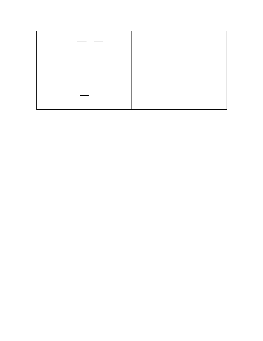
catenary and geometrical shape equations. The design will be anticlastic meaning that its
main curvatures run in opposite directions, like the hyperbolic saddle. It may be formed
out of a combination of two intersecting hyperbolic paraboloids, forming a hyperbolic
groined vault (Figure 1) or a similar complex shape. The hyperbolic paraboloid (Figure
3
2) could be formed as a curved surface or from straight boards, and is the only warped
surface whose stresses can be calculated using elementary mathematics (Faber 1963).
The analysis becomes more complicated when multiple shapes are combined and the
resulting equations will need to be derived or computed via numerical analysis. The
resulting shape will be modeled by ANSYS software. A variety of forms and dimensions
will be modeled until both aesthetics and strength of shape are maximized. AutoCAD
software will be used to produce engineering drawings of the final design.
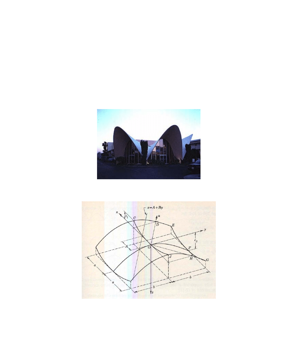
Figure 1: La Concha Motel Lobby Las Vegas (Save La Concha)
Figure 2: Diagram of a Hyperbolic Paraboloid (Billington 1982)
4
2
2
2
1
2
1
1
2
2
2
y
x
z
h
h
w h ere
a
h
c
b
h
c
=
−
=
=
Equation One
Surface of a Hyperbolic Paraboloid
The shell will be subject to analysis of stress and deflection using ANSYS finite
element software. This software will reveal critical areas and may lead to modifications
in the design if the strength of the concrete shell is surpassed at any point. The structure
will most likely be modeled using plates. A sufficient number of plates will be chosen
such that the curvature of the shell is approximated. In “An Introduction to Shell
Structures”, Michele Melaragno presents a chapter on computer analysis of shells and
domes. For a 360 degree circular domes structure she breaks the shell into 36 radial lines
each with 11 circumferential divisions. These divisions may be used to approximate the
number of plates needed to model the hyperbolic paraboloid. Melaragno also suggests
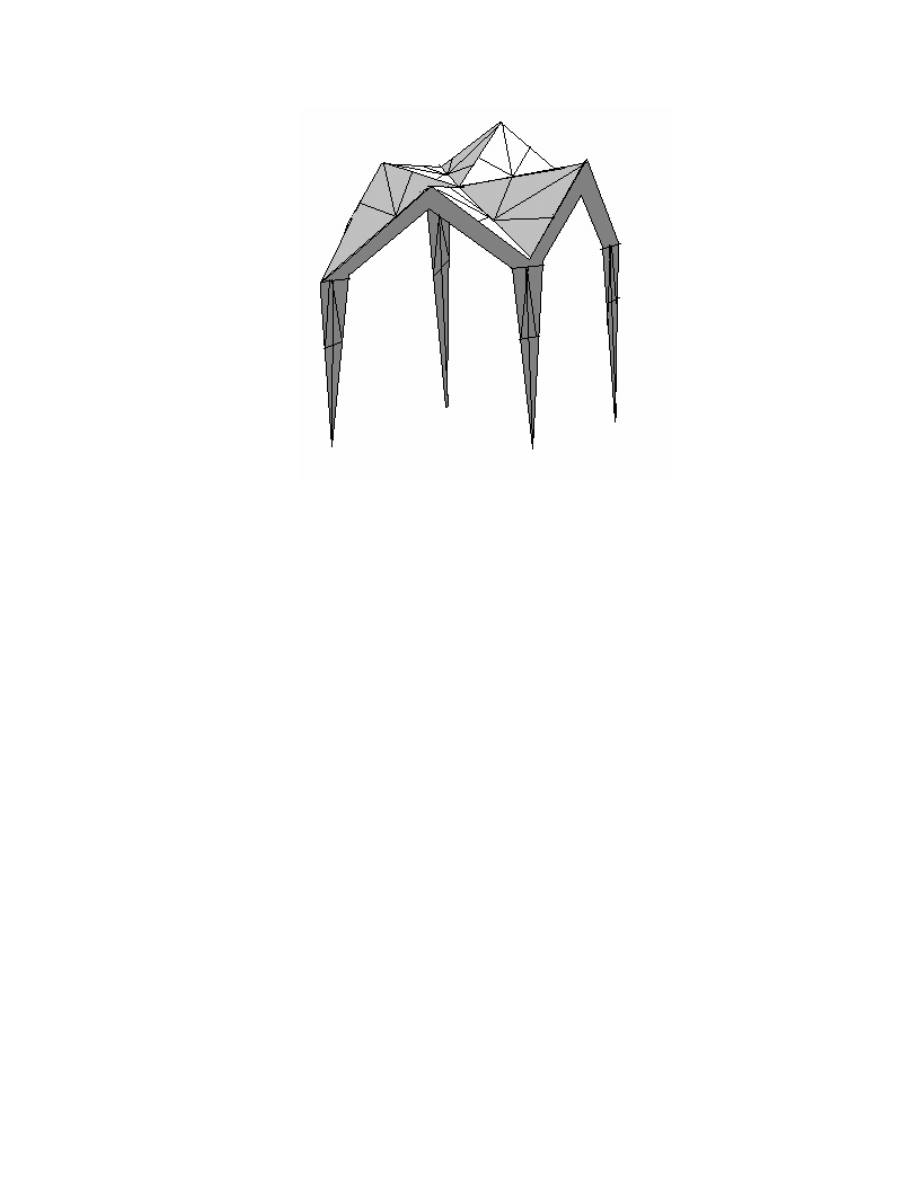
that thin shell structures could be modeled using tension and compression members in a
space frame which approximates the shape of the shell. When this space frame is
analyzed for stresses and deflections, the axial stresses indicated tension and
compression, and the stresses in diagonal members represent the shears within the
thickness of the shell. Figure 3 is a diagram indicating the application of this method to a
hyperbolic paraboloid.
5
Figure 3: Hyperbolic Paraboloid modeled as a space frame.
2.2 Materials Testing and Selection
There are two directions in which the materials for this project could be chosen.
The first direction derives from the fact that these structures use very little material. They
are therefore well suited for third world countries where resources are limited but manual
labor is abundant. The formwork used for these structures is often reusable and could be
used to make several structures of the same form. In the case that this technology was
developed for third world locations, low technology materials would be used. This would
include utilizing cheaply obtained steel reinforcement and a standard cement mortar mix
without additives.
The second direction for materials selection would be to explore new technology
products. This would include the use of additives in the concrete to increase its strength
and therefore reduce its thickness and stresses. Lightweight concrete may also be used
reducing the weight of the structure. Swarthmore alumnus John Roberts, class of 1939,
owns Solite Corporation which specializes in lightweight concrete expanded shale
aggregate. He may be consulted for information regarding the use of this material and
possibly for a donation of supplies. This material is a coarse aggregate and so could only
be utilized if the material is available in particle diameters small enough to fit within the

6
thickness and reinforcement of the shell. Solite expanded shale material was donated for
use on the green roof of Swarthmore College’s Alice Paul dormitory, so a small sample
may be obtained from this location for testing. I will also contact Swarthmore College
Facilities to see if there is any additional material remaining from this project.
Carbon fiber reinforcement products could be used instead of traditional steel
reinforcement. These materials are much lighter in weight that steel but are capable of
withstanding the tensile stresses in concrete. They are also corrosion resistant, another
improvement over steel reinforcement. These products are still relatively new within the
engineering field and have not gained widespread acceptance. Research would have to be
conducted on the performance of these materials before their usage in the structure. This
research would include tension testing and bonding strength with concrete. Tension
testing would utilize the green machine to stretch the carbon fiber until significant
yielding or failure occurred. Tensile tests would also be used to measure tensile strength
in Fiber Reinforced Polymer (FRP) bars if appropriate literature or factory values cannot
be obtained. I have not yet determined an appropriate test to measure bond strength for
carbon fabric. Cost and availability of these materials will also be taken into account
when deciding if their use is feasible.
2.3 Development of Formwork
Formwork developed for this project needs to mimic the curved surface of the
concrete shell in order to serve as the appropriate form for it. In construction practice,
there are several materials used for formwork. Wood, one of the earlier materials used,
can be bent into curved surface when in thin sheets. These thin sheets are attached to a
stronger wood framework underneath constructed of a material such as 2x4’s. Inflatable
pneumatic formwork has been used for circular concrete shell structures. A concrete base
is cast, and the pneumatic membrane is attached to the top. It is covered with concrete
and a second membrane is placed on top. The bottom membrane is allowed to inflate with
air sealing a thin shell of concrete between the two membranes. In the late 1960’s the
Dow company looking for a new market for their “Styrofoam” product developed a
process known as spiral generation to create formwork from thin layers of foam, the
7
formwork is adhered together by heat lamination and is layered inward to create a
spherical dome (Melaragno 1991)
For my project, these methods will need to be modified from a spherical form to a
more hyperbolic form with multidirectional curves. I plan to construct a wooden support
structure out of 2x4’s or Uni-Strut to hold a lightweight shapeable material. I have
already consulted with machine shop technician Grant Smith on materials to use as this
lightweight material. I proposed using a process similar to the Spiral Generation Method
in which thin sheets of foam would be stacked and carved at the ends to produce the
desired shape. This idea is generated in graphical form in Figure 4. Sample pieces of
foam were cut to a curved shape in the machine shop to demonstrate the feasibility of this
method.
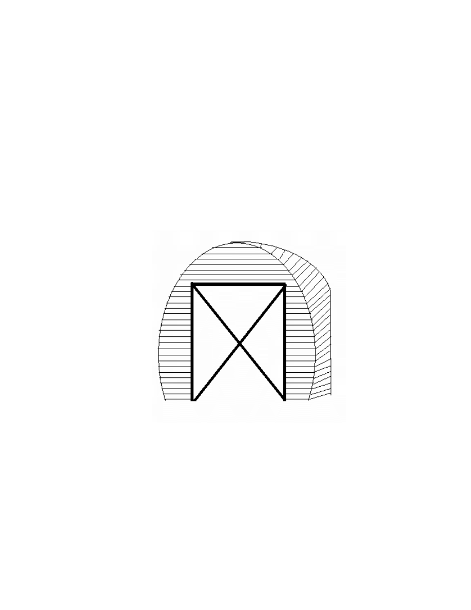
Figure 4: Foam Formwork for a Curved Section, This formwork would be used on ¼ of
a hyberbolic paraboloid, and would then be removed and reused on the remaining
portions. It is a foam curved shape supported with an inner brace of wooden 2x4’s.
2.4 Construction
Construction of the thin shell concrete structure would occur upon the completed
formwork. Reinforcement would first be prepared and spaced from the formwork so that
it will be suspended in the center of the shell structure. Fabric reinforcement would be
added for tensile strength and also as a medium for the concrete to adhere to upon the

8
formwork, holding it in place until sufficiently dried. Many assistants will be needed to
complete the task of construction. Up to 40 ft
3
of material will need to be poured and the
capacity of our mixer is only 1 ft
3
. Another mixer could be rented our borrowed which
has a larger load capacity and can run simultaneously with the department mixer. A
mixer source has not yet been identified.
3 Project
Costs
As the shape of the structure has not yet been designed, its surface area will be
approximated with that of a spherical half dome. The surface area for a dome has the
formula S.A. = 4πr
2
, considering a half sphere with a 7 foot radius to achieve the desired
height, the surface area would be 308 ft^2. For a structure one and a half inches thick,
this leaves a maximum volume of 39 ft
3
of material. (Although shells in the past
especially those designed by Felix Candela in Mexico have been less than one inch thick
ACI requirements for covering reinforcement are stricter in the United States. It is
assumed that the shell will need to be thicker than one inch, but this will not be known
until the reinforcement is designed. The code states that the shells thickness but be
sufficient to satisfy strength provisions in the code, and that the thickness of the shell is
often dictated by the required reinforcement (ACI). Additional concrete material will be
required for four bases under the legs (4 x 3”x2’x2’) = 4 ft
3
and for testing and
experimentation. Overall it is estimated that 40 ft
3
of concrete could be used. It is
assumed that no course aggregate will be used due to the thinness of structure, therefore
only fine aggregate will be required. A low slump mix will be required so that the
concrete will adhere to the formwork without sliding. An example of a low slump cement
mix contains 0.6-0.75 lb concrete to 1.0 lb of sand (Penn State). It is estimated then that
(0.75/1.75*40=17 ft^3 of cement needed) and (1/1.75*40=23 ft^3 of sand needed). One
bag of cement weights 94 lbs and is 1 ft
3
in volume.

9
Formwork:
Foam or Wooden Slats – estimated up to $100 dollars
2x4 boards – used boards will be sufficient, obtained from shop
Adhesive - $20
Shell:
Cement – 17 ft^3 = 17 bags = $15*17 = $255
Fine Aggregate – 23 ft^3 * ($20/ yd^3) = $20
Carbon Fiber or Steel Wire Mesh, will need at least 300 ft^2 of material, price is highly
dependent upon product chosen.
Other Costs:
Printing Plots: $50
Transportation: $20
Mixer Rental: ?
Total Cost: ≈$500
Suppliers will be contacted to try to arrange a donation of materials to alleviate the cost.
4
Realistic Design Constraints and Sustainability
This project involves the use of concrete as a construction material. Concrete is a
material proven to be very hard, durable, and weather resistant. It will need little
maintenance over the course of its life. This is great in terms of upkeep while the project
is located on site. However, these properties remain once the material is disposed. The
concrete is not recyclable and will end up in a landfill at the end of its useful life. This is
an unfortunate side effect of such a trusty building material. Another disadvantage to
concrete construction is the amount of energy required to produce concrete. Concrete is
formed by burning rock in a rotating kiln at extreme temperatures. Fueling this kiln

10
involves tremendous amounts of energy which has an effect on both the Earth’s resources
and pollution to the environment. Despite these negative side effects, concrete is used in
large quantities in construction projects throughout the world. The abundance of the rock
materials it is composed of make it relatively cheap and much construction is conducted
without any reference to the impact the production of the concrete had on the
environment. This project will show small contractors that it is possible to reduce
concrete consumption by more appropriately designing structures where it is efficiently
used. Our thin shell concrete structure will use a minimum of material for an extended
span. If a college student can perform this operation, so can a contractor.
This project will also serve an aesthetic purpose in its chosen location. A proposal
is being submitted to the Swarthmore College Arboretum in the hopes that the project can
be located on the Swarthmore College Campus. It will be available for the public to see
and appreciate. It may house a seasonally rotating sculptural object, a permanent
sculpture, or a plant bed. Hopefully it will also increase interest in engineering, among
those who see it.
11
5
Critical Path and Gantt Chart
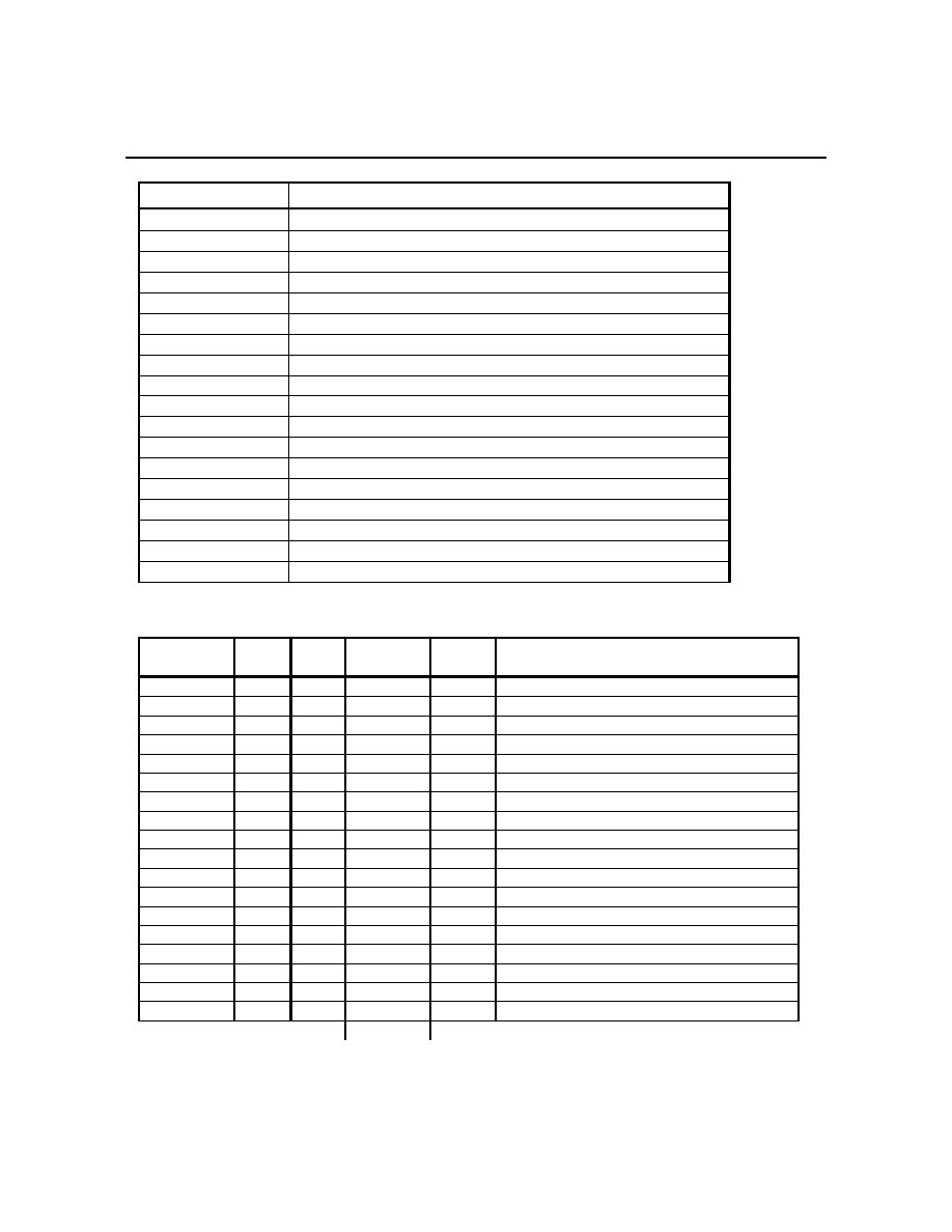
ACTIVITY ACTION
A PROPOSAL
DRAFT
B PROPOSAL
C LEARN
ANSYS
D
LITERATURE REVIEW and ARBORETUM PROPOSAL
E LEARN
AUTOCAD
F
STRUCTURAL DESIGN AND ANALYSIS
G CONCRETE
MIX
DESIGN
H MATERIALS
PURCHASE
I
TESTING OF MATERIAL PROPERTIES
J AUTOCAD
DRAWINGS
K FORMWORK
DESIGN
L
CONSTRUCTION OF FORMWORK
M CONSTRUCTION
OF
REINFORCEMENT
N
CONSTRUCTION OF SHELL
O CURING
OF
SHELL
P
INSPECTION AND ANALYSIS
Q REPORT
R PRESENTATION
Figure 4: Activities Listing
ACTIVITY NEEDS
FEEDS
DURATION
(weeks)
EFFORT
(hours)
ACTION
A x
B 1 12
PROPOSAL
DRAFT
B A
x 1 12
PROPOSAL
C x
F 3 20
LEARN
ANSYS
D
x
F
3
20
LITERATURE REVIEW and ARB. Prop.
E x
J 1 20
LEARN
AUTOCAD
F
C, D
J, H
4
60
STRUCTURAL DESIGN AND ANALYSIS
G H
I 2 30
CONCRETE
MIX
DESIGN
H F
G 1 5
MATERIALS
PURCHASE
I
G
M
1
15
TESTING OF MATERIAL PROPERTIES
J E,
F
K 3 40
AUTOCAD
DRAWINGS
K
J
L
1
35
FORMWORK DESIGN and PURCHASE
L
K
M
2
25
CONSTRUCTION OF FORMWORK
M
L, I
N
1
15
CONSTRUCTION OF REINFORCEMENT
N
M
O
1
50
CONSTRUCTION OF SHELL
O N
P 2 5
CURING
OF
SHELL
P
O
Q
1
10
INSPECTION AND ANALYSIS
Q P
x 1 10
REPORT
R P
x 1 10
PRESENTATION
TOTAL
394
Figure 5: Needs, Feeds, Duration and Effort
The project critical path and Gantt chart are located on the following pages respectively.
12
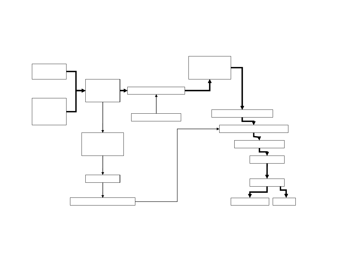
CRITICAL PATH
LEARN
ANSYS
LEARN AUTOCAD
LITERATURE
REVIEW,
ARBORETUM
PROPOSAL
STRUCTURAL
DESIGN AND
MATERIAL
SELECTION
TESTING MATERIALS / MIX
AUTOCAD DRAWINGS
FORMWORK
DESIGN and
MATERIALS
PURCHASE
CONSTRUCT FORMWORK
CONSTRUCT REINFORCEMENT
CONSTRUCT SHELL
CURE SHELL
INSPECTION
REPORT
PRESENTATION
PURCHASE
STRUCTURAL
MATERIALS
MIX DESIGN
1, 1
1, 1
5, 5
6, 6
7, 9
9, 10
7,7
9, 9
10, 10
11, 11
12, 12
13, 13
1, 5
14, 14
5,7
14, 14
CRITICAL PATH IS HIGHLIGHTED WITH BOLD ARROWS
13
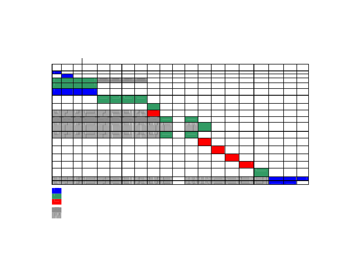
Gantt Chart for E90 Thin Shell Project
WEEK
1
2
3
4
5
6
7
8
9
10
11
12
13
14
DATES
NOV
DEC
JAN
JAN 21-28
JAN 28-
FEB 4
FEB 4-
FEB 11
FEB 11-
FEB 18
FEB 18-
FEB 25
FEB 25-
MAR 4
MAR 4-
MAR 11
BREAK MAR
18-
MAR 25
MAR 25-
APRIL 1
APRIL 1-
APRIL 8
APRIL 8-
APRIL 15
APRIL 15-
APRIL 22
APRIL 22-
APRIL 29
APRIL 29-
MAY 6
MAY 7-8
10-May
TASK
PROP DRAFT
PROPOSAL
LEARN AutoCAD
LEARN ANSYS
LITERATURE
REVIEW, ARBOR.
STRUCTURAL
DESIGN and
ANALYSIS
AUTOCAD
DRAWINGS
MATERIALS
PURCHASE
CONCRETE MIX
DESIGN
TESTING OF
MATERIAL/MIX
PROPERTIES
FORMWORK
DESIGN
CONSTRUCTION
OF FORMWORK
CONSTRUCTION
OF
REINFORCEMENT
CONSTRUCTION
OF SHELL
CURING OF
SHELL
INSPECTION AND
ANALYSIS
REPORT
PRESENTATION
text
calculation
manual
.
can be completed during this time
some aspects may be started during this time

14
8 Source
Listing
ACI. 318 Building Code and Commentary. Ch. 19 Shells and Folded Plate Members.
Billington, David. P. Thin Shell Concrete Structures, 2nd Edition. McGraw-Hill Book
Company. USA. 1982
Faber, Colin. Candela: The Shell Builder. The Architectural Press. London. 1963.
Melaragno, Michele. An Introduction to Shell Structures: The Art and Science of
Vaulting. Van Nostrand Reinhold. New York. 1991.
Penn State. Architectural Engineering Computer Lab Website.
Paul Bowers
and
John
Pillar
. 2001.
<
http://www.arche.psu.edu/thinshells/module%20III/concrete_material.htm
>.
Save La Concha. HOMECAMP.com. Lotta Livin’.
<
http://www.mondo-vegas.com/savelaconcha/architecture.php
>.
Wyszukiwarka
Podobne podstrony:
SKŁADNIA JM
O Patriotyzmie JM Bochenski htm
MR MB 05 ladowarki JM
MR 7 inne maszyny JM
Amendend proposal com 93 225
A propos tekstu dra Jaśkowskiego list prof. Majewskiej, Zdrowie i ekologia, Szczepionki
egzamin z sorbentów opracowanie pytań 1 2 JM
MO JM 02 JS 03
proposals
chem bud wyklad I JM
Propos de littérature
MR 3 Urabianie mobilnosc JM
MR 5 ladowarki JM
23 24 JM by AZ
hot proposal
Six Explanatory Propositions
MR MB 02 plac budowy grunty JM
więcej podobnych podstron