
EUROPEAN PRESTANDARD
PRENORME EUROPEENNE
EUROPÄISCHE VORNORM
Draft prEN1994-1-2
ICS …
Descriptors :
buildings, steel construction, concrete structures, design, safety requirements, accident prevention, fire protection, fire
resistance, mechanical properties, thermodynamic properties, computation, mechanical strength.
English version
Eurocode 4 – Design of composite steel and concrete structures
Part 1-2 : General rules - Structural fire design.
FINAL DRAFT (Stage 34)
2003
“Material Properties of EN 1992-1-2 and EN 1993-1-2 excluded”
Eurocode 4 – Calcul des structures mixtes acier-
béton – Partie 1-2: Règles générales – Calcul
du comportement au feu.
Eurocode 4 – Bemessung und Konstruktion von
Verbundtragwerken aus Stahl und Beton – Teil 1-2:
Allgemeine Regeln – Tragwerksbemessung für den
Brandfall.
CEN
European Committee for Standardization
Comité Européen de Normalisation
Europäisches Komitee für Normung
Central Secretariat: rue de Stassart 36, B-1050 Brussels
© 2003
Copyright reserved to all CEN members
Ref. No. prEN 1994-1-2: xxx
CEN/TC250/SC4/
N 282s
Modified – 7
th
of May 2003

Page 2
Draft prEN1994-1-2:2003
Contents
Page
...................................................................................................5
Background of the Eurocode programme..................................................................................................5
Status and field of application of Eurocodes .............................................................................................6
National Standards implementing Eurocodes ...........................................................................................6
Links between Eurocodes and harmonised technical specifications (ENs and ETAs) for products.........7
Additional information specific for EN 1994-1-2 ........................................................................................7
National Annex for EN 1994-1-2..............................................................................................................10
.................................................................................................11
1.5.1 Special terms relating to design in general…………………… ...........……………………..15
1.5.2 Terms relating to material and products properties...........................................................15
1.5.3 Terms relating to heat transfer analysis ............................................................................15
1.5.4 Terms relating to mechanical behaviour analysis .............................................................15
2.1.1 Basic requirements ............................................................................................................26
2.1.2 Nominal fire exposure........................................................................................................26
2.1.3 Parametric fire exposure....................................................................................................27
2.4.1 General ..............................................................................................................................28
2.4.2 Member analysis................................................................................................................29
2.4.3 Analysis of part of the structure .........................................................................................30
2.4.4 Global structural analysis...................................................................................................30
3.2.1 Strength and deformation properties of structural steel ....................................................31
3.2.2 Strength and deformation properties of concrete ..............................................................31
3.2.3 Reinforcing steels ..............................................................................................................32
3.3.1 Normal weight concrete .....................................................................................................32
3.3.2 Light weight concrete.........................................................................................................34
3.3.3 Fire protection materials ....................................................................................................35

Page 3
Draft prEN1994-1-2:2003
4.2.1 Scope of application ..........................................................................................................37
4.2.2 Composite beam comprising steel beam with partial concrete encasement ....................38
4.2.3 Composite columns ...........................................................................................................40
4.3.1 General rules for composite slabs and composite beams ................................................44
4.3.2 Unprotected composite slabs ............................................................................................44
4.3.3 Protected composite slabs.................................................................................................45
4.3.4 Composite beams..............................................................................................................46
4.3.5 Composite columns ...........................................................................................................54
4.4.1 Basis of analysis ................................................................................................................58
4.4.2 Thermal response..............................................................................................................58
4.4.3 Mechanical response.........................................................................................................59
4.4.4 Validation of advanced calculation models........................................................................59
5.4.1 General ..............................................................................................................................62
5.4.2 Connections between composite beams and composite columns with steel sections
5.4.3 Connections between composite beams and composite columns with partially encased
5.4.4 Connections between composite beams and composite columns with concrete filled
Annex A (INFORMATIVE) Concrete stress-strain relationships adapted to natural fires
with a decreasing heating branch for use in advanced
calculation models
65
Annex B (INFORMATIVE) Model for the calculation of the fire resistance of unprotected
composite slabs exposed to fire beneath the slab according
to the standard temperature-time curve
67
B.1
Fire resistance according to thermal insulation
67
B.2
Calculation of the sagging moment resistance M
fi,Rd
+
68
B.3
Calculation of the hogging moment resistance M
fi,Rd
-
70
B.4
Effective thickness of a composite slab
72

Page 4
Draft prEN1994-1-2:2003
Annex C (INFORMATIVE) Model for the calculation of the sagging and hogging moment
resistances of a steel beam connected to a concrete slab and
exposed to fire beneath the concrete slab.
74
C.1
Calculation of the sagging moment resistance M
fi,Rd
+
74
C.2
Calculation of the hogging moment resistance M
fi,Rd
-
at an intermediate support
(or at a restraining support)
75
C.3
Local resistance at supports
76
C.4
Vertical shear resistance
77
Annex D (INFORMATIVE) Model for the calculation of the sagging and hogging moment
resistances of a partially encased steel beam connected to a
concrete slab and exposed to fire beneath the concrete slab
according to the standard temperature-time curve .
78
D.1
Reduced cross-section for sagging moment resistance M
fi,Rd
+
78
D.2
Reduced cross-section for hogging moment resistance M
fi,Rd
-
82
Annex E (INFORMATIVE) Balanced summation model for the calculation of the fire
resistance of composite columns with partially encased
steel sections, for bending around the weak axis, exposed
to fire all around the column according to the standard
temperature-time curve.
84
E.1
Introduction
84
E.2
Flanges of the steel profile
85
E.3
Web of the steel profile
85
E.4 Concrete
86
E.5
Reinforcing bars
87
E.6
Calculation of the axial buckling load at elevated temperatures
88
E.7
Eccentricity of loading
89
Annex F (INFORMATIVE) Simple calculation model for concrete filled hollow sections
exposed to fire all around the column according to the
standard temperature-time curve.
92
F.1
Introduction
92
F.2 Temperature
distribution
92
F.3
Design axial buckling load at elevated temperature
92
F.4
Eccentricity of loading
93
Annex G (INFORMATIVE) Planning and evaluation of experimental models
97
G.1
Introduction
97
G.2
Test for global assessment
97
G.3
Test for partial information
97

Page 5
Draft prEN1994-1-2:2003
Foreword
This European Standard EN 1994-1-2, Structural Rules – Structural Fire Design has been prepared on
behalf of Technical Committee CEN/TC250/SC4 «Eurocode 4», the Secretariat of which is held by
National Standards Authority of Ireland (NSAI). CEN/TC250/SC4 is responsible for Eurocode 4.
The text of the draft standard was submitted to the formal vote and was approved by CEN as
EN 1994-1-2 on YYYY-MM-DD.
This European Standard supersedes ENV 1994-1-2:1994.
Background of the Eurocode programme
In 1975, the Commission of the European Community decided on an action programme in the field of
construction, based on article 95 of the Treaty. The objective of the programme was the elimination of
technical obstacles to trade and the harmonisation of technical specifications.
Within this action programme, the Commission took the initiative to establish a set of harmonised
technical rules for the design of construction works which, in a first stage, would serve as an alternative to
the national rules in force in the Member States and, ultimately, would replace them.
For fifteen years, the Commission, with the help of a Steering Committee with Representatives of
Member States, conducted the development of the Eurocodes programme, which led to the first
generation of European codes in the 1980’s.
In 1989, the Commission and the Member States of the EU and EFTA decided, on the basis of an
agreement
between the Commission and CEN, to transfer the preparation and the publication of the
Eurocodes to the CEN through a series of Mandates, in order to provide them with a future status of
European Standard (EN). This links de facto the Eurocodes with the provisions of all the Council’s
Directives and/or Commission’s Decisions dealing with European standards (e.g. the Council Directive
89/106/EEC on construction products – CPD - and Council Directives 93/37/EEC, 92/50/EEC and
89/440/EEC on public works and services and equivalent EFTA Directives initiated in pursuit of setting up
the internal market).
The Structural Eurocode programme comprises the following standards generally consisting of a number
of Parts:
EN 1990, Eurocode : Basis of structural design
EN 1991, Eurocode 1: Actions on structures
EN 1992, Eurocode 2: Design of concrete structures
EN 1993, Eurocode 3: Design of steel structures
EN 1994, Eurocode 4: Design of composite steel and concrete structures
EN 1995, Eurocode 5: Design of timber structures
EN 1996, Eurocode 6: Design of masonry structures
EN 1997, Eurocode 7: Geotechnical design
1
Agreement between the Commission of the European Communities and the European Committee for Standardisation (CEN)
concerning the work on EUROCODES for the design of building and civil engineering works (BC/CEN/03/89).

Page 6
Draft prEN1994-1-2:2003
EN 1998, Eurocode 8: Design of structures for earthquake resistance
EN 1999, Eurocode 9: Design of aluminium structures
Eurocode standards recognise the responsibility of regulatory authorities in each Member State and have
safeguarded their right to determine values related to regulatory safety matters at national level where
these continue to vary from State to State.
Status and field of application of Eurocodes
The Member States of the EU and EFTA recognise that EUROCODES serve as reference documents for
the following purposes :
– as a means to prove compliance of building and civil engineering works with the essential
requirements of Council Directive 89/106/EEC, particularly Essential Requirement N°1 – Mechanical
resistance and stability – and Essential Requirement N°2 – Safety in case of fire;
– as a basis for specifying contracts for construction works and related engineering services ;
– as a framework for drawing up harmonised technical specifications for construction products (ENs and
ETAs).
The Eurocodes, as far as they concern the construction works themselves, have a direct relationship with
the Interpretative Documents
referred to in Article 12 of the CPD, although they are of a different nature
from harmonised product standards
. Therefore, technical aspects arising from the Eurocodes work need
to be adequately considered by CEN Technical Committees and/or EOTA Working Groups working on
product standards with a view to achieving full compatibility of these technical specifications with the
Eurocodes.
The Eurocode standards provide common structural design rules for everyday use for the design of
whole structures and component products of both a traditional and an innovative nature. Unusual forms of
construction or design conditions are not specifically covered and additional expert consideration will be
required by the designer in such cases.
National Standards implementing Eurocodes
The National Standards implementing Eurocodes will comprise the full text of the Eurocode (including any
annexes), as published by CEN, which may be preceded by a National title page and National foreword,
and may be followed by a National annex .
The National Annex may only contain information on those parameters which are left open in the
Eurocode for national choice, known as Nationally Determined Parameters, to be used for the design of
buildings and civil engineering works to be constructed in the country concerned, i.e. :
– values and/or classes where alternatives are given in the Eurocode;
– values to be used where a symbol only is given in the Eurocode;
2
According to Art. 3.3 of the CPD, the essential requirements (ERs) shall be given concrete form in interpretative documents for the
creation of the necessary links between the essential requirements and the mandates for hENs and ETAGs/ETAs.
3
According to Art. 12 of the CPD the interpretative documents shall :
a) give concrete form to the essential requirements by harmonising the terminology and the technical bases and indicating classes
or levels for each requirement where necessary ;
b) indicate methods of correlating these classes or levels of requirement with the technical specifications, e.g. methods of
calculation and of proof, technical rules for project design, etc. ;
c) serve as a reference for the establishment of harmonised standards and guidelines for European technical approvals.
The Eurocodes, de facto, play a similar role in the field of the ER 1 and a part of ER 2.

Page 7
Draft prEN1994-1-2:2003
– country specific data (geographical, climatic, etc), e.g. snow map;
– the procedure to be used where alternative procedures are given in the Eurocode;
it may also contain:
– decisions on the application of informative annexes, and
– references to non-contradictory complementary information to assist the user to apply the Eurocode.
Links between Eurocodes and harmonised technical specifications (ENs and ETAs) for
products.
There is a need for consistency between the harmonised technical specifications for construction
products and the technical rules for works
. Furthermore, all the information accompanying the
CE Marking of the construction products which refer to Eurocodes shall clearly mention which Nationally
Determined Parameters have been taken into account.
Additional information specific for EN 1994-1-2
EN 1994-1-2 describes the Principles, requirements and rules for the structural design of buildings
exposed to fire, including the following aspects:
Safety requirements
EN 1994-1-2 is intended for clients (e.g. for the formulation of their specific requirements), designers,
contractors and public authorities.
The general objectives of fire protection are to limit risks with respect to the individual and society,
neighbouring property, and where required, environment or directly exposed property, in the case of fire.
Construction Products Directive 89/106/EEC gives the following essential requirement for the limitation of
fire risks:
"The construction works must be designed and built in such a way, that in the event of an outbreak of fire
- the load bearing resistance of the construction can be assumed for a specified period of time;
- the generation and spread of fire and smoke within the works are limited;
- the spread of fire to neighbouring construction works is limited;
- the occupants can leave the works or can be rescued by other means;
- the safety of rescue teams is taken into consideration".
According to the Interpretative Document N°2 "Safety in Case of Fire
5
" the essential requirement may be
observed by following various possibilities for fire safety strategies prevailing in the Member States like
conventional fire scenarios (nominal fires) or “natural” (parametric) fire scenarios, including passive
and/or active fire protection measures.
4
see Art.3.3 and Art.12 of the CPD, as well as clauses 4.2, 4.3.1, 4.3.2 and 5.2 of ID N°1.
5
see clauses 2.2, 3.2(4) and 4.2.3.3 of ID N°2

Page 8
Draft prEN1994-1-2:2003
The fire parts of Structural Eurocodes deal with specific aspects of passive fire protection in terms of
designing structures and parts thereof for adequate load bearing resistance and for limiting fire spread as
relevant.
Required functions and levels of performance can be specified either in terms of nominal (standard) fire
resistance rating, generally given in national regulations or, where allowed by national fire regulations,
by referring to fire safety engineering for assessing passive and active measures.
Supplementary requirements concerning, for example
- the possible installation and maintenance of sprinkler systems;
- conditions on occupancy of building or fire compartment;
- the use of approved insulation and coating materials, including their maintenance.
are not given in this document, because they are subject to specification by the competent authority.
Numerical values for partial factors and other reliability elements are given as recommended values that
provide an acceptable level of reliability. They have been selected assuming that an appropriate level of
workmanship and of quality management applies.
Design procedures
A full analytical procedure for structural fire design would take into account the behaviour of the structural
system at elevated temperatures, the potential heat exposure and the beneficial effects of active fire
protection systems, together with the uncertainties associated with these three features and the
importance of the structure (consequences of failure).
At the present time it is possible to undertake a procedure for determining adequate performance which
incorporates some, if not all, of these parameters and to demonstrate that the structure, or its
components, will give adequate performance in a real building fire. However where the procedure is
based on a nominal (standard) fire, the classification system, which calls for specific periods of fire
resistance, takes into account (though not explicitly), the features and uncertainties described above.
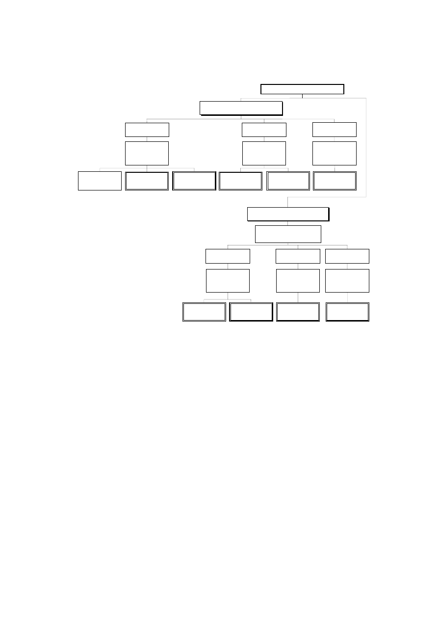
Application of this Part 1-2 is illustrated below. The prescriptive approach and the performance-based
approach are identified. The prescriptive approach uses nominal fires to generate thermal actions. The
performance-based approach, using fire safety engineering, refers to thermal actions based on physical
and chemical parameters.
For design according to this part, EN 1991-1-2 is required for the determination of thermal and
mechanical actions to the structure.
Page 9
Draft prEN1994-1-2:2003
Prescriptive Rules
(Thermal Actions given by Nominal Fire)
Tabulated
Data
Performance-Based Code
(Physically based Thermal Actions)
Selection of Simple or
Advanced Fire Development
Models
Analysis of
a Member
Determination of
Mechanical Actions
and Boundary
conditions
Selection of
Mechanical
Actions
Analysis of Part
of the Structure
Analysis of
Entire Structure
Simple Calculation
Models
Simple Calculation
Models
(if available)
Advanced
Calculation
Models
Design Procedures
Advanced
Calculation
Models
Advanced
Calculation
Models
Determination of
Mechanical Actions
and Boundary
conditions
Analysis of
a Member
Analysis of Part
of the Structure
Analysis of
Entire Structure
Determination of
Mechanical Actions
and Boundary
conditions
Determination of
Mechanical Actions
and Boundary
conditions
Selection of
Mechanical
Actions
Simple Calculation
Models
(if available)
Advanced
Calculation
Models
Advanced
Calculation
Models
Advanced
Calculation
Models
Figure — Alternative design procedures
Design aids
Apart from simple calculation models, EN 1994-1-2 gives design solutions in terms of tabulated data
(based on tests or advanced calculation models) which may be used within the specified limits of validity.
It is expected, that design aids based on the calculation models given in EN 1994-1-2, will be prepared by
interested external organizations.
The main text of EN 1994-1-2 together with informative Annexes A to G includes most of the principal
concepts and rules necessary for structural fire design of composite steel and concrete structures.

Page 10
Draft prEN1994-1-2:2003
National annex for EN 1994-1-2
This standard gives alternative procedures, values and recommendations for classes with notes
indicating where national choices may have to be made. Therefore the National Standard implementing
EN 1994-1-2 should have a National annex containing all Nationally Determined Parameters to be used
for the design of buildings and civil engineering works to be constructed in the relevant country.
National choice is allowed in EN 1994-1-2 through clauses:
– 1.1(16)
– 2.3(1)P
– 2.3(2)P
– 2.4.2(3)
– 3.3.1(6)
Page 11
Draft prEN1994-1-2:2003
Section 1
General
1.1
Scope
(1) This Part 1-2 of EN 1994 deals with the design of composite steel and concrete structures for the
accidental situation of fire exposure and is intended to be used in conjunction with EN 1994-1-1 and
EN 1991-1-2. This Part 1-2 only identifies differences from, or supplements to, normal temperature
design.
(2) This Part 1-2 of EN 1994 deals only with passive methods of fire protection. Active methods are not
covered.
(3) This Part 1-2 of EN 1994 applies to composite steel and concrete structures that are required to fulfil
certain functions when exposed to fire, in terms of:
- avoiding premature collapse of the structure (load bearing function);
- limiting fire spread (flame, hot gases, excessive heat) beyond designated areas (separating function).
(4) This Part 1-2 of EN 1994 gives principles and application rules (see EN 1991-1-2) for designing
structures for specified requirements in respect of the aforementioned functions and the levels of
performance.
(5) This Part 1-2 of EN 1994 applies to structures, or parts of structures, that are within the scope of
EN 1994-1-1 and are designed accordingly. However, no rules are given for composite elements which
include prestressed concrete parts.
(6) For all composite cross-sections longitudinal shear connection between steel and concrete should be
assured according to EN 1994-1-1 or by tests (see also 4.3.4.1(3) and Annex G).
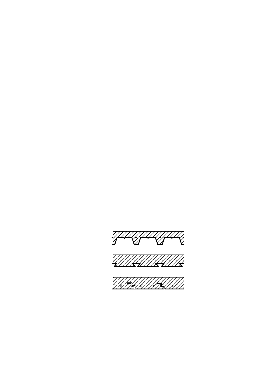
(7) Typical examples of concrete slabs with profiled steel sheets with or without reinforcing bars are given
in Figure 1.1.
Trapezoidal
profile
Re-entrant profile
Flat profile
Figure 1.1
Page 12
Draft prEN1994-1-2:2003
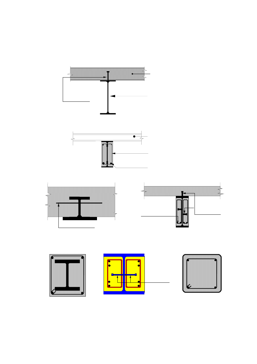
(8) Typical examples of composite beams are given in Figures 1.2 to 1.5. The corresponding
constructional detailing is covered in section 5.
Profiles with
or without
protection
Shear
connectors
Flat concrete slab or
composite slab with
profiled steel sheeting
Figure 1.2: Composite beam comprising steel beam with no concrete encasement
Optional
Stirrups welded
to web of profile
Reinforcing bar
Figure 1.3: Steel beam with partial concrete encasement
Reinforcing bar
Reinforcing
bar
Shear
connectors
Figure 1.4: Steel beam partially encased in slab
Figure 1.5: Composite beam comprising steel
beam with partial concrete encasement
(9) Typical examples of composite columns are given in Figures 1.6 to 1.8. The corresponding
constructional detailing is covered in section 5.
Shear
connectors
welded to
web of
profile
Figure 1.6:
Concrete encased profiles
Figure 1.7:
Partially encased profiles
Figure 1.8:
Concrete filled profiles

Page 13
Draft prEN1994-1-2:2003
(10) Different shapes, like circular or octagonal cross-sections may also be used for columns. Where
appropriate, reinforcing bars may be replaced by other steel sections like half sections, core sections etc.
(11) The fire resistance of these types of constructions may be increased by applying fire protection
materials.
NOTE:
The design principles and rules given in 4.2, 4.3 and 5 refer to steel surfaces directly exposed to the
fire, which are free of any fire protection material, unless explicitly specified otherwise.
(12)P The methods given in this Part 1-2 of EN 1994 are applicable to structural steel grades S235,
S275, S355, S420 and S460 of EN 10025, EN 10210-1 and EN 10219-1.
(13) For profiled steel sheeting, reference is made to section 3.5 of EN 1994-1-1.
(14) Reinforcing bars should be in accordance with EN 10080.
(15) Normal weight concrete, as defined in EN 1994-1-1, is applicable to the fire design of composite
structures. The use of light weight concrete is permitted for composite slabs which may be connected or
not to the steel beam below.
(16) This part of EN 1994 does not cover the design of composite structures with concrete strength
classes lower than C20/25 and LC20/25 and higher than C60/75 and LC60/75.
NOTE :
Information on Concrete Strength Classes > C60/75 is given in section 6 of EN 1992-1-2. The use
of these concrete strength classes may be specified in the National Annex.
(17) For materials not included herein, reference should be made to relevant CEN product standards or
European Technical Approval (ETA).
1.2
Normative references
(1)P The following normative documents contain provisions which, through reference in this text,
constitute provisions of this European Standard. For dated references, subsequent amendments to, or
revisions of, any of these publications do not apply. However, parties to agreements based on this
European Standard are encouraged to investigate the possibility of applying the most recent editions of
the normative documents indicated below. For undated references, the latest edition of the normative
document referred to applies.
EN 1365
"Test methods for fire resistance of load bearing elements"
Part 1
"Fire resistance of walls"
Part 2
"Fire resistance of floors and roofs"
Part 3
"Fire resistance of beams"
Part 4
"Fire resistance of columns"
EN 10025
"Hot rolled products of non-alloy structural steels: Technical delivery conditions"
EN 10025-1:January 2002 Hot-rolled products of structural steels
Part 1:
General technical delivery conditions.
EN 10025-2:January 2002 Hot-rolled products of structural steels
Part 2:
Technical delivery conditions for non-alloy structural steels.
EN 10025-3:January 2002 Hot-rolled products of structural steels
Part
3:
Technical delivery conditions for normalized/normalized rolled
weldable fine grain structural steels.

Page 14
Draft prEN1994-1-2:2003
EN 10025-4:March 2002
Hot-rolled products of structural steels
Part 4:
Technical delivery conditions for thermomechanical rolled weldable
fine grain structural steels.
EN 10025-5:January 2002 Hot-rolled products of structural steels
Part 5:
Technical delivery conditions for structural steels with improved
atmospheric corrosion resistance.
EN 10025-6:January 2002 Hot-rolled products of structural steels
Part 6:
Technical delivery conditions for flat products of high yield strength
structural steels in the quenched and tempered condition.
EN 10080
“Steel for the reinforcement of concrete. Weldable ribbed reinforcement steel
B 500 – Technical delivery conditions for bars, coils and welded fabric”
EN 10210-1
“Hot finished structural hollow sections of non-alloy and fine grain structural
steels: Technical delivery conditions”
EN 10219-1
“Cold formed welded structural hollow sections of non-alloy and fine grain
structural steels: Technical delivery conditions”
ENV 13381
"Method of test for the determination of the contribution to fire resistance of
structural members"
Part 1
"Membrane protection - horizontal"
Part 2
"Membrane protection - vertical"
Part 3
"Concrete elements"
Part 4
"Steel elements"
Part 5
"Flat concrete/profiled sheet composite elements"
Part 6
"Concrete filled hollow steel columns"
EN 1990
"Eurocode : Basis of structural design"
EN 1991
"Eurocode 1: Actions on Structures"
Part 1.1
"General Actions - Densities, self-weight and imposed loads"
Part 1.2
"Actions on structures exposed to fire"
Part 1.3
"Actions on structures - Snow loads"
Part 1.4
"Actions on structures - Wind loads"
EN 1992
"Eurocode 2: Design of concrete structures"
Part 1.1
"General rules and rules for buildings"
Part 1.2
"Structural fire design"
EN 1993
"Eurocode 3: Design of steel structures"
Part 1.1
"General rules and rules for buildings"
Part 1.2
"Structural fire design"
Part 1.5
“Plated structural elements”
EN 1994
"Eurocode 4: Design of composite steel and concrete structures"
Part 1.1
"General rules and rules for buildings"

Page 15
Draft prEN1994-1-2:2003
1.3 Assumptions
(1)P Assumptions of EN 1990 and EN 1991-1-2 apply.
1.4 Distinction between Principles and Application Rules
(1) The rules given in EN 1990 clause 1.4 apply.
1.5 Definitions
(1)P The rules given in clauses 1.5 of EN 1990 and EN 1991-1-2 apply
(2)P The following terms are used in Part 1-2 of EN 1994 with the following meanings:
1.5.1 Special terms relating to design in general
1.5.1.1
axis distance
distance between the axis of the reinforcing bar and the border of concrete
1.5.1.2
part of structure
isolated part of an entire structure with appropriate support and boundary conditions
1.5.1.3
protected members
members for which measures are taken to reduce the temperature rise in the member due to fire
1.5.2 Terms relating to material and products properties
1.5.2.1
failure time of protection
duration of protection against direct fire exposure; that is the time when the fire protective claddings or
other protection fall off the composite member, or other elements aligned with that composite member fail
due to collapse, or the alignment with other elements is terminated due to excessive deformation of the
composite member
1.5.2.2
fire protection material
any material or combination of materials applied to a structural member for the purpose of increasing its
fire resistance
1.5.3 Terms relating to heat transfer analysis
1.5.3.1
section factor
for a steel member, the ratio between the exposed surface area and the volume of steel; for an enclosed
member, the ratio between the internal surface area of the exposed encasement and the volume of steel

Page 16
Draft prEN1994-1-2:2003
1.5.4 Terms relating to mechanical behaviour analysis
1.5.4.1
critical temperature of structural steel
for a given load level, the temperature at which failure is expected to occur in a structural steel element
for a uniform temperature distribution
1.5.4.2
critical temperature of reinforcement
the temperature of the reinforcement at which failure in the element is expected to occur at a given load
level
1.5.4.3
effective cross section
cross section of the member in structural fire design used in the effective cross section method. It is
obtained by removing parts of the cross section with assumed zero strength and stiffness
1.5.4.4
maximum stress level
for a given temperature, the stress level at which the stress-strain relationship of steel is truncated to
provide a yield plateau
1.6
Symbols
(1)P For the purpose of this Part 1-2 of EN 1994, the following symbols apply
Latin upper case letters
A
cross-sectional area, or concrete volume of the rib per m rib length
A
a,
θ
cross-sectional area of the steel profile at the temperature
θ
A
c,
θ
cross-sectional area of the concrete at the temperature
θ
A
f
cross-sectional area of the steel section
A
i,
A
j
elemental area of the cross section with a temperature
θ
i
or
θ
j
or the exposed surface area of the part i of the steel cross-section per unit length
A/L
r
the rib geometry factor
A
i
/ V
i
section factor [m-1] of the part i of the steel cross-section (non-protected member)
A
m
directly heated surface area of member per unit length
A
m
/V
section factor of structural member
A
p,i
area of the inner surface of the fire protection material per unit length of the part i of
the steel member
A
p,i
/ V
i
section factor [m-1] of the part i of the steel cross-section (with contour protection)
A
r
cross-sectional area of the stiffeners
A
r
/V
r
section factor of stiffeners
A
s,
θ
cross-sectional area of the reinforcing bars at the temperature
θ

Page 17
Draft prEN1994-1-2:2003
E
integrity criterion
E 30
or E 60,...a member meeting the integrity criterion for 30, or 60... minutes in standard
fire exposure
E
a
characteristic value for the modulus of elasticity of structural steel at 20°C
E
a,f
characteristic value for the modulus of elasticity of a profile steel flange
a,
θ
characteristic value for the slope of the linear elastic range of the stress-strain
relationship of structural steel at elevated temperatures
E
a,
θ,σ
tangent modulus of the stress-strain relationship of the steel profile at elevated
temperature
θ and for stress σ
i,
θ
E
c,sec,
θ
characteristic value for the secant modulus of concrete in the fire situation, given by
fc,θ divided by εcu,θ
E
c0,
θ
characteristic value for the tangent modulus at the origin of the stress-strain
relationship for concrete at elevated temperatures and for short term loading
E
c,
θ
,
σ
tangent modulus of the stress-strain relationship of the concrete at elevated
temperature
θ and for stress σ
i,
θ
E
d
design effect of actions for normal temperature design
EF
external fire exposure curve
E
fi,d
design effect of actions in the fire situation, supposed to be time independent
E
fi,d,t
design effect of actions, including indirect fire actions and loads in the fire situation,
at time t
(EI)
fi,c,z
flexural stiffness in the fire situation (related to the central axis Z of the composite
cross-section)
(EI)
fi,eff
effective flexural stiffness
(EI)
fi,f,z
flexural stiffness of the two flanges of the steel profile in the fire situation (related to
the central axis Z of the composite cross-section)
(EI)
fi,s ,z
flexural stiffness of the reinforcing bars in the fire situation (related to the central axis
Z of the composite cross-section)
(EI)
fi,eff,z
effective flexural stiffness (for bending around axis z)
(EI)
fi,w,z
flexural stiffness of the web of the steel profile in the fire situation (related to the
central axis Z of the composite cross-section)
E
k
characteristic value of the modulus of elasticity
E
s
modulus of elasticity of the reinforcing bars

Page 18
Draft prEN1994-1-2:2003
s,
θ
characteristic value for the slope of the linear elastic range of the stress-strain
relationship of reinforcing steel at elevated temperatures
E
s,
θ
,
σ
tangent modulus of the stress-strain relationship of the reinforcing steel at elevated
temperature
θ and for stress σ
i,
θ
F
a
compressive force in the steel profile
F
+
, F
-
total compressive force in the composite section in case of sagging, or hogging
bending moments
F
c
compression force in the slab
G
k
characteristic value of a permanent action
HC
hydrocarbon fire exposure curve
I
thermal insulation criterion
I
i,
θ
second moment of area, of the partially reduced part i of the cross-section for
bending around the weak or strong axis
I 30
or I 60,... a member meeting the thermal insulation criterion for 30, or 60... minutes in
standard fire exposure
L
system length
M
bending moment
M
fi,Rd
+
;
M
fi,Rd
-
design value of the sagging or hogging moment resistance in the fire situation
M
fi,t,Rd
design moment resistance in the fire situation at time t
N
number of shear connectors in one critical length,
or axial load
N
equ
equivalent axial load
N
fi,cr
elastic critical load (
≡ Euler buckling load) in the fire situation
N
fi,cr,z
elastic critical load (
≡ Euler buckling load) around the axis Z in the fire situation
N
fi,pl,Rd
design value of the plastic resistance to axial compression of the total cross-section
in the fire situation
N
fi,Rd
design value of the resistance of a member in axial compression (
≡ design axial
buckling load) and in the fire situation
N
fi,Rd,z
design value of the resistance of a member in axial compression for bending around
the axis Z
N
fi,Sd
design value of the axial load in the fire situation
N
Rd
axial buckling load at normal temperature

Page 19
Draft prEN1994-1-2:2003
N
s
normal force in the hogging reinforcement (A
s
. f
sy
)
P
Rd
design shear resistance of a headed stud automatically welded
P
fi,Rd
design shear resistance in the fire situation of a shear connector
Q
k,1
characteristic value of the leading variable action 1
R
Load bearing criterion
R 30
or R 60, R90, R120, R180, R240... a member meeting the load bearing criterion for
30, 60, 90, 120, 180 or 240 minutes in standard fire exposure
R
d
design resistance for normal temperature design
R
fi,d,t
design resistance in the fire situation, at time t
R
fi,y,Rd
design crushing resistance
T
tensile force
V
volume of the member per unit length
V
b
,
fi,Rd
design shear plastic resistance
V
fi,Rd
design shear plastic resistance of local buckling of the steel web
V
fi,Sd
shear resistance of the steel web
V
i
volume of the part i of the steel cross section per unit length [m
3
/m]
X
X (horizontal) axis
X
fi,d
design values of mechanical (strength and deformation) material properties
X
k
characteristic value of a strength or deformation property for normal temperature
design
X
k
,
θ
value of a material property in fire design, generally dependant on the material
temperature
Y
Y (vertical) axis
Z
Z (column) central axis of the composite cross-section
Latin lower case letters
a
w
throat thickness of weld (connection between steel web and stirrups)
b
width of the steel section
b
1
width of the bottom flange of the steel section
b
2
width of the upper flange of the steel section

Page 20
Draft prEN1994-1-2:2003
b
c
depth of the composite column made of a totally encased section,
or width of concrete partially encased steel beams
b
c,fi
width reduction of the encased concrete between the flanges
b
c,fi,min
minimum value of the width reduction of the encased concrete between the flanges
b
eff
effective width of the concrete slab
b
fi
width reduction of upper flange
c
specific heat,
or buckling curve,
or concrete cover from edge of concrete to border of structural steel
c
a
specific heat of steel
c
c
specific heat of normal weight concrete
c
p
is the specific heat of the fire protection material
d
diameter of the composite column made of concrete filled hollow section, or
diameter of the studs welded to the web of the steel profile
d
p
thickness of the fire protection material
e
thickness of profile or hollow section
e
1
thickness of the bottom flange of the steel profile
e
2
thickness of the upper flange of the steel profile
e
f
thickness of the flange of the steel profile
e
w
thickness of the web of the steel profile
f
amax,
θ
characteristic value for the maximum stress level of the truncated stress-strain
relationship of structural steel in the fire situation
f
amax,
θ
cr
strength of steel at critical temperature
θ
cr
f
ap
,
θ
; f
sp,
θ
characteristic value for the proportional limit of structural or reinforcing steel at
elevated temperatures
f
au,
θ
characteristic value for the tensile strength of structural steel or steel of stud
connectors in the fire situation
f
ay
characteristic value for the yield point of structural steel at 20°C
f
c
characteristic value of the compressive cylinder strength of concrete at 28 days and
at 20°C.
f
c,j
design strength of concrete part j at 20°C.
f
c
,
θ
characteristic value for the compressive cylinder strength of concrete in the fire
situation at temperature
θ°C.

Page 21
Draft prEN1994-1-2:2003
f
c,
θ
n
residual compressive strength of concrete heated to a maximum temperature (with
n layers)
f
c,
θ
max
residual compressive strength of concrete heated to a maximum temperature
f
fi,d
design strength property in the fire situation
f
k
characteristic value of the material strength
f
ry
, f
sy
characteristic value for the yield point of a reinforcing bar at 20°C
f
smax,
θ
characteristic value for the maximum stress level of the truncated stress-strain
relationship of reinforcing steel in the fire situation
f
smax,
θ
s
characteristic value for the maximum stress level of the truncated stress-strain
relationship of longitudinal tensile reinforcing bars in the fire situation
f
y,i
nominal yield strength f
y
for the elemental area A
i
taken as positive on the
compression side of the plastic neutral axis and negative on the tension side
h
depth or height of the steel section
h
1
height of the upper concrete part situated on the re-entrant steel sheet profile or on
the trapezoidal steel profile
h
2
height of the bottom concrete part situated on the re-entrant steel sheet profile or on
the trapezoidal steel profile
h
3
thickness of the screed situated on top of the concrete
h
c
depth of the composite column made of a totally encased section,
or thickness of the concrete slab
h
eff
effective thickness of a composite slab
h
fi
height reduction of the encased concrete between the flanges
h
•
net
design value of the net heat flux per unit area
h
•
net,c
design value of the net heat flux per unit area by convection
h
•
net,r
design value of the net heat flux per unit area by radiation
h
u
thickness of the compressive zone
h
u,n
thickness of the compressive zone (with n layers)
h
v
height of the stud welded on the web of the steel profile
h
w
height of the web of the steel profile
k
c,
θ
reduction factor of compressive strength of concrete giving the strength at elevated
temperature f
c
,
θ

Page 22
Draft prEN1994-1-2:2003
k
E,
θ
reduction factor of the elastic modulus of structural steel giving the slope of the linear
elastic range at elevated temperature
a,
θ
k
max,
θ
reduction factor of the yield point of structural steel giving the maximum stress level
at elevated temperature f
amax,
θ
k
p,
θ
reduction factor of the yield point of structural steel or reinforcing bars giving the
proportional limit at elevated temperature f
ap
,
θ
k
r
, k
s
reduction factor of the yield point of a reinforcing bar
k
shadow
correction factor for the shadow effect
k
u,
θ
reduction factor of the yield point of structural steel or reinforcing bars giving the
strain hardening stress level at elevated temperature f
au
,
θ
k
θ
reduction factor for a strength or deformation property dependent on the material
temperature
l
length or buckling length
l
1
, l
2
,l
3
specific dimensions of the re-entrant steel sheet profile or the trapezoidal steel
profile
l
w
length (connection between steel profile and the encased concrete)
l
θ
buckling length of the column in the fire situation
s
s
length of the rigid support (calculation of the crushing resistance of stiffeners)
t
duration of fire exposure
t
fi,d
design value of standard fire resistance of a member
t
fi,requ
required standard fire resistance
t
i
the fire resistance with respect to thermal insulation
u
geometrical average of the axis distances u
1
and u
2
(composite section with partially
encased steel profile)
u
1
; u
2
shortest distance of the centre of the reinforcement bar to the inner steel flange or to
the concrete surface
z
i
;
z
j
distance from the plastic neutral axis to the centroid of the elemental area A
i
or
A
j
Greek letters upper case letters
∆
l
thermal elongation of steel
∆
l/l
related
thermal elongation
∆
t
time interval

Page 23
Draft prEN1994-1-2:2003
∆θ
a,t
increase of temperature of a steel beam during the time interval
∆
t
∆θ
t
increase of the ambiant gaz temperature [°C] during the time interval
∆
t
Φ
Configuration or view factor
Greek letters lower case letters
α
angle of the web
α
c
convective heat transfer coefficient
α
slab
coefficient taking into account the assumption of the rectangular stress block when
designing slabs
χ
reduction or correction coefficient and factor
χ
z
reduction or correction coefficient and factor (for bending around axis z)
δ
eccentricity
ε
strain
ε
a
axial strain of the steel profile of the column
ε
a,
θ
strain
ε
ae,
θ
ultimate strain
ε
amax,
θ
yield strain
ε
ap,
θ
strain at the proportional limit
ε
au,
θ
limiting strain for yield strength
ε
c
axial strain of the concrete of the column
ε
c,
θ
concrete strain in the fire situation
ε
ce,
θ
maximum concrete strain in the fire situation
ε
ce,
θ
max
maximum concrete strain in the fire situation at the maximum temperature
ε
cu,
θ
concrete strain corresponding to
f
c,
θ
ε
cu,
θ
max
concrete strain at the maximum concrete temperature
ε
f
emissivity coefficient of the fire
ε
m
emissivity coefficient related to the surface material of the member
ε
s
axial deformation of the reinforcing steel of the column

Page 24
Draft prEN1994-1-2:2003
φ
b
diameter of a bar
φ
s
diameter of a stirrup
φ
r
diameter of a longitudinal reinforcement (corner of the stirrups)
γ
G
partial safety factor for permanent action G
k
γ
M,fi
partial material safety factor in fire design
γ
M,fi,a
partial safety factor of the steel profile in fire design
γ
M,fi,c
partial safety factor of the concrete in fire design
γ
M,fi,s
partial safety factor of the reinforcing bars in fire design
γ
M,fi,v
partial safety factor of the stud connectors in fire design
γ
Q
partial safety factor for variable action Q
k
γ
v
partial safety factor of the stud connectors for design at normal temperature
η
load level according to EN 1994-1-1
η
fi
reduction factor applied to E
d
in order to obtain E
fi,d
η
fi,t
load level for fire design
ϕ
a,
θ
reduction coefficient for the steel profile depending on the effect of thermal stresses
ϕ
c,
θ
reduction coefficient for the concrete depending on the effect of thermal stresses
ϕ
s,
θ
reduction coefficient for reinforcing bars depending on the effect of thermal stresses
λ
a
thermal conductivity of steel
λ
c
thermal conductivity of concrete
λ
p
thermal conductivity of the fire protection material
λ
relative slenderness
λ
θ
relative slenderness of stiffeners
θ
temperature
θ
a
temperature of structural steel
θ
a,t
steel temperature at time t supposed to be uniform in each part of the steel cross-
section

Page 25
Draft prEN1994-1-2:2003
θ
c
temperature
of
concrete
θ
cr
critical temperature of structural member
θ
i
temperature in the elemental area A
i
θ
lim
limiting temperature
θ
max
maximum temperature
θ
r
the temperature of stiffner
θ
R
the temperature of additional reinforcement in the rib
θ
s
temperature of reinforcing steel
θ
t
ambiant gas temperature at time t
θ
v
temperature of stud connectors
θ
w
temperature in the web
ρ
a
density of steel
ρ
c
density of concrete
ρ
c,NC
density of normal weight concrete
ρ
c,LC
density of light weight concrete
ρ
p
density of the fire protection material
σ
stress
σ
a,
θ
stress of the steel profile in the fire situation
σ
c,
θ
stress of concrete under compression in the fire situation
σ
s,
θ
stress of reinforcing steel in the fire situation
ξ
reduction factor for unfavourable permanent action G
k
ψ
0,1
combination factor for the characteristic value of a variable action
ψ
1,1
combination factor for the frequent value of a variable action
ψ
2,1
combination factor for the quasi-permanent value of a variable action
ψ
fi
combination factor for a variable action in the fire situation, given either by
ψ
1,1
or
ψ
2,1

Page 26
Draft prEN1994-1-2:2003
Section 2
Basis of design
2.1 Requirements
2.1.1
Basic requirements
(1)P Where mechanical resistance in the case of fire is required, composite steel and concrete structures
shall be designed and constructed in such a way that they maintain their load bearing function during the
relevant fire exposure.
(2)P Where compartmentation is required, the elements forming the boundaries of the fire compartment,
including joints, shall be designed and constructed in such a way that they maintain their separating
function during the relevant fire exposure. This shall ensure, where relevant, that:
- integrity failure does not occur;
- insulation failure does not occur.
NOTE 1: See for definition EN 1991-1-2, chapters 1.5.1.8 and 1.5.1.9
NOTE 2: In case of a composite slab, the thermal radiation criterion is not relevant.
(3)P Deformation criterion shall be applied where the means of protection, or the design criterion for
separating members, require consideration of the deformation of the load bearing structure.
(4) Consideration of the deformation of the load bearing structure is not necessary in the following cases,
as relevant:
- the efficiency of the means of protection has been evaluated according to 3.3.3 and
- the separating elements have to fulfill requirements according to a nominal fire exposure.
2.1.2
Nominal fire exposure
(1)P For the standard fire exposure, members shall comply with criteria R, E and I as follows:
- separating only: integrity (criterion E) and, when requested, insulation (criterion I);
- load bearing only: mechanical resistance (criterion R);
- separating and load bearing: criteria R, E and, when requested, I.
(2) Criterion “R” is assumed to be satisfied where the load bearing function is maintained during the
required time of fire exposure.
(3) Criterion “I” may be assumed to be satisfied where the average temperature rise over the whole of
the non-exposed surface is limited to 140 °K, and the maximum temperature rise at any point of that
surface does not exceed 180 °K.
(4) With the external fire exposure curve the same criteria should apply, however the reference to this
specific curve should be identified by the letters "EF".
NOTE : See EN 1991-1-2, chapters 1.5.3.5 and 3.2.2

Page 27
Draft prEN1994-1-2:2003
(5) With the hydrocarbon fire exposure curve the same criteria should apply, however the reference to
this specific curve should be identified by the letters "HC".
NOTE : See EN 1991-1-2, chapters 1.5.3.11 and 3.2.3
2.1.3
Parametric fire exposure
(1) The load-bearing function is ensured when collapse is prevented during the complete duration of the
fire including the decay phase or during a required period of time.
(2) The separating function with respect to insulation is ensured when
- at the time of the maximum gas temperature, the average temperature rise over the whole of the non-
exposed surface is limited to 140 K, and the maximum temperature rise at any point of that surface
does not exceed 180 K,
- during the decay phase of the fire or up to a required period of time, the average temperature rise over
the whole of the non-exposed surface is limited to 200 K, and the maximum temperature rise at any
point of that surface does not exceed 240 K .
2.2
Actions
(1)P The thermal and mechanical actions shall be taken from EN 1991-1-2.
(2) In addition to 3.1(6) of EN 1991-1-2, the emissivity coefficient related to the surface material of the
member should be for steel and concrete,
m
ε
= 0,7.
2.3
Design values of material properties
(1)P Design values of mechanical (strength and deformation) material properties X
fi,d
are defined as
follows:
fi
,
M
k
d
,
fi
X
k
X
γ
θ
=
(2.1)
where:
k
X
is the characteristic value of a strength or deformation property (generally f
k
or E
k
) for normal
temperature design according to EN 1994-1-1;
θ
k
is the reduction factor for a strength or deformation property
(
)
k
,
k
X
X
θ
, dependent on the
material temperature, see 3.2;
fi
,
M
γ
is the partial safety factor for the relevant material property, for the fire situation.
NOTE 1: For mechanical properties of steel and concrete, the recommended values of the partial safety
factor for the fire situation are
γ
M,fi,a
= 1,0;
γ
M,fi,s
= 1,0;
γ
M,fi,c
= 1,0;
γ
M,fi,v
= 1,0; where modifications
are required, these may be defined in the relevant National Annexes of EN 1992-1-2 and
EN 1993-1-2.
NOTE 2: If the given numerical values are modified, tables with tabulated data may need adaptation.

Page 28
Draft prEN1994-1-2:2003
(2)P Design values of thermal material properties
d
,
fi
X
are defined as follows:
- if an increase of the property is favourable for safety;
fi
,
M
,
k
d
,
fi
X
X
γ
θ
=
(2.2a)
- if an increase of the property is unfavourable for safety.
θ
γ
,
k
fi
,
M
d
,
fi
X
X
=
(2.2b)
where:
θ
,
k
X
is the value of a material property in fire design, generally dependent on the material
temperature, see 3.3;
fi
,
M
γ
is the partial safety factor for the relevant material property, for the fire situation.
NOTE 1: For thermal properties of steel and concrete, the recommended value of the partial safety factor for
the fire situation is
γ
M,fi
= 1,0; where modifications are required, these may be defined in the
relevant National Annexes of EN 1992-1-2 and EN 1993-1-2.
NOTE 2: If the given numerical values are modified, tables with tabulated data may need adaptation.
(3) The design value of the compressive concrete strength should be taken as 1,0 f
c
divided by
c
,
fi
,
M
γ
,
before applying the required strength reduction due to temperature and given in 3.2.2.
2.4
Verification methods
2.4.1
General
(1)P The model of the structural system adopted for design to this Part 1-2 of EN 1994 shall reflect the
expected performance of the structure in fire.
(2)P It shall be verified for the relevant duration of fire exposure t :
t,
d
,
fi
t,
d
,
fi
R
E
≤
(2.3)
where:
t,
d
,
fi
E
is the design effect of actions for the fire situation, determined in accordance with EN 1991-1-2,
including the effects of thermal expansions and deformations;
t,
d
,
fi
R
is the corresponding design resistance in the fire situation.
(3) The structural analysis for the fire situation should be carried out according to 5.1.4(2) of EN 1990.
NOTE:
For verifying standard fire resistance requirement, a member analysis is sufficient.
(4) Where application rules given in this Part 1-2 are valid only for the standard temperature-time curve,
this is identified in the relevant clauses.
(5) Tabulated data given in 4.2 are based on the standard temperature-time curve.
(6)P As an alternative to design by calculation, fire design may be based on the results of fire tests, or on
fire tests in combination with calculations, see EN 1990 clause 5.2.

Page 29
Draft prEN1994-1-2:2003
2.4.2
Member analysis
(1) The effect of actions should be determined for time t = 0 using combination factors
ψ
1
,
1
or
ψ
1
,
2
according to 4.3.1(2) of EN 1991-1-2.
(2) As a simplification to (1), the effect of actions
t,
d
,
fi
E
may be obtained from a structural analysis for
normal temperature design as :
d
fi
d
,
fi
t,
d
,
fi
E
E
E
η
=
=
(2.4)
where:
d
E
is the design value of the corresponding force or moment for normal temperature design, for a
fundamental combination of actions (see EN 1990)
fi
η
is the reduction factor of
d
E
(3) The reduction factor
fi
η
for load combination (6.10) in EN 1990 should be taken as:
fi
η =
Q
+
G
Q
+
G
k,1
Q,1
k
G
k,1
fi
k
γ
γ
ψ
(2.5)
or for load combinations (6.10a) and (6.10b) in EN 1990 as the smaller value given by the two following
expressions:
fi
η
=
Q
+
G
Q
+
G
k,1
1
,
0
Q,1
k
G
k,1
fi
k
ψ
γ
γ
ψ
(2.5a)
fi
η
=
Q
+
G
Q
+
G
k,1
Q,1
k
G
k,1
fi
k
γ
ξγ
ψ
(2.5b)
where:
Q
k,1
is the characteristic value of the leading variable action 1
G
k
is the characteristic value of a permanent action
γ
G
is the partial factor for permanent actions
γ
1
,
Q
is the partial factor for variable action 1
ξ
is a reduction factor for unfavourable permanent action
G
k
ψ
1
,
0
combination factor for the characteristic value of a variable action
ψ
fi
is the combination factor for fire situation, given either by
ψ
1
,
1
(frequent value) or
ψ
1
,
2
(quasi-
permanent value) according to 4.3.1(2) of EN 1991-1-2
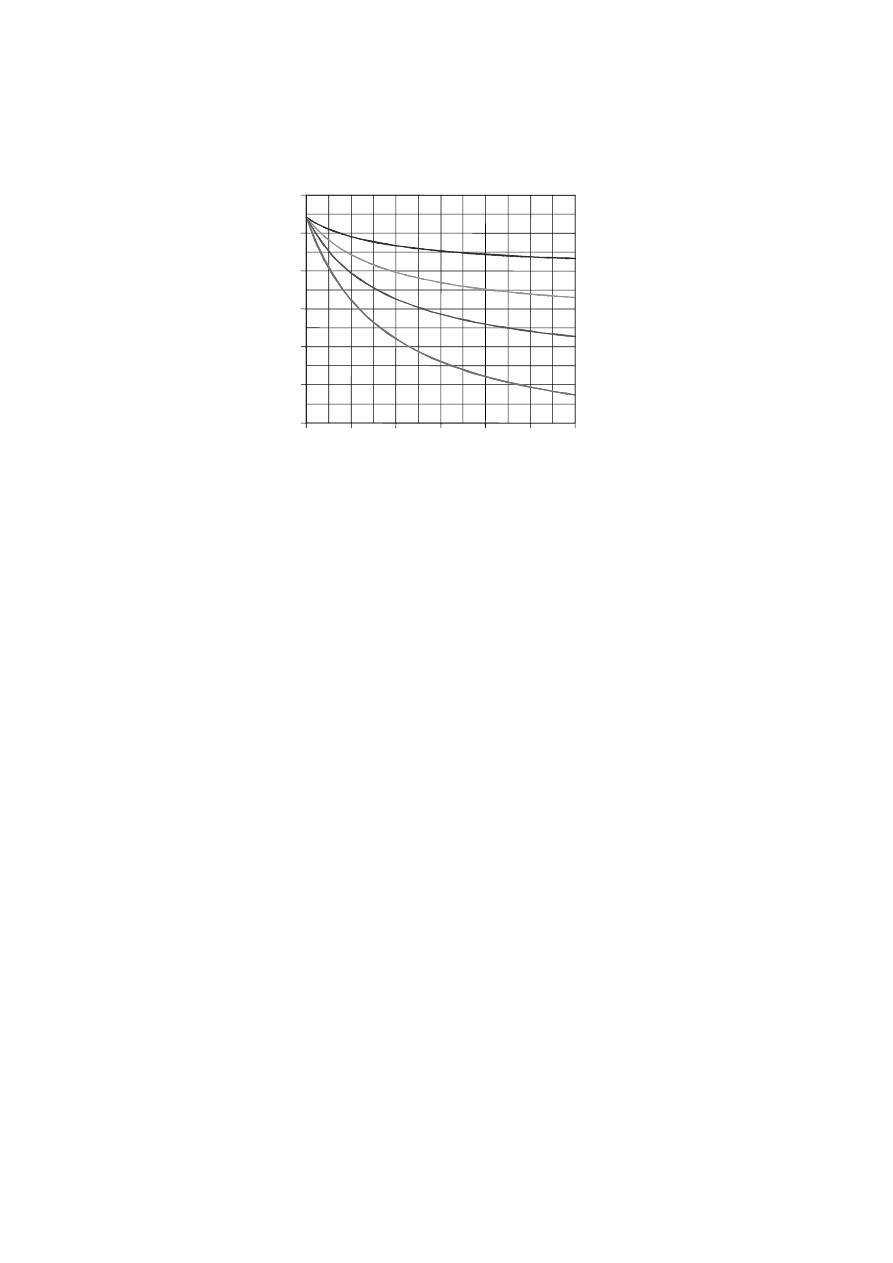
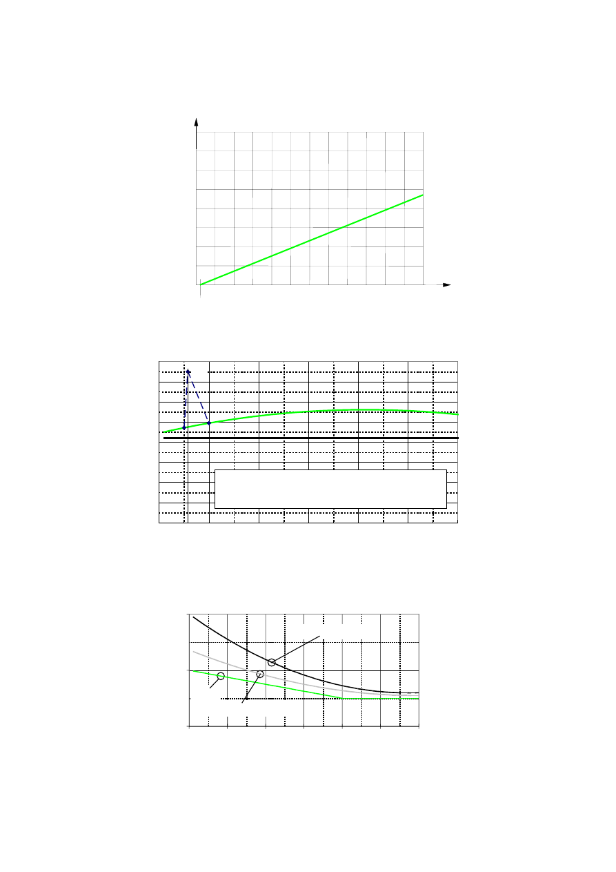
NOTE 1: An example of the variation of the reduction factor
η
fi
versus the load ratio Q
k,1
/G
k
for different
values of the combination factor
ψ
fi
=
ψ
1,1
according to expression (2.5), is shown in Figure 2.1 with
the following assumptions:
γ
G
= 1,35 and
γ
Q
= 1,5. Partial factors are specified in the relevant
National Annexes of EN 1990. Equations (2.5a) and (2.5b) give slightly higher values.
NOTE 2: As a simplification the recommended value of
η
fi
= 0,65 may be used, except for imposed loads
according to load category E as given in EN 1991-1-1 (areas susceptible to accumulation of goods,
including access areas), where the recommended value is 0,7.
Page 30
Draft prEN1994-1-2:2003
3,0
0,0
0,5
1,0
1,5
2,0
2,5
0,2
0,3
0,4
0,5
0,6
0,7
0,8
Q / G
k,1 k
η
fi
1,1
ψ
= 0,7
1,1
ψ
= 0,9
1,1
ψ
= 0,5
1,1
ψ
= 0,2
Figure 2.1: Variation of the reduction factor
η
fi
with the load ratio Q
k,1
/
G
k
(4) Only the effects of thermal deformations resulting from thermal gradients across the cross-section
need be considered. The effects of axial or in-plain thermal expansions may be neglected.
(5) The boundary conditions at supports and ends of member may be assumed to remain unchanged
throughout the fire exposure.
(6) Tabulated data, simplified or advanced calculation models given in clauses 4.2, 4.3 and 4.4
respectively are suitable for verifying members under fire conditions.
2.4.3 Analysis of part of the structure
(1) The effect of actions should be determined for time t = 0 using combination factors
ψ
1
,
1
or
ψ
1
,
2
according to 4.3.1(2) of EN 1991-1-2.
(2) As an alternative to carrying out a global structural analysis for the fire situation (see 2.4.4), the reactions
at supports and internal forces and moments at boundaries of part of the structure may be obtained from a
global structural analysis for normal temperature.
(3) The part of the structure to be analysed should be specified on the basis of the potential thermal
expansions and deformations such, that their interaction with other parts of the structure can be
approximated by time-independent support and boundary conditions during fire exposure.
(4)P Within the part of the structure to be analysed, the relevant failure mode in fire exposure, the
temperature-dependent material properties and member stiffnesses, effects of thermal expansions and
deformations (indirect fire actions) shall be taken into account.
(5) The boundary conditions at supports and forces and moments at boundaries of part of the structure,
may be assumed to remain unchanged throughout the fire exposure.
2.4.4 Global structural analysis
(1)P When a global structural analysis for the fire situation is carried out, the relevant failure mode in fire
exposure, the temperature-dependent material properties and member stiffnesses as well as the effects
of thermal expansions and deformations (indirect fire actions) shall be taken into account.

Page 31
Draft prEN1994-1-2:2003
Section 3
Material properties
3.1 General
(1)P In fire conditions the temperature dependent properties shall be taken into account.
(2) The thermal and mechanical properties of steel should be determined in general from chapter 3 of
EN 1993-1-2.
NOTE:
For reinforcing steels see 3.2.3.
(3) The thermal and mechanical properties of concrete should be determined in general from chapter 3 of
EN 1992-1-2.
NOTE:
For normal weight concrete and light weight concrete see also 3.3.1 and 3.3.2
(4) The mechanical properties of steel at normal temperature (20
°C) should be taken as those given in
EN 1993-1-1 for normal temperature design.
(5) The mechanical properties of concrete, reinforcing and prestressing steel at normal temperature
(20°C) should be taken as those given in EN 1992-1-1 for normal temperature design.
3.2 Mechanical
properties
3.2.1 Strength and deformation properties of structural steel
(1) In case of thermal actions according to section 3.3 of EN 1991-1-2 (natural fire models), particularly
when considering the decreasing temperature branch, the values specified in Table 3.1 of EN 1993-1-2,
for the stress-strain relationships of structural steel, may be used as a sufficiently precise approximation.
3.2.2 Strength and deformation properties of concrete
(1)The parameters specified in Table 3.1 of EN 1992-1-2 hold for siliceous concrete qualities. For
calcareous concrete qualities the same parameters may be used, which is normally on the safe side. If a
more precise information is needed, reference is made to Table 3.1 of EN 1992-1-2.
(2) In case of thermal actions according to section 3.3 of EN 1991-1-2 (natural fire models), particularly
when considering the decreasing temperature branch, the mathematical model for stress-strain
relationships of concrete specified in Figure 3.1 of EN 1992-1-2 should be modified.
NOTE:
As concrete, which has cooled down after having been heated, does not recover its initial
compressive strength, the proposal of informative Annex A may be used in an advanced calculation
model according to 4.4.1.
(3) The tensile strength of concrete may be assumed to be zero, which is on the safe side.
(4) If tensile strength is taken into account in verifications carried out with an advanced calculation model,
it should not exceed the values given in 3.2.2.2 of EN 1992-1-2.

Page 32
Draft prEN1994-1-2:2003
3.2.3 Reinforcing
steels
(1) The strength and deformation properties of reinforcing steels at elevated temperatures may be
obtained by the same mathematical model as that presented in Table 3.1 of EN 1993-1-2.
(2) The three main parameters for hot rolled reinforcing steel may be given by Annex A of EN 1993-1-2,
provided that
θ
,
u
f
is limited by 1,1.
θ
,
y
f
.
(3) The three main parameters for cold worked reinforcing steel are given in Table 3.2a of EN 1992-1-2.
NOTE:
Prestressing steels will normally not be used in composite structures.
(4) In case of thermal actions according to 3.3 of EN 1991-1-2 (natural fire models), particularly when
considering the decreasing temperature branch, the values specified in Table 3.1 of EN 1993-1-2 for the
stress-strain relationships of structural steel, may be used as a sufficiently precise approximation for hot
rolled reinforcing steel.
3.3
Thermal properties
3.3.1
Normal weight concrete
(1) The specific heat cc of normal weight dry, siliceous or calcareous concrete given in 3.3.2(1) of
EN 1992-1-2 may be approximated by:
(
)
(
)
2
c
c
,
c
100
/
4
,
3
100
/
2
,
56
890
c
θ
θ
θ
−
+
=
(3.1a)
(2) The variation of the specific heat with temperature is illustrated in Figure 3.2.
(3) In simple calculation models (see 4.3) the specific heat may be considered to be independent of the
concrete temperature. In this case the following value should be taken:
1000
c
c
=
[J/kg K]
(3.1b)
(4) The moisture content of concrete should be taken equal to the equilibrium moisture content. If these
data are not available, moisture content should not exceed 4 % of the concrete weight.
(5) Where the moisture content is not considered on the level of the heat balance, the equation given
in (1) for the specific heat may be completed by a peak value, shown in Figure 3.2, situated between
100°C and 200°C such as at 115ºC:
2020
c
*
c
=
for a moisture content of 3% of concrete weight and
[J/kg K]
(3.1c)
5600
c
*
c
=
for a moisture content of 10% of concrete weight.
[J/kg K]
(3.1d)
The last situation may occur for hollow sections filled with concrete.
(6) The thermal conductivity
c
λ
of normal weight concrete may be determined between the lower and
upper limits given in (7).
NOTE 1: The value of thermal conductivity may be set by the National Annex within the range defined by the
lower and upper limits.
NOTE 2: The upper limit has been derived from tests of steel-concrete composite structural elements.
The use of the upper limit is recommended.
Page 33
Draft prEN1994-1-2:2003
0
200
400
600
800
1000
1200
(°C)
20°C
16
12
8
4
0
LC
c
θ
(∆l/l)x10
3
Figure 3.1: Related thermal elongation of light weight concrete (LC) as a function of the
temperature
0
200
400
600
800
1000
1200
1400
1600
0
200
400
600
800
1000
1200
θ
c
(°C)
c
c
(J/kg K)
C
c
= 2020 J/kg K for a humidity of 3% of concrete weight
C
c
= 5600 J/kg K for a humidity of 10% of concrete weight
C
c
*
*
*
115
LC
NC
Figure 3.2: Specific heat of normal weight concrete (NC) and light weight concrete (LC) as a
function of the temperature
0
1
2
0
200
400
600
800
1000 1200
θ
c
(°C)
λ
c
(W/m K)
NC /UPPER LIMIT
NC /LOWER LIMIT
LC
Figure 3.3: Thermal conductivity of normal weight concrete (NC) and light weight concrete (LC)
as a function of the temperature

Page 34
Draft prEN1994-1-2:2003
(7) The upper limit of thermal conductivity
c
λ
of normal weight concrete may be determined from:
(
)
(
)
2
c
c
c
100
/
0107
,
0
100
/
2451
,
0
2
θ
θ
λ
+
−
=
[W/mK] for 20°C ≤
θc ≤ 1200°C (3.2a)
where
θc is the concrete temperature.
The lower limit of thermal conductivity
c
λ
of normal weight concrete may be determined from:
(
)
(
)
2
c
c
c
100
/
0057
,
0
100
/
136
,
0
36
,
1
θ
θ
λ
+
−
=
[W/mK] for 20°C ≤
θc ≤ 1200°C (3.2b)
where
θc is the concrete temperature.
(8) The variation of the thermal conductivity with temperature is illustrated in Figure 3.3.
(9) In simple calculation models (see 4.3) the thermal conductivity may be considered to be independent
of the concrete temperature. In this case the following value should be taken:
60
,
1
c
=
λ
[W/mK]
(3.2c)
3.3.2
Light weight concrete
(1) The related thermal elongation
l
/
l
∆
of light weight concrete may be determined from:
(
)
20
10
.
8
l
/
l
c
6
−
=
−
θ
∆
(3.3)
where:
l
is the length at room temperature of the light weight concrete member
l
∆
is the temperature induced elongation of the light weight concrete member
c
θ
is the light weight concrete temperature [°C].
(2) The specific heat
c
c
of light weight concrete may be considered to be independent of the concrete
temperature:
840
c
c
=
[J/kg K]
(3.4)
(3) The thermal conductivity
c
λ
of light weight concrete may be determined from the following:
(
)
1600
/
0
,
1
c
c
θ
λ
−
=
[W/mK]
for 20°C
≤
θc ≤ 800°C
(3.5a)
5
,
0
c
=
λ
[W/mK]
for
θc > 800°C
(3.5b)
(4) The variation with temperature of the related thermal elongation, the specific heat and the thermal
conductivity are illustrated in Figures 3.1, 3.2 and 3.3.
(5) The moisture content of concrete should be taken equal to the equilibrium moisture content. If these
data are not available, the moisture content should not exceed 5 % of the concrete weight.

Page 35
Draft prEN1994-1-2:2003
3.3.3
Fire protection materials
(1)P The properties and performance of fire protection materials shall be assessed using the test
procedures given in ENV 13381-1, ENV 13381-2, ENV 13381-5 and ENV 13381-6
3.4
Density
(1)P The density of steel
a
ρ
shall be considered to be independent of the steel temperature. The
following value shall be taken:
7850
a
=
ρ
[kg/m
3
]
(3.6)
(2) For static loads, the density of concrete
c
ρ
may be considered to be independent of the concrete
temperature. For calculation of the thermal response, the variation of
c
ρ
in function of the temperature
may be considered according to 3.3.2(3) of EN 1992-1-2.
NOTE:
The variation of
c
ρ
in function of the temperature may be approximated by
(
)
100
/
47
,
23
2354
c
,
c
θ
ρ
θ
−
=
(3.7a)
(3) For unreinforced normal weight concrete (NC) the following value may be taken:
2300
NC
,
c
=
ρ
[kg/m
3
]
(3.7b)
(4)P The density of unreinforced light weight concrete (LC), considered in this Part 1-2 of EN 1994 for
structural fire design, shall be in the range of:
2000
to
1600
LC
,
c
=
ρ
[kg/m
3
]
(3.7c)

Page 36
Draft prEN1994-1-2:2003
Section 4
Design procedures
4.1
Introduction
(1)P The assessment of structural behaviour in a fire design situation shall be based on the requirements
of section 5, Constructional details, and on one of the following approaches:
- recognized design solutions called tabulated data for specific types of structural members;
- simple calculation models for specific types of structural members;
- advanced calculation models for simulating the behaviour of the global structure (see 2.4.4), of parts
of the structure (see 2.4.3) or only of a structural member (see 2.4.2).
(2)P Application of tabulated data and simple calculation models is confined to individual structural
members, considered as directly exposed to fire over their full length. Thermal action is taken in
accordance with standard fire exposure, and the same temperature distribution is assumed to exist along
the length of the structural members. Extrapolation outside the range of experimental evidence is not
allowed.
(3) Tabulated data and simple calculation models should give conservative results compared to relevant
tests or advanced calculation models.
(4)P Application of advanced calculation models deals with the response to fire of structural members,
subassemblies or complete structures and allows - where appropriate - the assessment of the interaction
between parts of the structure which are directly exposed to fire and those which are not exposed.
(5)P In advanced calculation models, engineering principles shall be applied in a realistic manner to
specific applications.
(6)P Where no tabulated data nor simple calculation models are applicable, it is necessary to use either a
method based on an advanced calculation model or a method based on test results.
(7)P Load levels are defined by the ratio between the relevant design effect of actions and the design
resistance:
0
,
1
R
E
d
d
≤
=
η
; load level referring to EN 1994-1-1,
(4.1)
where:
d
E
is the design effect of actions for normal temperature design and
d
R
is the design resistance for normal temperature design;
d
t,
d
,
fi
t,
fi
R
E
=
η
; load level for fire design,
where:
t,
d
,
fi
E
is the design effect of actions in the fire situation, at time t.
(8)P For a global structural analysis (entire structures) the mechanical actions shall be combined using
the accidental combination given in 4.3 of EN 1991-1-2.

Page 37
Draft prEN1994-1-2:2003
(9)P For any type of structural analysis according to 2.4.2, 2.4.3 and 2.4.4, load bearing failure "R" is
reached, when the design resistance in the fire situation
t,
d
,
fi
R
has decreased to the level of the design
effect of actions in the fire situation
t,
d
,
fi
E
such as
t,
d
,
fi
R
=
t,
d
,
fi
E
(10) For the design model "Tabulated data" of 4.2,
t,
d
,
fi
R
may be calculated by
d
t,
fi
t,
d
,
fi
R
R
η
=
.
(11) The simple calculation models for slabs and beams may be based on known temperature
distributions through the cross-section, as given in 4.3 and on material properties, as given in section 3.
(12) For slabs and beams where temperature distributions are determined by other appropriate methods
or by tests, the resistance of the cross-sections may be calculated directly using the material properties
given in section 3, provided instability or other premature failure effects are prevented.
(13) For a beam connected to a slab, the resistance to longitudinal shear provided by transverse
reinforcement should be determined from 6.6.6, of EN 1994-1-1. In this case the contribution of the
profiled steel sheeting should be ignored when its temperature exceeds 350°C. The effective width
eff
b
at elevated temperatures may be taken as the value in 5.4.1.2 of EN 1994-1-1.
(14) Rule (13) holds if the axis distance of these transverse reinforcements satisfies column 3 in
Table 5.8 of EN 1992-1-2.
(15) In this document, columns subjected to fire conditions are assumed to be equally heated all around
their cross-section, whereas beams supporting a floor are supposed to be heated only from the three
lower sides.
(16) For beams connected to slabs with profiled steel sheets a three side fire exposure may be assumed,
when at least 85 % of the upper side of the steel profile is directly covered by the steel sheet.
4.2
Tabulated data
4.2.1
Scope of application
(1) The following rules refer to member analysis according to 2.4.2. They are only valid for the standard
fire exposure.
(2) The data given hereafter depend on the load level
t,
fi
η
following (7)P, (9)P and (10) of 4.1.
(3) The design effect of actions in the fire situation supposed to be time-independent may be taken as
d
,
fi
E
according to (2) of 2.4.2.
(4)P It shall be verified that
t,
d
,
fi
E
≤
t,
d
,
fi
R
(5) For the tabulated data given in the Tables 4.1 to 4.7, linear interpolation is permitted for all physical
parameters.
NOTE:
When at present classification is impossible, this is marked by "-" in the tables.

Page 38
Draft prEN1994-1-2:2003
4.2.2
Composite beam comprising steel beam with partial concrete encasement
(1) Composite beams comprising a steel beam with partial concrete encasement (Figure 1.5) may be
classified in function of the load level
t,
fi
η
, the beam width b and the additional reinforcement As
related to the area of bottom flange Af as given in Table 4.1.
(2) The values given in Table 4.1 are valid for simply supported beams.
(3) When determining
d
R
and
d
t,
fi
t,
d
,
fi
R
R
η
=
in connection with Table 4.1, the following conditions
should be observed:
- the thickness of the web ew does not exceed 1/15 of the width b;
- the thickness of the bottom flange ef does not exceed twice the thickness of the web ew;
- the thickness of the concrete slab hc is at least 120 mm;
- the additional reinforcement area related to the total area between the flange
(
)
s
c
s
A
A
/
A
+
does
not exceed 5 %;
- the value of
d
R
is calculated on the basis of EN 1994-1-1 provided that:
the effective slab width
eff
b
does not exceed 5 m,
the additional reinforcement
s
A
is not taken into account.
(4) The values given in Table 4.1 are valid for the structural steel grade S355. If another structural steel
grade is used, the minimum values for the additional reinforcement given in Table 4.1 should be factored
by the ratio of the yield point of this other steel grade to the yield point of grade S355.
(5) The values given in Table 4.1 are valid for the steel grade S500 used for the additional reinforcement
As.
(6) The values given in Tables 4.1 and 4.2 are valid for beams connected to flat reinforced concrete
slabs.
(7) The values given in Tables 4.1 and 4.2 may be used for beams connected to composite floors with
profiled steel sheets, if at least 85 % of the upper side of the steel profile is directly covered by the steel
sheet. If not, void fillers have to be used on top of the beams.
(8) The material used for void fillers should be suitable for fire protection of steel (see ENV 13381-4
and/or ENV 13381-5).
(9) Additional reinforcement has to be placed as close as possible to the bottom flange taking into
account the axis distances u
1
and u
2
of Table 4.2 .
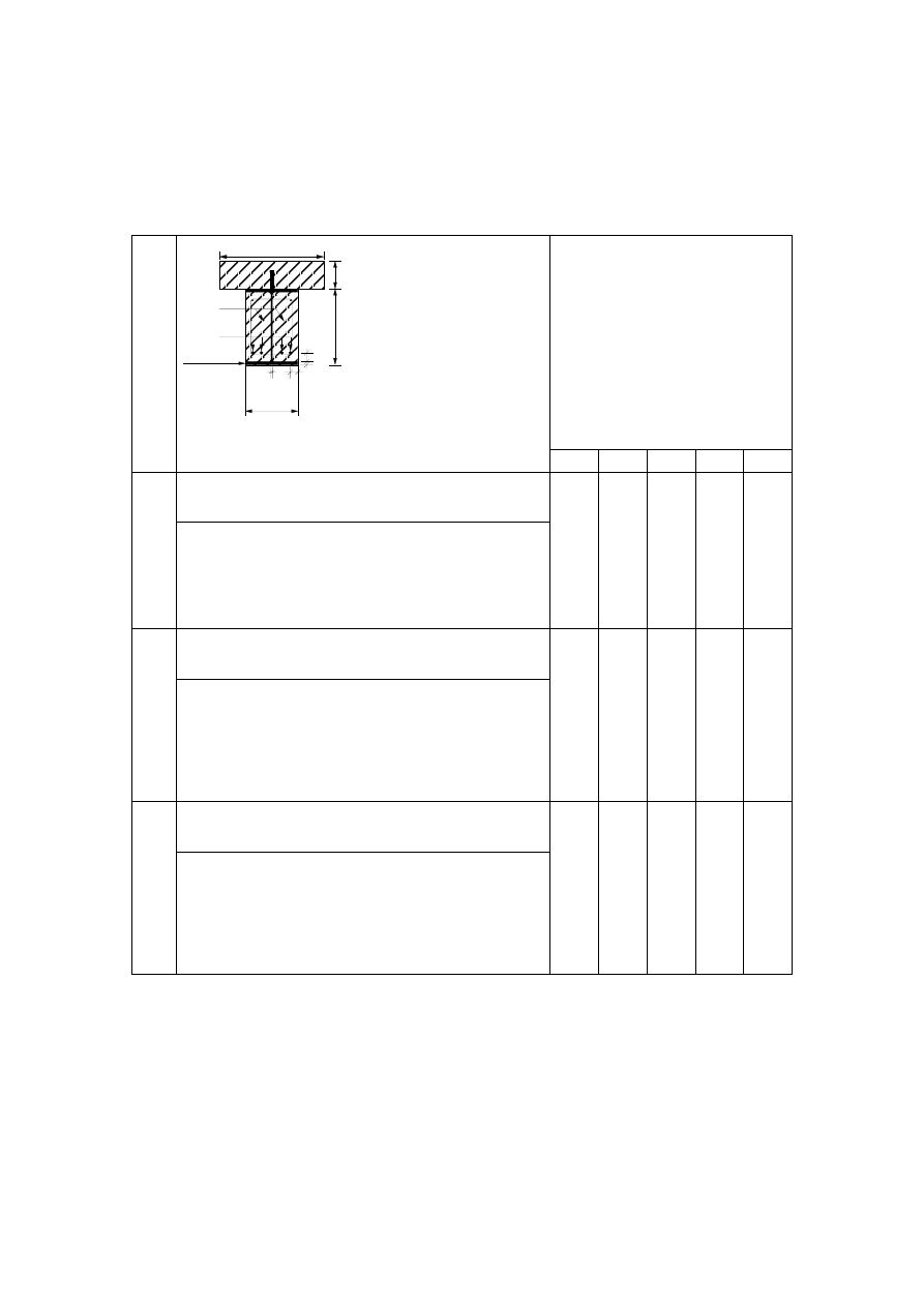
Page 39
Draft prEN1994-1-2:2003
Table 4.1:
Minimum cross-sectional dimensions b and minimum additional reinforcement in
relation to the area of flange As / Af, for composite beams comprising steel beams
with partial concrete encasement.
u
2
u
1
e
w
e
f
b
A
f
= b x e
f
A
s
A
c
h
h
c
b
eff
Condition for application:
slab: h
c
≥ 120 mm
b
eff
≤ 5 m
steel section: b / e
w
≥ 15
e
f
/ e
w
≤ 2
additional reinforcement
area, related to total area
between the flanges:
A
s
/(A
c
+ A
s
)
≤ 5%
Standard Fire Resistance
R30 R60 R90 R120 R180
1
Minimum cross-sectional dimensions for load level
η
fi,t
≤ 0,3
min b [mm] and additional reinforcement As in relation to
the area of flange As / Af
1.1
1.2
1.3
h
≥
0,9
×
min b
h
≥
1,5
×
min b
h
≥
2,0
×
min b
70/0,0
60/0,0
60/0,0
100/0,0
100/0,0
100/0,0
170/0,0
150/0,0
150/0,0
200/0,0
180/0,0
180/0,0
260/0,0
240/0,0
240/0,0
2
Minimum cross-sectional dimensions for load level
η
fi,t
≤ 0,5
min b [mm] and additional reinforcement As in relation to
the area of flange As / Af
2.1
2.2
2.3
2.4
h
≥
0,9
×
min b
h
≥
1,5
×
min b
h
≥
2,0
×
min b
h
≥
3,0
×
min b
80/0,0
80/0,0
70/0,0
60/0,0
170/0,0
150/0,0
120/0,0
100/0,0
250/0,4
200/0,2
180/0,2
170/0,2
270/0,5
240/0,3
220/0,3
200/0,3
-
300/0,5
280/0,3
250/0,3
3
Minimum cross-sectional dimensions for load level
η
fi,t
≤ 0,7
min b [mm] and additional reinforcement As in relation to
the area of flange As / Af
3.1
3.2
3.3
3.4
h
≥
0,9
×
min b
h
≥
1,5
×
min b
h
≥
2,0
×
min b
h
≥
3,0
×
min b
80/0,0
80/0,0
70/0,0
70/0,0
270/0,4
240/0,3
190/0,3
170/0,2
300/0,6
270/0,4
210/0,4
190/0,4
-
300/0,6
270/0,5
270/0,5
-
-
320/1,0
300/0,8
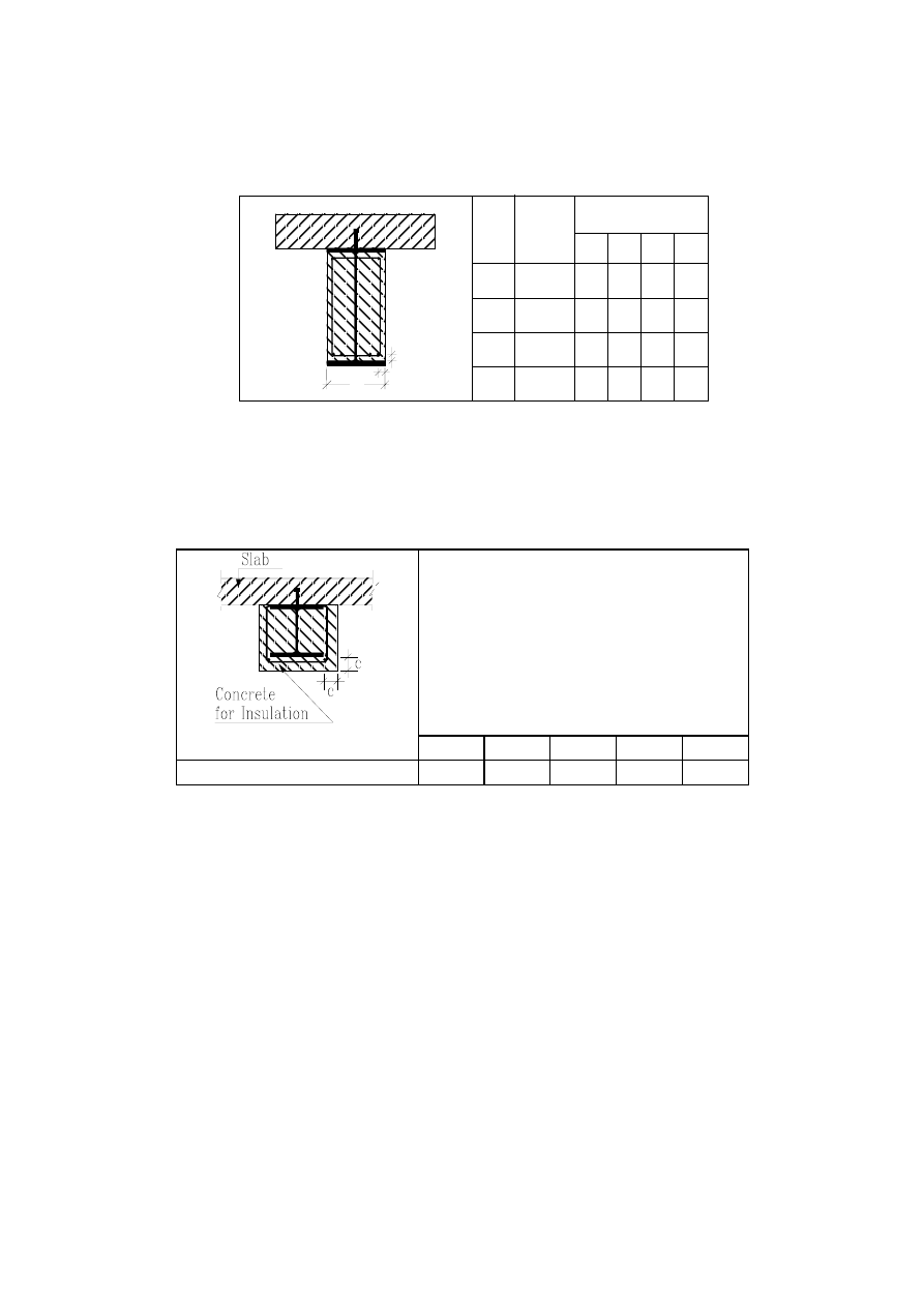
Page 40
Draft prEN1994-1-2:2003
Table 4.2: Minimum axis distance for additional reinforcement of composite beams.
b
u
1
u
2
Standard Fire
Resistance
Min. Axis
Distance
[mm]
Profile
Width
b [mm]
> 300
250
200
170
u
1
u
2
u
2
u
2
u
1
u
1
u
1
u
2
100 120
-
-
-
-
60
45
35
40
(25)
50
50
45
60
70
60
80
100 120
-
40
55
60
-
60
75
90
120
60
90
60
R180
R120
R90
R60
_
NOTE:
These values have to be checked according to 4.4.1.2 of EN 1992-1-1 (see
*)
(10) If the concrete encasing the steel beam has only an insulation function, the fire resistance R30 to
R180 may be fulfilled for a concrete cover c of the steel section according to Table 4.3.
NOTE:
For R30, concrete need only be placed between the flanges of the steel section.
Table 4.3
Standard Fire Resistance
R30
R60
R90
R120
R180
Concrete cover c [mm]
0
25
30
40
50
(11) Where concrete encasing has only an insulation function, fabric reinforcement should be placed
according to 5.1(6), except for R30.
4.2.3
Composite columns
4.2.3.1 General
(1) The design Tables 4.4, 4.6 and 4.7 are valid for braced frames.
(2) Load levels
t,
fi
η
in Tables 4.6 and 4.7 are defined by 4.1(7)P assuming pin-ended supports of the
column for the calculation of
d
R
, provided that both column ends are rotationally restrained in the fire
situation. This is generally the case in practice according to Figures 5.3 to 5.6. Continuous columns may
also be assumed to be efficiently restrained at the affected end sections under fire conditions.
(3) When using Tables 4.6 and 4.7,
d
R
has to be based on twice the buckling length used in the fire
design situation.
(4) Tables 4.4 to 4.7 are valid both for concentric axial or eccentric loads applied to columns. When
determining
d
R
, the design resistance for normal temperature design, the eccentricity of the load should
be considered.
25*
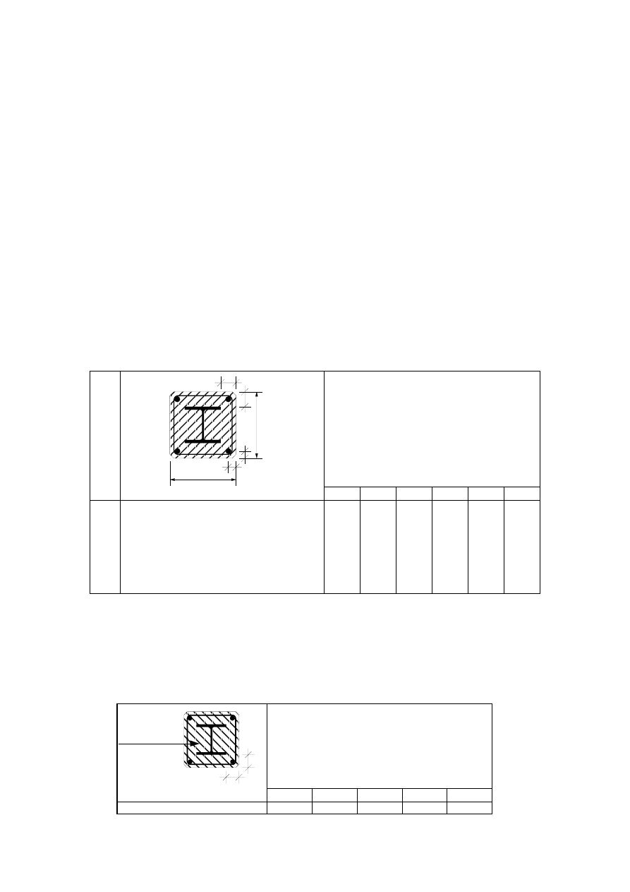
Page 41
Draft prEN1994-1-2:2003
(5) The tabulated data given in Tables 4.4 to 4.7 are valid for columns with a maximum length of 30 times
the minimum external dimension of the cross-section chosen.
4.2.3.2 Composite columns made of totally encased steel sections
(1) Composite columns made of totally encased steel sections may be classified in function of the depth
bc or hc, the concrete cover c of the steel section and the minimum axis distance us of the reinforcing
bars as given by the two alternative solutions in Table 4.4.
(2) All load levels
t,
fi
η
may be used when applying (10) of 4.1.
(3) The reinforcement should consist of a minimum of 4 bars with a diameter of 12 mm. In all cases the
minimum percentage of longitudinal reinforcing bars should fulfil the requirements of EN 1994-1-1.
(4) The maximum percentage of longitudinal reinforcing bars should fulfil the requirements of
EN 1994-1-1. For stirrups it should be referred to EN 1992-1-1.
Table 4.4: Minimum cross-sectional dimensions, minimum concrete cover of the steel section and
minimum axis distance of the reinforcing bars, of composite columns made of totally
encased steel sections.
b
c
u
s
u
s
h
c
c
c
Standard Fire Resistance
R30
R60
R90
R120
R180
R240
1.1
1.2
1.3
Minimum dimensions hc and bc [mm]
minimum concrete cover of steel section c [mm]
minimum axis distance of reinforcing bars us [mm]
150
40
20*
180
50
30
220
50
30
300
75
40
350
75
50
400
75
50
Or
2.1
2.2
2.3
Minimum dimensions hc and bc [mm]
minimum concrete cover of steel section c [mm]
minimum axis distance of reinforcing bars us [mm]
-
-
-
200
40
20*
250
40
20*
350
50
30
400
60
40
-
-
-
NOTE:
These values have to be checked according to 4.4.1.2 of EN 1992-1-2 (see
*).
(5) If the concrete encasing the steel section has only an insulation function, when designing the column
for normal temperature design, the fire resistance R30 to R180 may be fulfilled for a concrete cover c of
the steel section according to Table 4.5.
NOTE:
For R30, concrete need only be placed between the flanges of the steel section.
Table 4.5
Concrete
for Insulation
c
c
Standard Fire Resistance
R30
R60
R90
R120
R180
Concrete cover c [mm]
0
25
30
40
50
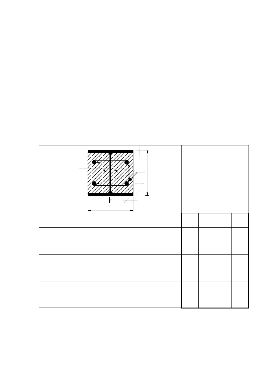
Page 42
Draft prEN1994-1-2:2003
(6) Where concrete encasing has only an insulation function, fabric reinforcement should be placed
according to 5.1(6), except for R30.
4.2.3.3 Composite columns made of partially encased steel sections
(1) Composite columns made of partially encased steel sections may be classified in function of the load
level
ηfi,t, the depth b or h, the minimum axis distance of the reinforcing bars us and the ratio between
the web thickness ew and the flange thickness ef as given in Table 4.6.
(2) When determining
d
R
and
d
t,
fi
t,
d
,
fi
R
R
η
=
, in connection with Table 4.6, reinforcement ratios
(
)
s
c
s
A
A
/
A
+
higher than 6 % or lower than 1 %, should not be taken into account.
(3) Table 4.6 may be used for the structural steel grades S 235, S 275 and S 355.
Table 4.6: Minimum cross-sectional dimensions, minimum axis distance and minimum
reinforcement ratios of composite columns made of partially encased steel sections.
A
c
A
s
u
s
u
s
w
e
f
e
b
h
Standard Fire Resistance
R30
R60
R90
R120
Minimum ratio of web to flange thickness e
w
/e
f
0,5
0,5
0,5
0,5
1
Minimum cross-sectional dimensions for load level
η
fi,t
≤ 0,28
1.1
1.2
1.3
minimum dimensions h and b [mm]
minimum axis distance of reinforcing bars us [mm]
minimum ratio of reinforcement A
s
/(A
c
+A
s
) in %
160
-
-
200
50
4
300
50
3
400
70
4
2
Minimum cross-sectional dimensions for load level
η
fi,t
≤ 0,47
2.1
2.2
2.3
minimum dimensions h and b [mm]
minimum axis distance of reinforcing bars us [mm]
minimum ratio of reinforcement A
s
/(A
c
+A
s
) in %
160
-
-
300
50
4
400
70
4
-
-
-
3
Minimum cross-sectional dimensions for load level
η
fi,t
≤ 0,66
3.1
3.2
3.3
minimum dimensions h and b [mm]
minimum axis distance of reinforcing bars us [mm]
minimum ratio of reinforcement A
s
/(A
c
+A
s
) in %
160
40
1
400
70
4
-
-
-
-
-
-
NOTE:
The values of the load level
t,
fi
η
have been reduced by 5%, compared to ENV values, following
the new procedure in EN 1994-1-1.
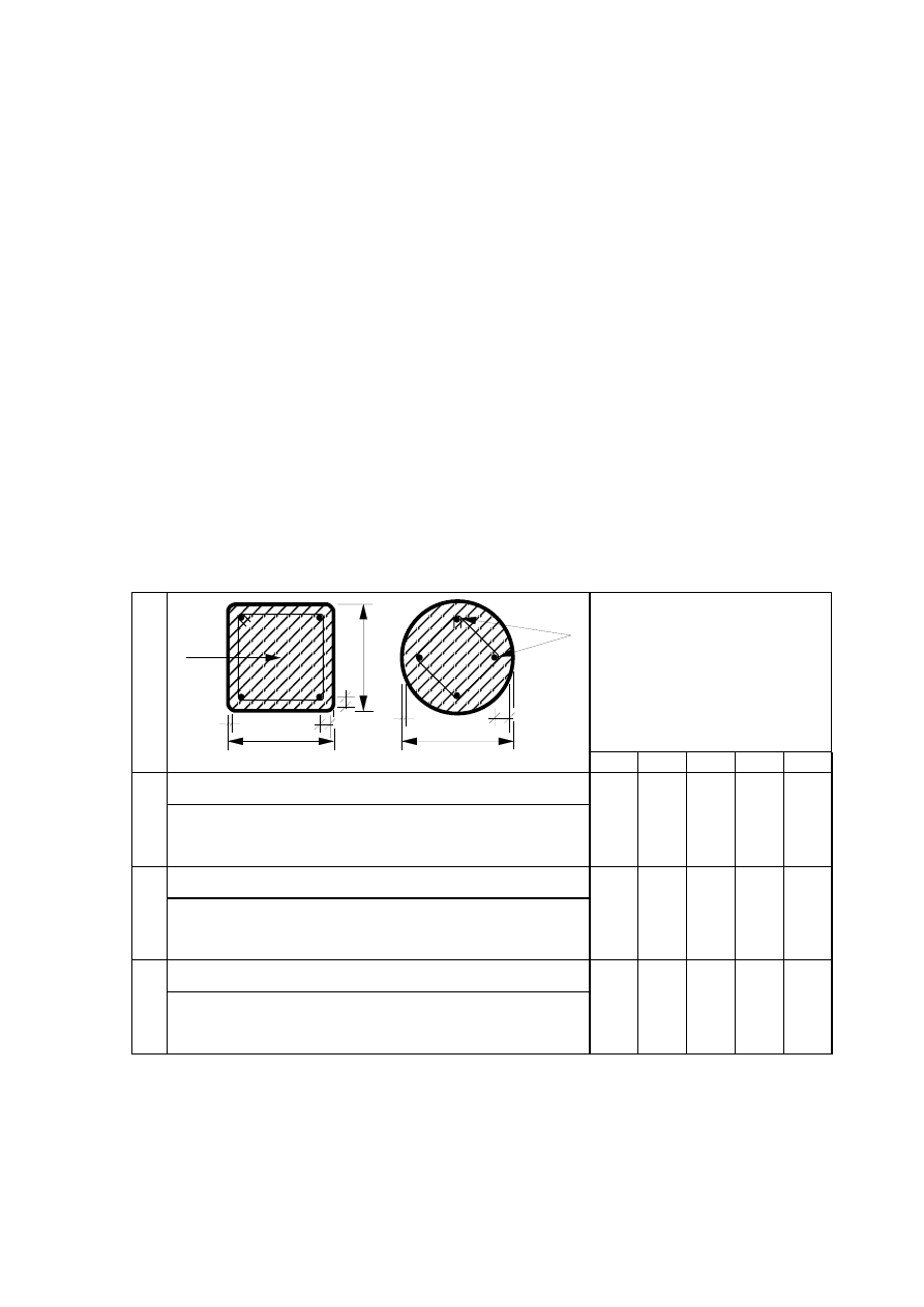
Page 43
Draft prEN1994-1-2:2003
4.2.3.4 Composite columns made of concrete filled hollow sections
(1) Composite columns made of concrete filled hollow sections may be classified as a function of the load
level
t,
fi
η
, the cross-section size b, h or d, the ratio of reinforcement As / (Ac + As) and the minimum axis
distance of the reinforcing bars us according to Table 4.7.
(2) When calculating
d
R
and
d
t,
fi
t,
d
,
fi
R
R
η
=
, in connection with Table 4.7, following rules apply:
- irrespective of the steel grade of the hollow sections, a nominal yield point of 235 N/mm² is taken into
account;
- the wall thickness e of the hollow section is considered up to a maximum of 1/25 of b or d;
- reinforcement ratios
(
)
s
c
s
A
A
/
A
+
higher than 3 % are not taken into account and
- the concrete strength is considered as for normal temperature design.
(3) The values given in Table 4.7 are valid for the steel grade S 500 used for the reinforcement
s
A
.
Table 4.7: Minimum cross-sectional dimensions, minimum reinforcement ratios and minimum axis
distance of the reinforcing bars of composite columns made of concrete filled hollow
sections
b
A
c
e
e
u
s
u
s
u
s
d
A
s
h
Standard Fire Resistance
steel section: (b / e)
≥ 25 or (d / e) ≥ 25
R30
R60
R90
R120 R180
1
Minimum cross-sectional dimensions for load level
η
fi,t
≤ 0,28
1.1
1.2
1.3
Minimum dimensions h and b or minimum diameter d [mm]
Minimum ratio of reinforcement As / (Ac + As) in (%)
Minimum axis distance of reinforcing bars us [mm]
160
0
-
200
1,5
30
220
3,0
40
260
6,0
50
400
6,0
60
2
Minimum cross-sectional dimensions for load level
η
fi,t
≤ 0,47
2.1
2.2
2.3
Minimum dimensions h and b or minimum diameter d [mm]
Minimum ratio of reinforcement As / (Ac + As) in (%)
Minimum axis distance of reinforcing bars us [mm]
260
0
-
260
3,0
30
400
6,0
40
450
6,0
50
500
6,0
60
3
Minimum cross-sectional dimensions for load level
η
fi,t
≤ 0,66
3.1
3.2
3.3
Minimum dimensions h and b or minimum diameter d [mm]
Minimum ratio of reinforcement As / (Ac + As) in (%)
Minimum axis distance of reinforcing bars us [mm]
260
3,0
25
450
6,0
30
550
6,0
40
-
-
-
-
-
-
NOTE:
The values of the load level
t,
fi
η
have been reduced by 5%, compared to ENV values, following
the new procedure in EN 1994-1-1.

Page 44
Draft prEN1994-1-2:2003
4.3
Simple Calculation Models
4.3.1
General rules for composite slabs and composite beams
(1) The following rules refer to member analysis according to 2.4.2. They are only valid for the standard
fire exposure.
(2) Rules that are common to composite slabs and composite beams are given in this section. In addition,
rules for slabs are given in 4.3.2 and 4.3.3 and for composite beams are given in 4.3.4.
(3)P For composite beams in which the effective section is Class 1 or Class 2 (see EN 1993-1-1), and for
composite slabs, the design bending resistance shall be determined by plastic theory.
(4) The plastic neutral axis of a composite slab or composite beam may be determined from:
0
f
k
A
f
k
A
m
1
j
c
,
fi
,
M
j
c,
j
,
c,
j
slab
n
1
i
a
,
fi
,
M
i,
y
i,
max,
i
=
+
∑
∑
=
=
γ
α
γ
θ
θ
(4.2)
where:
slab
α
is the coefficient taking into account the assumption of the rectangular stress block when designing
slabs,
α
slab
= 0,85
.
i,
y
f
is the nominal yield strength
y
f
for the elemental steel area
i
A
, taken as positive on the
compression side of the plastic neutral axis and negative on the tension side;
j
,
c
f
is the design strength for the elemental concrete area
j
A
at 20°C.
For concrete parts tension is
ignored;
i,
max,
k
θ
or
j
,
c,
k
θ
are as defined in Table 3.1 of EN 1993-1-2 or Table 3.1 of EN 1992-1-2 .
(5) The design moment resistance
Rd
t,
fi,
M
may be determined from:
∑
∑
=
=
+
=
m
1
j
c
,
i
f
M,
j
c,
j
,
,
c
j
j
slab
n
1
i
if
M,
i
y,
i,
,
max
i
i
Rd
t,
fi,
f
k
z
A
f
k
z
A
M
γ
α
γ
θ
θ
(4.3)
where:
j
i
z
,
z
is the distance from the plastic neutral axis to the centroid of the elemental area
i
A
or
j
A
.
(6) For continuous composite slabs and beams, the rules of EN 1992-1-2 and EN 1994-1-1 apply in order
to guarantee the required rotation capacity.
4.3.2 Unprotected composite slabs
(1) Typical examples of concrete slabs with profiled steel sheets with or without reinforcing bars are given
in Figure 1.1
(2) The following rules apply to the calculation of the standard fire resistance of both simply supported
and continuous concrete slabs with profiled steel sheets and reinforcement, as described below when
heated from below according to the standard temperature-time curve.

Page 45
Draft prEN1994-1-2:2003
(3) This method is only applicable to directly heated steel sheets not protected by any insulation and to
composite slabs with no insulation between the composite slab and the screed (see Figures 4.1 and 4.2).
NOTE: A method is given in B.4 of Annex B for the calculation of the effective thickness
eff
h
.
steel sheet
h
screed
concrete
eff
h
h
1
3
h
2
l
1
l
3
l
1
l
3
l
2
l
2
h
h
1
3
h
2
Figure 4.1 Figure 4.2
(4) The possible effect on the fire resistance of axial restraint, is not taken into account in the subsequent
rules.
(5) For a design complying with EN 1994-1-1, the fire resistance of composite concrete slabs with profiled
steel sheets, with or without additional reinforcement, is at least 30 minutes, when assessed under the
load bearing criterion "R" according to (1)P of 2.1.2. For means to verify whether the thermal insulation
criterion "I" is fulfilled, see hereafter.
(6) For composite slabs the integrity criterion "E" is assumed to be satisfied.
NOTE 1:
In B.1 of Annex B a method is given for the calculation of the fire resistance with respect to the
criterion of thermal insulation “I”.
NOTE 2:
In B.2 and B.3 of Annex B a method is given for the calculation of the fire resistance with respect
to the criterion of mechanical resistance “R” and in relation to the sagging and hogging moment
resistances.
(7) Light weight concrete defined in 3.3.2 and 3.4 may be used.
(8) The field of application for unprotected composite slabs is given in Table 4.8 for both normal weight
concrete (NC) and light weight concrete (LC). For notations see Figures 4.1 and 4.2.
Table 4.8
for re-entrant steel sheet profiles
77,0 ≤
ℓ
1
≤ 135,0 mm
110,0 ≤
ℓ
2
≤ 150,0 mm
38,5 ≤
ℓ
3
≤ 97,5 mm
30,0 ≤
h
1
≤ 60,0 mm
50,0 ≤
h
2
≤ 130
mm
for trapezoidal steel profiles
80,0 ≤
ℓ
1
≤ 155,0 mm
32,0 ≤
ℓ
2
≤
132,0 mm
40,0 ≤
ℓ
3
≤
115,0 mm
50,0 ≤
h
1
≤
100,0 mm
50,0 ≤
h
2
≤
100,0 mm
4.3.3
Protected composite slabs
(1) An improvement of the fire resistance of the composite slab may be obtained by using a protection
system applied to the steel sheet in order to decrease the heat transfer to the composite slab.
(2) The performance of the protection system used for a composite slab should be assessed according
to:
- ENV 13381-1 as far as suspended ceilings are concerned and
- ENV 13381-5 as far as protection materials are concerned.

Page 46
Draft prEN1994-1-2:2003
(3) The thermal insulation criterion "I" is assessed by deducing from the effective thickness
eff
h
the
equivalent concrete thickness of the protection system (see ENV 13381-5).
(4) The load bearing criterion "R" is fulfilled as long as the temperature of the steel sheet of the composite
slab is lower or equal to 350°C, when heated from below by the standard fire.
4.3.4
Composite beams
4.3.4.1 Structural Behaviour
4.3.4.1.1
General
(1)P Composite beams shall be checked for:
- resistance of critical cross-sections in accordance with 6.1.1(P) of EN 1994-1-1 to bending (4.3.4.1.2);
- vertical shear (4.3.4.1.3);
- resistance to longitudinal shear (4.3.4.1.5).
NOTE: Guidance on critical cross-sections is given in 6.1.1(4)P of EN 1994-1-1.
(2) Where in the fire situation, test evidence (see EN 1365 Part 3) of composite action between the
floor slab and the steel beam is available, beams which for normal conditions are assumed to be
non-composite may be assumed to be composite in fire conditions.
(3) The temperature distribution over the cross-section may be determined from test, advanced
calculation models (4.4.2) or for composite beams comprising steel beams with no concrete encasement,
from the simple calculation model of 4.3.4.2.2.
4.3.4.1.2
Bending resistance of cross-sections of beams
(1) The design bending resistance may be determined by plastic theory for any class of cross sections
except for class 4.
(2) For simply supported beams, the steel flange in compression may be treated, independent of its class,
as class 1, provided it is connected to the concrete slab by shear connectors placed in accordance to
6.6.5.5 of EN 1994-1-1.
(3) For class 4 steel cross-sections, refer to 4.2.3.6 of EN 1993-1-2.
4.3.4.1.3
Vertical shear resistance of cross-sections of beams
(1)P The resistance to vertical shear shall be taken as the resistance of the structural steel section (see
4.2.3.3(6) and 4.2.3.4(4) of EN 1993-1-2), unless the value of a contribution from the concrete part of the
beam has been established by tests.
NOTE:
For the calculation of the vertical shear resistance of the structural steel section, a method is given
in C.4 of Annex C.
(2) For simply supported beams with webs encased in concrete no check is required provided for normal
design the web was assumed to resist all vertical shear.
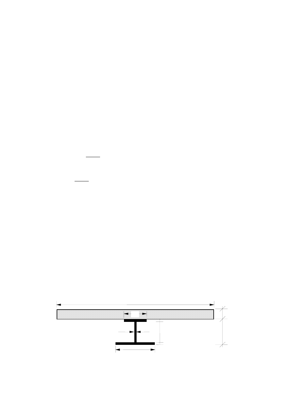
Page 47
Draft prEN1994-1-2:2003
4.3.4.1.4
Combined bending and vertical shear
(1) For partially encased beams the rules of 4.3.4.3.4 should be applied.
NOTE: For unprotected and insulated beams, a method is given in C.2 of Annex C.
4.3.4.1.5
Longitudinal Shear Resistance
(1)P The total design longitudinal shear shall be determined in a manner consistent with the design
bending resistance, taking account of the difference in the normal force in concrete and in structural steel
over a critical length.
(2) In case of design by partial shear connection in the fire situation, the variation of longitudinal shear
forces in function of the heating should be considered.
(3) The total design longitudinal shear over the critical length in the area of sagging bending is calculated
from the compression force in the slab given by:
∑
=
=
m
1
j
c
,
fi
,
M
j
c,
j
,
c,
j
slab
c
f
k
A
F
γ
α
θ
(4.4)
or by the tension force in the steel profile given by:
∑
=
=
n
1
i
a
,
fi
,
M
i,
y
i,
max,
i
a
f
k
A
F
γ
θ
whichever is smaller.
(4.5)
NOTE: For the calculation of the longitudinal shear in the area of hogging bending, a method is given in C.2 of
Annex C.
(4)P Adequate transverse reinforcement shall be provided to distribute the longitudinal shear according to
6.6.6.2 of EN 1994-1-1.
4.3.4.2
Composite beams comprising steel beams with no concrete encasement
4.3.4.2.1
General
(1) The following assessment of the fire resistance of a composite beam comprising a steel beam with no
concrete encasement is applicable to simply supported elements and continuous beams (see Figure 1.2).
4.3.4.2.2
Heating of the cross-section
Steel beam
(1) When calculating the temperature distribution of the steel section, the cross section may be divided
into various parts according to Figure 4.3.
b
1
h
w
b
2
b
eff
e
2
e
1
e
h
h
c
w
Figure 4.3

Page 48
Draft prEN1994-1-2:2003
(2) It is assumed that no heat transfer takes place between these different parts nor between the upper
flange and the concrete slab.
(3) The increase of temperature
t,
a
θ
∆
of the various parts of an unprotected steel beam during the
time interval
∆t may be determined from:
t
h
V
A
c
1
k
net
i
i
a
a
shadow
t.
a
∆
ρ
θ
∆
•
=
[°C]
(4.6)
where
shadow
k
is a correction factor for the shadow effect (see(4))
a
c
is the specific heat of steel in accordance with 3.4.1.2 (1) of EN 1993-1-2
[J/kgK]
a
ρ
is the density of steel in accordance with (1)P of 3.4
[kg/m
3
]
i
A
is the exposed surface area of the part i of the steel cross-section per unit length [m²/m]
i
i
V
A
is the section factor [m-1] of the part i of the steel cross-section
i
V
is the volume of the part i of the steel cross section per unit length
[m
3
/m]
net
h
•
is the design value of the net heat flux per unit area in accordance with 3.1 of EN 1991-1-2
r
,
net
c
,
net
net
h
h
h
•
•
•
+
=
[W/m²]
(
)
t,
a
t
c
c
,
net
h
θ
θ
α
−
=
•
[W/m²]
(
)
(
)
(
)
[
]
4
t,
a
4
t
8
f
m
r
,
net
273
273
10
.
67
,
5
h
+
−
+
=
−
•
θ
θ
ε
ε
[W/m²]
m
ε
as defined in 2.2 (2)
f
ε
is the emissivity of the fire according to 3.1 (6) of EN 1991-1-2
t
θ
is the ambient gas temperature at time t
[°C]
t,
a
θ
is the steel temperature at time t [°C] supposed to be uniform in each part of the steel cross-section
t
∆
is the time interval
[sec]
(4) The shadow effect may be determined from:
[ ]
w
2
1
2
1
w
2
2
1
2
w
1
2
1
shadow
e
e
e
b
2
/
1
b
h
)
b
b
(
4
/
1
h
b
2
/
1
e
e
9
,
0
k
−
+
+
⋅
+
+
−
⋅
+
+
⋅
+
+
⋅
=
(4.7)
with
2
2
,
w
,
w
1
1
b
,
e
h
e
,
b
,
e
and cross sectional dimensions according to Figure 4.3.
NOTE:
The above equation giving the shadow effect (k
shadow
), and its use in (3), is an approximation, based
on the results of a large amount of systematic calculations; for more refined calculation models, the
configuration factor concept as presented in 3.1 and Annex G of EN 1991-1-2 should be applied.

Page 49
Draft prEN1994-1-2:2003
(5) The value of
t
∆
should not be taken as more than 5 seconds for (3).
(6) The increase of temperature
t,
a
θ
∆
of various parts of an insulated steel beam during the time
interval
∆t may be obtained from:
t,
a
θ
∆
=
(
)
−
+
t
t
a,
t
3
1
1
i
V
i
p,
A
a
a
c
p
d
p
∆
θ
θ
ρ
λ
w
-
−
t
10
w
1
e
θ
∆
(4.8)
with
w =
a
a
c
p
p
c
ρ
ρ
i
V
i
p,
A
p
d
and
where:
p
λ
is the thermal conductivity of the fire protection material as specified in (1)P of 3.3.3 [W/mK]
p
d
is the thickness of the fire protection material
[m]
i,
p
A
is the area of the inner surface of the fire protection material per unit length of the
part i of the steel member
[m²/m]
p
c
is the specific heat of the fire protection material as specified in (1)P of 3.3.3
[J/kgK]
p
ρ
is the density of the fire protection material
[kg/m
3
]
t
θ
is the ambient gas temperature at time t
[°C]
t
θ
∆
is the increase of the ambient gas temperature [°C] during the time interval
∆t
(7) Any negative temperature increase
t,
a
θ
∆
obtained by (6) should be replaced by zero.
(8) The value of
t
∆
should not be taken as more than 30 seconds for (6).
(9) For non protected members and members with contour protection, the section factor
i
i
V
A
or
i
i,
p
V
A
should be calculated as follows:
for the lower flange:
i
i
V
A
or
i
i,
p
V
A
=
1
1
1
1
e
b
/
)
e
b
(
2
+
(4.9a)
for the upper flange, when at least 85% of the concrete slab is in contact with the upper flange of the steel
profile or, when any void formed between the upper flange and a profiled steel deck is filled with
non-combustible material:
i
i
V
A
or
i
i,
p
V
A
=
2
2
2
2
e
b
/
)
e
2
b
(
+
(4.9b)
for the upper flange when used with a composite floor when less than 85% of the profiled steel deck is in
contact with the top flange of the steel profile:
i
i
V
A
or
i
i,
p
V
A
=
2
2
2
2
e
b
/
)
e
b
(
2
+
(4.9c)
(10) If the beam depth h does not exceed 500 mm, the temperature of the web may be taken as equal to
that of the lower flange.

Page 50
Draft prEN1994-1-2:2003
(11) For members with box-protection, a uniform temperature may be assumed over the height of the
profile when using (6) together with
V
A
p
.
where:
p
A
is the area of the inner surface of the box protection per unit length of the steel beam
[m²/m]
V
is the volume of the complete cross-section of the steel beam per unit length
[m
3
/m]
(12) As an alternative to (6), temperatures in a steel section after a given time of fire duration may be
obtained from design flow charts determined in conformity with EN 13381 Part 4 and Part 5.
(13) Protection of a steel beam bordered by a concrete floor on top, may be achieved by a horizontal
screen below, and its temperature development may be calculated according to 4.2.5.3 of EN 1993-1-2.
Flat concrete or steel deck-concrete slab system
(14) The following rules (15) to (16) may be used for flat concrete slabs or for steel deck-concrete slab
systems with re-entrant or trapezoidal steel sheets with insulation in the ribs above steel flange of the
beam.
(15) A uniform temperature distribution may be assumed over the effective width
eff
b
of the concrete slab.
NOTE: In order to determine temperatures over the thickness of the concrete slab a method is given in the
Table B.5 of Annex B.
(16) For the mechanical analysis it may be assumed, that for concrete temperatures below 250°C, no
strength reduction of concrete is considered.
4.3.4.2.3
Structural behaviour - critical temperature model
(1) In using the following critical temperature model, the temperature of the steel section is assumed to be
uniform.
(2)P The method is applicable to symmetric sections of a maximum depth h of 500 mm and to a slab
depth
c
h
not less than 120 mm, used in connection with simply supported beams exclusively subject to
sagging bending moments.
(3) The critical temperature
cr
θ
may be determined from the load level
t,
fi
η
applied to the composite
section and from the strength of steel at elevated temperatures
cr
max,
a
f
θ
according to the relationship:
for R30
ay
cr
max,
a
t,
fi
f
f
9
,
0
θ
η
=
(4.10a)
in any other case
ay
cr
max,
a
t,
fi
f
f
0
,
1
θ
η
=
(4.10b)
where
d
t,
d
,
fi
t,
fi
R
E
=
η
and
d
fi
t,
d
,
fi
E
E
η
=
according to (7)P of 4.1 and (3) of 2.4.2.
(4) The temperature rise in the steel section may be determined from (3) or (6) of 4.3.4.2.2 using the
section factor
V
A
m
of the lower flange of the steel section.

Page 51
Draft prEN1994-1-2:2003
4.3.4.2.4
Structural behaviour - bending moment resistance model
(1) As an alternative to 4.3.4.2.3 the bending moment resistance may be calculated by the plastic theory,
taking into account the variation of material properties with temperature (4.3.4.1.2).
(2) The sagging and hogging moment resistances may be calculated taking into account the degree of
shear connection.
NOTE:
For the calculation of sagging and hogging moment resistances, a method is given in Annex C.
4.3.4.2.5
Verification of shear resistance of stud connectors
(1) The design shear resistance in the fire situation of an automatically welded headed stud should be
determined both for solid and steel deck-concrete slab systems in accordance with EN 1994-1-1, except
that the partial safety factor
v
γ
should be replaced by
v
,
fi
,
M
γ
and the smaller of the following reduced
values is to be used:
Rd
,
u
Rd
,
fi
P
.
k
.
8
,
0
P
θ
=
, with
Rd
P
as obtained from equation 6.18 of EN 1994-1-1 or
(4.11a)
Rd
,
c
Rd
,
fi
P
.
k
P
θ
=
, with
Rd
P
as obtained from equation 6.19 of EN 1994-1-1 and
(4.11b)
where values of
θ
,
u
k
and
θ
,
c
k
are taken from Table 3.1 of EN 1993-1-2 and Table 3.1 of EN 1992-1-2
respectively.
(2) The temperature
v
θ
[°C] of the stud connectors and
c
θ
[°C] of the concrete may be taken as 80 % and
40 % respectively of the temperature of the upper flange of the beam.
4.3.4.3
Composite beams comprising steel beams with partial concrete encasement
4.3.4.3.1
General
(1) The bending moment resistance of a partially encased steel beam connected to a concrete slab may
be calculated using 4.3.4.1.2 or alternatively using the method given in this section.
(2) The following assessment of the fire resistance of a composite beam, comprising a steel beam with
partial concrete encasement according to Figure 1.5, is applicable to simply supported or continuous
beams including cantilever parts.
(3) The following rules apply to composite beams heated from below by the standard temperature-time
curve.
(4)P The effect of temperatures on material characteristics is taken into account either by reducing the
dimensions of the parts composing the cross section or by multiplying the characteristic mechanical
properties of materials by a reduction factor.
NOTE:
For the calculation of this reduction factor, a method is given in Annex D
(5)P It is assumed that there is no reduction of the shear resistance of the connectors welded to the
upper flange, as long as these connectors are fixed directly to the active width of that flange.
NOTE:
For the evaluation of this active width, a method is given in D.1 of Annex D
(6) This method allows to classify composite beams in the standard fire classes R30, R60, R90, R120 or
R180.
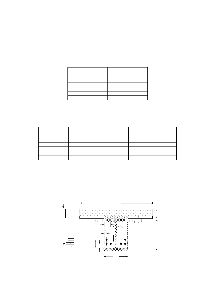
Page 52
Draft prEN1994-1-2:2003
(7) This method may be used in connection with a slab with profiled steel sheets, if for trapezoidal profiles
void fillers are used on top of the beams, if re-entrant profiles are chosen or if (16) of 4.1 is fulfilled.
(8) The slab thickness hc (see Figure 4.4) should be greater than the minimum slab thickness given in
Table 4.9. This table may be used for solid and steel deck-concrete slab systems.
Table 4.9
Standard Fire
Resistance
Minimum Slab Thickness
hc [mm]
R30
60
R60
80
R90
100
R120
120
R180
150
(9) The height h of the profile, bc and the area h bc should be at least equal to the minimum values given
in Table 4.10.
NOTE:
The symbol bc is the minimum value of either the width b of the lower flange or the width of the
concrete part between the flanges, web thickness ew included (see Figure 4.4).
Table 4.10
Standard Fire
Resistance
Minimum Profile Height h and
Minimum Width bc [mm]
Minimum Area h bc [mm²]
R30
120
17500
R60
150
24000
R90
170
35000
R120
200
50000
R180
250
80000
(10) The flange thickness ef should be smaller than the height h of the profile divided by 8.
4.3.4.3.2 Structural
behaviour
(1) For a simply supported beam, the maximum sagging bending moment produced by loads should be
compared to the sagging moment resistance which is calculated according to 4.3.4.3.3.
(2) For the calculation of the sagging moment resistance
+
Rd
,
fi
M
Figure 4.4 may be considered.
h
h
b
b
eff
c
x
_
+
_
+
2
1
3
u
2
u
1,3
u
s3
b
u
s
c
(B)
(A)
NOTE to Figure 4.4:
(A) Example of stress distribution in concrete;
(B) Example of stress distribution in steel
Figure 4.4
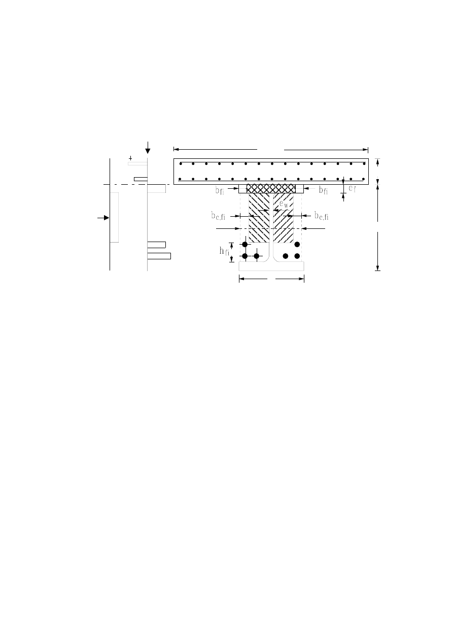
Page 53
Draft prEN1994-1-2:2003
(3)P For a span of a continuous beam, the sagging moment resistance in any critical cross- section and
the hogging moment resistance on each support shall be calculated according to 4.3.4.3.3 and 4.3.4.3.4.
(4) For the calculation of the hogging moment resistance
−
Rd
,
fi
M
Figure 4.5 may be considered.
b
+
_
_
h
h
c
3 · b
_
_
b
c
(A)
(B)
NOTE to Figure 4.5:
(A) Example of stress distribution in concrete;
(B) Example of stress distribution in steel
Figure 4.5
(5) For the calculation of the moment resistance corresponding to the different fire classes, the following
mechanical characteristics may be adopted :
- for the profile, the yield point
ay
f
possibly reduced;
- for the reinforcing bars, the reduced yield point
ry
r
f
k
or
sy
s
f
k
;
- for the concrete, the compressive cylinder strength
c
f
.
(6)P The design values of the mechanical characteristics given in (5) are obtained by applying the partial
material safety factors given in (1)P of 2.3.
(7) Beams, which are considered as simply supported for normal temperature design, may be considered
as continuous in the fire situation if (5) of 5.4.1 is fulfilled.
4.3.4.3.3
Sagging moment resistance Mfi,Rd+
(1) The width
eff
b
of the concrete slab should be equal to the effective width chosen according to 5.4.1.2
of EN 1994-1-1.
(2) In order to calculate the sagging moment resistance, the concrete of the slab in compression, the
upper flange of the profile, the web of the profile, the lower flange of the profile and the reinforcing bars
should be considered. For each of these parts of the cross section a corresponding rule, may define the effect
of the temperature. The concrete in tension of the slab and the concrete between the flanges of the
profile should be ignored (see Figure 4.4).
(3) On the basis of the essential equilibrium conditions and on the basis of the plastic theory, the neutral
bending axis may be defined and the sagging moment resistance may be calculated.

Page 54
Draft prEN1994-1-2:2003
4.3.4.3.4
Hogging moment resistance Mfi,Rd -
(1) The effective width of the concrete slab is reduced to three times the width of the steel profile (see
Figure 4.5). This effective width determines the reinforcing bars to be taken into account.
(2) In order to calculate the hogging moment resistance, the reinforcing bars in the concrete slab, the
upper flange of the profile except when (4) is applicable, and the concrete in compression between the
flanges of the profile should be considered. For each of these parts of the cross-section a corresponding
rule may define the effect of the temperature. The concrete in tension of the slab, the web and the lower
flange of the profile should be ignored.
NOTE:
For the design of the web, a method is given in D.2 of Annex D
(3) The reinforcing bars situated between the flanges may participate in compression and be considered
in the calculation of the hogging moment resistance, provided the corresponding stirrups fulfil the relevant
requirements given in EN 1992-1-1, in order to restrain the reinforcing bars against local buckling, and
provided either the steel profile and the reinforcing bars are continuous at the support or (5) of 5.4.1 is
applicable.
(4) In the case of a simply supported beam according to (5) of 5.4.1, the upper flange should not be taken
into account if it is in tension.
(5) On the basis of the essential equilibrium conditions and on the basis of the plastic theory, the neutral
bending axis may be defined and the hogging moment resistance may be calculated.
(6)P The principles of plastic global analysis apply for the combination of sagging and hogging moments
if plastic hinges develop at supports.
(7) Composite beams comprising steel beams with partial concrete encasement, may be assumed not to
fail through lateral torsional buckling in the fire situation.
4.3.4.4
Steel beams with partial concrete encasement
(1) If the partially encased beam supports a concrete slab, without shear connection according to
Figure 1.3, the rules given in 4.3.4.3 may be applied by assuming no mechanical resistance of the
reinforced concrete slab.
4.3.5
Composite columns
4.3.5.1 Structural behaviour
(1)P The simple calculation models described hereafter shall only be used for columns in braced frames.
(2)P In simple calculation models the design value in the fire situation, of the resistance of composite
columns in axial compression (buckling load) shall be obtained from:
Rd
,
pl
,
fi
Rd
,
fi
N
N
χ
=
(4.12)
where:
χ
is the reduction coefficient for buckling curve c of 6.3.1 of EN 1993-1-1 and depending on the
non-dimensional slenderness ratio
θ
λ
,
Rd
,
pl
,
fi
N
is the design value of the plastic resistance to axial compression in the fire situation.
.

Page 55
Draft prEN1994-1-2:2003
(3) The cross section of a composite column may be divided into various parts concerning the steel
profile "a", the reinforcing bars "s" and the concrete "c".
(4) The design value of the plastic resistance to axial compression in the fire situation is given by:
(
)
(
)
(
)
∑
∑
∑
+
+
=
m
k
j
c
fi,
M,
c,
c,
s
fi,
M,
smax,
s,
a
fi,
M,
amax,
a,
Rd
,
pl
,
fi
f
A
f
A
A
N
f
γ
γ
γ
θ
θ
θ
θ
θ
θ
(4.13)
where:
θ
i,
A
is the area of each element of the cross-section.
(5) The effective flexural stiffness is calculated as
( )
∑
∑
∑
+
+
=
m
,
c
sec,
,
c
,
c
k
,
s
,
s
,
s
j
,
a
,
a
,
a
eff
,
fi
I
E
I
E
I
E
EI
θ
θ
θ
θ
θ
θ
θ
θ
θ
ϕ
ϕ
ϕ
(4.14)
where:
θ
,
i
I
is the second moment of area, of the partially reduced part i of the cross-section for bending
around the weak or strong axis,
θ
ϕ
,
i
is the reduction coefficient depending on the effect of thermal stresses.
θ
sec,
,
c
E
is the characteristic value for the secant modulus of concrete in the fire situation, given by
θ,
c
f
divided by
θ
ε
,
cu
(see Figure 3.1 of EN 1992-1-2).
NOTE:
A method is given in E.6 of Annex E, for the evaluation of the reduction coefficient
(6) The Euler buckling load or elastic critical load in the fire situation is as follows
2
eff
,
fi
cr
,
fi
/
)
EI
(
²
N
θ
π
l
=
(4.15)
where:
θ
l
is the buckling length of the column in the fire situation.
(7) The non-dimensional slenderness ratio is given by:
cr
,
fi
R
,
pl
,
fi
N
N
=
θ
λ
(4.16)
where
R
,
pl
,
fi
N
is the value of
Rd
,
pl
,
fi
N
according to (4) when the factors
a
,
fi
,
M
γ
,
s
,
fi
,
M
γ
and
c
,
fi
,
M
γ
are taken as
1,0.
(8) For the determination of the buckling length
θ
l
of columns, the rules of EN 1994-1-1 apply, with the
exception given hereafter.
(9) A column at the level under consideration, fully connected to the column above and below, may be
considered as completely built-in at such connections, provided the resistance to fire of the building
elements, which separate the levels under consideration, is at least equal to the fire resistance of the
column.
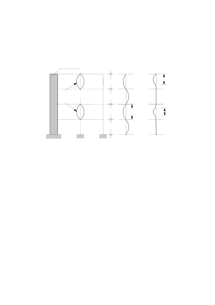
Page 56
Draft prEN1994-1-2:2003
(10) In the case of a steel frame, for which each of the stories may be considered as a fire compartment
with sufficient fire resistance, (9) means, that the buckling length of a column on an intermediate storey
subject to fire,
θ
l
equals 0,5 times the system length L. For a column on the top floor the buckling length
in the fire situation,
θ
l
equals 0,7 times the system length L, (see Figure 4.6).
column
fire exposed
(a)
(b)
(c)
rigid core
θ
l
L
L
L
L
θ
l
θ
l
l
a) section through the building
b) deformation mode at room temperature
c) deformation mode at elevated temperature
Figure 4.6: Structural behaviour of columns in braced frames
(11) The following rules apply for composite columns heated all around by the standard temperature-time
curve.
4.3.5.2 Steel sections with partial concrete encasement
(1) The fire resistance of columns composed of steel sections with partial concrete encasement
according to Figure 1.7 may be assessed by simple calculation models valid at least for buckling and
bending around the weak axis of the steel profile.
(2) These calculation models may only be applied in the following conditions:
buckling length
θ
l
≤
13,5b
230 mm
≤
height of cross section h
≤
1100 mm
230 mm
≤
width of cross section b
≤
500 mm
1 %
≤
percentage of reinforcing steel
≤
6 %
standard fire resistance
≤
120 min
(3) In addition to (2), the minimum cross-section size b and h should be limited to 300 mm for the fire
classes R90 and R120.

Page 57
Draft prEN1994-1-2:2003
(4) For the calculation model of (1), (2) and (3), the maximum buckling length
θ
l
should be limited to 10b
in the following situations:
- for R60, if 230 mm
≤ b < 300 mm or if h/b > 3 and
- for R90 and R120, if h/b > 3.
NOTE 1: For steel sections with partial concrete encasement, a method is given in Annex E
NOTE 2: For eccentric loads a method is given in E.7 of Annex E
(5) For constructional details refer to 5.1, 5.3.1 and 5.4.
4.3.5.3 Unprotected concrete filled hollow sections
(1) The fire resistance of columns composed of unprotected concrete filled square or circular hollow
sections may be assessed by simple calculation models.
(2) These calculation models may only be applied for square or circular sections in the following
conditions:
buckling length
θ
l
≤ 4,5 m
140 mm
≤
depth b or diameter d of cross-section
≤ 400 mm
C20/25
≤ concrete
grades
≤ C40/50
1 %
≤
percentage of reinforcing steel
≤ 5 %
Standard fire resistance
≤ 120 min.
NOTE 1: For unprotected concrete filled hollow sections, a method is given in Annex F
NOTE 2: For eccentric loads a method is given in F.4 of Annex F
(3) For constructional details refer to 5.1, 5.3.2 and 5.4.
4.3.5.4 Protected concrete filled hollow sections
(1) An improvement of the fire resistance of concrete filled hollow sections may be obtained by using a
protection system around the steel column in order to decrease the heat transfer.
(2) The performance of the protection system used for concrete filled hollow sections should be assessed
according to:
- EN 13381-2 as far as vertical screens are concerned and
- EN 13381-6 as far as coating or sprayed materials are concerned.
(3) The load bearing criterion "R" may be considered fulfilled as long as the temperature of the hollow
section is lower than 350°C.

Page 58
Draft prEN1994-1-2:2003
4.4
Advanced calculation models
4.4.1
Basis of analysis
(1)P Advanced calculation models shall provide a realistic analysis of structures exposed to fire. They
shall be based on fundamental physical behaviour in such a way as to lead to a reliable approximation of
the expected behaviour of the relevant structural component under fire conditions.
NOTE:
Compared with tabulated data and simple calculation models, advanced calculation models give an
improved approximation of the actual structural behaviour under fire conditions.
(2) Advanced calculation models may be used for individual members, for subassemblies or for entire
structures.
(3) Advanced calculation models may be used with any type of cross-section.
(4) Advanced calculation models may include separate calculation models for the determination of
- the development and distribution of the temperature within structural elements (thermal response
model) and
- the mechanical behaviour of the structure or of any part of it (mechanical response model).
(5)P Any potential failure modes not covered by the advanced calculation model (including local buckling,
insufficient rotation capacity, spalling and failure in shear), shall be eliminated by appropriate means
which may be constructional detailing.
(6)P Advanced calculation models shall be used when information concerning stress and strain evolution,
deformations and / or temperature fields are required.
(7) Advanced calculation models may be used in association with any time-temperature heating curve,
provided that the material properties are known for the relevant temperature range.
4.4.2
Thermal response
(1)P Advanced calculation models for thermal response shall be based on the acknowledged principles
and assumptions of the theory of heat transfer.
(2)P The thermal response model shall consider
- the relevant thermal actions specified in EN 1991-1-2 and
- the variation of the thermal properties of the materials according to 3.1 and 3.3.
(3) The effects of non-uniform thermal exposure and of heat transfer to adjacent building components
may be included where appropriate.
(4) The influence of any moisture content and of any migration of the moisture within the concrete and the
fire protection material, may conservatively be neglected.

Page 59
Draft prEN1994-1-2:2003
4.4.3
Mechanical response
(1)P Advanced calculation models for mechanical response shall be based on the acknowledged
principles and assumptions of the theory of structural mechanics, taking into account the effects of
temperature.
(2)P The mechanical response model shall also take account of:
- the combined effects of mechanical actions, geometrical imperfections and thermal actions;
- the temperature dependent mechanical properties of the materials;
- geometrical non linear effects and
- the effects of non-linear material properties, including the effects of unloading on the structural
stiffness.
(3)P The effects of thermally induced strains and stresses, both due to temperature rise and due to
temperature differentials, shall be considered.
(4) Provided that the stress-strain relationships given in 3.1 and 3.2 are used, the effect of high
temperature creep need not be given explicit consideration.
(5)P The deformations at ultimate limit state, given by the calculation model, shall be limited as necessary
to ensure that compatibility is maintained between all parts of the structure.
4.4.4
Validation of advanced calculation models
(1)P The validity of any advanced calculation model shall be verified by applying the following rules (2)P
and (4)P.
(2)P A verification of the calculation results shall be made on basis of relevant test results.
(3) Calculation results may refer to deformations, temperatures and fire resistance times.
(4)P The critical parameters shall be checked, by means of a sensitivity analysis, to ensure that the
model complies with sound engineering principles.
(5) Critical parameters may refer to the buckling length, the size of the elements, the load level, etc.
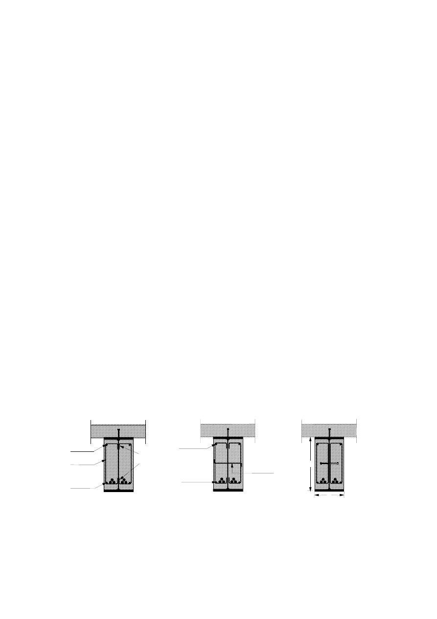
Page 60
Draft prEN1994-1-2:2003
Section 5
Constructional details
5.1
Introduction
(1)P Constructional detailing shall guarantee the required level of shear connection between steel and
concrete for composite columns and composite beams, for normal temperature design and in the fire
situation.
(2)P If this shear connection cannot be maintained under fire conditions, either the steel or the concrete
part of the composite section shall fulfil the fire requirements independently.
(3) For concrete-filled hollow sections and partially encased sections, shear connectors should not be
attached to the directly heated unprotected parts of the steel sections. However thick bearing blocks with
shear studs are accepted (see Figures 5.5 and 5.6).
(4) If welded sections are used, the steel parts directly exposed to fire should be attached to the protected
steel parts by welds sufficiently strong.
(5) For fire exposed concrete surfaces, the concrete cover of reinforcing bars defined in 4.4.1 of
EN 1992-1-1, should be at least 20 mm for all reinforcements, but not exceeding 50 mm. This
requirement is needed in order to reduce the danger of spalling under fire exposure.
(6) In cases where concrete encasement provides only an insulation function, steel fabric reinforcement
with a maximum spacing of 250 mm and a minimum diameter of 4 mm in both directions is to be placed
around the section and should fulfil (5).
(7) When the concrete cover of reinforcing bars exceeds 50 mm, an additional mesh has to be foreseen
near the exposed surface to satisfy (5).
5.2
Composite beams
(1)P For composite beams comprising steel beams with partial concrete encasement, the concrete
between the flanges shall be reinforced and fixed to the web of the beam.
(2) The partially encased concrete should be reinforced by stirrups of a minimum diameter
∅s of 6 mm or
by a reinforcing fabric with a minimum diameter of 4 mm. The concrete cover of the stirrups should not
exceed 35 mm. The distance between the stirrups should not exceed 250 mm. In the corners of the
stirrups a longitudinal reinforcement of a minimum diameter
∅r of 8 mm should be placed (
see Figure 5.1
).
r
s
φ
r
welding
a
w
φ
s
0,5
l
w
φ
s
4
φ
r
≥ 8 mm
φ
r
8 mm
φ
b
6 mm
b
studs
h
0,3 b
h
v
φ
φ
≥ 8 mm
≥ 6 mm
≥
≥
8 mm
≥
≥
≥
≥
≥
10 mm
d
a) Welding of stirrups
b) Bars through holes in the
c) Welding of studs
to the web
web, fixed to the stirrups
to the web
Figure 5.1: Measures providing connection between the steel profile and the encasing concrete
(3) The concrete between the flanges may be fixed to the web by welding the stirrups to the web by
a fillet weld with a minimum throat thickness aw of 0,5 ∅s and a minimum length lw of 4 ∅s
(see Figure 5.1.a).
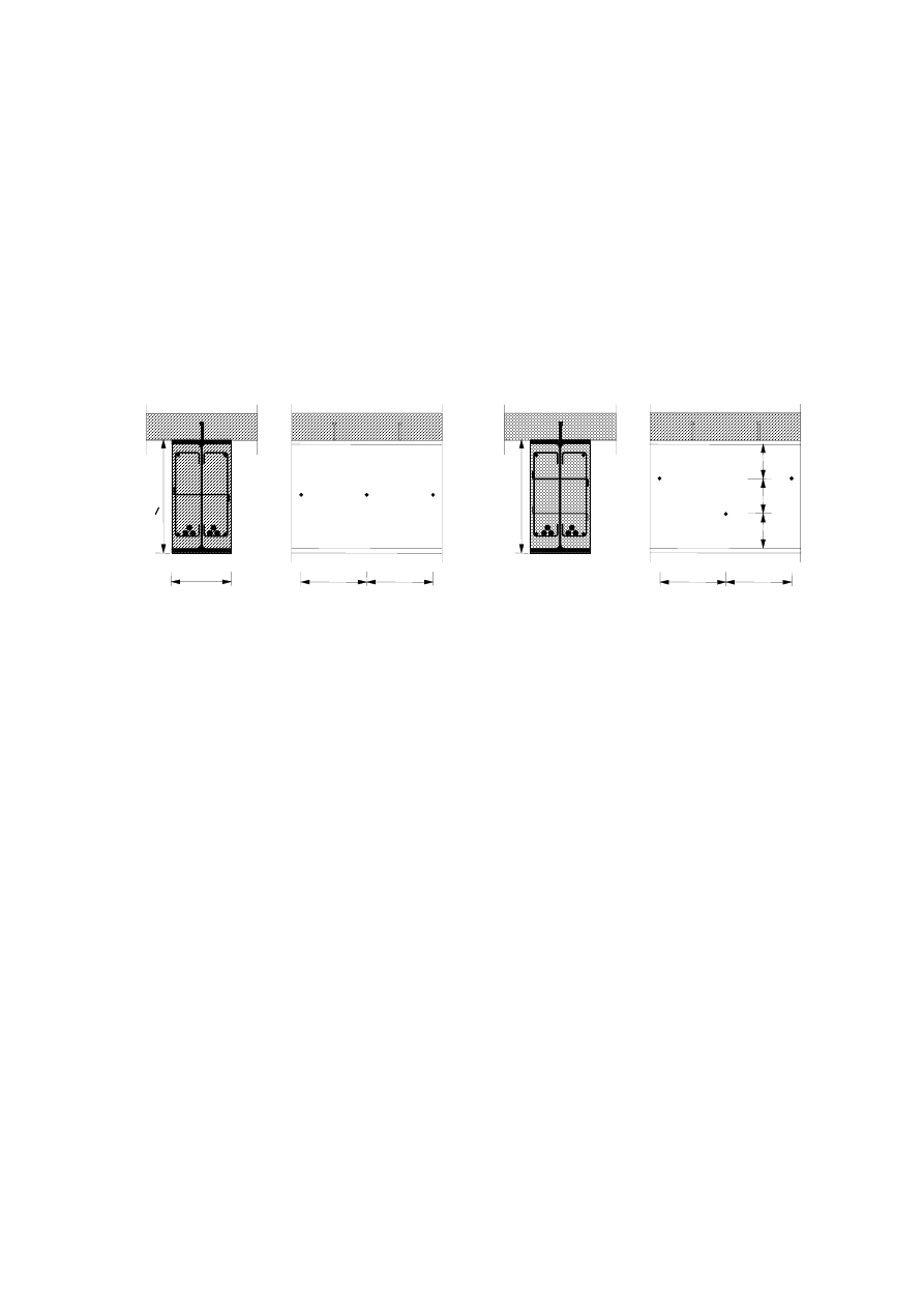
Page 61
Draft prEN1994-1-2:2003
(4) The concrete between the flanges may be fixed to the web of the beam by means of bars, penetrating
the web through holes, or studs welded to both sides of the web under following conditions:
- the bars have a minimum diameter
∅b of 6 mm (see Figures 5.1.b) and
- the studs have a minimum diameter d of 10 mm and a minimum length hv of 0,3b. Their head should
be covered by at least 20 mm of concrete (see Figures 5.1.c);
- the bars or studs are arranged as given in Figure 5.2.a for steel profiles with a maximum depth h of
400 mm or as given in Figure 5.2.b for steel profiles with a depth h larger than 400 mm. When the
height is larger than 400 mm, the rows of connectors disposed in staggered way should be at a
distance smaller or equal to 200 mm.
≤ 400
b
h >
400
≤ 400
≤ 400
≤ 400
≤ 200
≤ 200
≤ 200
h < 40
0
a) height of steel profile h
≤ 400 mm
b) height of steel profile h > 400 mm
Figure 5.2: Arrangement of bars or studs providing connection between the steel profile and the
encased concrete
5.3
Composite columns
5.3.1
Composite columns with partially encased steel sections
(1)P The concrete between the flanges of the steel sections shall be fixed to the web either by means of
stirrups or by studs (see Figure 5.1).
(2) The stirrups should be welded to the web or penetrate the web through holes. If studs are used, they
should be welded to the web.
(3) The spacing of studs or stirrups along the column axis should not exceed 500 mm. At load
introduction areas this spacing should be reduced according to EN 1994-1-1.
NOTE : For steel sections with a profile depth h greater than 400 mm, studs and stirrups may be chosen
according to Figure E.2 of Annex E.
5.3.2
Composite columns with concrete filled hollow sections
(1)P There shall be no additional shear connection along the column, between the beam to column
connections.
(2) The additional reinforcement should be held in place by means of stirrups and spacers.
(3) The spacing of stirrups along the column axis should not exceed 15 times the smallest diameter of the
longitudinal reinforcing bars.
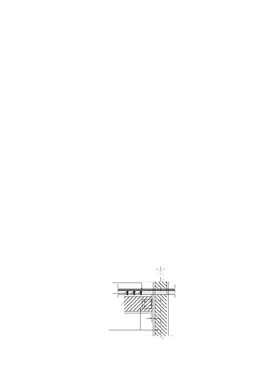
Page 62
Draft prEN1994-1-2:2003
(4)P The hollow steel section shall contain holes with a diameter of not less than 20 mm located at least
one at the top and one at the bottom of the column in every storey.
(5) The spacing of these holes should never exceed 5 m.
5.4
Connections between composite beams and columns
5.4.1
General
(1)P The beam to column connections shall be designed and constructed in such a way that they support
the applied forces and moments for the same fire resistance time as that of the member transmitting the
actions.
(2) For fire protected members one way of achieving the requirement of (1)P is to apply at least the same
fire protection as that of the member transmitting the actions, and to ensure for the connection a load
ratio which is less than or equal to that of the beam.
NOTE:
For the design of fire protected connections, methods are given in 4.2.1 (6) and Annex D of
EN 1993-1-2.
(3) Composite beams and columns may be connected using bearing blocks or shear flats welded to the
steel section of the composite column. The beams are supported on the bearing blocks or their webs are
bolted to the shear flats. If bearing blocks are used, appropriate constructional detailing should guarantee
that the beam cannot slip from supports during the cooling phase.
(4) If connections are performed in accordance with Figures 5.4 to 5.6, their fire resistance complies with
the requirements of the adjacent structural members. Bearing blocks welded to composite columns may
be used with protected steel beams.
(5) In the case of a beam simply supported for normal temperature design, a hogging moment may be
developed at the support in the fire situation, provided the concrete slab is reinforced in such a way as to
guarantee the continuity of the slab and provided there is an effective transmission of the compression
force through the steel connection (see Figure 5.3).
(6) A hogging moment may always be developed according to (5) and Figure 5.3 in the fire situation if
- gap < 10 mm or
- 10
mm
≤ gap < 15 mm, for R30 up to R180 and a beam span larger that 5 m.
gap
Continuous
reinforcing bar
Sections with
infilled concrete
studs
Figure 5.3
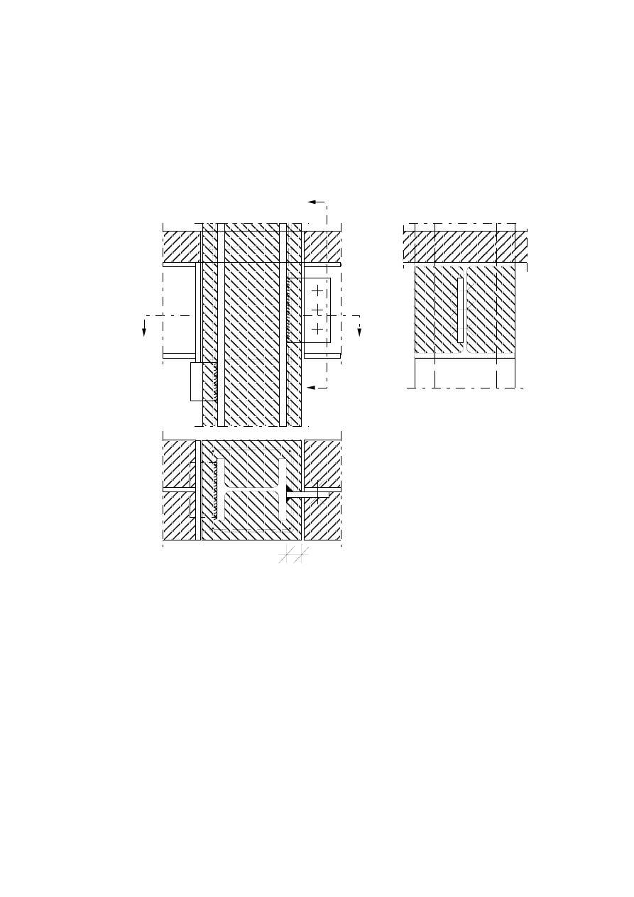
Page 63
Draft prEN1994-1-2:2003
5.4.2
Connections between composite beams and composite columns with steel sections
encased in concrete
(1) Bearing blocks or shear flats according to Figure 5.4 may be directly welded to the flange of the steel
profile of the composite column in order to support a composite beam.
A
A
B
B
c
B - B
A - A
Figure 5.4: Examples of connections to a totally encased steel section of a column.
5.4.3
Connections between composite beams and composite columns with partially encased
steel sections.
(1) Additional studs should be provided if unprotected bearing blocks are used (Figure 5.5.a), because
welds are exposed to fire. The shear resistance of studs should be checked according to 4.3.4.2.5 (1)
with a stud temperature equal to the average temperature of the bearing block.
(2) For fire resistance classes up to R 120 the additional studs are not needed if the following conditions
are fulfilled (see Figure 5.5.b):
- the unprotected bearing block has a minimum thickness of at least 80 mm;
- it is continuously welded on four sides to the column flange;
- the upper weld, protected against direct radiation, has a thickness of at least 1,5 times the thickness of
the surrounding welds and should in normal temperature design support at least 40 % of the design shear
load.
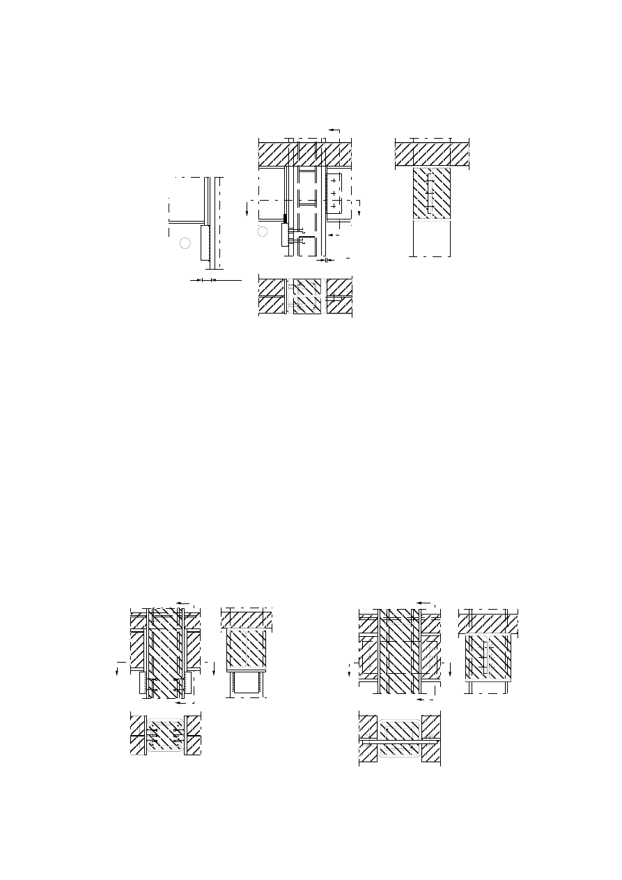
Page 64
Draft prEN1994-1-2:2003
A - A
B - B
B
B
A
A
80 mm
gap < 10 mm
b
a
Figure 5.5: Examples of connections to a partially encased steel section
(3) If shear flats are used, the remaining gap between beam and column needs no additional protection if
smaller than 10 mm (see Figure 5.5.a).
(4) For different types of connections, refer to (1)P of 5.4.1.
5.4.4
Connections between composite beams and composite columns with concrete filled
hollow sections
(1) Composite beams may be connected to composite columns with concrete filled hollow sections using
either bearing blocks or shear flats (Figure 5.6).
(2)P Shear and tension forces shall be transmitted by adequate means from the beam to the reinforced
concrete core of this composite column type.
(3) If bearing blocks are used (Figure 5.6.a) the shear load transfer in case of fire should be ensured by
means of additional studs. The shear resistance of studs should be checked according to 4.3.4.2.5(1)
with a stud temperature equal to the average temperature of the bearing block.
(4) If shear flats are used (Figure 5.6.b), they should penetrate the column and they should be connected
to both walls by welding.
A
B - B
B
B
A - A
A
B
B
A
B - B
A - A
A
a) Bearing blocks with additional studs
b) Penetrating shear flats
Figure 5.6: Examples of connections to a concrete filled hollow section

Page 65
Draft prEN1994-1-2:2003
Annex A
[informative]
Concrete stress-strain relationships adapted to natural fires
with a decreasing heating branch for use
in advanced calculation models.
(1) Concrete, which is cooling down to ambient temperature of 20°C after having reached a maximum
temperature of
max
θ
, is not recovering its initial compressive strength
c
f
.
(2) When considering the descending branch of the concrete heating curve (see Figure A.1), the value of
θ
ε
,
cu
and the value of the slope of the descending branch of the stress-strain relationship may both be
maintained equal to the corresponding values for
max
θ
(see Figure A.2).
(3) The residual compressive strength of concrete heated to a maximum temperature
max
θ
and having
cooled down to the ambient temperature of 20°C, may be given as follows:
c
C
20
,
,
c
f
f
ϕ
θ
=
°
where for
C
100
C
20
max
°
°
<
≤
θ
;
max
,
c
k
θ
ϕ
=
C
300
C
100
max
°
°
<
≤
θ
;
(
)
[
]
200
100
185
,
0
95
,
0
max
−
−
=
θ
ϕ
C
300
max
°
≥
θ
;
max
,
c
k
9
,
0
θ
ϕ
=
Note:
The reduction factor
max
,
c
k
θ
is taken according to table 3.1 of EN 1992-1-2
(4) During the cooling down of concrete with
C
20
max
°
≥
≥
θ
θ
, the corresponding compressive cylinder
strength
θ
,
c
f
may be interpolated in a linear way between
max
,
c
f
θ
and
C
20
,
,
c
f
°
θ
.
(5) The previous rules may be illustrated in Figure A.2 for a concrete grade C40/50 as follows:
1
θ
= 200°C;
1
,
c
f
θ
= 0,95 . 40 = 38
[N/mm²]
1
,
cu
θ
ε
= 0,55
[%]
1
,
ce
θ
ε
= 2,5
[%]
2
θ
= 400°C;
2
,
c
f
θ
= 0,75 . 40 = 30
[N/mm²]
2
,
cu
θ
ε
= 1
[%]
2
,
ce
θ
ε
= 3,0
[%]
For a possible maximum concrete temperature of
max
θ
= 600°C:
max
,
c
f
θ
= 0,45 . 40 = 18
[N/mm²]
max
,
cu
θ
ε
= 2,5
[%]
max
,
ce
θ
ε
= 3,5
[%]
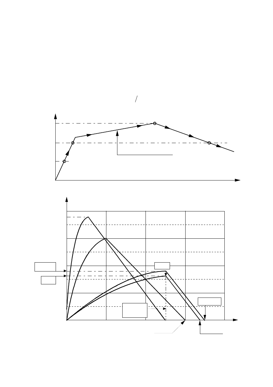
Page 66
Draft prEN1994-1-2:2003
For any lower temperature obtained during the subsequent cooling down phase as for
3
θ
= 400°C:
(
)
2
,
16
40
.
45
,
0
.
9
,
0
f
k
9
,
0
f
c
max
,
c
C
20
,
,
c
=
=
=
°
θ
θ
[N/mm²]
(
)
(
) (
)
[
]
4
,
17
20
/
f
f
f
f
max
3
max
C
20
,
,
c
max
,
c
max
,
c
3
,
c
=
−
−
−
−
=
°
θ
θ
θ
θ
θ
θ
θ
[N/mm²]
5
,
2
max
,
cu
3
,
cu
=
=
θ
θ
ε
ε
[%]
(
)
[
]
46
,
3
f
f
max
,
c
3
,
c
max
,
cu
max
,
ce
3
,
cu
3
,
ce
=
−
+
=
θ
θ
θ
θ
θ
θ
ε
ε
ε
ε
[%]
200°C
400°C
600°C
= Maximum temperature
obtained in concrete
Concrete heating curve
t [min]
2
θ
1
θ
3
θ
c
θ
max
θ
[°C]
Figure A.1
0
1
2
3
4
0
10
20
30
40
θ
max
θ
1
θ
2
θ
3
ε
ce,
θ
max
ε
ce,
θ
3
ε
ce,
θ
2
ε
c,
θ[%]
σ
c,
θ [N/mm²]
f
c,
θ
1
f
c,
θ
3
f
c,
θ
max
ε
cu,
θ
max
ε
cu,
θ
3
=
Figure A.2
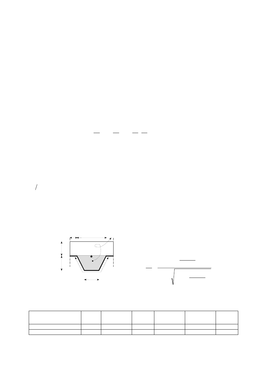
Page 67
Draft prEN1994-1-2:2003
Annex B
[informative]
Model for the calculation of the fire resistance of unprotected
composite slabs exposed to fire beneath the slab according to
the standard temperature-time curve
B.1 Fire resistance according to thermal insulation
(1) The decisive fire resistance with respect to both the average temperature rise (=140°C) and the
maximum temperature rise (=180°C), criterion “I”, follows from the following equation :
3
r
5
3
4
r
3
2
1
1
0
i
1
L
A
a
1
a
L
A
a
a
h
a
a
t
l
l
⋅
⋅
+
⋅
+
⋅
+
⋅
+
⋅
+
=
Φ
(B.1)
where:
i
t
the fire resistance with respect to thermal insulation
[min]
A
concrete volume of the rib per m rib length
[mm
3
/m]
r
L
exposed area of the rib per m rib length
[mm
2
/m]
r
L
A
the rib geometry factor
[mm]
Φ
the view factor of the upper flange
[-]
3
l
the width of the upper flange (see Figure B.1)
[mm].
For the factors
i
a
, for different values of the concrete depth
1
h
, for both normal and light weight
concrete, refer to Table B.1. For intermediate values, linear interpolation is allowed.
exposed surface: L
r
area: A
l
1
l
2
h
2
h
1
½
l
3
2
2
1
2
2
2
2
1
2
r
2
h
2
2
.
h
L
A
−
+
+
+
=
l
l
l
l
l
(B.2)
Figure B.1 : Definition of the rib geometry factor A/L
r
for ribs of composite slabs.
Table B.1 :
Coefficients for determination of the fire resistance with respect to thermal
insulation
a
0
[min]
a
1
[min/mm]
a
2
[min]
a
3
[min/mm]
a
4
[mm min]
a
5
[min]
Normal weight concrete
-28,8
1,55
-12,6
0,33
-735
48,0
Light weight concrete
-79,2
2,18
-2,44
0,56
-542
52,3

Page 68
Draft prEN1994-1-2:2003
(2) The configuration or view factor
Φ
of the upper flange may be determined as follows:
3
2
2
1
2
2
2
2
1
3
2
2
l
2
l
l
h
2
l
l
l
h
−
+
−
−
+
+
=
Φ
[-]
(B.3)
B.2 Calculation of the sagging moment resistance M
fi,Rd
+
(1) The temperatures
a
θ
of the lower flange, web and upper flange of the steel decking may be given by:
2
4
3
r
2
3
1
0
a
b
b
L
A
b
1
b
b
Φ
Φ
θ
⋅
+
⋅
+
⋅
+
⋅
+
=
l
(B.4)
where:
a
θ
is the temperature of the lower flange, web or upper flange
[°C]
For factors
i
b
, for both normal and light weight concrete, refer to Table B.2. For intermediate values,
linear interpolation is allowed.
Table B.2: Coefficients for the determination of the temperatures of the parts of the steel decking
Concrete
Fire resistance
[min]
Part of the
steel sheet
b
0
[
o
C]
b
1
[
o
C]. mm
b
2
[
o
C]. mm
b
3
[
o
C]
b
4
[
o
C]
60
Lower flange
Web
Upper flange
951
661
340
-1197
-833
-3269
-2,32
-2,96
-2,62
86,4
537,7
1148,4
-150,7
-351,9
-679,8
90
Lower flange
Web
Upper flange
1018
816
618
-839
-959
-2786
-1,55
-2,21
-1,79
65,1
464,9
767,9
-108,1
-340,2
-472,0
Normal
weight
concrete
120
Lower flange
Web
Upper flange
1063
925
770
-679
-949
-2460
-1,13
-1,82
-1,67
46,7
344,2
592,6
-82,8
-267,4
-379,0
30
Lower flange
Web
Upper flange
800
483
331
-1326
-286
-2284
-2,65
-2,26
-1,54
114,5
439,6
488,8
-181,2
-244,0
-131,7
60
Lower flange
Web
Upper flange
955
761
607
-622
-558
-2261
-1,32
-1,67
-1,02
47,7
426,5
664,5
-81,1
-303,0
-410,0
90
Lower flange
Web
Upper flange
1019
906
789
-478
-654
-1847
-0,91
-1,36
-0,99
32,7
287,8
469,5
-60,8
-230,3
-313,0
Light
weight
concrete
120
Lower flange
Web
Upper flange
1062
989
903
-399
-629
-1561
-0,65
-1,07
-0,92
19,8
186,1
305,2
-43,7
-152,6
-197,2
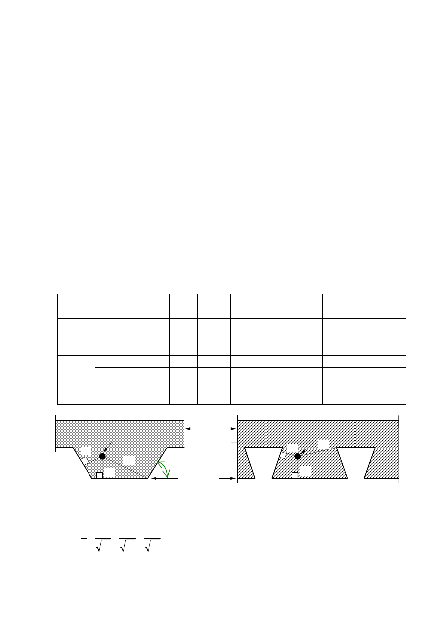
Page 69
Draft prEN1994-1-2:2003
(2) The view factor
Φ
of the upper flange and the rib geometry factor A/L
r
may be established according
to B.1.
(3) The temperature
s
θ
of the reinforcement bars in the rib (see Figure B.2) is given by:
(
)
(
)
⋅
+
⋅
+
⋅
+
⋅
+
⋅
+
=
3
5
4
r
3
2
2
3
1
0
s
1
c
c
L
A
c
z
c
h
u
c
c
l
α
θ
(B.5)
where:
s
θ
the temperature of additional reinforcement in the rib
[°C]
3
u
distance to lower flange
[mm]
z
indication of the position in the rib (see (4))
[mm
-0.5
]
α
angle of the web
[degrees]
For factors
i
c
for both normal and light weight concrete, refer to Table B.3. For intermediate values, linear
interpolation is allowed.
Table B.3:
Coefficients for the determination of the temperatures of the reinforcement
bars in the rib.
Concrete
Fire resistance [min]
c
0
[
o
C]
c
1
[
o
C]
c
2
[
o
C]. mm
0.5
c
3
[
o
C].mm
c
4
[
o
C/
o
]
c
5
[
o
C].mm
60
1191
-250
-240
-5,01
1,04
-925
90
1342
-256
-235
-5,30
1,39
-1267
Normal
weight
concrete
120
1387
-238
-227
-4,79
1,68
-1326
30
809
-135
-243
-0,70
0,48
-315
60
1336
-242
-292
-6,11
1,63
-900
90
1381
-240
-269
-5,46
2,24
-918
Light
weight
concrete
120
1397
-230
-253
-4,44
2,47
-906
Slab
Steel Sheet
Reinforcing
bar
u
2
u
1
u
3
u
2
u
1
u
3
α
Figure B.2
(4) The z-factor which indicates the position of the reinforcement bar is given by:
3
2
1
u
1
u
1
u
1
z
1
+
+
=
(B.6)
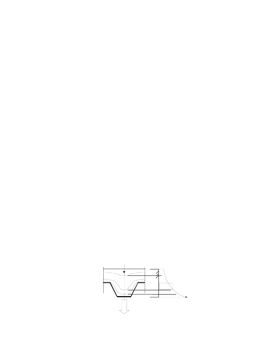
Page 70
Draft prEN1994-1-2:2003
(5) The distances
1
u
,
2
u
and
3
u
are expressed in mm and are defined as follows:
1
u
,
2
u
: shortest distance of the centre of the reinforcement bar to any point of the webs of the steel
sheet;
3
u
:
distance of the centre of the reinforcement bar to the lower flange of the steel sheet.
(6) Based on the temperatures given by (1) to (5), the ultimate stresses of the parts of the composite slab
and the sagging moment resistance are calculated according to 4.3.1.
B.3 Calculation of the hogging moment resistance M
fi,Rd
-
:
(1) As a conservative approximation, the contribution of the steel decking to the hogging moment capacity
may be ignored.
(2) The hogging moment resistance of the slab is calculated by considering a reduced cross section. The
parts of the cross section, with temperatures beyond a certain limiting temperature
lim
θ
, are neglected.
The remaining cross section is considered as under room temperature conditions.
(3) The remaining cross section is established, on the basis of the isotherm for the limiting temperature
(see Figures B.3). The isotherm for the limiting temperature, is schematised by means of 4 characteristic
points, as follows:
point I: is situated at the central line of the rib, at a distance from the lower flange of the steel sheet and
calculated in function of the limiting temperature according to equation B.7 and B.9 of (4) and
(5);
point IV: is situated at the central line between two ribs, at distance from the upper flange of the steel
sheet, calculated in function of the limiting temperature according to equations B.7 and B.14 of
(4) and (5);
point II: is situated on a line through point I, parallel to the lower flange of the steel sheet, at a distance
from the web of the steel sheet, equal to that from the lower flange;
point III: is situated on a line through the upper flange of the steel sheet, at a distance from the web of
the steel sheet, equal to the distance of point IV to the upper flange.
The isotherm is obtained by linear interpolation between the points I, II, III and IV.
Note:
The limiting temperature is derived from equilibrium over the cross section and therefore has no
relation with temperature penetration
Figure B.3.a : Schematisation isotherm
Temperature
A) Temperature distribution in a cross section
Isotherm for θ θ
=
2
Isotherm for θ θ
=
lim
Isotherm for θ θ
=
1
θ
2
θ
lim
θ
1
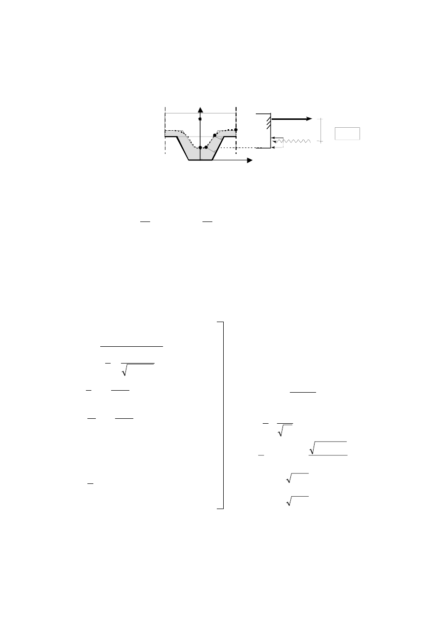
Page 71
Draft prEN1994-1-2:2003
Figure B.3.b: Establishment of isotherms
(4) The limiting temperature,
lim
θ
is given by:
3
4
3
r
2
s
1
0
lim
1
d
d
L
A
d
N
d
d
l
⋅
+
⋅
+
⋅
+
⋅
+
=
Φ
θ
(B.7)
where:
s
N
is the normal force in the hogging reinforcement
[N]
For factors
i
d
, for both normal and light weight concrete, refer to Table B.4. For intermediate values,
linear interpolation is allowed.
(5) The coordinates of the four points I to IV are given by:
0
X
I
=
(B.8)
2
3
1
II
I
4
z
1
1
Y
Y
+
−
=
=
l
l
(B.9)
(
)
1
cos
sin
2
1
2
−
⋅
+
=
α
α
I
II
Y
X
l
(B.10)
with:
−
=
2
1
2
2
arctan
l
l
h
α
α
sin
2
1
1
b
X
III
−
=
l
(B.11)
with:
α
sin
1
1
1
2
2
l
−
=
h
z
a
2
III
h
Y
=
(B.12)
with:
−
−
=
a
ac
a
b
4
1
sin
2
1
2
1
α
l
1
2
1
l
=
IV
X
(B.13)
with:
(
)
8
;
1
1
8
≥
+
+
−
=
a
a
c
b
h
Y
2
IV
+
=
(B.14)
with:
(
)
8
;
1
1
8
<
+
+
+
=
a
a
c
I II
III
IV
N
s
=Af
ay
f
c
M=N
s
y
y
B) Schematisation specific isotherm
lim
θ
θ
=
X
Y
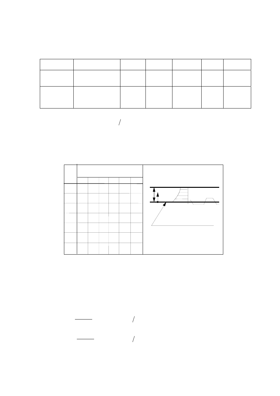
Page 72
Draft prEN1994-1-2:2003
Table B.4 : Coefficients for the determination of the limiting temperature.
Concrete
Fire resistance
[min]
d
0
[
o
C]
d
1
[
o
C] . N
d
2
[
o
C] . mm
d
3
[
o
C]
d
4
[
o
C] . mm
Normal
weight
concrete
60
90
120
867
1055
1144
-1,9·10
-4
-2,2·10
-4
-2,2·10
-4
-8,75
-9,91
-9,71
-123
-154
-166
-1378
-1990
-2155
Light weight
concrete
30
60
90
120
524
1030
1159
1213
-1,6·10
-4
-2,6·10
-4
-2,5·10
-4
-2,5·10
-4
-3,43
-10,95
-10,88
-10,09
-80
-181
-208
-214
-392
-1834
-2233
-2320
(6) The parameter
z
given in (5) may be solved from the equation for the determination of the rebar
temperature (i.e. equ. B.5), assuming
2
3
h
u
= 0,75 and using
lim
R
θ
θ
=
.
(7) In the case of
2
I
h
Y
>
, the ribs of the slab may be neglected. Table B.5 may be used to obtain the
location of the isotherm as a conservative approximation; for lightweight concrete, Table B.5 may be used
as well.
Table B.5:
Temperature distribution in a solid slab of 100 mm thickness composed of
normal weight concrete and not insulated.
h
eff
θ
c
Heated lower side
of slab
Depth
x
mm
Temperature θ [°C] after a fire
duration in min. of
30' 60' 90' 120' 180' 240'
5
10
15
20
25
30
35
40
45
50
55
60
80
100
C
535
470
415
350
300
250
210
180
160
140
125
110
80
60
705
642
581
525
469
421
374
327
289
250
200
175
100
140
738
681
627
571
519
473
428
387
345
294
271
220
160
754
697
642
591
542
493
454
415
369
342
270
210
738
689
635
590
330
260
469
430
549
508
395
305
520
495
645
550
740
700
670
x
(8) The hogging moment resistance is calculated by using the remaining cross section determined by (1)
to (7) and by referring to 4.3.1
(9) For light weight concrete, the temperatures of Table B.5 are reduced to 90% of the values given.
B.4
Effective thickness of a composite slab
(1) The effective
eff
h
is given by the formula:
+
+
+
=
3
1
2
1
2
1
eff
h
5
,
0
h
h
l
l
l
l
for
1
2
h
h
≤ 1,5 and
1
h
> 40 mm
+
+
+
=
3
1
2
1
1
eff
75
,
0
1
h
h
l
l
l
l
for
1
2
h
h
> 1,5 and
1
h
> 40 mm
The cross sectional dimensions of the slab
1
h
,
2
h
,
1
l
,
2
l
and
3
l
are given in Figures 4.1 and 4.2.

Page 73
Draft prEN1994-1-2:2003
(2) lf
1
3
2 l
l >
, the effective thickness may be taken equal to
1
h
.
(3) The relation between the fire resistance with respect to the thermal insulation criterion and the
minimum effective slab thickness
eff
h
is given in Table B.6 for common levels of fire resistance, where
3
h
is the thickness of the screed layer if any on top of the concrete slab.
Table B.6: Minimum effective thickness as a function of the standard fire resistance.
Standard Fire Resistance
Minimum effective thickness
eff
h
[mm]
R 30
R 60
R 90
R 120
R 180
R 240
60
80
100
120
150
175
-
3
h
-
3
h
-
3
h
-
3
h
-
3
h
-
3
h
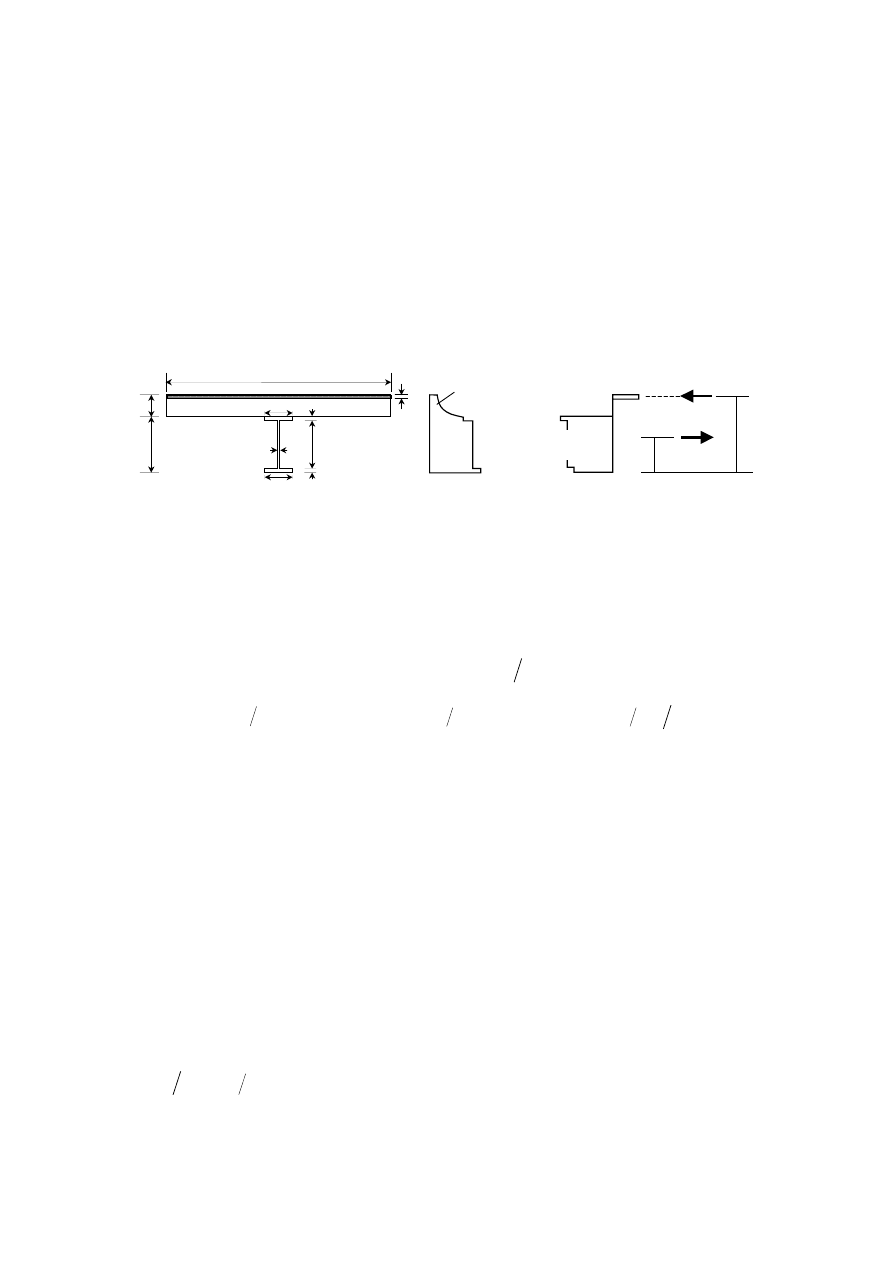
Page 74
Draft prEN1994-1-2:2003
Annex C
[informative]
Model for the calculation of the sagging and hogging moment
resistances of a steel beam connected to a concrete slab
and exposed to fire beneath the concrete slab.
θ
2
θ
1
θ
w
θ
c
(x)
h
u
a
,
fi
,
M
max,
a
/
f
γ
θ
2
a
,
fi
,
M
max,
a
/
f
w
γ
θ
a
,
fi
,
M
max,
a
/
f
γ
θ
1
h
c
h
e
w
h
w
b
1
e
1
b
2
e
2
eff
b
y
F
y
T
F
+
T
+
Compression
Tension
c
,
fi
,
M
C
,
c
/
f
γ
°
20
Figure C.1
C.1 Calculation of the sagging moment resistance
+
Rd
fi,
M
(1) According to Figure C.1 the tensile force
+
T
and its location
T
y
may be obtained from:
(
)
(
)
(
)
[
]
a
fi,
M,
2
2
2
amax,
w
w
w
amax,
1
1
1
amax,
e
b
f
e
h
f
+
e
b
f
T
γ
θ
θ
θ
+
=
+
( )
( )
(
)(
)
(
)(
)
[
]
(
)
a
fi,
M,
2
2
2
2
amax,
w
1
w
w
w
amax,
2
1
1
1
amax,
T
T
2
e
-
h
e
b
f
+
2
h
+
e
e
h
f
+
2
e
b
f
y
γ
θ
θ
θ
+
=
with
θ
max,
a
f
the maximum stress level according to 3.2.1 of EN 1993-1-2, at temperature
θ
, defined following
4.3.4.2.2.
(2) In a simply supported beam, the value of the tensile force
+
T
obtained from (1) is limited by:
Rd
,
fi
P
N
T
≤
+
where:
N
is the number of shear connectors in one of the critical lengths of the beam and
Rd
,
fi
P
is the design
shear resistance in the fire situation of a shear connector according to 4.3.4.2.5.
NOTE:
The critical lengths are defined by the end supports and the cross-section of maximum bending
moment.
(3) The thickness of the compressive zone
u
h
is determined from:
(
)
c
,
fi
,
M
c
eff
u
f
b
T
h
γ
+
=
where
eff
b
is the effective width according to 5.4.1.2 of EN 1994-1-1, and
c
f
the compressive strength of
concrete at room temperature.

Page 75
Draft prEN1994-1-2:2003
(4) Two situations may occur:
(
)
cr
u
c
h
h
h
≥
−
with
cr
h
is the depth x according to Table B.5 corresponding to a concrete temperature
below 250°C. In that situation (17) of 4.3.4.2.2 applies.
or
(
)
cr
u
c
h
h
h
<
−
; some layers of the compressive zone of concrete are at a temperature higher than
250°C. In this respect, a decrease of the compressive strength of concrete may be considered according
to 3.2.2.1 of EN 1992-1-2. This may be done by iteration assuming on the basis of Table B.5 an average
temperature for every slice of 10 mm thickness, such as:
(
)
( )
(
)
(
)
c
fi,
M,
1
-
n
2
=
i
n
c,
eff
n
u,
i
c,
eff
c
eff
cr
c
f
b
h
+
f
10b
+
f
b
h
-
h
F
T
γ
θ
θ
=
=
∑
+
where:
(
)
(
)
n
,
u
cr
c
u
h
2
n
10
h
h
h
+
−
+
−
=
[mm]
n
is the total number of concrete layers in compression, including the top concrete layer
(
)
cr
c
h
h
−
with a temperature below 250°C.
(5) The point of application of this compression force is obtained from
(
)
2
h
h
h
y
u
c
F
−
+
≈
and the sagging moment resistance is
(
)
T
F
Rd
,
fi
y
y
T
M
−
=
+
+
with
+
T
, the tensile force given by the smallest value from (1) or (4).
(6) This calculation model may be used for a composite slab with a profiled steel sheet, provided in (3) and (4),
c
h
is replaced by
eff
h
as defined in (1) of B.4 and
u
h
is limited by
1
h
as defined in Figures 4.1 and 4.2.
(7) This calculation model established in connection to 4.3.4.2.4, may be used for the critical temperature
model of 4.3.4.2.3 by assuming that
cr
2
w
1
θ
θ
θ
θ
=
=
=
.
(8) A similar approach may be used if the neutral axis is not inside the concrete slab but in the steel
beam.
C.2 Calculation of the hogging moment resistance
-
Rd
fi,
M
at an intermediate support (or
at a restraining support)
(1) The effective width of the slab at an intermediate support (or at the restraining support)
−
eff
b
may be
determined so that the plastic neutral axis does not lie in the concrete slab, i.e. the slab is assumed to be
cracked over its whole thickness. This effective width may not be larger than that determined at normal
temperature, according to 5.4.1.2 of EN 1994-1-1.
(2) The longitudinal tensile reinforcing bars may be assumed at the plastic yield
s
max,
s
f
θ
where
s
θ
is the
temperature in the slab, at the level where the reinforcing bars are located.
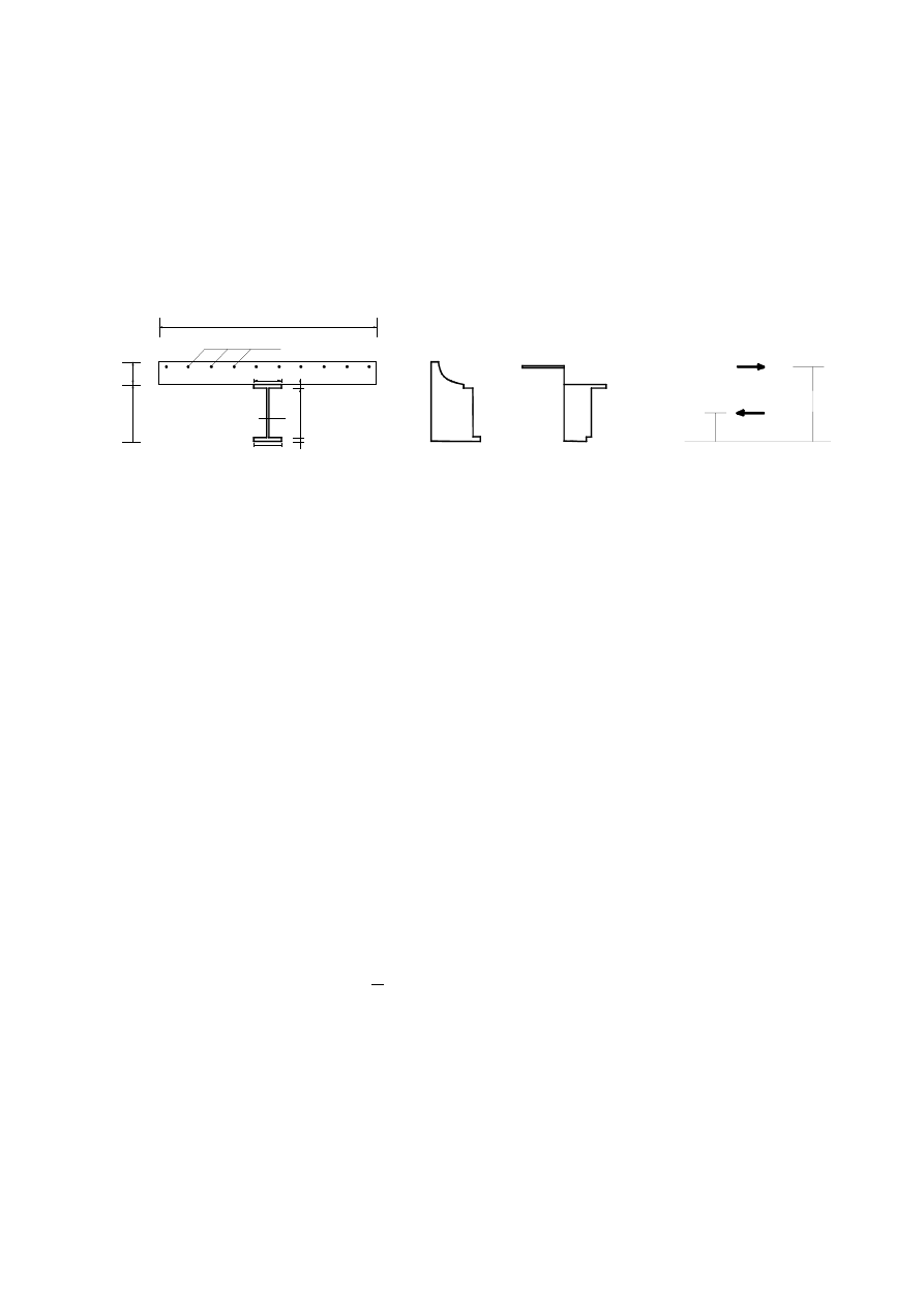
Page 76
Draft prEN1994-1-2:2003
(3) The following clauses assume that the plastic neutral axis is located just at the interface between the
slab and the steel section. A similar approach may be used if the plastic neutral axis is within the steel
cross section, by changing the formulae accordingly.
(4) The hogging plastic moment resistance of the composite section may be determined by considering
the stress diagram of Figure C.2, with temperatures
w
2
1
,
,
θ
θ
θ
calculated according to 4.3.4.2.2.
Tension
Compression
b
eff
−
A
s
h
c
h
b
2
h
w
e
2
e
1
e
w
b
1
θ
2
θ
w
θ
1
f
s
s
M fi
max
, ,s
( ) /
θ
γ
f
a
2
M fi
max
, ,a
(
) /
θ
γ
f
a
w
M fi
max
, ,a
(
) /
θ
γ
f
a
M fi
max
, ,a
( ) /
θ
γ
1
Y
F
−
Y
T
−
T
−
F
−
Figure C.2
(5) The hogging moment resistance is given by :
)
y
y
(
T
M
F
T
Rd
,
fi
−
−
−
−
=
−
where :
−
T
is the total tensile force of the reinforcing bars, equal to the compressive force
−
F
in the steel
section.
(6) The value of the compressive force
F
in the slab, at the critical cross section within the span,
see (2) of C.1, may be such as :
−
−
×
≤
T
P
N
F
Rd
,
fi
where:
N
is the number of shear connectors between the critical cross-section and the intermediate support
(or the restraining support) and where
Rd
,
fi
P
is the shear resistance of a shear connector in case of fire,
as mentioned in clause 4.3.4.2.5.
(7) The previous clauses may be used for cross sections of class 1 or 2 defined in the fire situation; for
sections of class 3 or 4 the following clauses (8) to (9) apply.
(8) When the steel web or the lower steel flange of the composite section is of class 3 in the fire situation,
its width may be reduced to an effective value adapted from EN 1993-1-5, where
y
f
and
E
are
respectively replaced by
θ
max,
a
f
and
θ
,
a
E
.
(9) When the steel web or the bottom steel flange of the composite section is of class 4 in the fire
situation, its resistance may be neglected.
C.3 Local resistance at supports
(1) The local resistance of the steel section shall be checked against the reaction force at the support (or
at the restraining support).
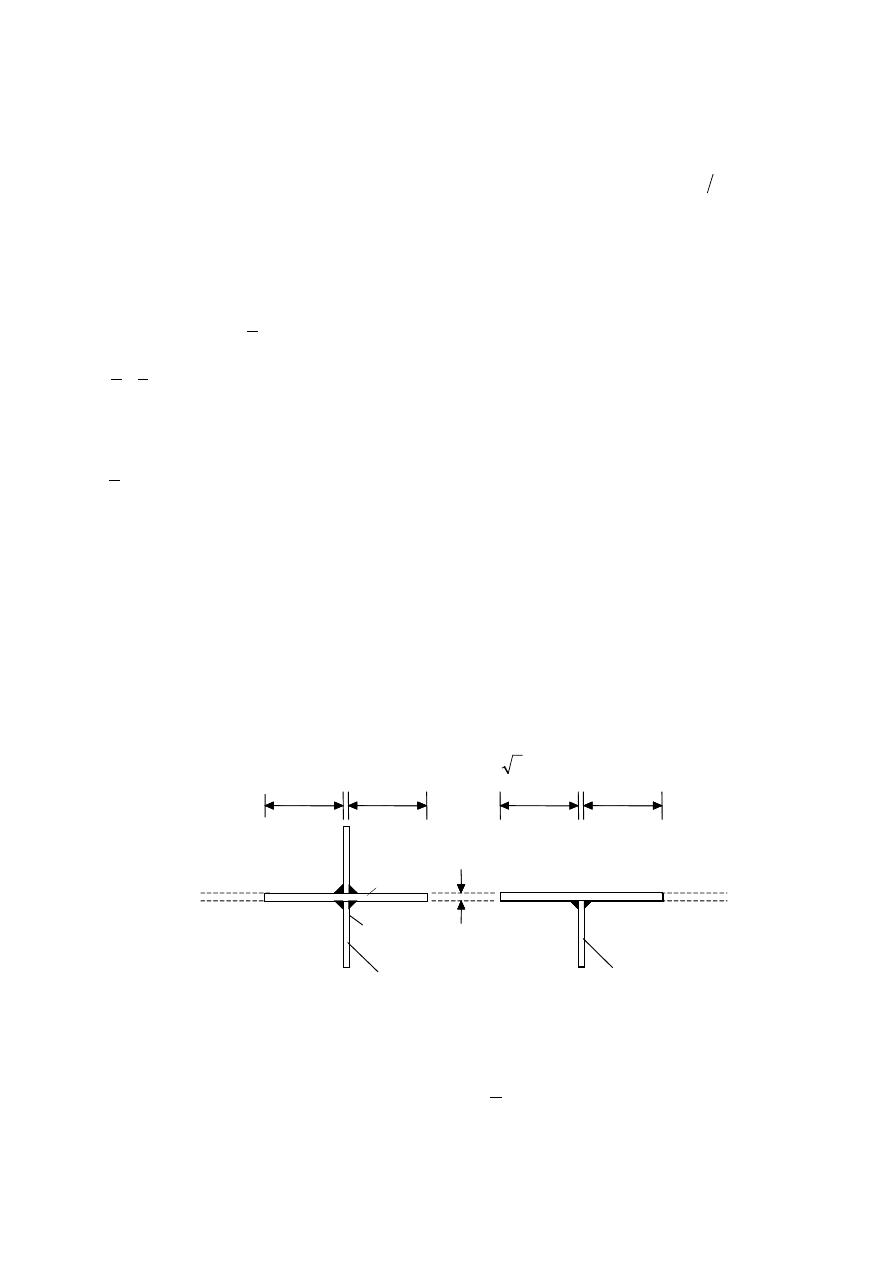
Page 77
Draft prEN1994-1-2:2003
(2) The temperature of stiffener
r
θ
is calculated by considering its own section factor,
r
r
V
A
, according
to 4.3.4.2.2.
(3) The local resistance of the steel section at the support (or at the restraining support) is taken equal to
the lower value of the buckling or the crushing resistance.
(4) For the calculation of the buckling resistance a maximum width of the web of 15
w
e
ε
on each side
of the stiffener (see Figure C.3) may be added to the effective cross section of the stiffener. The
relative slenderness
θ
λ
used to calculate buckling resistance is given by :
}
)
k
/
k
(
,
)
k
/
k
min{(
/
,
,
r
max,
r
,
E
w
max,
w
,
E
5
0
5
0
θ
θ
θ
θ
λ
λ
θ
=
where:
θ
,
E
k
and
θ
max,
k
is given in Table 3.1 of EN 1993-1-2 , and
λ
is the relative slenderness at room temperature for the stiffener associated with part of web as shown
in Figure E.3.
(5) For the calculation of the crushing resistance, the design crushing resistance, R
fi,y,Rd
, of the web with
the stiffeners is given by :
a
,
fi
,
M
r
max,
a
r
a
,
fi
,
M
w
max,
a
w
Rd
,
y
,
fi
/
f
A
/
f
e
)
r
e
(
s
R
s
γ
γ
θ
θ
+
+
+
=
1
5
where:
w
max,
a
f
θ
and
r
max,
a
f
θ
are respectively the maximum stresses in steel at the temperature of web
w
θ
and of
stiffener
r
θ
;
r is equal to the root radius for a hot rolled section, and to
2
a
with
a
the throat of fillet weld.
Figure C.3 : Stiffener on an intermediate support
C.4 Vertical shear resistance
(1) Clauses in 6.2.2 of EN 1994-1-1 may be used to check the vertical shear resistance of composite
beams in fire situation by replacing
a
E
,
ay
f
and
a
γ
by
θ
,
a
E
,
θ
max,
,
a
f
and
a
,
fi
,
M
γ
respectively as defined
in Table 3.1 of EN 1993-1-2 and clause 2.3(1)P.
Web (θ
w
)
15
ε
e
w
15 ε e
w
15 ε e
w
15 ε e
w
e
w
A
r
A
r
Stiffener (θ
r
)
15
ε
e
w
15 ε e
w
15 ε e
w
15 e
w
e
w
A
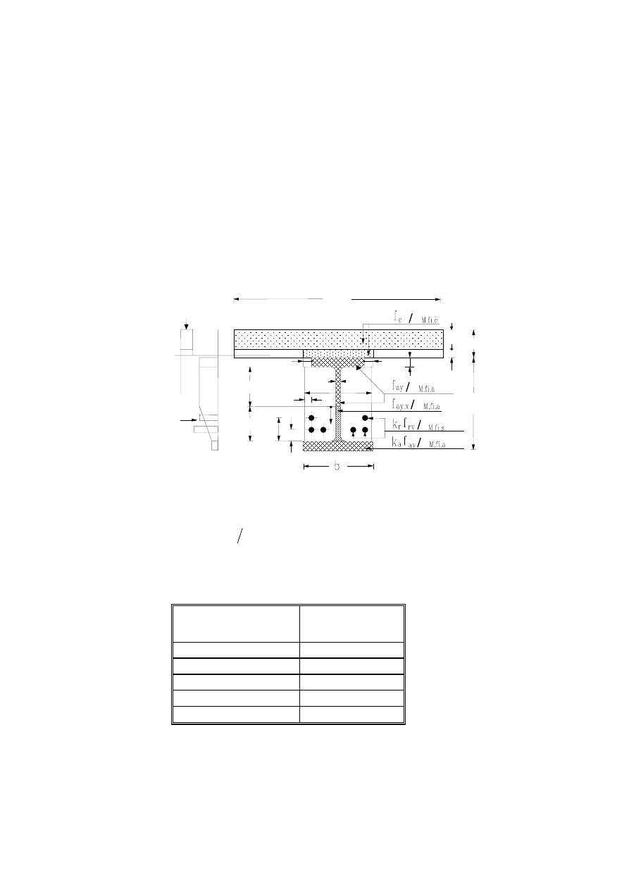
Page 78
Draft prEN1994-1-2:2003
Annex D
[informative]
Model for the calculation of the sagging and hogging moment
resistances of a partially encased steel beam connected
to a concrete slab and exposed to fire beneath the concrete slab
according to the standard temperature-time curve .
D.1 Reduced cross-section for sagging moment resistance
+
Rd
fi,
M
b
eff
h
x
_
+
_
+
2
1
3
u
s
γ
γ
γ
γ
γ
h
c
h
c,h
b
fi
b
fi
h
h
hl u
2
u
1,3
b
c
e
w
e
f
h
c,fi
Note to Figure D.1: (A) Example of stress distribution in concrete;
(B) Example of stress distribution in steel
Figure D.1
(1) The section of the concrete slab is reduced as shown in Figure D.1, but the design value of the
compressive concrete strength
c
,
fi
,
M
c
f
γ
is not varying in function of the fire classes. The values of the
thickness reduction
fi
,
c
h
of a flat concrete slab are given in Table D.1 for the different fire classes.
Table D.1: Thickness reduction
fi
,
c
h
of the concrete slab.
Standard Fire Resistance
Slab Reduction
fi
,
c
h
[mm]
R 30
10
R 60
20
R 90
30
R 120
40
R 180
55
(2) For other concrete slab systems the following rules apply:
- for trapezoidal steel sheets (see Figure 1.1) disposed transversally on the beam, the thickness
reduction
fi
,
c
h
of Table D.1 may be applied on the upper face of the steel deck (Figure D.2.a);
(A)
(B)
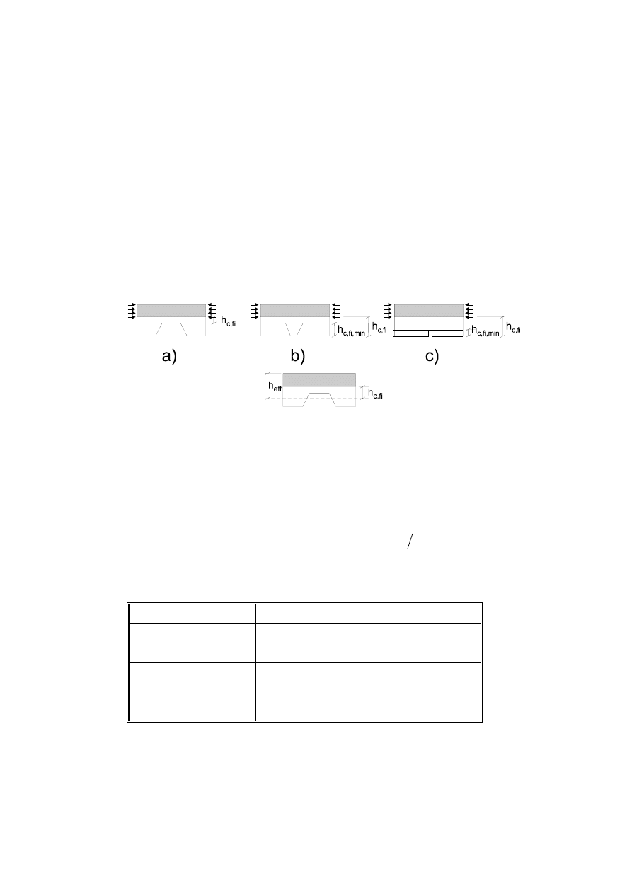
Page 79
Draft prEN1994-1-2:2003
- for re-entrant profiles (see Figure 1.1) disposed transversally on the beam, the thickness reduction
fi
,
c
h
of Table D.1 may be applied on the lower face of the steel deck. However, the value of
fi
,
c
h
may
not be smaller than the height of the deck profile (Figure D.2.b);
- when prefabricated concrete planks are used, the thickness reduction
fi
,
c
h
of Table D.1 may be
applied on the lower face of the concrete plank, but may not be smaller than the height of the joint,
between precast elements, unable to transmit a compression stress (Figure D.2.c);
- for re-entrant profiles parallel to the beam, the thickness reduction
fi
,
c
h
of Table D.1 applies on the
lower face of the steel deck;
- for trapezoidal steel sheets parallel to the beam, the thickness reduction
fi
,
c
h
of Table D.1 may be
applied on the effective height of the slab
eff
h
(see Figure D.2.d), where the effective thickness of the
slab
eff
h
is given in Figures 4.1, 4.2 and in B.4 of Annex B.
d)
Figure D.2
(3) The temperature
c
θ
of the concrete layer
fi
,
c
h
situated directly on top of the upper flange, may be
assumed to be 20°C.
(4) The active width of the upper flange of the profile (b-2b
fi
) is varying in function of the fire classes, but
the design value of the yield point of the steel is taken equal to
a
,
fi
,
M
ay
f
γ
. The values of the flange
width reduction
fi
b
are given in Table D.2 for the different fire classes.
Table D.2: Width reduction b
fi
of the upper flange
Standard Fire Resistance Width Reduction b
fi
of the Upper Flange [mm]
R 30
(e
f
/ 2) + (b - b
c
) / 2
R 60
(e
f
/ 2) + 10 + (b - b
c
) / 2
R 90
(e
f
/ 2) + 30 + (b - b
c
) / 2
R 120
(e
f
/ 2) + 40 + (b - b
c
) / 2
R 180
(e
f
/ 2) + 60 + (b - b
c
) / 2
(5) The web is divided into two parts, the top part hh and the bottom part h
l
. The values of h
l
are given
for the different fire classes by the formula h
l
= a
1
/ b
c
+ a
2
e
w
/ (b
c
h). Parameters a
1
and a
2
are given in
Table D.3 for h / b
c
≤ 1 or h / b
c
≥ 2.
The bottom part h
l
is given directly in Table D.3 for 1 < h / b
c
< 2.

Page 80
Draft prEN1994-1-2:2003
Table D.3: Bottom part of the web h
l
[mm] and h
l,min
[mm], with h
l,max
equal to (h - 2e
f
).
Standard
Fire
Resistance
a
1
[mm²]
a
2
[mm²]
h
l min
[mm]
R 30
3 600
0
20
R 60
9 500
20 000
30
h / b
c
≤ 1
R 90
14 000
160 000
40
R 120
23 000
180 000
45
R 180
35 000
400 000
55
R 30
3 600
0
20
R 60
9 500
0
30
h / b
c
≥ 2
R 90
14 000
75 000
40
R 120
23 000
110 000
45
R 180
35 000
250 000
55
R 30
h
l
= 3 600 / b
c
20
R 60
h
l
= 9 500 / b
c
+ 20 000 (e
w
/ b
c
h) (2 - h / b
c
)
30
1 < h / b
c
< 2
R 90
h
l
= 14 000 / b
c
+ 75 000 (e
w
/ b
c
h)
+ 85 000 (e
w
/ b
c
h) (2 - h / b
c
)
40
R 120
h
l
= 23 000 / b
c
+ 110 000 (e
w
/ b
c
h)
+ 70 000 (e
w
/ b
c
h) (2 - h / b
c
)
45
R 180
h
l
= 35 000 / b
c
+ 250 000 (e
w
/ b
c
h)
+ 150 000 (e
w
/ b
c
h) (2 - h / b
c
)
55
(6) The bottom part h
l
of the web may always be larger or equal than h
l,min
given in Table D.3.
(7) For the top part h
h
of the web, the design value of the yield point of the steel is taken equal to
a
,
fi
,
M
ay
f
γ
. For the bottom part h
l
, the design value of the yield point depends on the distance x
measured from the end of the top part of the web (see Figure D.1). The reduced yield point in h
l
may be
obtained from:
(
)
[
]
l
h
/
k
1
x
1
f
f
a
ay
x
,
ay
−
−
=
where:
a
k
is the reduction factor of the yield point of the lower flange given in (8). This leads to a trapezoidal
form of the stress distribution in h
l
.
(8) The area of the lower flange of the steel profile is not modified. Its yield point is reduced by the factor
a
k
given in Table D.4. The reduction factor
a
k
is limited by the minimum and maximum values given in
this table.
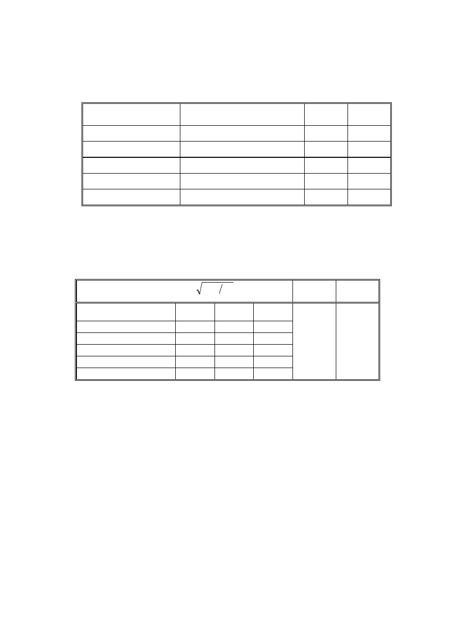
Page 81
Draft prEN1994-1-2:2003
Table D.4: Reduction factor k
a
of the yield point of the lower flange, with a
0
= (0,018 e
f
+ 0,7).
Standard Fire Resistance
Reduction Factor k
a
k
a,min
k
a,max
R 30
[(1,12) - (84 / b
c
) + (h / 22b
c
)]a
0
0,5
0,8
R 60
[(0,21) - (26 / b
c
) + (h / 24b
c
)]a
0
0,12
0,4
R 90
[(0,12) - (17 / b
c
) + (h / 38b
c
)]a
0
0,06
0,12
R 120
[(0,1) - (15 / b
c
) + (h / 40b
c
)]a
0
0,05
0,10
R 180
[(0,03) - (3 / b
c
) + (h / 50b
c
)]a
0
0,03
0,06
(9) The yield point of the reinforcing bars decreases with their temperature. Its reduction factor
r
k
is
given in Table D.5 and depends on the fire class and on the position of the reinforcing bar. The reduction
factor
r
k
is limited by the minimum and maximum values given in this table.
Table D.5: Reduction factor k
r
of the yield point of a reinforcing bar with
kr = (ua
3
+ a
4
)a
5
/
(
)
V
A
m
k
r,min
k
r,max
Standard Fire Resistance
a
3
a
4
a
5
R 30
0,062
0,16
0,126
R 60
0,034
- 0,04
0,101
0,1
1
R 90
0,026
- 0,154
0,090
R 120
0,026
- 0,284
0,082
R 180
0,024
- 0,562
0,076
where:
A
m
=
2h + b
c
[mm]
V =
h b
c
[mm²]
u = 1 / [(1/u
i
) + (1/u
si
) + 1/(b
c
-e
w
-u
si
)]
where:
u
i
is the axis distance [mm] from the reinforcing bar to the inner side of the flange and
u
si
is the axis distance [mm] from the reinforcing bar to the outside border of the concrete (see Figure D.1).
(10) The concrete cover of reinforcing bars may fulfill (5) of 5.1.
(11) The shear resistance of the steel web may be verified using the distribution of the design values of
yield strength according to (7). If
Rd
,
pl
,
fi
Sd
,
fi
V
5
,
0
V
≥
the resistance of the reinforced concrete may be
considered.
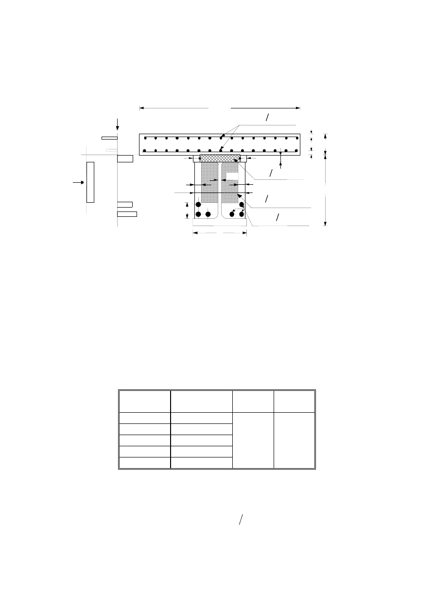
Page 82
Draft prEN1994-1-2:2003
D.2 Reduced cross-section for hogging moment resistance
-
Rd
fi,
M
Note to Figure D.3:
(A) Example of stress distribution in concrete;
(B) Example of stress distribution in steel
Figure D.3
(1) The yield point of the reinforcing bars in the slab is multiplied by a reduction factor
s
k
given in
Table D.6 and depends on the fire class and on the position of the reinforcing bars. The reduction factor
s
k
is limited by the minimum and maximum values given in this table.
Table D.6: Reduction factor k
s
of the yield point of the reinforcing bars in the concrete slab with
u, distance [mm] from the center of the reinforcement to the lower slab edge, equal to
u
l
or (h
c
- u
h
) (see Figure D.3).
Standard Fire
Resistance
Reduction Factor
k
s
k
s,min
k
s,max
R 30
1
R 60
(0,022 u) + 0,34
R 90
(0,0275 u) - 0,1
0
1
R 120
(0,022 u) - 0,2
R 180
(0,018 u) - 0,26
(2) For the upper flange of the profile, (4) of D.1 applies.
(3) The cross-section of the concrete between the flanges is reduced as shown in Figure D.3 but the
design value of the compressive concrete strength
c
,
fi
,
M
c
f
γ
is not varying in function of the fire
classes. The values of the width reduction
fi
,
c
b
and of the height reduction h
fi
of the encased concrete
are given in Table D.7. The width and height reductions are limited by the minimum values given in this
table.
3 · b
b
h
b
fi
b
b
c
h
c
u
l
e
f
u
h
b
c,fi
b
c,fi
h
fi
e
w
(A)
(B)
k
r
f
ry
γ
M,fi,s
f
c
γ
M,fi,c
f
ay
γ
M,fi,a
k
s
f
sy
γ
M,fi,s
+
fi
+
-
-
-
-

Page 83
Draft prEN1994-1-2:2003
Table D.7: Reduction of the cross-section of the concrete encased between the flanges.
Standard Fire Resistance
h
fi
[mm]
h
fi,min
[mm]
R 30
25
25
R 60
165 - (0,4b
c
) - 8 (h / b
c
)
30
R 90
220 - (0,5b
c
) - 8 (h / b
c
)
45
R 120
290 - (0,6b
c
) - 10 (h / b
c
)
55
R 180
360 - (0,7b
c
) - 10 (h / b
c
)
65
Standard Fire Resistance
b
c,fi
[mm]
b
c,fi,min
[mm]
R 30
25
25
R 60
60 - (0,15b
c
)
30
R 90
70 - (0,1b
c
)
35
R 120
75 - (0,1b
c
)
45
R 180
85 - (0,1b
c
)
55
(4) For the reinforcing bars situated in the concrete of the partially encased profile, (9) of D.1 applies.
(5) The concrete cover of reinforcing bars may fulfill (5) of 5.1.
(6) In the areas with hogging bending moments, the shear force is assumed to be transmitted by the steel
web, which is neglected when calculating the hogging bending moment resistance.
(7) The shear resistance of the steel web may be verified using the distribution of the design values of
yield strength according to (7) of D.1.
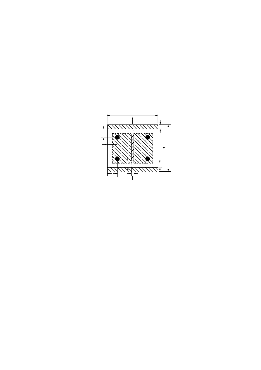
Page 84
Draft prEN1994-1-2:2003
Annex E
[informative]
Balanced summation model for the calculation of the fire resistance
of composite columns with partially encased steel sections, for
bending around the weak axis, exposed to fire all around the column
according to the standard temperature-time curve .
Z
Y
h
b
c,fi
e
f
h
w,fi
b
c,fi
b
e
w
u
2
u
1
Figure E.1: Reduced cross-section for structural fire design
E.1 Introduction
(1) This calculation model is based on the principles and rules given in 4.3.5.1, but has been developed
only for bending around the axis Z such as:
Rd
,
pl
,
fi
z
z
,
Rd
,
fi
N
N
χ
=
(2) For the calculation of the design value of the plastic resistance to axial compression
Rd
,
pl
,
fi
N
and of
the effective flexural stiffness
z
,
eff
,
fi
)
EI
(
in the fire situation, the cross-section is divided into four
components:
- the flanges of the steel profile;
- the web of the steel profile;
- the concrete contained by the steel profile and
- the reinforcing bars.
(3) Each component may be evaluated on the basis of a reduced characteristic strength, a reduced
modulus of elasticity and a reduced cross-section in function of the standard fire resistance R30, R60,
R90 or R120.
(4) The design value of the plastic resistance to axial compression and the effective flexural stiffness of
the cross-section may be obtained, according to (4) and (5) of 4.3.5.1, by a balanced summation of the
corresponding values of the four components.

Page 85
Draft prEN1994-1-2:2003
(5) Strength and deformation properties of steel and concrete at elevated temperatures complies with the
corresponding principles and rules of 3.1 and 3.2.
E.2 Flanges of the steel profile
(1) The average flange temperature may be determined from:
(
)
V
A
k
m
t
t,
o
t,
f
+
=
θ
θ
where:
t
is the duration in minutes of the fire exposure
V
A
m
is the section factor in m
-1
, with A
m
= 2 (h + b) in [m] and V = h b in [m²]
t,
o
θ
is a temperature in °C given in Table E.1
t
k
is an empirical coefficient given in Table E.1.
Table E.1
Standard Fire Resistance
t,
o
θ
[°C]
t
k
[m°C]
R30
550
9,65
R60
680
9,55
R90
805
6,15
R120
900
4,65
(2) On behalf of the temperature
t,
f
θ
θ
=
the corresponding maximum stress level and the modulus of
elasticity are determined from:
θ
max,
f
,
ay
t,
f
max,
a
k
f
f
=
and
θ
,
E
f
,
a
t,
f
,
a
k
E
E
=
with
θ
max,
k
and
θ
,
E
k
following Table 3.1 of EN 1993-1-2
(3) The design value of the plastic resistance to axial compression and the flexural stiffness of the two
flanges of the steel profile in the fire situation are determined from:
(
)
a
,
fi
,
M
t,
f
max,
a
f
f
,
Rd
,
pl
,
fi
f
e
b
2
N
γ
=
and
(
)
6
b
e
E
)
EI
(
3
f
t,
f
,
a
z
,
f
,
fi
=
E.3 Web of the steel profile
(1) The part of the web with the height
fi
,
w
h
and starting at the inner edge of the flange may be neglected
(see Figure E.1). This part is determined from:
(
)
(
)
(
)
h
H
0,16
-
1
1
e
2
h
5
,
0
h
t
f
fi
,
w
−
−
=
where
t
H
is given in Table E.2.
Page 86
Draft prEN1994-1-2:2003
Table E.2
Standard Fire Resistance
t
H
[mm]
R 30
350
R 60
770
R 90
1100
R 120
1250
(2) The maximum stress level is obtained from:
(
)
h
0,16H
-
1
f
f
t
w
,
ay
t,
w
max,
a
=
(3) The design value of the plastic resistance to axial compression and the flexural stiffness of the web of
the steel profile in the fire situation are determined from:
(
)
[
]
a
,
fi
,
M
t,
w
max,
a
fi
,
w
f
w
w
,
Rd
,
pl
,
fi
f
h
2
e
2
h
e
N
γ
−
−
=
(
)
[
]
12
e
h
2
e
2
h
E
)
EI
(
3
w
fi
,
w
f
w
,
a
z
,
w
,
fi
−
−
=
E.4 Concrete
(1) An exterior layer of concrete with a thickness
fi
,
c
b
may be neglected in the calculation (see
Figure E.1). The thickness
fi
,
c
b
is given in Table E.3, with
V
A
m
, the section factor in m
-1
of the entire
composite cross-section.
Table E.3
Standard Fire Resistance
fi
,
c
b
[mm]
R30
R60
R90
R120
4,0
15,0
0,5 (
V
A
m
) + 22,5
2,0 (
V
A
m
) + 24,0
(2) The average temperature in concrete
t,
c
θ
is given in Table E.4 in function of the section factor
V
A
m
of the entire composite cross-section and for the standard fire resistance classes.
Table E.4
R30
R60
R90
R120
V
A
m
[m
-1
]
t,
c
θ
[°C]
V
A
m
[m
-1
]
t,
c
θ
[°C]
V
A
m
[m
-1
]
t,
c
θ
[°C]
V
A
m
[m
-1
]
t,
c
θ
[°C]
4
23
46
-
-
-
-
136
300
400
-
-
-
-
4
9
21
50
-
-
-
214
300
400
600
-
-
-
4
6
13
33
54
-
-
256
300
400
600
800
-
-
4
5
9
23
38
41
43
265
300
400
600
800
900
1000
Page 87
Draft prEN1994-1-2:2003
(3) On behalf of the temperature
t,
c
θ
θ
=
the secant modulus of concrete is obtained from:
θ
θ
θ
θ
θ
ε
ε
,
cu
,
c
c
,
cu
,
c
sec,
,
c
k
f
f
E
=
=
with
θ
,
c
k
and
θ
ε
,
cu
following Table 3.1 of EN 1992-1-2
(4) The design value of the plastic resistance to axial compression and the flexural stiffness of the
concrete in the fire situation are determined from:
(
)(
)
(
)
{
}
c
,
fi
,
M
,
c
s
fi
,
c
w
fi
,
c
f
c
,
Rd
,
pl
,
fi
f
A
b
2
e
b
b
2
e
2
h
86
,
0
N
γ
θ
−
−
−
−
−
=
where A
s
is the cross-section of the reinforcing bars, and 0,86 is a calibration factor.
( )
(
)(
)
(
)
{
}
[
]
z
,
s
3
w
3
fi
,
c
fi
,
c
f
sec,
,
c
z
,
c
,
fi
I
12
e
b
2
b
b
2
e
2
h
E
EI
−
−
−
−
−
=
θ
where
z
,
s
I
is the second moment of area of the reinforcing bars related to the central axis Z of the
composite cross-section.
E.5 Reinforcing
bars
(1) The reduction factor
t,
y
k
of the yield point and the reduction factor
t,
E
k
of the modulus of elasticity of
the reinforcing bars, are defined in function of the standard fire resistance and the geometrical average
u
of the axis distances of the reinforcement to the outer borders of the concrete (see Tables E.5 and
E.6).
Table E.5: Reduction factor k
y,t
for the yield point f
sy
of the reinforcing bars
u[mm]
Standard
Fire Resistance
40
45
50
55
60
R30
1
1
1
1
1
R60
0,789
0,883
0,976
1
1
R90
0,314
0,434
0,572
0,696
0,822
R120
0,170
0,223
0,288
0,367
0,436
Table E.6: Reduction factor k
E,t
for the modulus of elasticity E
s
of the reinforcing bars
u[mm]
Standard
Fire Resistance
40
45
50
55
60
R30
0,830
0,865
0,888
0,914
0,935
R60
0,604
0,647
0,689
0,729
0,763
R90
0,193
0,283
0,406
0,522
0,619
R120
0,110
0,128
0,173
0,233
0,285
(2) The geometrical average u of the axis distances
1
u
and
2
u
is obtained from:
2
1
u
u
u
⋅
=
where:
1
u
is the axis distance from the outer reinforcing bar to the inner flange edge
[mm]
2
u
is the axis distance from the outer reinforcing bar to the concrete surface
[mm]
Page 88
Draft prEN1994-1-2:2003
Note:
If
(
)
2
1
u
-
u
> 10 mm, then
(
)
10
+
u
u
u
2
2
=
,
or
(
)
1
2
u
-
u
> 10 mm, then
(
)
10
+
u
u
u
1
1
=
.
(3) The design value of the plastic resistance to axial compression and the flexural stiffness of the
reinforcing bars in the fire situation are obtained from:
s
,
fi
,
M
sy
t,
y
s
s
,
Rd
,
pl
,
fi
f
k
A
N
γ
=
( )
z
,
s
s
t,
E
z
,
s
,
fi
I
E
k
EI
=
E.6 Calculation of the axial buckling load at elevated temperatures
(1) According to (4) of E.1, the design value of the plastic resistance to axial compression and the
effective flexural stiffness of the cross-section in the fire situation are determined from:
s
,
Rd
,
pl
,
fi
c
,
Rd
,
pl
,
fi
w
,
Rd
,
pl
,
fi
f
,
Rd
,
pl
,
fi
Rd
,
pl
,
fi
N
N
N
N
N
+
+
+
=
( )
( )
( )
( )
( )
z
,
s
,
fi
,
s
z
,
c
,
fi
,
c
z
,
w
,
fi
,
w
z
,
f
,
fi
,
f
z
,
eff
,
fi
EI
EI
EI
EI
EI
θ
θ
θ
θ
ϕ
ϕ
ϕ
ϕ
+
+
+
=
where
θ
ϕ
i,
is a reduction coefficient depending on the effect of thermal stresses. The values of
θ
ϕ
i,
are
given in Table E.7.
Table E.7
Standard Fire Resistance
θ
ϕ
f,
θ
ϕ
w,
θ
ϕ
c,
θ
ϕ
s,
R30
1,0
1,0
0,8
1,0
R60
0,9
1,0
0,8
0,9
R90
0,8
1,0
0,8
0,8
R120
1,0
1,0
0,8
1,0
(2) The Euler buckling load or elastic critical load follows by:
( )
2
z
,
eff
,
fi
z
,
cr
,
fi
EI
²
N
θ
π
l
=
where:
θ
l
is the buckling length of the column in the fire situation.
(3) The non-dimensional slenderness ratio is obtained from:
cr,z
fi,
R
pl,
fi,
N
N
=
θ
λ
where:
R
,
pl
,
fi
N
is the value of
Rd
,
pl
,
fi
N
according to (1) when the factors
c
,
fi
,
M
a
,
fi
,
M
,
γ
γ
and
s
,
fi
,
M
γ
are taken
as 1,0.

Page 89
Draft prEN1994-1-2:2003
(4) Using
λ
θ
and the buckling curve c of EN 1993-1-1, the reduction coefficient
z
χ
may be calculated
and the design axial buckling load in the fire situation is obtained from:
Rd
,
pl
,
fi
z
z
,
Rd
,
fi
N
N
χ
=
(5) Limitations of the method of this Annex are given as follows for the different standard fire resistance
classes:
R30:
b and h
≥ 230 mm →
θ
l
≤ 13,5b
R60:
for
230 mm
≤ b < 300 mm or h/b > 3
→
θ
l
≤ 10b
for
b
≥ 300 mm and h/b ≤ 3 →
θ
l
≤ 13,5b
R90
and
R120
b
≥ 300 mm and h ≥ 300 mm
for h / b > 3
→
θ
l
≤ 10b
for h / b
≤ 3 →
θ
l
≤ 13,5b
(6) The design values of the resistance of members in axial compression or the design axial buckling
loads
z
,
Rd
,
fi
N
are shown in Figures E.2 and E.3 in function of the buckling length
θ
l
for the profile series
HEA and the material grades S355 of the steel profile, C40/50 of the concrete, S500 of the reinforcing
bars and for the different standard fire resistance classes R60, R90 and R120.
These design graphs are based on the partial material safety factors
0
,
1
c
,
fi
,
M
s
,
fi
,
M
a
,
fi
,
M
=
=
=
γ
γ
γ
.
E.7 Eccentricity of loading
(1) For a column submitted to a load with an eccentricity
δ, the design buckling load
δ
,
Rd
,
fi
N
may be
obtained from:
(
)
Rd
,
Rd
Rd
,
fi
,
Rd
,
fi
N
N
N
N
δ
δ
=
where:
Rd
N
and
δ
,
Rd
N
represent the axial buckling load and the buckling load in case of an eccentric load
calculated according to EN 1994-1-1, for normal temperature design.
(2) The application point of the eccentric load remains inside the composite cross-section of the column.
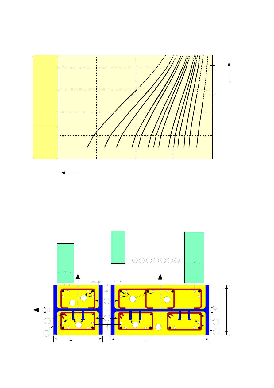
Page 90
Draft prEN1994-1-2:2003
1
H
E
24
0 A
2
H
E
28
0 A
3
H
E
32
0 A
4
H
E
36
0 A
5
H
E
40
0 A
6
H
E
45
0 A
7
H
E
50
0 A
8
H
E
55
0 A
9
H
E
60
0 A
10
H
E
65
0 A
11
H
E
70
0 A
12
H
E
80
0 A
13
H
E
90
0 A
14
H
E
10
00
A
+4
ø2
0
(R
)
+4
ø2
5
(R
)
+4
ø2
5
(R
)
+8
ø2
0
(R
+S
)
+8
ø2
0
(R
+S
)
8ø
20
(R
)
+
12
ø2
0
(R
+S
)
+
12
ø2
0
(R
+S
)
+
12
ø2
0
(R
+S
)
+
16
ø2
0
(R
+S
)
+
16
ø2
0
(R
+S
)
+
20
ø2
0
(R
+S
+T
)
+
20
ø2
0
(R
+S
+T
)
+
16
ø2
5
(R
+S
)
+
12
3
4
4,
5
5
10
15
20
1
2
3
4
5
6
7
8
9
10
11
12
13
14
2,
4
2,
8
4,
05
DESIGN AXIAL BUCKLING LOAD N
fi,Rd,z
[MN]
St
an
d
ar
d F
ir
e
Re
si
st
an
ce
R 6
0
St
ru
ct
u
ra
l St
ee
l G
ra
de
: S
355
Co
nc
re
te
G
ra
de
: S
500
Gr
ad
e o
f R
ei
n
fo
rc
in
g B
ar
s
: C 4
0 /
5
0
B
U
C
K
L
ING
L
E
NG
T
H
l
θ
[m
]
Z
q
Y
Z
φ
Y
T; 4
R; 4
S;
4
4,
8 o
r
12
REIN
FO
RCIN
G
BA
R
S
T; 4
S;
4 t
o 8
R; 8
8,
12
, 16
or
2
0
BA
R
S
REIN
FO
RCIN
G
φ
b
RO
LLED
P
R
O
F
IL
E
WELD
ED
S
T
IRRU
PS
STEEL M
E
SH
-B
A
SK
E
T
SH
E
A
R
ST
U
D
S
REI
N
FO
RCI
N
G
BA
RS
(
D
IA
M
ETER
CO
N
ST
R
U
C
TIO
N
A
L
REIN
FO
RC
IN
G
BA
RS
CO
N
CRETE
1
2
3
4
5
6
7
φ
)
u
1
60
=
u
2
60
=
u
1
60
=
h > 400 mm
h < 400 mm
qm
m
=≥
20
φ
qm
m
=≥
φ
20
1
6
4
7
5
3
2
5
4
7
7
1
6
Figure E.2
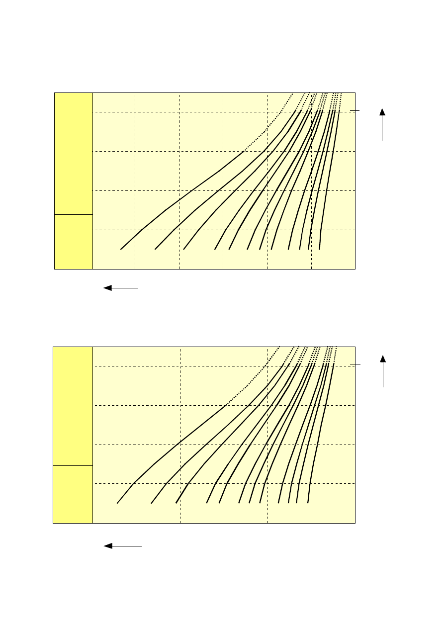
Page 91
Draft prEN1994-1-2:2003
123
4
4.
5
3
4
5
6
7
8
9
10
11
12
13
14
8
10
6
4
4.
05
1
2
3
4
4.
5
5
10
15
DESIGN AXIAL BUCKLING LOAD N
fi,Rd,z
[MN]
3
4
5
6
7
8
9
10
11
12
13
14
4.
05
B
U
C
K
L
ING
L
E
NG
T
H
[m
]
B
U
C
K
L
ING
L
E
NG
T
H
l
θ
[m
]
St
an
d
ar
d F
ir
e
Re
si
st
an
ce
R
120
St
ru
ct
u
ra
l St
ee
l G
ra
de
Co
nc
re
te
G
ra
de
Gr
ad
e o
f R
ei
n
fo
rc
in
g B
ar
s
: S
355
: S
500
: C 4
0 /
5
0
St
an
d
ar
d F
ir
e
Re
si
st
an
ce
R 9
0
St
ru
ct
u
ra
l St
ee
l G
ra
de
Co
nc
re
te
G
ra
de
Gr
ad
e o
f R
ei
n
fo
rc
in
g B
ar
s
: S
355
: S
500
: C 4
0 /
5
0
2
12
DESIGN AXIAL BUCKLING LOAD N
fi,Rd,z
[MN]
l
θ
Figure E.3

Page 92
Draft prEN1994-1-2:2003
Annex F
[informative]
Simple calculation model for concrete filled hollow sections
exposed to fire all around the column according to
the standard temperature-time curve.
F.1 Introduction
(1) The calculation model to determine the design value of the resistance of a concrete filled hollow
section column in axial compression and in the fire situation, is divided in two independent steps:
- calculation of the field of temperature in the composite cross-section after a given duration of fire
exposure and
- calculation of the design axial buckling load
Rd
,
fi
N
for the field of temperature previously obtained.
F.2 Temperature
distribution
(1) The temperature distribution shall be calculated in accordance with 4.4.2
(2) In calculating the temperature distribution, the thermal resistance between the steel wall and the
concrete may be neglected.
F.3 Design axial buckling load at elevated temperature
(1) For concrete filled hollow sections, the design axial buckling load
Rd
,
fi
N
may be obtained from:
Rd
,
pl
,
fi
cr
,
fi
Rd
,
fi
N
N
N
=
=
where:
[
]
2
s
,
,
s
c
,
,
c
a
,
,
a
cr
,
fi
I
E
I
E
I
E
²
N
θ
σ
θ
σ
θ
σ
θ
π
l
+
+
=
and
s
,
fi
,
M
,
s
s
c
,
fi
,
M
,
c
c
a
,
fi
,
M
,
a
a
Rd
,
pl
,
fi
A
A
A
N
γ
σ
γ
σ
γ
σ
θ
θ
θ
+
+
=
and where
cr
,
fi
N
is the elastic critical or Euler buckling load,
Rd
,
pl
,
fi
N
is the design value of the plastic resistance to axial compression of the total cross-section,
θ
l
is the buckling length in the fire situation,
σ
θ
,
,
i
E
is the tangent modulus of the stress-strain relationship for the material i at temperature
θ
and
for a stress
θ
σ
,
i
, (see Figure 3.1 of EN 1993-1-2 and Figure 3.1 of EN 1992-1-2 )
i
I
is the second moment of area of the material i, related to the central axis y or z of the composite
cross-section,
i
A
is the cross-section area of material i,
θ
σ
,
i
is the stress in material i, at the temperature
θ
.

Page 93
Draft prEN1994-1-2:2003
(2)
i
,
,
i
I
.
E
σ
θ
and
θ
σ
,
i
i
.
A
are calculated as a summation of all elementary elements dy dz having the
temperature
θ
after a fire duration t.
(3) The values of
t,
i
E
and
t,
i
σ
to be used comply with:
ε
ε
ε
ε
=
=
=
s
c
a
where:
ε
is the axial strain of the column and
i
ε
is the axial strain of the material i of the cross-section.
(4) The design axial buckling loads
Rd
,
fi
N
may be given in design graphs, like those of Figures F.3 and
F.4, in function of the relevant physical parameters.
NOTE:
The normal procedure is to increase the strain in steps. As the strain increases
t,
i
E
and
cr
,
fi
N
decrease and
t,
i
σ
and
Rd
,
pl
,
fi
N
increase. The level of strain is found where
cr
,
fi
N
and
Rd
,
pl
,
fi
N
are equal
and the condition in (1) is satisfied.
F.4 Eccentricity of loading
(1) In the fire situation the ratio between bending moment and axial force,
δ
=
N
/
M
, at the end of a
column, is not exceeding 0,5 times the size
b
or
d
of the cross-section.
(2) In case of an eccentricity
δ
of loading, the equivalent axial load
equ
N
to be used in connection with
the axial load design graphs in the fire situation may be obtained from:
(
)
δ
ϕ
ϕ
.
N
N
s
Sd
,
fi
equ
=
where:
s
ϕ
is given by Figure F.1 and
δ
ϕ
by Figure F.2., and
θ
l
is the buckling length,
b
is the size of a square section,
d
is the diameter of a circular section,
δ
is the eccentricity of the load.
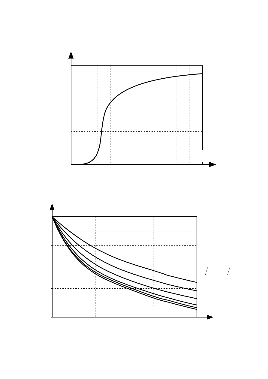
Page 94
Draft prEN1994-1-2:2003
0.4
0.5
0.6
0.7
0.8
0.9
1.0
0.0
0.5
1.0
1.5
2.0
2.5
3.0
3.5
4.0
4.5
5.0
ϕ
s
%
Figure F.1: Correction coefficient
ϕ
s
in function of the percentage of reinforcement
0.3
0.4
0.5
0.6
0.7
0.8
0.9
1.0
0.00
0.05
0.10
0.15
0.20
0.25
0.30
0.35
0.40
0.45
0.50
ϕ
δ
40
35
30
25
20
10
δ/b or δ/d
d
or
b
l
l
θ
θ
Figure F.2: Correction coefficient
ϕ
δ
in function of the eccentricity
δ
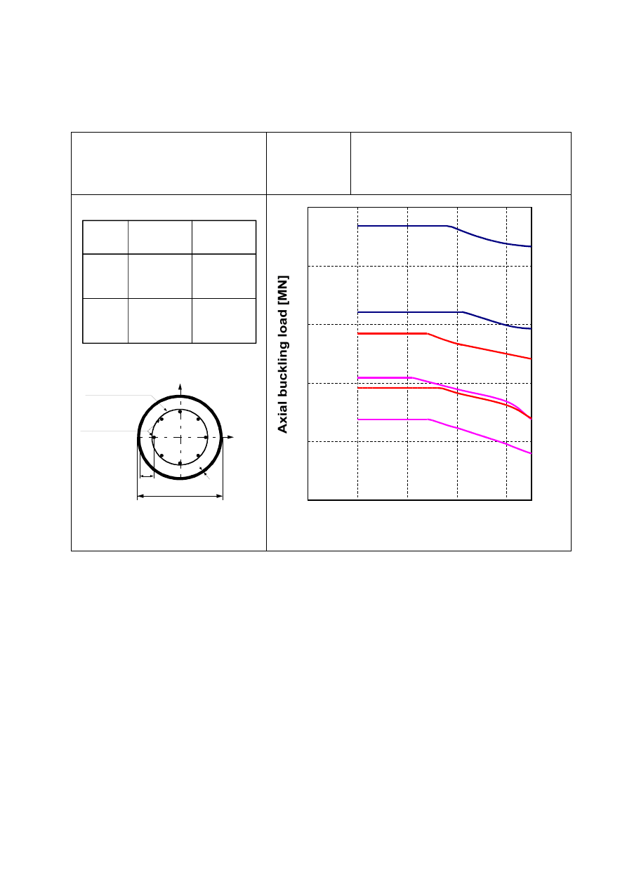
Page 95
Draft prEN1994-1-2:2003
Standard Fire
resistance
R60
Structural Steel Grade :
Concrete Grade :
Reinforcing Bars :
Reinforcement axis distance u
s
:
S 355
C30/35
S 500
40 mm
reinforcing
bars (A )
s
u
s
d
e
Y
Z
concrete (A )
c
curve
Design
section
Circular
A / (A + A )
s
c
s
%
1
2
3
291,1 x 4,5
329,9 x 5,6
406,4 x 6,3
1,0
1,0
1,0
4
5
6
4,0
4,0
4,0
291,1 x 4,5
329,9 x 5,6
406,4 x 6,3
4
1
2
3
4
5
1
1
2
3
4
buckling length [m]
2
6
3
5
4,5
Figure F.3: Design graph for CIRCULAR HOLLOW SECTIONS (R60)
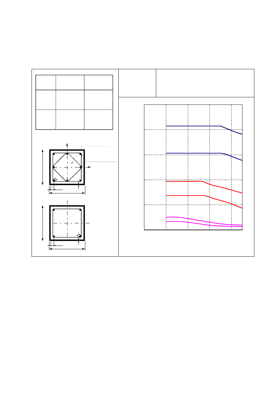
Page 96
Draft prEN1994-1-2:2003
Standard Fire
resistance
R90
Structural Steel Grade :
Concrete Grade :
Reinforcing Bars :
Reinforcement axis distance u
s
:
S 355
C30/35
S 500
40 mm
reinforcing
bars (A )
s
u
s
e
Z
Y
b
concrete (A )
c
h=b
u
s
e
b
h=b
curve
Design
section
Square
A / (A + A )
s
c
s
%
1
2
3
200 x 6,3
300 x 7,1
400 x 10
1,0
1,0
1,0
4
5
6
4,0
4,0
4,0
200 x 6,3
300 x 7,1
400 x 10
1
2
3
4
5
1
2
3
4
Buckling length [m]
1
4
2
3
5
6
4,5
Axial buckling load [MN]
Figure F.4: Design graph for SQUARE HOLLOW SECTIONS (R90)

Page 97
Draft prEN1994-1-2:2003
Annex G
[informative]
Planning and evaluation of experimental models
G.1 Introduction
(1) Test results may be used to assess the fire behaviour of structural members, sub-assemblies or entire
structures if they come from tests adequately performed.
(2) Tests may consider one of the possible thermal actions of section 3, of EN 1991-1-2.
(3) Test results may lead to a global assessment of the fire resistance of a structure or a part of it.
(4) Tests may take into account the heating conditions occuring in a fire and the adequate mechanical
actions. The result is the time during which the structure maintains its resistance to the combined action
of fire and static loads.
(5) Test results may lead to more accurate partial information concerning one or several stages of the
aforementioned calculation models.
(6) Partial information may concern the thermal insulation of a slab, the field of temperature in a section,
or the kind of failure of a structural element.
(7) Tests may only be carried out after a minimum of 5 months following concreting.
G.2 Test for global assessment
(1) The design of the tested specimen and the mechanical actions applied may reflect the conditions of
use.
(2) Tests carried out on the basis of the conventional fire according to CEN standards may be considered
to fulfil the aforementioned rule.
(3) The obtained results may only be used for the specific conditions of the test and, if any, for the field of
application agreed by CEN standards.
G.3 Test for partial information
(1) The tested specimen may be designed according to the kind of partial information expected.
(2) Testing conditions may differ from the conditions of use of the structural member, if this has no
influence on the partial information to be obtained.
(3) The use of the partial information obtained by testing is limited to the same relevant parameters as
those studied during the test.
(4) Regarding heat transfer, results are valid for the same size of the element cross section and the same
heating conditions.
(5) Regarding failure mechanism, results are valid for the same design of the structure, or part of it, the
same boundary conditions and the same levels of loading.
(6) Test results obtained according to the aforementioned rules may be used to replace the appropriate
information given by the calculation models of 4.2, 4.3 and 4.4.
Document Outline
- 4.3.4.1.1 General
- 4.3.4.1.2 Bending resistance of cross-sections of beams
- 4.3.4.1.3 Vertical shear resistance of cross-sections of beams
- 4.3.4.1.4Combined bending and vertical shear
- 4.3.4.1.5Longitudinal Shear Resistance
- 4.3.4.2.1 General
- 4.3.4.2.2 Heating of the cross-section
- 4.3.4.2.3 Structural behaviour - critical temperature model
- 4.3.4.2.4Structural behaviour - bending moment resistance model
- 4.3.4.2.5Verification of shear resistance of stud connectors
- 4.3.4.3.1General
- 4.3.4.3.2 Structural behaviour
- 4.3.4.3.3 Sagging moment resistance Mfi,Rd+
- 4.3.4.3.4 Hogging moment resistance Mfi,Rd -
Wyszukiwarka
Podobne podstrony:
Eurocode 3 Part1 5 (ENG) prEN 1993 1 5 (2003 Set)
Eurocode 3 Part 1 11 Pren 1993 1 11 (Eng)
Eurocode 3 Part 1,10 prEN 1993 1 10 2003
Eurocode 4 Part 1,1 prEN 1994 1 1 2004
Eurocode 1 Part 1,3 prEN 1991 1 3 2003
Eurocode 8 Part 4 prEN 1998 4 2003 (12 2003)
Eurocode 1 Part 1,5 prEN 1991 1 5 2003
Eurocode 1 Part 1,7 prEN 1991 1 7 2003
Eurocode 3 Part 1,9 PrEN 1993 1 9 2003
Eurocode 3 Part 1,8 prEN 1993 1 8 2003
Eurocode 3 Part 1 11 Pren 1993 1 11 (Eng)
Eurocode 3 Part 1,10 prEN 1993 1 10 2003
Eurocode 3 3 Pren 1993 3 (2002 Mai)
Eurocode 3 Part 1,9 PrEN 1993 1 9 2003
Eurocode 3 Part 1,8 prEN 1993 1 8 2003
OLDSMOBILE SILHOUETTE 1994 2003
Eurocode 7 Part 1 DDENV 1997 1 1994
więcej podobnych podstron