
Pathfinder Solutions
N
S
W
E
web: www.pathfindersol.com
90 Oak Point Wrentham, Massachusetts 02093 U.S.A
voice: +01 508-384-1392
fax: +01 508-384-7906
Model-Based Software Engineering
An Overview of Rigorous and Effective Software
Development using UML
version 1.5
February 9, 2000
Copyright 1998-2000 Pathfinder Solutions all right reserved.

Pathfinder Solutions
N
S
W
E
web: www.pathfindersol.com
1
INTRODUCTION
This document provides a brief overview of Model -Based Software Engineerin g (MBSE), an effective
method for developing high performance real -time, embedded, and other types of challenging software
applications. This approach applies a disciplined object -oriented Analysis and pattern -based
translational Design approach with the Unified Modeling Language, the standard object -oriented
modeling notation of the Object Management Group (OMG). The goal of this approach is to significantly
increase software development effectiveness through a rigorous and complete engineering process.
The
most important benefits of this approach include:
n improved software quality
n lower maintenance costs and longer system life
n faster application run -time performance
n increased developer productivity
HISTORY
A software development method is consists o f a process and a notation. The process defines the
techniques for developing the work products of the method. The notation defines a common language
for representing the work products.
OOA/RD
The Shlaer -Mellor Object Oriented Analysis and Recursive Des ign (OOA/RD) process is the most mature
and refined of all object -based methods and is widely accepted by the real -time and embedded
community. The two most important features of the method, separation of analysis from design and the
rigorous partitioning of the application into separate subject -matter domains afford significant benefits to
software development.
UML
The Unified Modeling Language
, a modeling notation with a wide range of elements and numerous
extension facilities, is designed to support a variety of analysis and design methods. This notation enjoys
a wide range of acceptance today and is emerging as the new standard for OO modeling.
MBSE
The Model Based Software Engineering method outlined in this document applies the OOA/RD process
using the UML
graphical notation. The powerful combination of the rigor and maturity of the OOA/RD
process with the familiarity of the standard UML
notation gives the software developer the best
combination of process and notation.

Pathfinder Solutions
N
S
W
E
web: www.pathfindersol.com
2
PROCESS
There are two si gnificant distinctions between MBSE and traditional coding practices:
n separation of analysis from design
n partitioning of the application into separate subject -matter domains
These distinctions help MBSE practitioners realize the benefits of a disciplined software engineering
practice:
n increased developer productivity
n better software quality
n greater system longevity
n higher system performance
n more control and predictability in the software development process
Analysis
Analysis is an expression of the soluti on of a problem in terms of the problem itself. Analysis defines
what the system needs to do, but not how the system will do it. Analysis is application specific, and
virtually free of implementation details. In MBSE, analysis is rigorous, complete, and
free of system
design information.
Design
Design is a strategy for mapping analysis to implementation. Because of the rigor and completeness of
MBSE analysis, design is virtually free of application -specific elements, and instead focuses exclusively
on execution -specific requirements. The primary elements of an MBSE design include a policy
document defining the overall design strategy, a set of foundation base mechanisms, and a set of code
templates. A translation tool uses the design -specific code te mplates to generate complete, deliverable
code from application -specific models. This translation process supports:
n higher software quality through a uniformly applied design
n elimination of hand -coding errors
n increased application performance through unif orm and configurable design optimizations
n reduced integration and debugging effort through the configurable injection of object -level
instrumentation and debug support
Goals
The goals of this process are to:
n apply model -based software engineering in a con sistent manner, leading to higher quality
models and deliverable software
n reduce the overall software engineering development time
n position the developed software to readily respond to future product requirements
n significantly decrease the effort to produ ce and improve the quality and effectiveness of
software engineering documentation
Pathfinder Solutions
N
S
W
E
web: www.pathfindersol.com
3
Development Steps
The overall software development process is broken into four major phases:
n Domain Separation: partition the entire system at the highest level into domain
s of separate
subject matter.
n Domain Development: model each analyzed domain and import each realized (non
-analyzed)
domain developed by hand -coding or generated from other environments (like a GUI/RAD
facility)
n Design: develop a strategy for mapping analy sis to an implementation and for assembling
system components. Design development and preliminary validation is parallel to and
independent from the analysis conducted during Domain Development and is often available
commercially.
n Integration: assemble al l system components and verify that they work together using a
controlled set of iterative development cycles
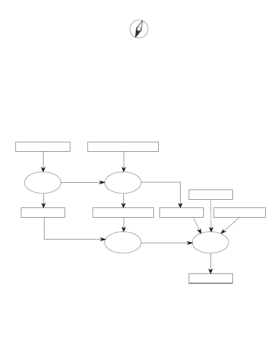
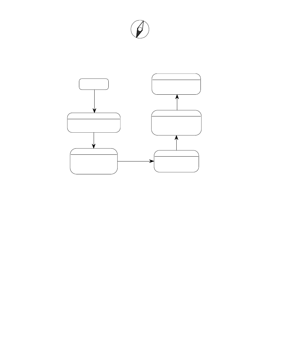
Please refer to figure 1 for the high -level flow of a single build iteration of this process.
Design
Build
Translation
Analysis
Execution-Specific Requirements
Design Pattern Templates
Application-Specific Rqts
implementation libraries
realized elements
Deliverable System
Base Mechanisms
Analysis models
implementation
of models
application-specific and
capacity requirements
figure 1
terms from figure 1:
Analysis ................................ .. the pro cess of developing UML Analysis Models and their Dynamic
Verification, for each analyzed domain in the system. This typically is
conducted largely in parallel with Design.

Pathfinder Solutions
N
S
W
E
web: www.pathfindersol.com
4
Analysis Models ...................... a complete set of UML Analysis, including the Domain Model (for th e
entire system), and for each analyzed domain an Information Model,
Scenario Models, State Models, and Action Models
Application -Specific Requirements
all requirements that define the system under development in
terms of features, specific capabilities, a nd all aspects of system
operation and behavior that are not exclusively Execution
-Specific
Base Mechanisms .................. the set of C++ base and utility classes that provide the operating
infrastructure of the system, including event queueing and dispatch,
inter-task and inter -process communication, basic analysis operation
support, memory management, and general software primitives such as
lists and strings.
Build ................................ ....... the process of compiling and linking the translated implementation code,
realized code and implementatio n libraries into the Deliverable System
Deliverable System ................ the set of executable elements that constitute the software product to be
verified and/or delivered
Design ................................ .... the process of defining and deploying a strategy for deriving an
implementing from the A nalysis, including Structural Architecture,
Design Templates, and Base Mechanisms. This typically is conducted
largely in parallel with Analysis.
Design Policies ....................... a set of Design Patterns that define how the C++ implementation code
for the Analysis will be translated from the Analysis models. These are
captured as template files in the specific notation of the Pathfinder
Solutions Springboard translation engine.
Execution -Specific Requirements
all requirements that define how the system under development
will execute in its specific deployment environment, including task and
processor topology and allocation, general capacities, performance,
operating system interfaces, and application -independent capabilities
realized elements ................... system components that have not been analyzed, and are typically
hand-written code, generated from a specific environment (like a GUI
builder or math algorithm environment), or purchased from a third party
implementation libraries .......... realized system components supporting a specific com piler, language or
operating system environment
Translation .............................. the process of executing the Springboard translation engine to generate
the complete implementation code for all Analysis Models
Domain Separation
The separation of a system into separate subjec t matter domains is the most powerful technique in
MBSE. Proper separation of subject matter supports powerful and simple constructs within domains,
minimizes the complexity of interaction between domains, and facilitates large
-scale reuse. The domain
is a component, the unit of reuse.
The domain chart is a diagram of all software components in the system separated into
domains. These
domains are directionally connected with bridges showing the flow of requirements from the higher level
domains to subord inates that provide required lower -level services. The domain model is a domain chart
with descriptions for all domains and bridges.
The domain chart for a system represents the capabilities of the target system to be delivered in a major
product releas e cycle. Although the domain chart is complete very early in the lifecycle for the release,

Pathfinder Solutions
N
S
W
E
web: www.pathfindersol.com
5
the models within the domains mature with each step of integration. For earlier iterative builds within a
release, individual domains may not be complete, but at
the end of the release, all abstracted domains
should be mature. As the project moves from one release to the next, the domain model is modified to
consider new subject matter areas as necessary.
Domain Modeling Goals
n identify the boundaries of the syste m under construction
n identify the separate subject matters in the system
n partition the system into manageable components
n identify which subject matters you will analyze, realize (hand code) or otherwise generate, and
buy
n establish a flow of requirements fr om domains containing higher -level abstractions down to
lower-level domains
Domain Development
To manage the complexity of analysis and integration, domain development for a product release is
partitioned into several iterative build steps. Each build sh ould span about 3 months. Distribute release
functionality evenly across builds.
The analysis of an individual domain is a rigorous process that is driven by requirements allocated to the
domain within the context of a single iterative build. The Domain
Requirements Matrix is a table of
requirement references for a single domain in a single build. This lightweight document is used to track
all system -level and bridge requirements levied on a domain. Knowing the specific requirements that a
domain must s atisfy gives the analyst a clear direction when creating models for the domain.
Information Modeling
The development of each domain begins by identifying the classes that populate the domain.
Descriptive attributes are added to each class and classes are related with associations, and inheritance
hierarchies. Information Modeling defines the domain from the perspective of data.
Scenario Modeling
Once the data abstractions have been constructed, a strategy for inter -class communication is developed
on a scenario basis. Event, creation, and deletion activity between the domain's bridge interface,
classes and server domains are laid out in a sequential manner following a limited set of key scenarios.
State and Service Modeling
The strategy developed in the Scenario Modeling phase is broken out among the states of active
classes, class-based services (methods), and domain -based services. Events are defined, and detailed
behavior for all scenarios is defined. The actions for each state and service are s
ummarized.
Action Modeling
The complete and rigorous specification of each state action, class -based service, and domain -based
service is expressed at the level of analysis in the Action Language. This textual language supports a
convenient, complete set of analysis processing primitives, and enforces the separation of Analysis from
Implementation.

Pathfinder Solutions
N
S
W
E
web: www.pathfindersol.com
6
Dynamic Verification
During Dynamic Verification the models are executed to verify their correctness. The analysis is
translated into code that runs in an in strumented executable. The flow of control within the domain, and
the run-time values of analysis data elements (attribute, event parameters, service parameters, and
variables) are examined and verified. The patterns of communication laid down during Sce
nario
Modeling are followed through each scenario.
Integration
Integration can begin once the domains have been verified and any realized domains are complete.
Submissions from domain developers are assembled in a careful, stepwise process.
The Software I ntegration Phase focuses on the system elements that can be run (or simulated) on the
development platform. The components of the system are assembled, and the system is verified to the
greatest extent possible without running on the target hardware. Thi s effort is focused to illuminate all
problems possible in the relative luxury of the development environment.
The Hardware Integration Phase takes the system to the target platform, where the final, hardware
-
specific verification is done. The flexibility of code templates facilitates the injection of select
instrumentation and execution control code into the target system, supporting object
-level debugging
there.
The overall integration cycle from Dynamic Verification through Software Integration and fin
ally onto the
target platform is repeated in its entirety for each iterative build in the release.
Pathfinder Solutions
N
S
W
E
web: www.pathfindersol.com
7
ANALYSIS WITH UML
The full range of primitives in UML
is quite wide. UML
diagrams can be created from a number of
perspectives including Conceptual, Specification, and Implementation. Analysis in MBSE is performed
from the UML
Conceptual perspective, and is expressed through the following subset of UML
.
Domain Model
System
The system is expressed through a domain chart where every software requirement
of the system is
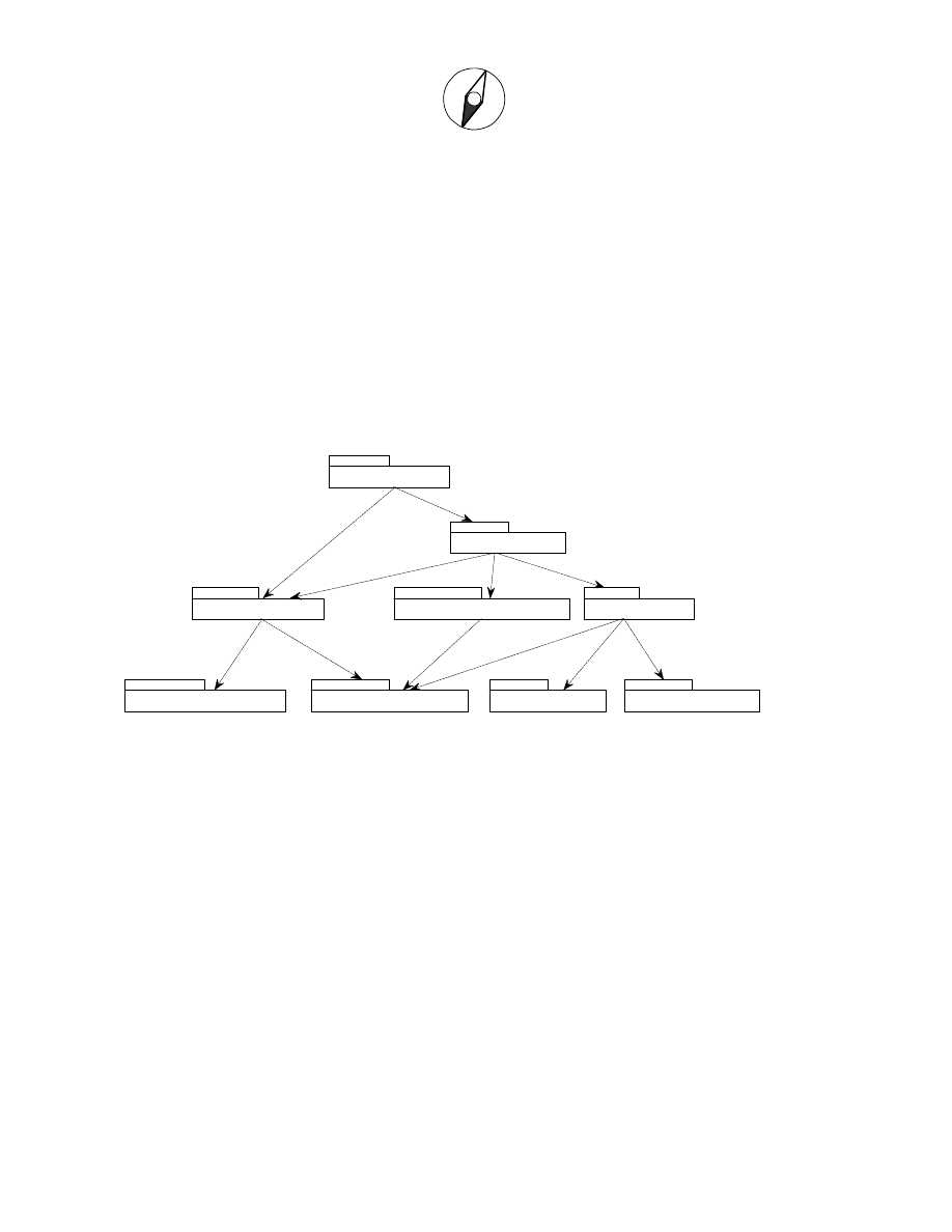
assigned to a component, or domain. A Class Diagram with Packages and Dependencies represents the
domain chart. Please see figure 2.
NetworkCommunication
(NCOM)
GraphicalUserInterface
(GUI)
SoftwareMechanisms
(SW)
BeamManagement
(BM)
OperatorInterface
(OI)
AirTrafficControl
(ATC)
AntennaControl
(ANTC)
AircraftTracking
(AT)
RadarTargeting
(RT)
figure 2 - the domain chart Class Diagram
Domain
The domain is abstracted using the Package, capturi ng its name, description, prefix, a list of domain -
specific types, and a list of services. Each service has a name, and a set of parameters. Each service
parameter has a name, a data type, a description and an I/O mode. Please note the Package symbols i
n
figure 2. Domains at a higher level of abstraction are shown nearer the top.
Bridge
The bridge shows the flow of requirements from more abstract to lower levels. Please note the
Dependency arrows in figure 2.
Pathfinder Solutions
N
S
W
E
web: www.pathfindersol.com
8
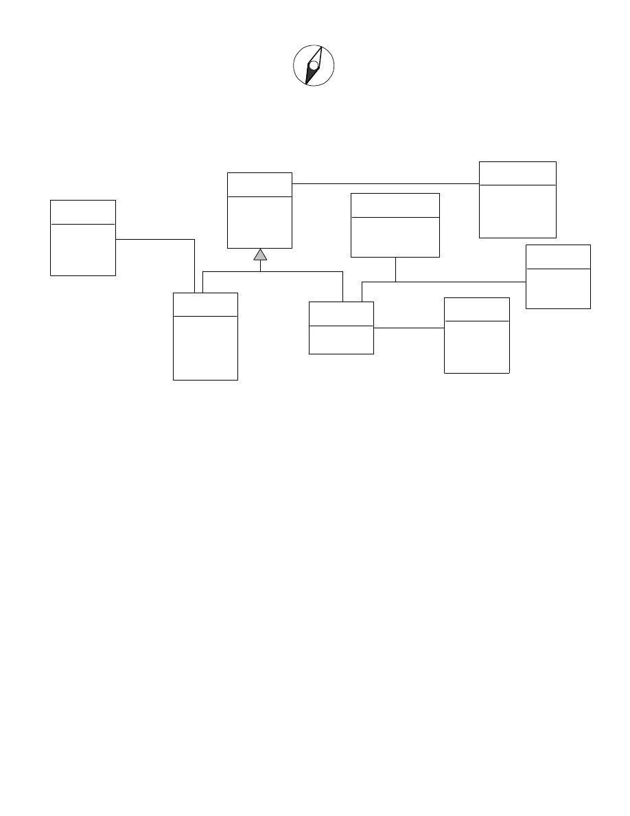
Information Model
The information model is e xpressed with a Class Diagram. Please refer to figure 3.
Airline
(AL)
name
emergencyContact
normalContact
AircraftInFlight
(ACF)
altitude
latitude
longitude
priority
GateAssignment
(GAS)
timeAssigned
expectedReleaseTime
Aircraft
(AC)
tailNumber
type
fuelStatus
AirportZone
(AZ)
innerRange
outerRange
altitudeCap
Taxiway
(TW)
number
length
availabilityStatus
Gate
(GA)
number
terminal
TaxiingAircraft
(ACT)
gateAssignment
0..1
0..1
A5
assignee
destination
0..*
0..1
A3
traffic
location
1..*
1
A2
fleet
owner
1
0..*
A1
location
traffic
S4
S4
figure 3: the information model Class Diagram
Object
The object is abstracted using the Class, capturing its name, description, prefix, a list of attributes, and a
list of services. Each attribute has a name, a data type, and a description. Each service has a name, an
indication of whether the service is instance -based or object -based, and a set of parameters. Each
service parameter has a name, a data type, a description, and an I/O mode. Please
note the Class
symbols in figure 3.
Inheritance Relationship
A supertype Class abstracts the common attributes, relationships, and behavior of its subtype Classes.
This form of relationship is shown with a set of Inheritance arrows, one for each subtype pointing to the
common supertype. All arrows pointing to the same supertype have the same relationship identifier.
Please note the S4 Generalization arrows that relate the supertype Aircraft to its subtypes AircraftInFlight
and TaxiingAircraft.
Association
An Association arrow abstracts the binary relationship – an association between two Classes, or with one
Class to itself. The Association has a shorthand identifier (of the form "A<number>"), a description, and
participant information at each end. Fo r each participant, there is a role phrase, multiplicity (how many),
and conditionality. Please note the Association lines in figure 3.
Associative Object
Sometimes a binary relationship has its own data characteristics which are abstracted in an associat
ive
object, captured as a Class connected to an Association arrow. Please note the GateAssignment Class
connected to Association R5 in figure 3.
Pathfinder Solutions
N
S
W
E
web: www.pathfindersol.com
9
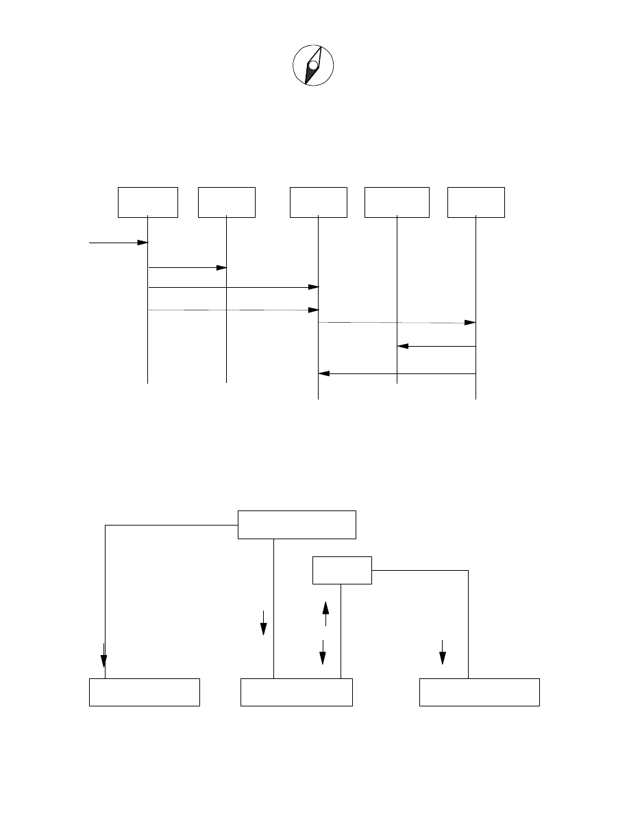
Scenario Model
The pattern of communication between services and state models within a domain can be captured
two
different ways with UML
diagrams. The Sequence Diagram is used to create a table of the domains
and objects in a scenario and sequentially list the events, Class instance creations and deletions that
occur on a scenario basis. Please refer to figure 4.
TaxiingAircraft
Airline
AircraftTracking
GateAssignment
AircraftInFlight
ACT:AssignTaxiway
ACT:GateAvailable
Create
AL:GateRequested
Create
Delete
AT:AircraftLanded
figure 4: Sequence Diagram
Sometimes it is helpful to consider the OCM for a scenario in the context of a topological layout of the
Classes for a domain, to imply relative capabilities/intelligence and responsibilities. In this case the
Collaborati on Diagram is used instead of the simple tabular approach of the Sequence Diagram. These
perspectives are interchangeable, and many CASE tools support automatic updates between
perspectives. Please refer to figure 5.
GateAssignment:Definition
AircraftTracking:Definition
TaxiingAircraft:Definition
AircraftInFlight:Definition
Airline
2: Delete
4: ACT:AssignTaxiway
3: Create
5: AL:GateRequested
7: ACT:GateAvailable
6: Create
figure 5: Collaboration Diagram
Pathfinder Solutions
N
S
W
E
web: www.pathfindersol.com
10
State Model
State dependent behavior of a class forms its lifecycle. The UML
State Model is used to capture these
lifecycles in terms of states, events, transitions, superstates and substates. Please refer to figure 6.
TaxiingOut
link to allocated taxiway
unlink gate
request takeoff clearance
HeadingToGate
link with allocated gate
proceed to gate
TaxiingIn
link to assigned taxiway
generate AL:GateRequested
TakingOff
unlink taxiway
convert self to AircraftInFlight
ParkedAtGate
unlink taxiway
initiate arrival servicing
Landed
ACT:TakeoffClearanceGranted(runway)
ACT:ReadyToDepart(taxiway)
ACT:AssignTaxiway(taxiway)
ACT:GateAvailable(gate)
ACT:ArrivedAtGate()
Figure 6: State Diagram
State
The State symbol is used to abstract a single stage in the lifecycle of the object. Please refer to the
State symbols in figure 6.
Event
Events are defined on the State Diagram and are associated with Transitions from one State to another.
Please refer to the Events and their associated Transition arrows in figure 6.
Action Model
The Action Model is a detailed specification of a state action or service action at the level of analysis.
Action Language is used to abstract analysis -level processing primitives, and enforce the separation of
analysis from implementation. The Action Language statements for an action are captured in a textual
container associated with the action. The Action Model below captures the detailed behavior for the
TaxiingOut state in Fig ure 6 above.
// State action for ACT.TaxiingOut
Ref<Gate> my_gate;
// link to allocated taxiway
LINK this A3 taxiway;
// unlink gate
my_gate = Find this->A5;
UNLINK this A5 my_gate;
this.gateAssignment = NO_GATE;

Pathfinder Solutions
N
S
W
E
web: www.pathfindersol.com
11
// request takeoff clearance
ATC:RequestTakeoffClearance (this.tailNumber)

Pathfinder Solutions
N
S
W
E
web: www.pathfindersol.com
12
REFERENCES
For more information on Model Based Software Engineering, please call Pathfinder Solutions at 888
-
OOA-PATH (888-662-7248) or +01-508-384-1392, email us at info@pathfindersol.com, or visit us at
www.pathfinde rsol.com.
You may wish to refer to the following sources:
on the UML
:
"The Unified Modeling Language User Guide ", Grady Booch, James Rumbaugh, Ivar Jacobson,
Addison Wesley, 1999; ISBN 0 -201-57168-4
"UML Distilled ", Martin Fowler, Addison Wesley, 1997 ; ISBN 0-201-32563-2
"UML Summary Version 1.1", Object Management Group, Inc. 1997 (this paper is available from
www.omg.org)
on OOA/RD:
"Object Lifecycles ", Sally Shlaer and Stephen Mellor, Prentice -Hall, 1992; ISBN 0 -13-629940-7
UML
is a trademark of Object Management Group, Inc in the U.S. and other countries.
Wyszukiwarka
Podobne podstrony:
MBSE, ooarev
MBSE, ooaeng
MBSE, popkin
MBSE, arch ag
MBSE, dv guide
MBSE, model conventions
MBSE, AL oview
MBSE Sprng ug id 770850 Nieznany
MBSE, ooarev
chlamydiofiloza bo i ov
ov calendar m
ov straddles h
ov covered
chlamydiofiloza bo i ov
chor grucz mlek u Ov i kóz
więcej podobnych podstron