Alarm connection instruction
The DVR support two alarm input mode(normal on/off),these
two mode has the same external connection method but different
setting in host system. Choosing normal on/off mode by software
operation make it simple to user and below are the detail steps of
normal on mode setting.
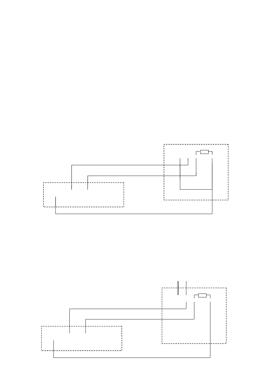
1. Alarm external connection
Typical connection:the DVR host supply power to sensor.
We suggest sensor get power supply separately to avoid power supply
instability if there has a long distance between DVR and sensor. We suggest
connected both side GND together to stable the power supply as follows:
DVR
Probe
Probe
+12V
GND
IN 1
IN 2
+
-
NO
C
+
-
NO
C
DVR
+12V
GND
IN 1
IN 2
+12V
Probe
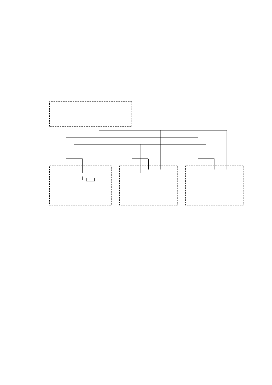
If user wants to parallel connected multi-sensor to host, the DVR can’t
recognize the triggered sensor. User needs to parallel connect this resistance
to all sensors as below fig.
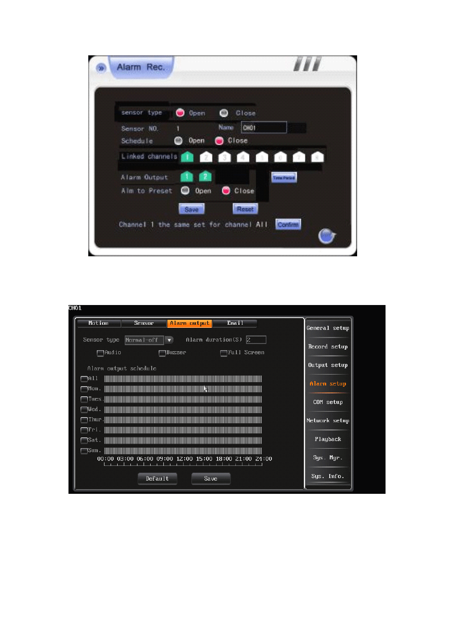
2. Alarm input normal on/off setting of software
7000T series: Enter main interface —> record mode—> alarm record to
enter the interface as follows, and choose the open status of sensor type.
DVR
Probe 1
+12V
GND
IN 1
IN 2
+
-
C
NO
Probe 3
+
-
C
NO
Probe 2
+
-
C
NO
8000T/8200T series: Enter the main interface->alarm setup-> alarm
output ,and choose the normal on status of sensor type.
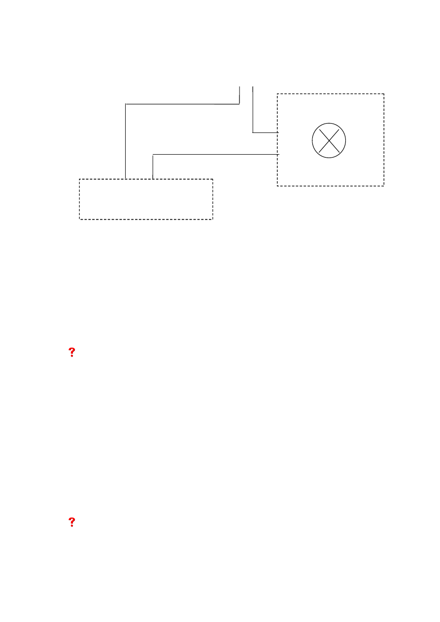
3. Alarm output connection
When alarm happens, the main board will give a triggered voltage signal
to the alarm output equipment(loud speaker, light, etc) and make them output
alarm. But the alarm equipment should has a separately power supply.
There has an power consumption limit of external alarm equipment:
7000T series:240V/AC 7A, 125V/AC 10A, 28V/DC 10A
8000T/8200T series:120V/AC 1A, 24V/DC 1A
The
The
The
The excessive
excessive
excessive
excessive power
power
power
power consumption
consumption
consumption
consumption may
may
may
may damage
damage
damage
damage main
main
main
main board.
board.
board.
board.
FAQ
FAQ
FAQ
FAQ
01:How to use the alarm function?
Answer : Our system supports general sensors. (e.g. smoke sensor, IR
sensor ) Outgoing On/off value transfers the signal to Server via alarm
processing module. And it can enable related recording or output the
On/Off value , all our products support normal open and normal close
working modes
①In case your sensor equipments are of high power consumption, to
avoid damaging the alarm output module, please make relay extension
connection.
②In case you are using high frequency equipments, e.g. High frequency
lights please make relay extension connection method, or alarm module
may not work properly.
02:How to clear alarm?
Answer: you can clear the alarms by pressing the “alarm clear” key on the
IR remote controller. If the host DVR is locked, please login first.
DVR
OUT 1A
OUT 1B
Independent power supply
Alarm Speaker
Wyszukiwarka
Podobne podstrony:
2 3 2 5 Packet Tracer Implementing?sic Connectivity Instructions
casio vibrating alarm watch instructions
4 2 4 5 Packet Tracer Connecting a Wired and Wireless LAN Instructions
Instrukcja obsługi alarm Logic CAN LC 5 wyd 1 (2)
Instrukcja obsługi Nokia Connection Manager PL
Blaupunkt CR5WH Alarm Clock Radio instrukcja EN i PL
6 4 3 3 Packet Tracer Connect a Router to a LAN Instructions
11 3 2 2 Packet Tracer Test Connectivity with Traceroute Instructions
Instrukcja obsługi alarm Logic CAN LC4
Instrukcja obslugi Connectify, informatyka
instrukcja APS 150MX, A U T O Alarm, instrukcje użytkowania
instrukcja APS400MX, A U T O Alarm, instrukcje użytkowania
instrukcja APS150MXA, A U T O Alarm, instrukcje użytkowania
Instrukcja Alarm Prestige APS 150MX
instrukcja alarm 486
Instruction of connection and programming of OSCAR N PLUS OBDCAN controller
instrukcja alarm bx2000
Instrukcja alarm yaris
więcej podobnych podstron