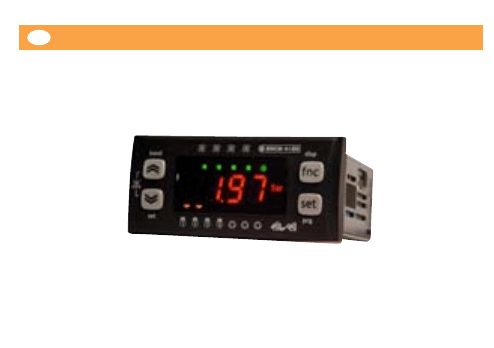
EWCM 4120-4150-4180
EN
e
Compact controller for compressor plants
1

2
Summary
INTRODUCTION - CHaracteristics ............................................................................................................................................................4
CONDITIONS OF USE...................................................................................................................................................................................4
MECHANICAL ASSEMBLY............................................................................................................................................................................7
WIRING DIAGRAMS......................................................................................................................................................................................7
CONNECTION DIFFERENCES BETWEEN EWCM412/415/418 and EWCM4120/4150/4180 .......................................................13
BASIC FUNCTIONS .....................................................................................................................................................................................14
LEDs........................................................................................................................................................................................................14
Displays in particular states..............................................................................................................................................................15
Keys........................................................................................................................................................................................................16
User interface configuration............................................................................................................................................................17
Main display.........................................................................................................................................................................................19
Password and visibility.......................................................................................................................................................................19
Accessing and using the menus......................................................................................................................................................20
Machine state menu ..........................................................................................................................................................................20
Programming menu ...........................................................................................................................................................................21
CONFIGURING THE MACHINE.................................................................................................................................................................21
1) ANALOGUE INPUTS (AI3, AI4)....................................................................................................................................................21
3) HIGH/LOW VOLTAGE DIGITAL OUTPUTS (DO1…DO6)........................................................................................................25
4) PWM/OPEN COLLECTOR OUTPUTS AO1 AND AO2 .............................................................................................................26
5) TRIAC TC OUTPUT.........................................................................................................................................................................29
6) LOW VOLTAGE ANALOGUE AO3 OUTPUT .............................................................................................................................30

3
COMPRESSOR CONTROL..........................................................................................................................................................................31
Inverter compressor control............................................................................................................................................................32
Digital compressor control...............................................................................................................................................................34
Compressor timing.............................................................................................................................................................................36
Power stages........................................................................................................................................................................................37
Compressor switch-on policies .......................................................................................................................................................37
CONDENSATION CONTROL.....................................................................................................................................................................39
INVERTER COMPRESSOR CONTROL ..............................................................................................................................................40
DIGITAL FAN CONTROL....................................................................................................................................................................44
ADVANCED FUNCTIONS...........................................................................................................................................................................49
On/off device ......................................................................................................................................................................................49
Recording operating hours ..............................................................................................................................................................50
Real Time Clock (RTC).......................................................................................................................................................................50
ALARMS ........................................................................................................................................................................................................51
Alarms list with description and activation parameters............................................................................................................53
Alarm list with actions and notes...................................................................................................................................................55
Alarms log ............................................................................................................................................................................................58
SERIAL CONFIGURATION..........................................................................................................................................................................59
PARAMETERS LIST ......................................................................................................................................................................................61
NAVIGATION MENU DIAGRAMS............................................................................................................................................................69
ACCESSORY PRODUCTS............................................................................................................................................................................72
TECHNICAL DATA.......................................................................................................................................................................................73
Mechanical characteristics ...............................................................................................................................................................73
Electrical characteristics....................................................................................................................................................................73
Input/Output characteristics............................................................................................................................................................73

4
INTRODUCTION - CHARACTERISTICS
The EWCM is a device which represents a family of controllers dedicated to managing the production room of a
refrigerator plant:
Configurable user interface.
Configurable navigation menu.
Alarms log.
Temperature control via inlet probe depending on configuration and installation.
Condensation control via outlet probe depending on configuration and installation.
NTC, 4…20 mA, 0…5V or 0.10V parameter-configurable inputs.
Parameter settings via keyboard or PC.
Copy card for uploading and downloading parameter maps.
Control of a single circuit with up to 4 compressors (or combination of compressors) whole or segmented with
up to 4 power stages/inverter compressor.
Condensation control with inverter fan or up to 4 digital fans.
CONDITIONS OF USE
Permitted use
This device is intended for controlling compressor plants.
For safety reasons, the instrument must be installed and used according to the instructions provided and in particular,
under normal conditions, parts bearing dangerous voltages must not be accessible. The device must be adequately
protected from water and dust as per the application, and must also only be accessible via the use of tools (with the
exception of the frontlet).
The device is ideally suited for use in household appliances and/or similar refrigeration equipment and has been
tested with regard to the aspects concerning European reference standards on safety. It is classified as follows:

5
according to its manufacture: as an independently mounted or integrated automatic electronic control device
to be incorporated;
according to its automatic operating features, as a 1 B-type operated control type;
as a Class A device in relation to the category and structure of the software;
as a device with pollution grade 2;
as a device with class D fire resistance;
overvoltage category grade II
as a device made with class IIIa material.
Uses not permitted
Any use other than that expressly permitted is prohibited.
The relay contacts supplied are of the functional type and subject to fault (since they are electronically controlled
they are prone to short-circuit or remaining open): any protection devices specified in product standards or suggested
by common sense for obvious safety requirements must be installed externally to the instrument.
RESIDUAL RISKS AND RESPONSIBILITIES
Eliwell is not liable for damage due to:
unspecified installation/use and, in particular, in contravention of the safety requirements of established
legislation or specified in this document;
use on equipment which does not provide adequate protection against electrocution, water and dust in the
actual installation conditions;
use on equipment which allows toolfree access to dangerous components;
tampering with and/or alteration of the products;
installation/use on equipment which does not comply with established legislation and standards.

6
DISCLAIMER
This document is the exclusive property of ELIWELL CONTROLS Srl and shall not be reproduced or distribuited
without authorisation of ELIWELL CONTROLS Srl.
Although great care has been exercised of this document, ELIWELL CONTROLS Srl, its employees or its vendors,
cannot accept any liability whatsoever connected with its use.
The same applies to any person or company involved in preparing and editing this document.
ELIWELL CONTROLS Srl reserves the right to make any changes or improvement without prior notice.
ELECTRICAL WIRING
Attention! Never work on electrical connections when the machine is switched on. The operation must be
carried out by qualified personnel.
To ensure proper connections, comply with the following:
using a power supply which does not correspond to the specifications given, can seriously damage the system;
use cables of suitable section for the terminals used.
Separate, as much as possible, the cables of probes and digital inputs from inductive loads and power
connections to prevent electromagnetic interference. Do not place the probe cables near other electrical
equipment (switches, meters, etc.)
Make connections as short as possible and do not wind them around electrically connected parts.
It is recommended to use screened wires for probe connections.
To avoid causing static discharges, do not touch the electronic components on the boards.
Eliwell supplies the high voltage cables to connect the device to loads, the power supply, probes, digital inputs, etc.
according to p/n - see the Accessories chapter.
The device must be connected to a suitable transformer that complies with the specifications provided in the
Technical Data chapter.
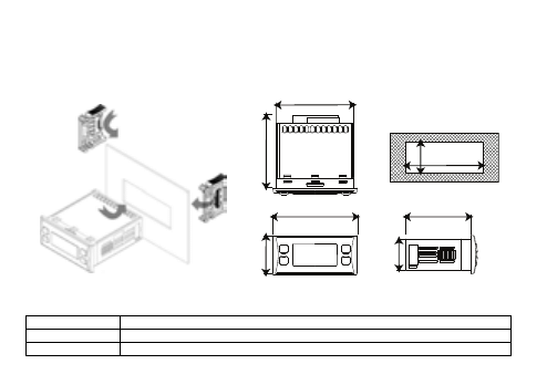
MECHANICAL ASSEMBLY
The instrument is designed for panel mounting. Make a 29x71 mm hole and insert the instrument; secure it with the
special brackets provided. Do not mount the instrument in damp and/or dirt-laden areas; it is suitable for use in
places with ordinary or normal levels of pollution. Keep the area around the instrument cooling slots adequately
ventilated. The TTl serial port is located on the left side of the instrument.
7
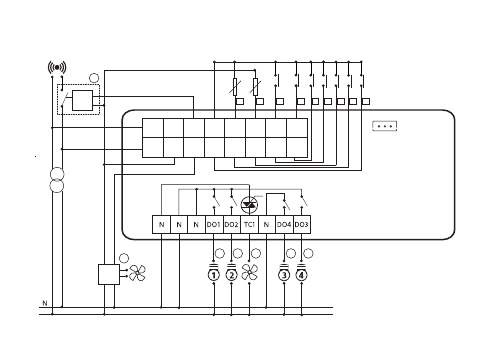
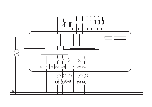
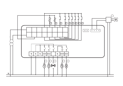
WIRING DIAGRAMS
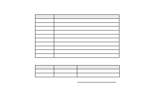
Circuit diagram key
12Va
12Va power supply
5Vc
5Vc power supply for 10A max ratiometric transducer
12Vc
Auxiliary 12Vc power supply for AO1 or DO5 output
76.4mm
76.4mm
70mm
70mm
28mm28mm
35mm35mm
29mm29mm
71mm
71mm
67mm67mm
59mm
59mm

8
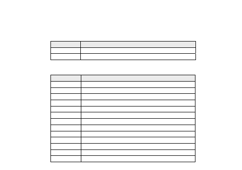
DO1... DO6
2A - 230Va high voltage relay outputs
N
Neutral
TC
TRIAC 2A - 230Va high voltage output
AO1/AO2
PWM/Open collector analogue output for external fan module (to be used with 12Vc)
AO3
0/10 V, 4-20 mA, 0-20 mA low voltage analogue output
DO5
Open collector output (to be used with 12Vc)
DI1...DI5
Digital inputs voltage-free contact (closing current to 0.5mA ground)
AI1 (DI6)..AI2 (DI7) Digital inputs voltage-free contact (closing current to 0.5mA ground)
AI3..AI4
NTC */ voltage, current** / Digital Input configurable analogue inputs***
GND
Ground
TTL (COM 1)
TTL serial for connection to Copy Card/ParamManager/ DeviceManager or Televis
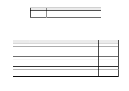
1
Outlet pressure switch ON/OFF (EWCM 4120 and EWCM 4180)
2
Inlet pressure switch ON/OFF
3 … 6
Block compressor 1… 4 ON/OFF
7
Remote ON/OFF
8
Outlet probe (EWCM 4180)
INPUT
9
Inlet probe
10 … 13
Compressor/power step 1_4 ON/OFF
14
TC high voltage condenser fan (EWCM 4120)
15
TC low voltage condenser fan (EWCM 4180)
16
Low voltage ON/OFF alarm (EWCM 4120)
OU
TPU
T
17
ON/OFF alarm (EWCM 4150 and EWCM 4180)
* SEMITEC 103AT type (10LΩ / 25°C).
** 4…20mA current input or 0…5V/0…10V voltage input or voltage-free digital input.
*** voltage-free digital input.
EWCM 4120
L
DO5 GND AI4
AI3
DI7
DI6
12Vac 5Vdc
AO1 DI5
DI4
DI3
DI2
DI1
12Vac 12Vdc
AI2
AI1
16
15
11
10
14
13
12
3
1
4
2
5
6
7
8
9
12 Vdc 35mA max.
Not
used
EWCM 4120
9
EWCM 4150
L
DO5 GND AI4
AI3
DI7
DI6
12Vac 5Vdc
AO1 DI5
DI4
DI3
DI2
DI1
12Vac 12Vdc
AI2
AI1
11
10
17
13
12
3
1
4
2
5
6
7
8
9
DO6
AO3(I)
AO3(V)
GND
AO2
Not
used
EWCM 4150
10
EWCM 4180
L
DO5 GND AI4
AI3
DI7
DI6
12Vac 5Vdc
AO1 DI5
DI4
DI3
DI2
DI1
12Vac 12Vdc
AI2
AI1
15
11
10
17
13
12
3
1
4
2
5
6
7
8
9
DO6
AO3(I)
AO3(V)
GND
AO2
Not
used
EWCM 4180
11
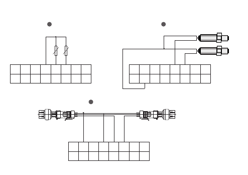
Examples of probe connections
DO5 GND
AI4
AI3 DI7
DI6
12Vac 5Vdc
AO1
DI5
DI4
DI3
DI2
DI1
12Vac 12Vdc
AI2
AI1
DO5 GND
AI4
AI3 DI7
DI6
12Vac 5Vdc
AO1
DI5
DI4
DI3
DI2
DI1
12Vac 12Vdc
AI2
AI1
DO5 GND
AI4
AI3 DI7
DI6
12Vac 5Vdc
AO1
DI5
DI4
DI3
DI2
DI1
12Vac 12Vdc
AI2
AI1
EWPA 4/20mA
NTC
EWPA R 0/5V
12
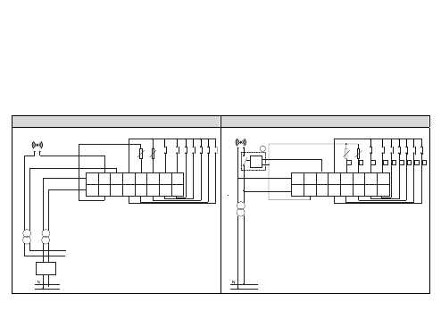
CONNECTION DIFFERENCES BETWEEN EWCM412/415/418 and EWCM4120/4150/4180
The main differences between EWCM412/415/418 and EWCM4120/4150/4180 are listed below:
The terminals of connectors EWCM412/415/418 are different from those of EWCM4120/4150/4180.
The alarm output on EWCM412 (12-24Va max 500mA output for use with 12Va insulated from power supply of
device) is replaced with an open collector output (with parameter configurable function) for use with 12Vc.
PLEASE NOTE: the terminals of the connector, to be used for this output, do not correspond between
EWCM412 and EWCM4120 (see diagram below).
The relays of EWCM4120/4150/4180 do not have a single common contact as on EWCM412/415/418; output
DO4 is separate from the other outputs (DO1, DO2 and DO3)
Connection EWCM412
Connection EWCM4120
L
DO5 GND AI4
AI3
DI7
DI6
12Vac 5Vac
AO1 DI5
DI4
DI3
DI2
DI1
12Vac 12Vdc
AI2
AI1
16
3
1
4
2
5
6
7
8
9
12 Vdc 35mA max.
EWCM 4120
L
GND GND ST2
ST1
ID7
ID6
12Vac ALL
TK1 ID5
ID4
ID3
ID2
ID1
12Vac 12Vdc
A
B
T2
T1
EWCM412
13
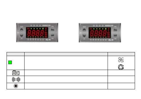
BASIC FUNCTIONS
The user has a display and 4 keys for programming the instrument and checking its status.
When the instrument is powered on for the first time it performs a lamp test, during which time the display and LEDs
flash for several seconds to check that they all function correctly. The instrument has two main menus, the “Machine
state” menu and the “Programming" menu.
EWCM4120 and EWCM4180
EWCM4150
LEDs
Symbol / icon Description
Icon on front panel
(8) … (11)
EWCM4120-EWCM4180
Fan bar (configurable LEDs using parameters UI07…UI10)
EWCM4150
LEDs NOT configured (configurable LEDs using parameters UI07…UI10)
Programming menu
Alarm. If permanently on the alarm is active, if flashing the alarm is
silenced.
Heating. Heating mode
14
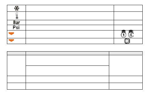
Cooling. Cooling mode
Display of temperature values in °C/°F
Display of pressure values in Bar
Display of pressure values in Psi
(1) ... (4) Compressor ON (LED configurable using parameters UI00…UI03)
-
(5) ... (7) LEDs NOT configured (Led configurable using parameters UI04…UI06)
Displays in particular states
Status
Display
LEDs /icons
Main display alternated with alarm code (if more than one alarm is
present simultaneously, the one with the lower index will be
displayed)
If there is an
alarm
If the measurement on the main display is incorrect, the error code
will be displayed; If a further alarm is present, it will alternate between
“---“ and the error code.
Alarm icon permanently on
If alarm is silenced it will
flash
Remote
ON/OFF
Display "OFF" flashing
All off
ON/OFF
keyboard/local Display "OFF" continuous
All off
15

Keys
set
SET key used to:
SET function: access “machine state" menu.
access menu subfolders.
access parameter value.
Confirm parameter value and/or exit.
prg (Programming menu): press and hold (5 secs) to access the Parameters folders from the
main display.
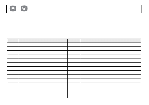
UP key used to:
Scroll down the displayed folders and parameters.
Increase parameter value (if in parameter edit mode).
Band: press and hold (5 sec.) to enter the menu for viewing/editing the compressor plant
adjustment range.
DOWN key used to:
Scroll up the folders and parameters display.
Decrease the parameter value (if in parameter edit mode).
set: Press and hold (5 secs) to access the menu for viewing/editing the setpoint adjustment,
and the type of set point will be displayed. To edit the set point, use the "set" key to display
the value and the "Up" and "Down” keys to edit it.
Press “set” to confirm or “func” to exit (see Note).
FNC key used to:
Menu exit, parameter list, parameter value (without saving value) and return to the previous level.
disp: by holding down for some time (5 secs) access is provided to the menu for selecting the main
display. Using the “up” e “down” keys, only the values that have been configured as present in the
device will be displayed (flashing) and the selection is confirmed by pressing the “set” key.
16
+
If any alarms are present, they can be reset by simultaneously pressing the UP + DOWN
keys.
Press any key to silence the alarms; If there is an alarm, pressing a key once will silence it and will not activate the
corresponding function.
User interface configuration
The LEDs are configured using parameters UI00..UI10:
LED utilities table:
Value Description
ON
Flashing
0
LED disabled
-
-
1 _ 4 Compressor 1… 4
Active Interstep timing
5
Step 2 compressor 1
Active Interstep timing
6
Step 2 compressor 2
Active Interstep timing
7
Step 2 compressor 3
Active Interstep timing
8
Step 3 compressor 1
Active Interstep timing
9
Step 3 compressor 2
Active Interstep timing
10
Step 4 compressor 1
Active Interstep timing
11 …14 Fan 1 ... 4 ON
Active Interstep timing
15
Alarm
Active Silenced
16 … 22 Not used
-
-
23
Compressor inverter enabling
Active -
24
Fan inverter enabling
Active -
25
Inverter fan
Active Interstep timing
17
18
26
Inverter compressors
Active Interstep timing
27
Inverter fan bar ≥25%
Active -
28
Inverter fan bar ≥50%
Active -
29
Inverter fan bar ≥75%
Active -
30
Inverter compressor bar ≥25%
Active -
31
Inverter compressor bar ≥50%
Active -
32
Inverter compressor bar ≥75%
Active -
User interface configuration parameters:
Par. Description
Min Max U.M. Notes
UI12 Select main set point display
0
1
num 0=display Inlet Set
1= display Outlet Set
UI13 Select main display
0
6
num
UI20 Installation password
0
255 num Default UI20= 1
UI21 Manufacturer password
0
255 num Default UI21=2
UI22 Unit of temperature measurement
0
1
num 0=°C, 1=°F
UI23 Unit of pressure measurement
0
1
num 0=Bar, 1=Psi
Parameters UI20 - UI21
In parameters UI20 and UI21 respectively, the installer (level 1) password and manufacturer (level 2) password must
be changed. See PASSWORD AND VISIBILITY chapter.
19
Main display
Under normal operating conditions, it is possible to select which measurement to display on-screen (not in the
navigation menu or in the case of alarms).
Press and hold the “FNC” key to access the folder containing all of the available measurements. The only
measurements which will be displayed, flashing on-screen, are those which can be selected and which are present in
the device (for example The RTC will appear in the list only if it has been configured as present). The list is as follows:
AI01…AI04 (one of the probes available among those configured in the device)
RTC (clock)
Set point; In OFF, the set point displayed is the set point for the previous operating mode in OFF status.
The following procedure describes how to set the main display:
Press the “FNC” key for 5 seconds (value configurable from parameter UI19)
select the measurement to display by scrolling through the various options using the Up and Down keys
press the “set” key
Par. Description
Min
Max U.M. Notes
UI13 Main display
0
6
num
0=analogue input 1, 1=analogue input 2, 2=analogue
input 3, 3=analogue input 4, 4= analogue input 5,
5= clock, 6= set point configured
NOTE: Either the inlet setpoint or the outlet setpoint will be displayed, depending on parameter UI12 (select main set
point display).
Password and visibility
To view parameters visible for the given password, open folder PASS (in the Parameters menu PAR) and set the level1
value (set in parameter UI20) or level2 value (set in parameter UI21). The visibility of the parameters and the folders
during menu navigation can be configured by assigning appropriate values to each parameter and folder. This
operation can only be performed using suitable software (Parammanager or other communication SW).
20
The visibility levels are:
Value 0 = Parameter or folder not visible.
Value 1 = installer level; These parameters can only be viewed by entering the Password 1 value (all parameters
specified as always visible and parameters that are visible at the installation level will be visible).
Value 2 = manufacturer level; These parameters can only be viewed by entering the Password 2 value (all
parameters specified as always visible, parameters that are visible at the installation level, and manufacturer
level parameters will be visible).
Value 3 = parameter or folder always visible.
Accessing and using the menus
Resources are organised into menus and viewed by briefly tapping the “set” key (“Machine state” menu) or by
keeping the “set” key pressed for more than 5 seconds (“Programming” menu). Press the "set" key once to view the
contents of any folder highlighted by the corresponding label. At this point it is possible to scroll through the
contents of any folder, editing it or using the functions envisaged for it. Either do not press any keys for 15 seconds
(time-out) or press the “fnc” key once, to cancel the parameter modifications and return to the previous screen.
WARNING:Not all of the parameters are visible if the 1 or 2 level password has not been previously entered.
Machine state menu
From the states menu you can view values for each resource.
Some of the resources have “dynamic” visibility, e.g. if there are no alarms present then the AL folder will not be
displayed.
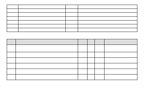
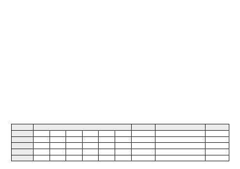
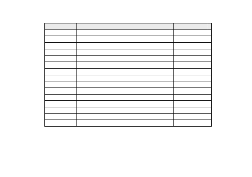
Folder Resources
Visibility Description
Edit
Ai
AI01
AI02
AI03
AI04
Dynamic Analogue inputs
//
di
di01
di02
di03
di04
di05
//
Dynamic Digital Input
//
AO
tC1
AO1
AO2
AO3
//
//
Dynamic Analogue outputs
//
dO
dO01 dO02 dO03 dO04 dO05 dO06 Dynamic Digital outputs
//
CL
HOUr dAtE
YEAr
Clock
YES
21
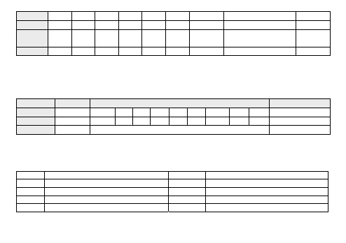
AL
Er00
….
…
…
…
Er99
Dynamic Alarms
//
SP
(1)*
//
//
//
//
//
set point(set)
YES
Hr
CP01
…
CP04 Fn01
…
Fn04
Dynamic Operating hours
Compressors / fans
YES
SC
CP01
…
CP04
Compressor selection
//
As you will be able to see from the table, the setpoint SP and time can be modified and viewed.
(1) * The following type is initially indicated for the set point: SUCTion Set, DISCharge Set. Press the "set" key once
again to view/edit the set point value.
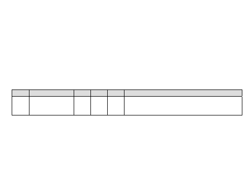
Programming menu
Menu
Folder
Subfolders
Description
Parameters PAr
CF
Ui
St
CP
Fn
AL
Pass
CC
OP Parameters
EU
EU
Eu00
…
…
…
…
…
…
…
Eu99 Alarms log
EUR
EUR
Reset alarm history
CONFIGURING THE MACHINE
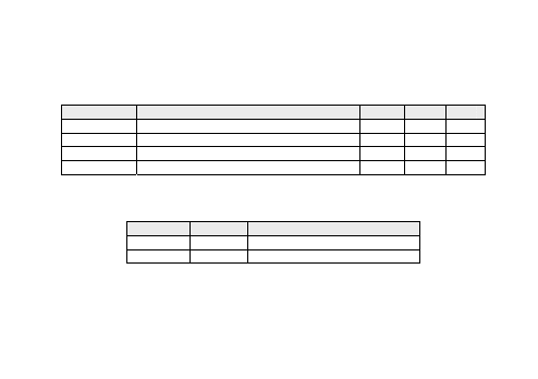
1) ANALOGUE INPUTS (AI3, AI4)
The device has 2 analogue inputs which are configurable using the following parameters:
CF02* Type of analogue AI3 input
CF07
Analogue AI4 input start of scale value
CF03* Type of analogue AI4 input
CF10
Analogue AI3 input differential
CF04 Analogue AI3 input end of scale value
CF11
Analogue AI4 input differential
CF05 Analogue AI3 input start of scale value
CF14** Configuration of analogue AI3 input
CF06 Analogue AI4 input end of scale value
CF15** Configuration of analogue AI4 input
See Parameters F04 … CF11 limits table
22
* If inputs AI3 and AI4 are not set as DI, parameters CF25 and CF26 parameters must be set to 0. Failure to observe
this rule may result in malfunctions.
** If inputs AI3 and AI4 are set as DI, parameters CF14 and CF15 parameters must be set to 0.
*** The unit of measurement (U.M.) is selected based on parameters CF02 and CF03 and parameters UI22 (C°/F°) and
UI23 (Bar/Psi).
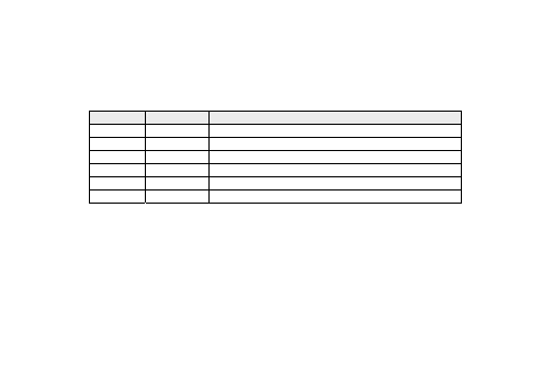
Inputs AI3 and AI4 are configurable as indicated in the following table (CF02 ... CF03):
Value
Type
Description
0
None
Probe not configured
1
DI
Probe configured as potential-free contact digital input
2
NTC
NTC probe range -50.0°C ÷ 99.9 °C
3
4-20mA
Analogue input 4-20 mA
4
0-10V
Analogue input 0-10 V
5
0-5V
Analogue input 0-5 V
Notes:
If an input is configured as NTC, the corresponding parameters are always displayed with the “thermometer” icon.
(UI22=0/1; U.M.= C°/F°)
If an input is configured as 4-20mA, 0-10V or 0-5V, the corresponding parameters are displayed with U.M. =Bar if
UI23=0 with U.M.=Psi if UI23=1.
Parameters CF04 ÷ CF07
Indicate the reading scale analogue limit values for inputs configured as 4-20mA, 0-10V, 0-5V. (Inputs 3 and 4 only)
If the input is not configured as input 4-20mA, 0-10V, 0-5V, the end of scale parameters lose meaning.
23
Parameters CF10 ÷ CF11
Indicate the correction values to add to or subtract from the analogue inputs; by means of this parameter it is
possible to calibrate the temperature/pressure value read by the device. The value given by the instrument reading
“AIxx analogue input differential" will be used by the regulator connected to that probe and will be displayed on-
screen. If the input is configured as a digital input, the corresponding correction parameter must be set to 0
(otherwise the digital input will not function correctly).
Parameters CF14 ÷ CF15
Indicate the logical meaning of the analogue inputs. If the input is configured as a digital input, refer to parameters
CF23..CF26.
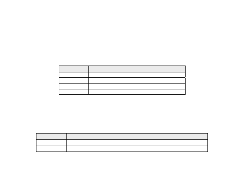
Value
Description
0
Probe disabled
1
Inlet regulation probe *
2
Outlet regulation probe **
3
Not Used
* If CF02=4-20mA, 0-10V, 0-5V then CF14 cannot be set to 2 or 3.
** If CF03=4-20mA, 0-10V, 0-5V then CF15 cannot be set to 1.
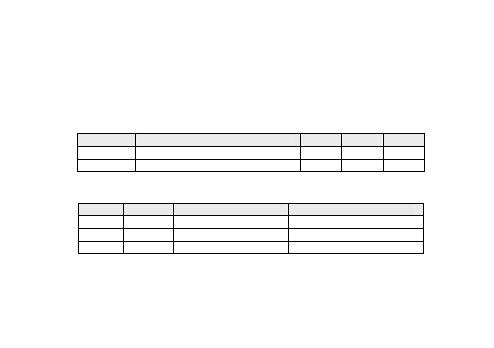
2) DIGITAL INPUTS (DI1, DI2, DI3 DI4 and DI5)
The EWCM32x74 device has 5 digital inputs for potential-free contacts which are configurable by means of user
parameters. If necessary the analogue inputs may also be configured as digital inputs.
Parameter
Description
CF16…CF20
DI1 …DI5 digital input configuration
CF23 …CF26* AI ...AI4 analogue input configuration if configured as digital input
* Set = 0 if AI1 is NOT configured as DI.
24
Parameters CF16 ÷ CF20 and CF23 ÷ CF26
Indicate the logical meaning of the analogue inputs.
Value
Description
± 0
Input disabled
± 1
Outlet pressure switch
± 2
Inlet pressure switch
± 3…± 6
Block compressor 1…4
± 7
Continuous compressor shut-down (inverter)
± 8…± 11 Fan 1..4 thermal switch
± 12
Continuous fan/shared fans thermal switch
± 13
Remote On/Off
± 14
General alarm
± 15 … ± 21 Not used
Polarity is defined below:
Value
Type
Description
+
Positive
Active when contact closed
-
Negative
Active when contact open
If multiple inputs are configured with the same value, only the input with the highest index is active (an OR logic is
not executed)
25
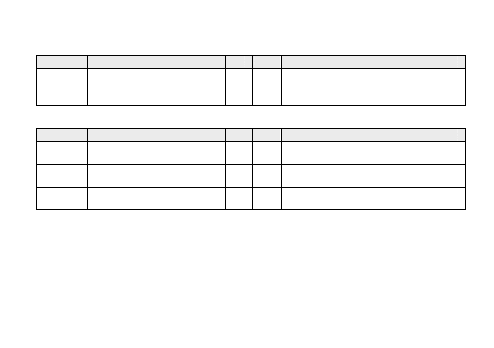
3) HIGH/LOW VOLTAGE DIGITAL OUTPUTS (DO1…DO6)
The device has 5 or 6 digital outputs (depending on model), which are configurable by means of user parameters.
The digital outputs are available as relay contacts (DO01…DO04 and DO06) or open collector low voltage outputs
(DO05). If necessary, the analogue outputs (Triac and PWM, AO1, AO2 and AO3) may also be configured as digital
outputs. See the following paragraph for the characteristics.
Parameter Description
CF45… CF49 DO1… …DO5 digital output configurations
CF50*
Configuration of digital output DO6
* Parameter present in models with 5 relays (Triac not present in these models).
The relay output and open collector can be configured as shown in the table below:
Value
Description
± 0
Output disabled
± 1…± 4
Compressor 1..4 switched on
± 5
Capacity step 1 compressor 1 relay
± 6
Capacity step 1 compressor 2 relay
± 7
Capacity step 1 compressor 3 relay
± 8
Capacity step 2 compressor 1 relay
± 9
Capacity step 2 compressor 2 relay
± 10
Capacity step 3 compressor 1 relay
± 11…± 14 Fan state 1..4
± 15
Alarm status
± 16…± 22 Not used
± 23
Compressor inverter enabling
± 24
Fan inverter enabling
26
Polarity is defined below:
Value
Type
Description
+
Positive
Active when contact closed
-
Negative
Active when contact open
If multiple outputs are configured to run the same resource, the outputs will be activated in parallel.
4) PWM/OPEN COLLECTOR OUTPUTS AO1 AND AO2
The device has two outputs, configurable as PWM or open collector, which pilot the fans/continuous compressors
(via the CFS modules), if configured as PWM, or another resource via external relay if configured as open collector
(On/Off).
The AO1 output is always present whilst the AO2 output is present on models 4150 and 4180 only.
Parameter Description
M.U.
Min
Max
CF34
Enable analogue output AO1
num
0
1
CF35
Enable analogue output AO2
num
0
1
CF37
Analogue AO1 output phase shift
num
0
90
CF38
Analogue AO2 output phase shift
num
0
90
CF40
Analogue AO1 output pulse length (1 unit=69.4 μs)
num
5
40
CF41
Analogue AO2 output pulse length (1 unit=69.4 µs)
num
5
40
CF43
Analogue AO1 output configuration
num
-24*
26*
CF44
Analogue AO2 output configuration
num
-24*
26*
CF51**
Configuration of digital AO1 output
num
-24*
24*
CF52**
Configuration of digital AO2 output
num
-24*
24*
* Values from 16 to 22 are not used.
** Parameters CF51 and CF52 represent the logic assignment of outputs AO01 and AO02 if configured as digital
outputs.
27
Note: Parameters CF37..CF41 have meaning only if the outputs have been configured as Triac outputs; The value to
enter represents the phase shift between voltage and current of the motor connected to the output (obtained from
cos indicated in the motor specifications).
The parameters for output AO2 are available only in models with this output.
Parameter CF34 ÷ CF35
Allow the Triac analogue output to be characterised in the following manner:
Value Description
0
Output configured as digital
1
Output configured as Triac (for pulse piloting)
Parameters CF37 ÷ CF38
Indicate the phase shift values of the pulse output (for adaptation to inductive load) and are active if CF34=1 and
CF35=1.
Parameters CF40 ÷ CF41
Indicate the duration of the pulse output (1 unit=69.4 μs) and are active if CF34=1 and CF35=1.
Parameters CF43 ÷ CF44
Indicate the logical meaning of the Triac analogue outputs and are active if CF34=1 and CF35=1.
28
It is possible to pilot loads with output modulation (value 25-26) or loads with on/off type switching using the Triac as
a switch.
Value
Description
Type
0
Output disabled
On/Off
1 _ 4
Compressor 1..4 switched on
On/Off
5
Capacity step 1 compressor 1 relay
On/Off
6
Capacity step 2 compressor 1 relay
On/Off
7
Capacity step 3 compressor 1 relay
On/Off
8
Capacity step 1 compressor 2 relay
On/Off
9
Capacity step 2 compressor 2 relay
On/Off
10
Capacity step 3 compressor 1 relay
On/Off
11 … 14
Fan status 1..4
On/Off
15
Alarm status
On/Off
16 … 22
Not used
-
23
Compressor inverter enabling
On/Off
24
Fan inverter enabling
On/Off
25
Inverter fan status
Proportional
26
Inverter compressor status
Proportional
Parameters CF51÷ CF52
Indicate the logical meaning of outputs AO01 and AO02 configured as digital outputs and are active if CF34=0 and
CF35=0. For meaning see table entitled configuration of relay and open collector in high/low voltage digital outputs
(DO1 ... DO6).
29
5) TRIAC TC OUTPUT
In certain models, the device has a high voltage Triac output which is typically used for piloting the fans/continuous
compressors.
The output can be configured for proportional operation (constant speed variation) or as ON/OFF; If configured as a
proportional output, the phase parameters and the pulse length of the Triac must be properly configured for better
adaptation to the load characteristics.
Parameter Description
M.U.
Min
Max
CF33
Enable analogue TC output
num
0
1
CF36
Analogue TC output phase shift
num
0
90
CF39
Analogue TC output pulse length (1 unit=69.4 μs)
num
5
40
CF42
Analogue TC output configuration
num
-24
26
Note: Parameters CF36 and CF39 have a meaning only if the outputs have been configured as Triac outputs.
Parameter CF33
Allows the Triac analogue output to be characterised in the following manner:
Value
Type
Description
0
None
Output disabled
1
Triac
Output configured as Triac
Parameter CF36
Indicate phase shift values to pilot Triac with phase cutting in the event of inductive loads; the value to enter
represents the phase shift angle between voltage and current of the motor connected to the output (obtained from
the cos indicated in the motor specifications).
Parameter CF39
Indicate pulse length to pilot Triac (1 unit = 69.4 μs).
30
Parameter CF42
Indicate the logical meaning of Triac analogue outputs. It is possible to pilot loads with output modulation
(value 25-26) or loads with on/off type switching using the Triac as a switch. For meaning see table entitled
Configuration of Parameters CF43 ÷ CF44 in PWM/OPEN COLLECTOR OUTPUTS AO1 and AO2.
6) LOW VOLTAGE ANALOGUE AO3 OUTPUT
In certain models, the device has 1 low voltage analogue output configurable by means of the user parameters.
Depending on the application, the output may be available as 0-10V or 4-20mA
AO3 configuration
Parameter Description
M.U.
Min
Max
CF27
Type of output analogue AO3
num
0
2
CF30
Configuration of analogue output AO3
num
-24
26
Parameter CF27
Allows the Triac analogue output AO3 to be characterised in the following manner:
Value
Type
Description
Notes
0
0-10V
Analogue output - voltage Modulated piloting or on/off
1
4-20mA Analogue output - current Modulated piloting or on/off
2
0-20mA Analogue output - current Modulated piloting or on/off
Parameter CF30
Indicates the logical meaning of the analogue output. It is possible to pilot loads with output modulation
(value 25-26) or loads with on/off type switching using the output as switch 0-10V. For meaning see table
entitled Configuration of Parameters CF43 ÷ CF44 in PWM/OPEN COLLECTOR OUTPUTS AO1 AND AO2.
31
COMPRESSOR CONTROL
The device can be configured to manage an inverter compressor or one or more homogenous digital compressors
(max. 4) by setting parameter CP22:
Parameter Description
Min Max Notes
CP22
Number of compressor steps
per circuit
0
4
0=inverter compressor.
≠0=CP22 represents the number of digital
compressors.
With digital compressors it is also possible to define the number of power stages by setting parameters CP23, CP24
and CP25:
Parameter Description
Min Max Notes
CP23
Number of compressor steps 1
1
4
1=whole compressor
≠1= CP23 - 1 is the number of Power stages.
CP24
Number of compressor steps 2
1
3
1= whole compressor
≠1= CP24 - 1 is the capacity step
CP25
Number of compressor steps 3
1
2
1= whole compressor
2= the number of Power stages is 1
Regulation is proportional or Neutral Zone (ZN) as a function of the inlet probe (temperature or pressure control).
In the case of pressure regulation, probe AI3 must be used (high resolution probe).
In local or remote OFF the compressors are switched off.
The compressors and/or relative Power stages can be directly connected to the controller via the Triac output or relay
or indirectly connected via an external module (connected to controller via an PWM or analogue output):
Direct Triac TC output.
Indirect “PWM” output AO1, AO2 (needs external module for piloting the inverter compressor).
Indirect 4..20mA / 0..20mA / 0..10Vcc output AO3 (needs external module for piloting inverter compressor).
Relay output for piloting digital compressors (whole or segmented).
Digital Output DO5 (Open Collector) using an external relay.
One or more digital inputs can be configured as compressor block inputs:
Digital inputs DI1…DI7.
Analogue inputs AI3 …AI4 if configured as digital inputs.
It is also possible to configure a relay as compressor INVERTER enabling output.
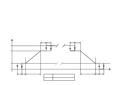
Inverter compressor control
The operating mode depends on parameter ST02. Cold mode St02=1. Hot mode St02=0.
The inverter compressor control is proportional as a function of the inlet probe value. The following diagram
indicates the compressor speed as a function of the regulation probe in the case of regulation with lateral set point
(St01=1). In the case of central set point (St01=0), the proportional band is centred in the set point:
CP06 CP04
CP03
CP00
CP20
CP19
CP18
OFF
CP07
CP05
A
B
CP06
CP04
CP03
CP00
CP07
CP05
A
B
Cooling (St02 = 1)
Heating (St02 = 0)
Speed
%
(°C/°F/Bar/Psi)
Keys
A
Minimum cut-off
B
Saturation cut-off
32
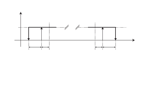
CP06
CP04
Compressor
Inverter
Enabling
Cooling
Heating
ON
OFF
Regolator
probe
Setpoint
(CP00)
CP06
CP04
Setpoint
(CP00)
The digital inverter enabling output is activated in each case in which the analogue output has a value other than 0%.
The above drawing represents only the nominal case in which the cut-off hysteresis is enabled at the minimum.
Parameters CP08 (enable minimum cut-off) and CP09 (enable saturation cut-off) activate or deactivate the cut-off
function. Note that, if the minimum cut-off is disabled, the speed of the inverter compressor goes from 0 to the
minimum speed when the regulation probe reaches the set point from "below". If the regulation probe reaches the
set point from “above”, the speed will go from minimum speed to 0. Similarly if the saturation cut-off is disabled, the
speed of the inverter compressor goes from continuous regulation to maximum speed when the regulation probe
reaches Set point+Proportional Band from "below”. If the regulation probe reaches Setpoint+Proportional Band from
"above" there will be continuous regulation between maximum and minimum speed.
Regulation probe error: the inverter compressor will be piloted at the speed set by parameter CP21.
33

34
Digital compressor control
The regulator calculates the number of refrigeration resources required by the system through a policy of assigning
resources selectable with parameter CP10 (Activation policy).
Activating or deactivating power steps must respect the activation and release times for resources CP15 and CP16
which are loaded on activation/release.
In alarm conditions, (e.g. due to the intervention of a compressor block) any reduction in power required is
calculated immediately. however, the power make-up must always keep to the time intervals described above,
particularly the activation time of the CP15 resources.
Proportional band: this occours if bit0 of parameter ST04 equals 0 (this occours for St04=0 and St04=2).
The operation depends on the parameter ST02: Cooling mode if St02=1 and Heating mode if St02=0.
The digital compressor control is stepped as a function of the inlet probe value.
The regulator activates a certain number of resources (power steps) to reach the Set point configured. The number of
resources required is linked to the difference between the value measured by the inlet probe and the set point;
Naturally, the greater this difference, the greater the number of resources required to reach the setpoint. The
temperature /pressure interval between activation of one power step and the next depends on the proportional band
and the number of resources present.
In the event of a regulation probe error, the number of active power steps is calculated as a percentage set at
parameter CP21 of the complete number of steps.
The following is an example of regulation with lateral set point (St01=1). In the case of central set point (St01=0) the
proportional band is deemed to be centred in the set point.
CP03
CP03
CP00
Step
3
2
1
0
CP03
CP00
nr. of steps
CP03
nr. of steps
(°C/°F/Bar/Psi)
Cooling (St02 = 1)
Heating (St02 = 0)
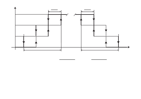
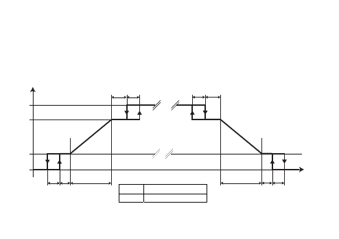
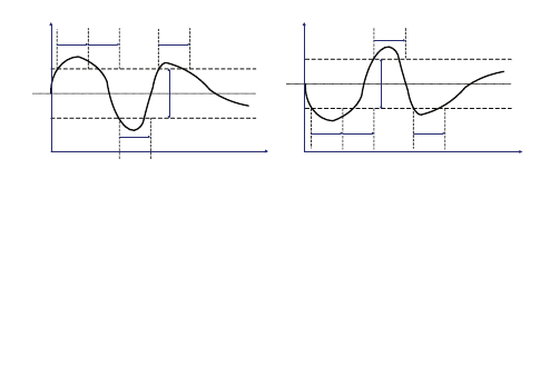
Neutral zone: this occurs if bit0 of parameter ST04 equals 1 (this occurs for St04=1 and St04=3).
The operation depends on the parameter ST02: Cooling mode if St02=1 and Heating mode if St02=0.
The main function of the regulator consists in activating/deactivating a number of resources (discrete power steps)
linked to the time in which the intake probe takes on values outside of the symmetric proportional band in
comparison to the set point value.
For the cooling mode, for example, when the value read by the intake probe exceeds the SET POINT+(BANDA)/2
threshold value, if the increasing interstep time (set with CP15) has already expired, an increase in power is
implemented and the CP15 time is recounted (increasing interstep time). If the value read by the intake probe
remains in this range, an additional power increase is activated for each “increasing interstep time” (set with CP15).
The operation is similar for switching off, with the times set by parameter CP16 (decreasing interstep time).
35
No variation in power is required within the PROPORTIONAL BAND. Hysteresis is not included in this algorithm.
All interstep times are resynchronised upon the activation/deactivation of a new compressor combination.
In the case of an regulation probe error, the number of active steps is calculated as a percentage set for the CP21
parameter of the total number of steps.
Set point
+1
+1
+1
-1
T inc.
T inc.
T inc.
T dec.
Time
Regulator probe
Band
Set point
+1
+1
+1
-1
T inc.
T inc.
T inc.
T dec.
Time
Regulator probe
Band
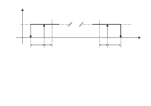
Compressor timing
The switching on and off of a compressor (inverter or digital) must meet the following requirements:
Minimum time between switching off/on (parameter CP12). This is the minimum delay between switching off
and switching on;
Minimum time between switching off/on (parameter CP14). This is the minimum delay between switching on
and switching off;
Minimum time between switching off/on (parameter CP13). This is the minimum delay between switching on
and switching on again;
36
37
The activation and deactivation of power steps for digital compressors must respect the activation and release times
for resources (parameters CP15 and CP16).
Power stages
For a segmented compressor in which the number of steps corresponds to the number of segments plus one, the
segmentation actuation mode depends on parameter CP11.
Parameter Description
Min
Max
M.U.
CP11
Enable/disable sequence of relays associated to compressor
power stages in the suction section
0
2
Num
For a whole compressor there are no power stages, so the compressor supplies either 0% or 100% of its power.
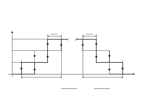
Example of compressor with 3 power stages (4 regulation power steps)
The compressors can supply 0%, 25%, 50%, 75% or 100% of their power.
CP11=0
CP11=1
CP11=2
Power ACC
STG 1 STG 2 STG 3 STG 1 STG 2 STG 3 STG 1
STG 2
STG 3
100%
ON
ON
ON
ON
75%
ON
ON
ON
ON
ON
50%
ON
ON
ON
ON
ON
25%
ON
ON
ON
ON
ON
0%
Compressor switch-on policies
The selection policy that the inlet regulator applies in the distribution of the refrigerator resources is defined by
parameter CP10. The policies available are saturation, balancing and fixed sequence.
38
Parameter Description
Min Max M./U. Notes
CP10
Activation Policy
0
2
Num 0= fixed sequence 1= balancing 2= saturation
The selection policies are based mainly on the hours of operation of the compressors.
They come into play when the regulator requests the activation/deactivation of a step. This request is then distributed
to the most suitable compressor according to the compressor selection policy selected using CP10.
Compressor saturation: The saturation policy distributes all resources equally over the smallest number of
compressors possible, so far as this is compatible with other requirements, such as: compressor safety timings. The
resulting allocation is intended to have the largest possible number of compressors switched off at any one time.
Compressor balancing: The balancing policy distributes all resources equally over the largest number of compressors
possible, so far as this is compatible with other requirements, such as compressor safety timings: The resulting
allocation is intended to have the greatest possible equalization of power output levels in the compressors at any one
time.
Fixed sequence compressors: The fixed sequence policy distributes all resources starting from the compressors with
the lowest index, so far as this is compatible with other requirements, such as compressor safety timings The resulting
allocation is such as to obtain, at any given time, a maximum delivery of the compressors with lower indexes.
Hours of use of compressors
The operating time of the compressors is stored every hour in EEPROM for the purpose of:
Managing the compressor switch-on policies;
Enabling the signalling of an alarm if the compressor operating hours exceed the maximum operating hours
threshold.
39
Parameter
Description
Min
Max
M.U.
CP17
Maximum hours of use for compressor
0
6500
Hours*10
The hours of use of each single compressor can be reset from the State menu.
Selecting/deselecting compressors
Each individual compressor can be selected from the State menu. Deselection of a compressor entails the following:
The compressor availability is set to zero
Zero setting of all its possible alarms
Its alarms are not managed
Compressor block
Management of this alarm applies both to step compressors and to compressors with continuous regulation and is
active if the compressor is selected. The activation of this alarm blocks the compressors in use. In the case of step
compressors, the availability of another compressor is checked at the same time as the compressor block. If it is
available it will be selected depending on the policy (CP10) and immediately switched on.
CONDENSATION CONTROL
The device can be configured to manage an inverter fan or one or more homogenous digital fans (max. 4) by setting
parameter Fn25:
Parameter Description
Min Max M.U Notes
Fn25
Number of fans per step for fan coil
-1
4
Num
-1 = no condensation.
0 = continuous fan.
>0 = Fn25 represents the number of
digital fans.

40
By setting parameter Fn25=-1 it is also possible to define that the fan is absent (no condensation) and the relative
regulator will not be actuated. If a probe is configured as a temperature probe or outlet pressure probe, the
condensation regulation is proportional or Neutral Zone (NZ). In the case of pressure regulation, the AI4 probe must
be used (low resolution probe). If no outlet probe has been configured, the fans will be piloted by default depending
on the operating mode (Heat or Cool). In local or remote OFF the fans are switched off.
The fan can be directly connected to the controller via the Triac output or relay or indirectly connected via an
external module (connected to controller via a PWM or analogue output):
•
Direct Triac TC output
•
Indirect “PWM” output AO1, AO2 (needs external module for piloting fan).
•
Indirect 4..20mA / 0..20mA / 0..10Vcc output AO3 (needs external module for piloting fan).
•
Relay outputs for piloting digital fans
•
Digital Output DO5 (Open Collector) using an external relay.
One or more digital inputs can be configured as fan thermal switch:
•
Digital inputs DI1…DI7.
•
Analogue inputs AI3 …AI4 if configured as digital inputs.
It is possible to configure a relay as fan INVERTER enabling output.
INVERTER COMPRESSOR CONTROL
Pick-up
Each time the fan starts, the exchanger fan is supplied at the maximum voltage level, hence the fan runs at the
speed established by parameter Fn23 (max. pick-up speed) for a time equal to the value set via parameter Fn13
(pick-up time). After this time, the fan will continue at the speed set by the regulator. However if the regulator
wants to turn the ventilation off during the pick-up time, the fan will be switched off. The pick-up time will be
reloaded at the next start.
The speed specified by parameter Fn23 may be reached in one of two ways depending on the value of parameter
Fn12 (mode for reaching maximum pick-up speed):

41
•
0 = the regulator immediately sets the output proportional to the speed specified by parameter Fn23 and
maintains this speed for the time specified by parameter Fn13.
•
1 = the regulator actuates the proportional output according to a ramp that allows the speed specified by
parameter Fn23 to be reached in the time specified by parameter Fn13.
If Fn13= 0, pick-up is disabled. The regulation may be at central set or side set depending on parameter St01.
The use of the interstep times Fn16 and Fn17 is enabled and they are loaded during the instrument switching on and
switching off phases. To prevent uncertainty, it is recommended to set the values to 0.
Regulation
The operating mode depends on parameter ST02. Cold mode St02 = 1. Hot mode St02 = 0.
If no condensation probe has been allocated (temperature or pressure), the fan ON/OFF switch will be controlled on
request from the compressor in cooling mode or in heating mode if Fn10 = 1, otherwise if Fn10 = 0 the fan is always
ON.
When the fan is ON it is piloted at the speed set by parameter Fn24. If however a condensation probe has been
allocated, the fan control is proportional as a function of the condensation probe value. The fan may be regulated
independently from the compressor or at the request of the compressor depending on parameter Fn10 (operation on
request by compressor): If Fn10=0 then condensation is controlled independently from the compressor, however if
Fn10=1 then the fan is OFF when all of the compressors available are OFF.
The minimum cut-off is bypassed for the time specified by parameter Fn14 on start-up of the compressor. If the
regulator requests the cut-off during this period the fan is piloted at the minimum speed set by parameter Fn20.
Note: The cut-off does NOT force the fans to be switched on but only prevents them from being switched off. The
following diagrams illustrates the fan speed and the digital inverter enabling output as a function of the regulation
probe in the case of regulation with lateral set point (St01=1). In the case of central set point (St01=0), the
proportional band is deemed to be centred in the set point:
Parameters Fn08 (enable minimum cut-off) and Fn09 (enable saturation cut-off) activate or deactivate the cut-off
function. Note that if the minimum cut-off is disabled, the speed of the fan goes from 0 to the minimum speed when
the regulation probe reaches the set point from “below”. If the regulation probe reaches the setpoint from “above”,
the speed will go from minimum speed to 0.
Similarly, if the saturation cut-off is disabled, the fan speed goes from continuous regulation to maximum silent speed
when the regulation probe reaches the Set Point+Proportional Band from "below”.
If the regulation probe reaches Set point+Proportional Band from "above", there will be continuous regulation
between maximum silent speed and minimum speed.
Fn06
Fn04
Fn03
Fn00
Speed
%
Cooling (St02 = 1)
Heating (St02 = 0)
Fn22
Fn21
Fn20
OFF
Fn07
Fn05
A
B
(°C/°F/Bar/Psi)
06
Fn04
Fn03
Fn00
Fn07
Fn05
A
B
Key
A Minimum cut-off
B
Saturation cut-off
42
Fn06
Fn04
Cooling
Heating
ON
OFF
Setpoint
(Fn00)
Fn06
Fn04
Setpoint
(Fn00)
Regolator
probe
Fan
Inverter
Enabling
The digital inverter enabling output is activated in each case in which the analogue output has a value other than 0%.
The above drawing represents only the nominal case in which the cut-off hysteresis is enabled at the minimum.
Inverter preventilation (cold mode only)
If parameter Fn10=1 (if the compressor is OFF, the fan is OFF) and Fn15<>0, the preventilation is also active. Before
the compressor is switched on, the fan is switched on for a time equal to Fn15; the fan speed is proportional to the
value of the regulation probe. However, if during this period the regulator requests the switching off of the fan, the
fan will be piloted at the minimum speed set by parameter Fn20. This is to avoid the compressor switching on when
the condensation probe values are excessively high. If, at the end the preventilation, the regulator does not request
fans, the fan is switched off immediately. The preventilation is reset if the right parameter conditions are present and
if the inlet request is zeroed and then returns (even if the request is cancelled by its alarm or the outlet alarm).
In the event of a regulation probe error, the fan ON/OFF switch will be controlled on request from the compressor.
When the fan is ON it is piloted at the speed set by parameter Fn24.
43

44
DIGITAL FAN CONTROL
Pick-up
On each activation request by the regulator, all of the exchanger fans are activated simultaneously for a time equal to
the value set using parameter Fn13 (pick-up time).
After this time has elapsed, the fans will be piloted at the speed set by the regulator. If, during the pick-up time, the
regulator wants to turn the ventilation off, the fans will be switched off. The pick-up time will be reloaded at the next
start. If Fn13= 0 the pick-up is disabled.
Activation and deactivation of power steps must respect the activation and release times for resources Fn16 and
Fn17, which are loaded at activation/release.
The use of the interstep times Fn16 and Fn17 is enabled in the case of a continuous fan and they are loaded during
the instrument switching on and switching off phases. To prevent uncertainty, it is recommended to set the values to 0.
Proportional band regulation: this occurs if bit1 of parameter ST04 equals 0 (this occurs for St04=0 and St04=1).
The operation depends on the parameter ST02: Cooling mode if St02=1 and Heating mode if St02=0.
If no condensation probe has been allocated (temperature or pressure), the fan ON/OFF switch will be controlled on
request from the compressor in cooling mode or in heating mode if Fn10=1, otherwise if Fn10=0 the fan is always
ON. During the ON phase, the number of fans switched on in respect to the number of those present depends on the
value set at parameter Fn24. If however a condensation probe has been configured, the fan control is by steps as a
function of the condensation probe value.
The regulator activates a certain number of resources (power steps) to reach the Set point configured (Fn00). The
number of resources required is linked to the difference between the value measured by the condensation probe and
the set point; The greater this difference, the greater the number of resources required to reach the set point. The
temperature/pressure interval between application of one power step and the next depends on the proportional
band and the number of resources present.
The fan may be regulated independently from the compressor or at the request of the compressor, depending on
parameter Fn10 (compressor operation on request).
If Fn10=0 then the condensation control is independent of the compressor, if, however, Fn10=1 then the fan is off
when all of the compressors available are off.
The cut-off at minimum is bypassed for the time set at parameter Fn14 after the compressor is activated. If the
regulator requests the switching off of the fans during this time, the fans will be piloted at the minimum speed (1
step). The following is an example of regulation with lateral set point (St01=1). In the case of central set point
(St01=0), the proportional band is deemed to be centred in the set point:
Fn03
Fn03
Fn00
Step
3
2
1
0
Fn03
Fn00
nr. of steps
Fn03
nr. of steps
(°C/°F/Bar/Psi)
Cooling (St02 = 1)
Heating (St02 = 0)
Neutral zone regulation: this occurs if bit1 of parameter ST04 equals 1 (this occurs for St04=2 and St04=3).
The operation depends on the parameter ST02: Cooling mode if St02=1 and Heating mode if St02=0.
If a condensation probe has not been allocated (in temperature or in pressure) the fans are On OFF controlled on
request by the compressor in cooling mode or in heating mode if Fn10=1 otherwise, if Fn10=0, the fan is always ON.
45

46
During the ON phase, the number of fans that are switched on in comparison to the number of those present is a
function of the value set for parameter Fn24.
If a condensation probe has been allocated, the fan control will be in steps with a neutral zone in function of the
value of the condensation probe and the set times.
Fan regulation can be done independently of the compressor or upon request of the compressor in function of the
parameter Fn10 (operation on compressor request): if Fn10=0 condensation control is independent of the
compressor, if Fn10=1 instead, if all of the available compressors are off, the fan is off.
The minimum cut-off is bypassed for time set for parameter Fn14 from switching on the compressor. During this
period, if the regulator requests the fans to switch off, they will be controlled at the minimum speed (one step).
The main function of the regulator with a neutral zone consists in activating/deactivating a number of resources
(discrete power steps) linked to the time in which the delivery probe takes on values outside of the symmetric
proportional band in comparison to the set point value.
For the cooling mode, for example, when the value read by the delivery probe exceeds the SET POINT+(BANDA)/2
threshold value, if the increasing interstep time (set with FN16) has already expired, an increase in power is
implemented and the FN16 time is recounted (increasing interstep time). If the value read by the delivery probe
remains in this range, an additional power increase is activated for each “increasing interstep time” (set with FN16).
The operation is similar for switching off, with the times set by parameter FN17 (decreasing interstep time). Within
the PROPORTIONAL BAND, no variation in power is required.
Hysteresis is not included in this algorithm.
The addition and removal of power steps must respect the activation and release times between resources Fn16 and
Fn17 that are loaded upon their activation/release. In case of Neutral Zone regulation, the position of the Setpoint is
always central, independently from the value of the parameter St01. An example is shown below:
Set point
+1
+1
+1
-1
T inc.
T inc.
T inc.
T dec.
Time
Regulator probe
Band
Set point
+1
+1
+1
-1
T inc.
T inc.
T inc.
T dec.
Time
Regulator probe
Band
Digital fan preventilation (cold mode only)
If the parameter Fn10=1 (if the compressor is OFF, the fan is OFF) and Fn15<>0, the preventilation function is active.
Prior to switching on the compressor, the fans will be activated for a time equal to Fn15; the number of fans activated
is proportional to the value of the regulation probe but is not less than 1. This is to avoid the compressor switching
on when the condensation probe values are excessively high.
If, at the end the preventilation, the regulator does not request fans, the fans are switched off immediately. The
preventilation is reset if the right parameter conditions are present and if the inlet request is zeroed and then returns
(even if the inlet request is cancelled by its alarm or the outlet alarm). In the event of a regulation probe error, the
fan ON/OFF switches will be controlled on request from the compressor. During the ON phase, the number of fans
switched on in respect to the number of those present depends on the value set at parameter Fn24.
47

48
Digital fans rotation
In the case of step fans, rotation of the fans can be controlled during activation and release by means of parameter
Fn11. If Fn11=0 (fixed sequence), the activation sequence is fan 1, fan 2, ....fan n; The sequence is inverted during
deactivation, e.g. fan n..., fan 2, fan 1.
If Fn11=1 (operating hours), during activation the fan which worked the least is selected, while during deactivation
the fan which has worked the most is selected. The aim is to balance out the operating hours between all fans.
Maximum fans stop time
Parameter Fn18 indicates the maximum time for which the fans (continuous or digital) may remain off. Once this
time has elapsed, fan pick-up is forced for the time specified by Fn26.
If, during the pick up time, the compressors are switched on, the minimum cut-off bypass will not be respected at the
end of the pick-up time, and in the absence of a request by the fan regulator the fans will immediately be switched
off.
If, during the pick up time, preventilation is activated due to the compressors being switched on, it will remain active
for any remaining time after the end of the pick up time.
The function is disabled if Fn18=0 or if Fn26=0.
The time the fans are off is reinitialised each time the device is switched on.
Fan operating hours
The operating time of the fans is stored every hour in EEPROM for the purpose of:
Managing the fan rotation function based on the operating duration.
Enabling the signalling of an alarm if the fan operating hours exceed the maximum operating hours threshold.
Parameter Fn19 enables the maximum number of fan operating hours to be set.
The hours of use of each individual fan can be zeroed from the State menu.

49
Fans thermal switch
The intervention of the digital fan thermal protection is blocked for the correctly used fan.
If another fan is available it will be selected depending on the policy (Fn11) and immediately activated. The
contemporaneous intervention of the thermal protections of all of the digital fans causes an alarm which blocks the
machine.
In the case of fans with continuous control or digital fans in which a single common thermal fan has been configured,
the tripping of the thermal switch causes the machine to shut down.
ADVANCED FUNCTIONS
On/off device
The activation/deactivation of the device used for controlling resources may be carried out via keyboard or digital
input:
ON/OFF from keyboard: The device may be switched on or off using the keyboard from the Folder
Programming menu OP. This function is not active if the ON/OFF is configured via digital input (e.g. for DI5,
CF20=13). In OFF mode, the screen will display the word OFF.
ON/OFF via Digital Input: If a digital or analogue input is configured for this function, the device state
depends on the input state. In OFF mode, the word OFF will flash on-screen. ON/OFF via keyboard is not
active.

50
Recording operating hours
The device records the operating hours of the compressors and fans; This data is visible in the Hr folder and is called
CP0n (nth compressor hours), Fn0n (nth fan hours).
For values lower than 9999 the entire value is displayed, for higher values the hours/100 are displayed and the
decimal point is activated. The maximum limit of recorded hours is 65535; once this value has been reached the
device will automatically reset the hour counter. The display is dynamic, e.g. only the hours of actually available
resources will be displayed. It is possible to set a maximum operating hours threshold, which generates an alarm as
soon as it is reached (for example, for compressor or fan maintenance)
The alarm does not cause the exclusion of the regulator resource, and is displayed on-screen with a code depending
on the resource that has exceeded the permitted operating hours. The alarm does not reset the operating hours.
The operating hours can be reset manually from the states menu, Hr folder; When displaying the hours of a
particular resource, press and hold the “set” key to zero the operating hours of the resource (and not those of
other resources).
Real Time Clock (RTC)
The device can be supplied with a clock which makes it possible to store the time at which alarm events occurred.
The parameter CF72 is used to activate/deactivate the clock.
The current time is set using the appropriate menu as shown in the navigation menu diagram; use the Set key to
confirm the value once the time and date have been modified. The value will only be saved on exiting the menu
(timeout or by pressing the Esc key).
Once the time is set, the instrument must be connected for several hours to fully charge the back-up battery.
The switch between legal/solar time is not automatic.
The device does not perform a real time control on the correctness of the date set; this means that it is
possible to set a non-existent date such as 30/02/2007 without the machine noticing.

51
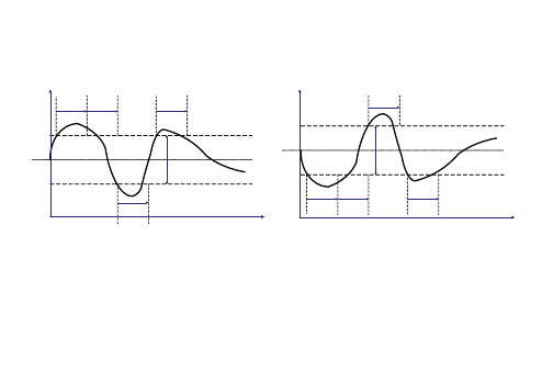
ALARMS
The alarms can be one of 3 types:
Automatic reset alarm: alarm active if the cause of the alarm is present, otherwise not.
Manual reset alarm: alarm active if the cause of the alarm is present, if the cause of the alarm has ceased the alarm
can only be reset manually (by simultaneously pressing the UP and DOWN keys).
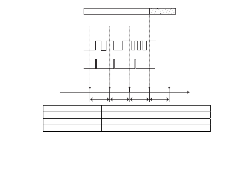
Semi-automatic alarm: Behaves like an automatic alarm as long as the number of events in the unit of time is less
than a certain value, otherwise like a manual alarm. The unit of time can be programmed using parameter AL00, the
number of responses can be individually programmed for each semi-automatic alarm.
Alarm events are stored with a time resolution of T=(AL00/32) minutes; multiple events occurring in period T are
counted as one single event.
Manual reset performed while an alarm cause is present does not enable the alarm to be reset.
It is possible to force the semi-automatic alarm to be considered only as an automatic alarm or a manual reset alarm,
by setting the appropriate number of alarm responses:
If the number of responses=0, the alarm is managed as a manual reset alarm only. At the first response, the
alarm will become active and can be reset manually;
If the number of responses=33 the alarm is managed as an automatic alarm only. At the first response, the
alarm becomes active but automatically resets when the cause has ceased;
A bypass time is defined for semi-automatic alarms and can be set by parameter. It allows the alarm signal to be
delayed, for example to enable the system to stabilise.
If the bypass time = 0, the alarm response is immediate (see the following diagram).
Alarm signal
See special display diagram
AL00/32
AL00/32
AL00/32
AL00/32
3=AL10
2
1
0
Counter
Time
Sampling
Events
Alarm
Manual
OFF
ON
1 event
1 event
1 event
0
1
AUTOMATIC
AUTOMATIC
automatic reset
Manual manual
reset
AL00/32 sampling
time
Events
no. of considered events. Event 3 = (AL10)
Silence and reset alarms
Alarm silencing consists of the forced deactivation of the output configured as an alarm and is performed by pressing
any key (in the presence of an alarm). Silencing has no effect on the alarm state, it only affects the signal itself; The
alarm LED, which is a fixed light in the presence of an alarm, becomes a flashing light when silenced. Alarm reset
consists of zeroing all pending manual reset alarms.
52
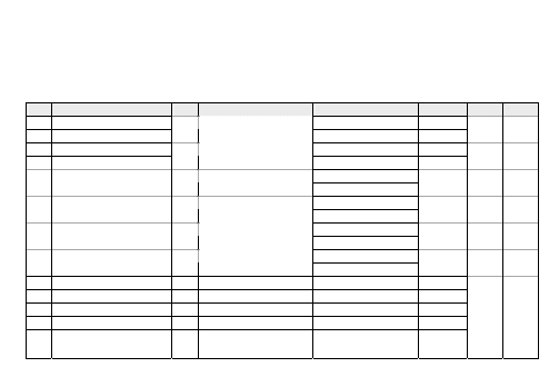
53
This is done by simultaneously pressing the UP + DOWN keys. To reset a manual reset alarm which is still active, the
alarm must be first deactivated and then immediately re-entered. This causes a new entry to be stored in the alarms
log and resets the alarm relay (silenced by key).
Alarms list with description and activation parameters
A= By-pass
C= n° of responses
Code Description
Type Cause
(Set) Activation
Hysteresis A 1) C 2) 3)
Er01 Low pressure switch - inlet
inlet probe<= CP00
Er02 High pressure switch - inlet
EVE Inlet
gas pressure switch
inlet probe> CP00
AL02 AL01
Er03
Low pressure switch - outlet
outlet probe<= Fn00
Er04
High pressure switch - outlet
EVE Outlet
pressure switch
outlet probe> Fn00
AL04 AL03
AL17 if St03=0
Er05 Inlet probe maximum
EVE inlet probe>set activation
CP00+AL17 if St03=1
AL18
AL08 AL07
AL19 if St03=0
Er06 Inlet probe minimum
EVE Inlet probe<set activation
CP00-AL19 if St03=1
AL20
AL06 AL05
AL21 if St03=0
Er07 Outlet probe maximum
EVE Outlet probe>set
activation
Fn00+AL21 if St03=1
AL22
AL12 AL11
AL23 if St03=0
Er08 Outlet probe minimum
EVE Outlet probe<set
activation
Fn00-AL23 if St03=1
AL24
AL10 AL09
Er09 Block compressor 1
EVE Block compressor 1
Er10 Block compressor 2
EVE Block compressor 2
Er11 Block compressor 3
EVE Block compressor 3
Er12 Block compressor 4
EVE Block compressor 4
Er13 Continuous compressor
shut-down
EVE Continuous compressor
shut-down
AL14 AL13

54
Code Description
Type Cause
(Set) Activation
Hysteresis A 1) C 2) 3)
Er14 Fan thermal switch 1
EVE Fan thermal switch 1
Er15 Fan thermal switch 2
EVE Fan thermal switch 2
Er16 Fan thermal switch 3
EVE Fan thermal switch 3
Er17 Fan thermal switch 4
EVE Fan thermal switch 4
Er18
Continuous fan thermal
switch
shared fans thermal switch
EVE
Continuous fan thermal
switch
shared fans thermal
switch
AL16 AL15
Er19 Operating hours exceeded
Compr. 1
MAN Operating hours
comp1>CP17
Er20 Operating hours exceeded
Compr. 2
MAN Operating hours
Com2>CP17
Er21 Operating hours exceeded
Compr. 3
MAN Operating hours
Comp3>CP17
Er22 Operating hours exceeded
Compr. 4
MAN Operating hours
comp4>CP17
Er23 Operating hours exceeded
Compr. Inverter
MAN Operating hours inv
comp>CP17
Er24 Operating hours exceeded
Fan 1
MAN Operating hours
fan1>Fn19
Er25 Operating hours exceeded
Fan 2
MAN Operating hours
fan2>Fn19
Er26 Operating hours exceeded
Fan 3
MAN Operating hours
fan3>Fn19
Er27 Operating hours exceeded
Fan 4
MAN Operating hours
fan4>Fn19
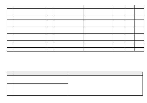
55
Code Description
Type Cause
(Set) Activation
Hysteresis A 1) C 2) 3)
Er28 Operating hours exceeded
Inverter fan
MAN Operating hours inv
fan>Fn19
Er29 General alarm
MAN General alarm
Er30 Inlet probe error
AUT Operation connection
defect
Er31 Outlet probe error
AUT Operation connection
defect
Er33 RTC communication error
alarm AUT Clock broken
Er34 Alarm RTC register value AUT Clock not regulated
Er35 Configuration error alarm AUT Configuration incorrect
Er37 Alarms log full signal
MAN N° of log events > AL25
Note: 1) If “bypass time” = “not present”, the alarm is immediately active.
2) If “N° responses in sample window” = 0, the alarm is always in manual reset
3) If “N° responses in sample window” = >32 the alarm is always in automatic reset mode
Alarm list with actions and notes
Code Action
Notes
Er01 Blocks all compressors and fans
Er02
Blocks all compressors and fans:
- at maximum power (Fn22) in Cool
- OFF in Heat
AL02 is loaded for digital compressors whenever a power
variation is applied to the system which is not due to the alarm
itself; for the inverter compressor when activated. If suction
probe in error, minimum alarm is always signalled.
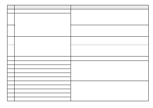
56
Code Action
Notes
Er03 Blocks all compressors and fans
Er04
Blocks all compressors and fans:
- at maximum power (Fn22) in Cool
- OFF in Heat
AL04 is loaded for digital fans whenever a fan is
activated/deactivated, except when the deactivation is due to
the alarm itself; for the inverter fan when activated. If delivery
probe error occurs, minimum alarm is always signalled.
Er05
Blocks all compressors and fans:
- at maximum power (Fn22) in Cool
- OFF in Heat
If inlet probe error occurs, management alarm disabled
Er06 Blocks all compressors and fans
If inlet probe error occurs, management alarm disabled
Er07
Blocks all compressors and fans:
- at maximum power (Fn22) in Cool
- OFF in Heat
If outlet probe error occurs, management alarm disabled
Er08 Blocks all compressors and fans
If outlet probe error occurs, management alarm disabled
Er09 Exclude compressor 1
Er10 Exclude compressor 2
Er11 Exclude compressor 3
Er12 Exclude compressor 4
Er13 Exclude continuous compressor
AL14 is loaded on activation of the block digital input
Er14 Exclude fan 1
Er15 Exclude fan 2
Er16 Exclude fan 3
Er17 Exclude fan 4
Er18 Blocks the system
AL16 is loaded on activation of the block digital input

57
Code Action
Notes
Er19
Er20
Er21
Er22
Er23
Message
Alarm condition reset by zeroing the number, operating time
and resetting the alarm. If Cp17=0 management alarm disabled.
Er24
Er25
Er26
Er27
Er28
Message
Alarm condition reset by zeroing the number, the running time
and resetting the alarm. If Fn19=0, management alarm disabled.
Er29 Blocks the system
Er30
Operation of compressor regulator from
CP21.
Management of inlet analogue maximum and minimum alarms
disabled. Inlet pressure switch response alarm signalled as low
pressure alarm.
Er31 Operation of outlet regulator from FN24.
Management of outlet analogue maximum and minimum
analogues alarms disabled. Outlet pressure switch response
alarm signalled as low pressure alarm.
Er33
Er34
Message
Reset alarm by resetting the clock with current
day/hour/minute and switching off/restarting.
Er35 Blocks the system
Signalled at power-on of the device or a parameter has been
modified
Er37 Message
If AL25=0, alarm disabled. Reset with log deletion
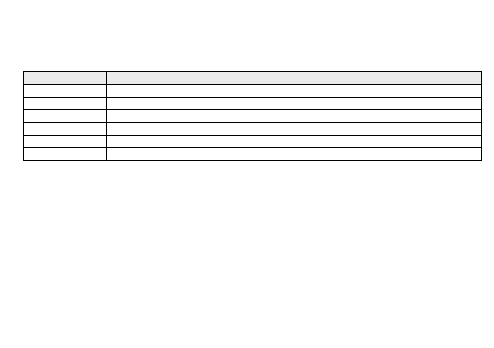
58
Alarms log
The alarms log enables activated alarms to be recorded with the information given below.
(If the device does not have a clock, the log can still be used but information relating to the hour and date will not be
available).
Code
Description
Erxx
Alarm code
xx:zz
Event start hour/minute
dd:mm
Event start date (day: month)
xx:zz
Event end hour/minute
dd:mm
Event end date (day: month)
Auto/Man
Indication of alarm type: Automatic reset (Auto), or manual (Man)
Alarms are saved in a circular memory buffer with maximum storage limit fixed at 99; the 100th alarm will overwrite
the first event registered (and so on for subsequent alarms).
The last alarm in order of time is saved as Eu00; previous alarms will move up one position (Eu00=last alarm,
Eu01=penultimate alarm...).
If a clock error occurs, alarms will still be recorded but the time will not be displayed in the date and hour fields,
instead the indication "- - -" will appear.
Delete alarm events
All alarms stored in the alarms log can be deleted from the Eur subfolder (Reset historical events) of the Parameter
Programming menu by keeping the "set” key pressed; The deletion will be signalled by the Par. “YES”.
The first event that occurs after the deletion will be recorded in the subfolder EU00.
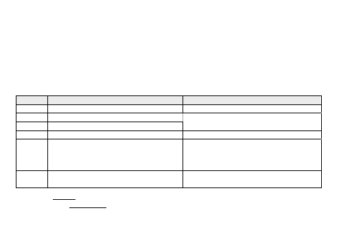
59
SERIAL CONFIGURATION
All models are fitted with 1 TTL serial channel for:
o
Copy card connection to upload/download parameters.
o
Serial communication with personal computer via RS-232/TTL conversion modules.
The TTL serial - referred to as COM1 - can be used for:
configuring parameters with the ParamManager or DeviceManager software using the Eliwell protocol
configuring parameters and monitoring with Televis Net software using the Eliwell or Modbus protocol PC
Interface connection modules are required.
configuring device parameters, states, and variables with the Modbus via the Modbus protocol
For selection of the protocol and setting of the device address, see the following table:
Parameter Description
Value
CF54
Select COM1 (TTL) protocol
0 = Eliwell
1= Modbus
CF55
Eliwell protocol controller address
CF56
Eliwell protocol controller family
0…14
CF63
Modbus protocol controller address
1…255
CF64
Modbus protocol Baudrate
0=1200 baud
1=2400 baud
2=4800 baud
3=9600 baud
4=19200 baud
5=38400 baud
6=58600 baud
7=115200 baud
CF65
Modbus protocol parity
1= EVEN
2= NONE
3= ODD
IMPORTANT: DO NOT supply power via TTL present on PC Interface 2150 to the EWCM4120-4150-4180 device.
To avoid errors, it is OBLIGATORY to cut the wire corresponding to 5Vdc of the 5-pole TTL connector, as illustrated
in the figure:
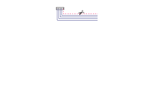
TTL
5V NOT FOR SUPPLY
5V
TTL CABLE
Copy card
The Copy Card is an accessory which, when connected to the TTL type serial port, allows quick programming of the
instrument parameters (upload and download of a parameter map to or from one or more instruments of the same
type). The operations are carried out via the following commands present in the CC folder, consent for the operation
is given by pressing the "set" key:
Fr-Format: This command is used to format the copy card, an operation which is necessary when the instrument is
being used for the first time or with other models which are not mutually compatible. Important: When the copy card
is formatted, all data is deleted. This operation cannot be cancelled.
UL-Upload: this command copies (uploads) the parameter values from the instrument to the copy card.
dL-Download: this command copies (downloads) the parameter values from the copy card to the instrument.
If the operation was completed successfully the word "yes" will be displayed, if not the label "Err" will appear. After
the download the instrument must be reset.
Download from reset: Connect the copy card to the switched off instrument. When the instrument is turned on, the
programming parameter values will automatically be loaded from the copy card to the instrument. After the lamp
test, the display shows the following labels for about 5 seconds: “dLY” if the operation is successful, “dLn” if not.
At the end of the operation, the instrument will switch to OFF status (if a digital input is set as on/off, at the end of
the download from reset the instrument will assume the state of the digital input)
60
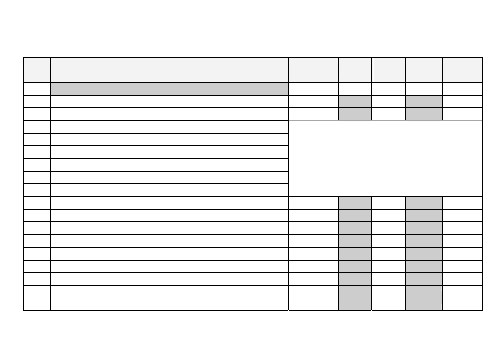
61
PARAMETERS LIST
Note: When a parameter is edited outside of the limits, the display flashes. To stop the flashing, press the UP/DOWN
keys once. NOTE: CFBP = °C/°F/Bar/Psi
Par. Description
Range
EWCM
4120
EWCM
4150
EWCM
4180
M.U.
CF Folder
CF02 Type of input analogue AI3
0…5
3
3
3
num
CF03 Type of input analogue AI4
0…5
3
3
3
num
CF04 Analogue input AI3 full scale value
CF05 Analogue input AI3 start of scale value
CF06 Analogue input AI4 full scale value
CF07 Analogue input AI4 start of scale value
Parameters CF04 … CF11 limit table
CF10 Analogue input AI3 differential
CF11 Analogue input AI4 differential
Parameters CF04 … CF11 limit table
CF14 Configuration of analogue input AI3
0…3
1
1
1
num
CF15 Configuration of analogue input AI4
0…3
0
0
2
num
CF16 Configuration of digital input DI1
-21…21
3
3
3
num
CF17 Configuration of digital input DI2
-21…21
4
4
4
num
CF18 Configuration of digital input DI3
-21…21
5
5
5
num
CF19 Configuration of digital input DI4
-21…21
6
6
6
num
CF20 Configuration of digital input DI5
-21…21
13
13
13
num
CF23 Configuration of analogue input AI1 when configured as
digital input
-21…21
1
0
1
num

62
CF24 Configuration of analogue input AI2 when configured as
digital input
-21…21
2
2
2
num
CF25 Configuration of analogue input AI3 when configured as
digital input
-21…21
0
0
0
num
CF26 Configuration of analogue input AI4 when configured as
digital input
-21…21
0
0
0
num
CF27 Type of output analogue AO3
0…2
-
0
0
num
CF30 Configuration of analogue output AO3
-24…26
-
0
25
num
CF33 Enable analogue TC output
0…1
1
-
-
num
CF34 Enabling analogue output AO1
0…1
1
0
0
num
CF35 Enabling analogue output AO2
0…1
-
0
0
num
CF36 Analogue TC output phase shift
0…90
27
-
-
num
CF37 Phase shift analogue output AO1
0…90
27
27
27
num
CF38 Phase shift analogue output AO2
0…90
-
27
27
num
CF39 Analogue TC output pulse length
5…40
10
-
-
num
CF40 Analogue output AO1 pulse length
5…40
10
10
10
num
CF41 Analogue output AO2 pulse length
5…40
-
10
10
num
CF42 Analogue TC output configuration
-24…26
25
-
-
num
CF43 Configuration of analogue output AO1
-24…26
25
0
0
num
CF44 Configuration of analogue output AO2
-24…26
-
0
0
num
CF45 Configuration of digital output DO1
-24…24
1
1
1
num
CF46 Configuration of digital output DO2
-24…24
2
2
2
num
CF47 Configuration of digital output DO3
-24…24
4
4
4
num
CF48 Configuration of digital output DO4
-24…24
3
3
3
num
CF49 Configuration of digital output DO5
-24…24
15
0
0
num
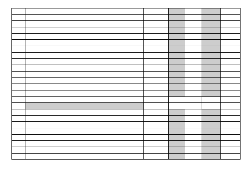
63
CF50 Configuration of digital output DO6
-24…24
-
15
15
num
CF51 Configuration of digital AO1 output
-24…24
0
0
0
num
CF52 Configuration of digital AO2 output
-24…24
-
0
0
num
CF54 Select COM1 protocol
0…1
0
0
0
num
CF55 Eliwell protocol controller address
0…14
0
0
0
num
CF56 Eliwell protocol controller family
0…14
0
0
0
num
CF63 Modbus protocol controller address
1…255
1
1
1
num
CF64 Modbus protocol Baudrate
0…7
3
3
3
num
CF65 Modbus protocol parity
1…3
1
1
1
num
CF66 Client code 1
0…255
0
0
0
num
CF67 Client code 2
0…255
0
0
0
num
CF68 Firmware version
0…999
0
0
0
num
CF71 Tab
0…999
1
5
2
num
CF72 RTC present
0…1
1
1
1
num
CF79 Firmware mask
0…999
0
0
0
num
UI Folder
UI00 Configuration of led1
0…32
1
1
1
num
UI01 Configuration of led2
0…32
2
2
2
num
UI02 Configuration of led3
0…32
3
3
3
num
UI03 Configuration of led4
0…32
4
4
4
num
UI04 Configuration of led5
0…32
0
0
0
num
UI05 Configuration of led6
0…32
0
0
0
num
UI06 Configuration of led7
0…32
0
0
0
num
UI07 Configuration of led8
0…32
25
0
25
num
64
UI08 Configuration of led9
0…32
27
0
27
num
UI09 Configuration of led10
0…32
28
0
28
num
UI10 Configuration of led11
0…32
29
0
29
num
UI12 Select main set point display
0…1
0
-
0
num
UI13 Select main display
0…6
2
2
2
num
UI20 Installer password
0…255
1
1
1
num
UI21 Manufacturer password
0…255
2
2
2
num
UI22 Unit of temperature measurement
0…1
0
0
0
num
UI23 Unit of pressure measurement
0…1
0
0
0
num
ST Folder
St01 Central/lateral set point
0…1
1
1
1
num
St02 Select Hot/cold operating modes
0…1
1
1
1
num
St03 Absolute/relative alarms
0…1
0
0
0
num
St04 Regulators configuration
0…3
1
1
1
num
CP Folder
CP00 Regulation setpoint
CP01…CP02 230
230
230
CFBP
CP01 Setpoint bottom limit
-999…CP02 -100
-100
-100
CFBP
CP02 Setpoint upper limit
CP01…9999 700
700
700
CFBP
CP03 Proportional band
0…9999
50
50
50
CFBP
CP04 Delta minimum cut-off
0…9999
20
20
20
CFBP
CP05 Delta saturation cut-off
0…9999
20
20
20
CFBP
CP06 Hysteresis minimum cut-off
0…9999
10
10
10
CFBP
CP07 Hysteresis saturation cut-off
0…9999
10
10
10
CFBP
CP08 Enable minimum cut-off
0…1
1
1
1
num
65
CP09 Enable saturation cut-off
0…1
1
1
1
num
CP10 Activation Policy
0…2
1
1
1
num
CP11 Enable/disable sequence of relays associated to compressor
power stages in the suction section
0…2
2
2
2
num
CP12 Compressor min. OFF-ON time
0…255
1
1
1
min
CP13 Compressor min. ON-ON time
0…255
1
1
1
min
CP14 Compressor min. ON-OFF time
0…255
15
15
15
secs
CP15 Interstep up time
0…255
30
30
30
secs
CP16 Interstep down time
0…255
10
10
10
secs
CP17 Maximum hours of use for compressor
0…6500
0
0
0
Hours*10
CP18 Minimum speed
0…100
20
20
20
%
CP19 Maximum speed
0…100
80
80
80
%
CP20 Saturation speed
0…100
100
100
100
%
CP21 Default power for non-allocated probe/probe error
0…100
0
0
0
%
CP22 Number of compressor steps per circuit
0…4
4
4
4
num
CP23 Number of compressor steps 1
1…4
1
1
1
num
CP24 Number of compressor steps 2
1…3
1
1
1
num
CP25 Number of compressor steps 3
1…2
1
1
1
num
Fn Folder
Fn00 Regulation setpoint
Fn01…Fn02 151
-
151
CFBP
Fn01 Setpoint bottom limit
-999…Fn02 -500
-
-500
CFBP
Fn02 Setpoint upper limit
Fn01…9999 999
-
999
CFBP
Fn03 Proportional band
0…9999
20
-
20
CFBP
Fn04 Delta minimum cut-off
0…9999
20
-
20
CFBP
Fn05 Delta saturation cut-off
0…9999
20
-
20
CFBP
66
Fn06 Hysteresis minimum cut-off
0…9999
10
-
10
CFBP
Fn07 Hysteresis saturation cut-off
0…9999
10
-
10
CFBP
Fn08 Enabling minimum cut-off
0…1
1
-
1
num
Fn09 Enabling saturation cut-off
0…1
1
-
1
num
Fn10 Compressor operation on request
0…1
0
-
1
num
Fn11 Enable fan rotation
0…1
0
-
0
num
Fn12 Mode for reaching maximum pick-up speed
0…1
0
-
0
num
Fn13 Fan pick-up time
0…255
2
-
5
secs
Fn14 Bypass cut-off time
0…255
80
-
80
secs
Fn15 Preventilation
0…255
0
-
0
secs
Fn16 Interstep up time
0…255
15
-
15
secs
Fn17 Interstep down time
0…255
5
-
5
secs
Fn18 Maximum time all fans can stay off
0…500
500
-
500
Hours
Fn19 Maximum hours of use for fan
0…6500
0
-
0
Hours*10
Fn20 Minimum speed
0…100
40
-
40
%
Fn21 Maximum silent speed
0…100
100
-
90
%
Fn22 Maximum speed
0…100
100
-
100
%
Fn23 Maximum pick-up speed
0…100
100
-
100
%
Fn24 Default power for non-allocated probe/probe error
0…100
100
-
100
%
Fn25 Number of fans per step for fan coil
-1…4
0
-
0
num
Fn26 Fan forcing time after maximum OFF time
0…54
10
-
10
min
Al Folder
AL00 Time interval for alarm event count
1…99
60
60
60
min
AL01 Number of inlet pressure switch events
0…33
0
0
0
num

67
AL02 Inlet pressure switch alarm bypass time
0…255
0
0
0
secs
AL03 Number of outlet pressure switch events
0…33
0
0
0
num
AL04 Outlet pressure switch alarm bypass time
0…255
0
0
0
secs
AL05 Number of inlet low analogue alarm events
0…33
0
0
0
num
AL06 Inlet low analogue alarm bypass time
0…255
0
0
0
secs
AL07 Number of inlet high analogue alarm events
0…33
0
0
0
num
AL08 Inlet high analogue alarm bypass time
0…255
0
0
0
secs
AL09 Number of outlet low analogue alarm events
0…33
0
0
0
num
AL10 Outlet low analogue alarm bypass time
0…255
0
0
0
secs
AL11 Number of outlet high analogue alarm events
0…33
0
0
0
num
AL12 Outlet high analogue alarm bypass time
0…255
0
0
0
secs
AL13 Number of compressor shut-down alarm events
0…33
0
0
0
num
AL14 Compressor shut-down alarms bypass time
0…255
0
0
0
secs
AL15 Number of fan thermal switch alarm events
0…33
0
-
0
num
AL16 Fan thermal switch alarms bypass time
0…255
0
-
0
secs
AL17 Inlet probe maximum alarm switch-on threshold
-999…9999 350
350
350
CFBP
1
AL18 Hysteresis for switching off inlet probe maximum alarm
0…9999
50
50
50
CFBP
1
AL19 Inlet probe minimum alarm switch-on threshold
-999…9999 160
160
160
CFBP
1
AL20 Hysteresis for switching off inlet probe minimum alarm
0…9999
50
50
50
CFBP
1
AL21 Outlet probe maximum alarm switch-on threshold
-999…9999 195
195
195
CFBP
2
AL22 Hysteresis for switching off outlet probe maximum alarm
0…9999
20
20
20
CFBP
2
AL23 Outlet probe minimum alarm switch-on threshold
-999…9999 134
134
134
CFBP
2
AL24 Hysteresis for switching off outlet probe minimum alarm
0…9999
20
20
20
CFBP
2
AL25 Maximum number of events in alarm log for alarm signal
0…99
0
0
0
num
68
1
* Display in decimals if M.U. °C/°F/Psi, in centimetres if Bar.
2
* Display in decimals if M.U. °C/°F/Bar, in units if Psi.
For determination of the UM and decimal point, see also parameters CP and Fn.
Parameters CF04 ..CF11 limits table
These limits depend on the measuring unit (parameters UI22 and UI23):
°C
°F
Bar
Psi
Par.
Min
Max
Min
Max
Min
Max
Min
Max
Min
Max
Min
Max
Hi
Lo
Hi
Lo
CF04
-
-
-
-
CF05 40.00
-
-
CF05 580.0
-
-
CF05
-
-
-
-
-5.00 CF04
-
-
-72.5 CF04
-
-
CF06
-
-
-
-
-
-
CF07 100.0
-
-
CF07 1450
CF07
-
-
-
-
-
-
-5.0
CF06
-
-
-72
CF06
CF08
-10.0 10.0 -18.0 18.0
-
-
-
-
-
-
-
-
CF09
-10.0 10.0 -18.0 18.0
-
-
-
-
-
-
-
-
CF10
-10.0 10.0 -18.0 18.0
-1.00
1.00
-
-
-14.5
14.5
-
-
CF11
-10.0 10.0 -18.0 18.0
-
-
-10.0
10.0
-
-
-145
145
Hi: High resolution; Lo: Low resolution;
WARNING The number of decimal points will therefore depend on the type of measuring unit and its resolution.
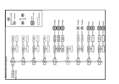
NAVIGATION MENU DIAGRAMS
69
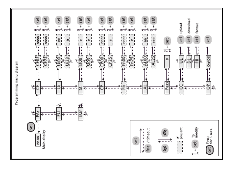
70
70
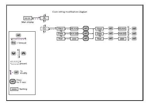
71

72
ACCESSORY PRODUCTS
The following Eliwell products may be used with the controller:
CF10xxxxxxxxx devices which enable motor control (fans, pumps...) with phase cutting and using a specific input
signal. Available in various models depending on the input signal (PWM or 4..20mA or 0..10V) and the pilotable
load (2A or 4A or 6A or 8A)
EXP211 device which enables control of an external resource using an open collector signal input;
DRV module for three-phase fan piloting;
Communication modules RS 232 TTL converter MW318934 (≤19200 err=0%, 38400 err=1%, ≥57600 err=infinite)
and BusAdapter (≤38400 err=0%, 57600 err>0, 115200 err=infinite)
TF411200 transformer for device power supply
Copy card CC0S00A00M000: enables the copying of parameter maps from instrument to copy card or vice-versa.
Power cabling COHV000000100: enables the connection of the device to loads
Signal cabling COLV000000100: enables the connection of the power supply, probes and digital inputs.
Temperature probes SNxxxxx: NTC probes available in various lengths and cap dimensions
Pressure probes TD2001xxx: pressure probes available in various models
Ratiometric transducers EWPA R 0/5V with: 0/10 bar (TD400010), 0/30 bar (TD400030) or 0/50 bar (TD400050)
DeviceManager 100 (DMP100x002000, where x = 1/2/3 - level)
ParamManager (SLP05XX000100) with PCInterface 2150 (PCI5A3000000)
73
TECHNICAL DATA
Mechanical characteristics
Front protection
IP65
Housing
PC + ABS UL94 - V0 plastic resin casing, polycarbonate screen, thermoplastic resin keys
Dimensions
front panel 76.4x35mm (+0.2mm), depth 67mm.
Mounting
panel mounting with 71x29mm (+0,2/-0,1mm) drilling template
Temperature
operating: -10°C … +60°C - storage: -20°C … +85°C
Ambient humidity
operating/storage: 10…90% RH (not condensing)
Electrical characteristics
Power supply
12V ±10% 50/60 Hz
Consumption 5VA
max
Insulation class
2 (in normal conditions, the instrument must NOT be accessible)
Display range
-999 … +9999 (on display with 4 digit)
Connections
TTL connector for connection to Copy-card or PC (via interface)
Input/Output characteristics
Num. Characteristics
2
Configurable as:
• NTC temperature sensor Semitec type 103AT (10kΩ / 25°C),
• voltage free digital input.
Analogue inputs (Configurable)
[AI1..AI4]
2
Configurable as:
• NTC temperature sensor Semitec type 103AT (10kΩ / 25°C),
• 4..20mA current input,
• 0..5V voltage input (21kΩ input impedance),
• 0..10V voltage input (21kΩ input impedance),
• voltage free digital input
.

74
Digital inputs
[DI1..DI5]
5 Type: voltage free with closing current for ground
Closing current for ground: 0.5 mA
4 EWCM4120:
relay 2A resistive 250V
Digital outputs 110Vac/230Vac
[DO1..DO4 e DO6]
5 EWCM4150 and EWCM4180:
relay 2A resistive 250V
Triac output*
[TC]
1 EWCM4120:
Triac 2A max 250V output
Low voltage digital output
[DO5]
1 Open collector, max current 35mA**
1 AO1 for model EWCM4120:
Max current 35mA** (min load of 600 Ω with 12V
c
)
Analogue outputs
(PWM/Open collector)
[AO1 and AO2]
2 AO1+AO2 for models EWCM4150 and EWCM4180:
Max current 35mA** (min load of 600 Ω with 12V
c
)
Low voltage analogue outputs
(0..10Vcc / 4..20mA)
[AO3]
1 EWCM4150 and EWCM4180:
For output 0…10V
c
, max 20mA a 10V
c
(min load resistance 500Ω).
For output 4…20mA max (max load resistance) 350 Ω
*Remote control switches downstream from the Triac are NOT permitted, since they have a “holding current”
(minimum current necessary to keep it turned on) above 50mA: cannot pilot loads, such as remote control switches,
which have a lower current.
** Outputs AO1, AO2 and DO5 will not activate at the same time with currents greater than 20mA

Eliwell Controls s.r.l.
Via dell’Industria, 15 • Zona Industriale Paludi • 32010 Pieve d’Alpago (BL) ITALY
Telephone +39 0437 986 111 • Facsimile +39 0437 989 066
Technical helpline +39 0437 986 300 • E-mail techsuppeliwell@invensyscontrols.com
www.eliwell.it
© Eliwell Controls s.r.l. 2009 All rights reserved.
Cod. 9MA10015
Rel. 09/09
EN
75
Wyszukiwarka
Podobne podstrony:
EWCM 4120 4180
4180
4150
4150
4150
EWCM 900
4120
4150
4180
4120
4180
4180
4180
więcej podobnych podstron