167
In This Chapter
9
Creating Work Features
In Autodesk
®
Mechanical Desktop
®
, work features are
special construction features that you use to place
geometry that would otherwise be very difficult to
position parametrically.
By constraining sketched and placed features to a work
feature, that is in turn constrained to your part, you can
easily control their location by changing the position of
the work feature.
This tutorial teaches you how to use work features to
control the position of sketched features. You learn
about each of these features as you work through the
tutorial.
■
Work planes
■
Work axes
■
Work points

168
|
Chapter 9
Creating Work Features
Key Terms
Term
Definition
nonparametric work
plane
A work plane fixed in location with respect to a part. If the part geometry is
parametrically changed, the work plane is unaffected.
parametrics
A solution method that uses the values of part parameters to determine the
geometric configuration of the part.
parametric work plane
A work plane associated with and dependent on the edges, faces, planes, vertices,
and axes of a part.
sketch plane
A temporary drawing surface that corresponds to a real plane on a feature. It is an
infinite plane with both X and Y axes on which you sketch or place a feature.
work axis
A parametric construction line created along the centerline of a cylindrical feature,
or sketched on the current sketch plane. A work axis can be used as the axis of
revolution for a revolved or swept feature, an array of features, to place a work
plane, and to locate new sketch geometry. It can be included in dimensions.
work feature
Planes, axes, and points used to place geometric features on an active part.
work plane
An infinite plane attached to a part. A work plane can be designated as a sketch
plane and can be included in a constraint or dimension scheme. Work planes can
be either parametric, or nonparametric.
work point
A parametric work feature used to position a hole, the center of an array, or any
other point for which there is no other geometric reference.
Basic Concepts of Work Features
|
169
Basic Concepts of Work Features
When you build a parametric part, you define how the part’s features are
associated. Changing one feature directly affects all the features related to it.
Work features are special construction features that help you define the rela-
tionships between the features on your part. They provide control when
placing sketches and features. Any changes to the position of a work feature
directly affect the placement of the sketches and features constrained to it.
You use work features to define
■
A plane to place sketches and features
■
A plane or edge to place parametric dimensions and constraints
■
An axis or point of rotation for revolved, swept, and array features
There are three types of work features: work planes, work axes, and work
points. In this tutorial, you learn the basics of creating and modifying each
of these work features.
Open the file w_feat.dwg in the desktop\tutorial folder.
NOTE
Back up the tutorial drawing files so you still have the original files if you
make a mistake. See “Backing up Tutorial Drawing Files” on page 40.
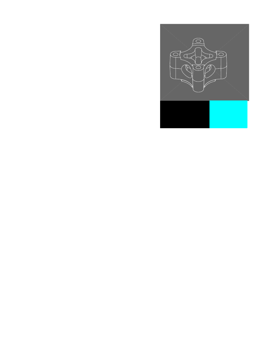
The drawing contains three simple parts.
Each part has a profile sketch associated with it. You create work features to
control the behavior of each of the sketches.
170
|
Chapter 9
Creating Work Features
Creating Work Planes
A work plane is an infinite plane that you attach to your part. It can be either
parametric or nonparametric. A work plane can also be used to define a sketch
plane for new geometry. To position a feature that does not lie on the same
plane as your base feature, you define a new plane and then create the feature.
If the plane is parametric, any changes to it affect the position of the feature.
Work planes are defined using two modifiers. The modifiers determine how
the plane will be oriented. By selecting the right modifiers, you can create a
work plane wherever you need a plane to place geometry.
Parametric work planes can be created by specifying edges, axes, or vertices,
and defining whether the plane is normal, parallel, or tangent to selected
geometry. Nonparametric work planes can be created on the current coordi-
nate system (UCS), or on any of the three planes of the World Coordinate
System (WCS).
For more information about creating work planes, see
AMWORKPLN
in the
online Command Reference.
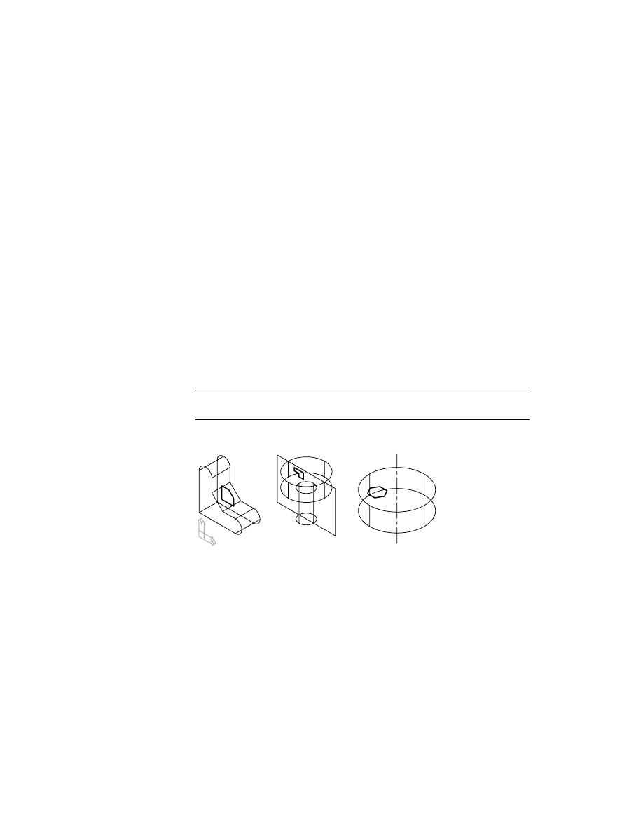
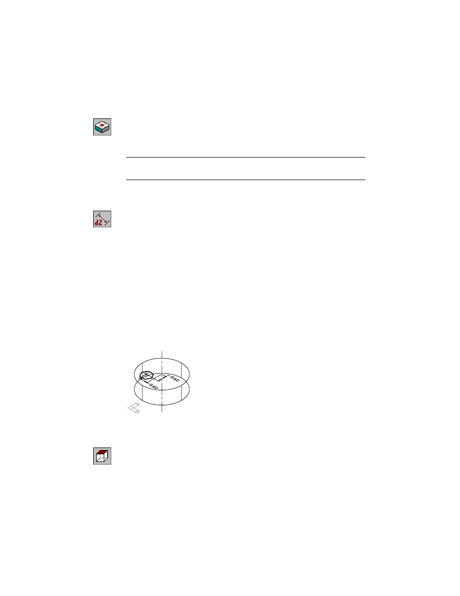
PART1_1 contains an extrusion with a profile constrained to its back face.
NOTE
For clarity, the parametric dimensions are not shown.
In this tutorial, you use this profile to cut material from the part. By extrud-
ing the profile to a work plane, you can easily control the depth of the extru-
sion by changing the position of the plane.
Creating Work Planes
|
171
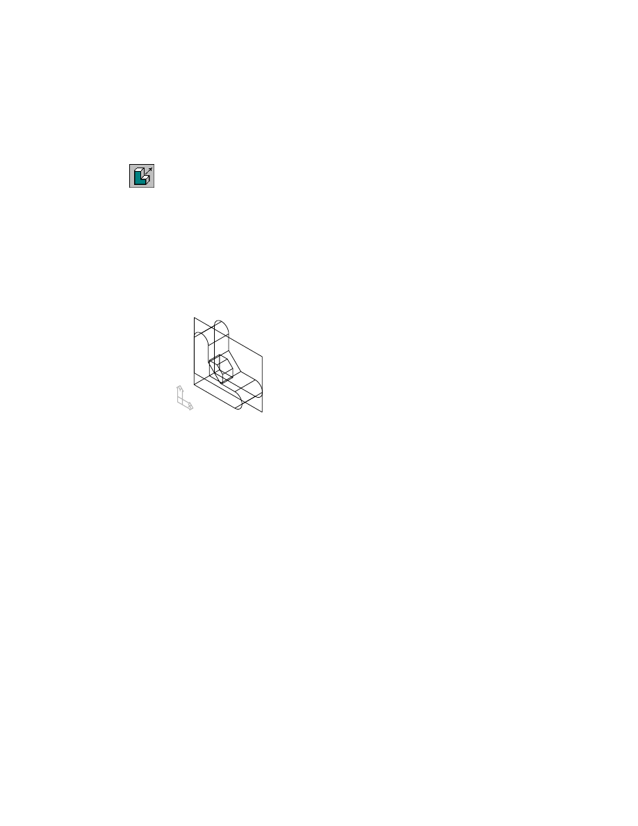
First, you create a work plane through the midplane of the part and extrude
the profile to it. Later, you edit the position of the work plane to modify the
depth of the new extrusion.
Activate PART1_1 and use ZOOM to position it on your screen.
Browser
Double-click PART1_1. Now right-click PART1_1 and
choose Zoom to.
To create a work plane
1
Use
AMWORKPLN
to create a work plane through the midplane of PART1_1
.
Context Menu
In the graphics area, right-click and choose Sketched &
Work Features ➤ Work Plane.
2
In the Work Plane dialog box, specify:
1st Modifier:
Planar Parallel
2nd Modifier:
Offset
Offset:
Enter .5
Choose OK.
3
Continue on the command line.
Select work plane, planar face or [worldXy/worldYz/worldZx/Ucs]:
Specify the front face
Enter an option [Next/Accept] <Accept>:
Enter n to cycle to the front face or press
ENTER
Enter an option [Flip/Accept] <Accept>:
Enter f to point direction arrows into the part
Enter an option [Flip/Accept] <Accept>:
Press
ENTER
Plane = Parametric
Select edge to align X axis or [Flip/Rotate/Origin] <accept>:
Press
ENTER
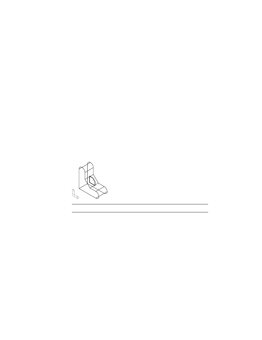
A work plane now bisects the part.
Next, extrude the profile to the work plane.
work plane
172
|
Chapter 9
Creating Work Features
To extrude a profile to a plane
1
Use
AMEXTRUDE
to extrude the profile.
Context Menu
In the graphics area, right-click and choose Sketched &
Work Features ➤ Extrude.
2
In the Extrusion dialog box, specify the following:
Operation:
Cut
Termination:
Plane
Choose OK to exit the dialog box.
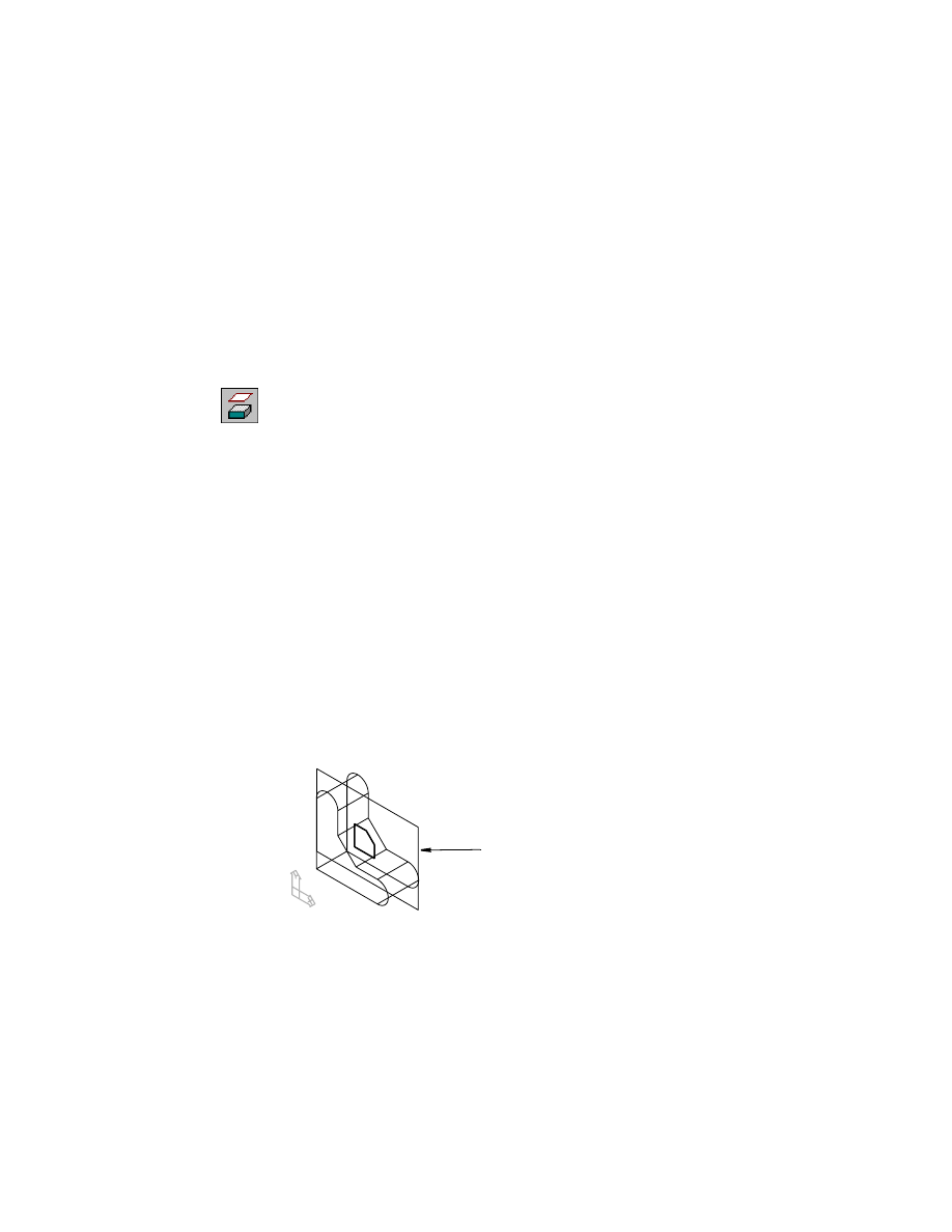
3
Continue on the command line.
Select face or work plane:
Specify the work plane
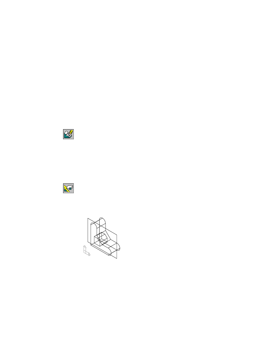
The profile is extruded to the work plane.
Now edit the location of the work plane to control the depth of the extrusion
you just created.
Editing Work Planes
|
173
Editing Work Planes
Because a nonparametric work plane is static, any features constrained to it
are restricted to the original plane. If you change the position or orientation
of your part, the features remain associated with the work plane and your
part could fail to update.
Whenever possible, locate your features on parametric work planes. When
you change the location of a parametric work plane, you change the position
of any features created on it or constrained to it.
To modify the position of a work plane
1
Use
AMEDITFEAT
to reposition the work plane, responding to the prompts.
Context Menu
In the graphics area, right-click and choose Edit Features
➤ Edit.
Enter an option [Sketch/surfCut/Toolbody/select Feature]
<selectFeature>:
Press
ENTER
Select feature:
Specify the work plane
Select object:
Specify the 0.5 dimension
Enter dimension value <.5>:
Enter .15
Select object:
Press
ENTER
2
Use
AMUPDATE
to update the part, responding to the prompt.
Context Menu
In the graphics area, right-click and choose Update Part.
Enter an option [active Part/aLl parts] <active Part>:
Press
ENTER
If you use the Browser, the prompt is not displayed.
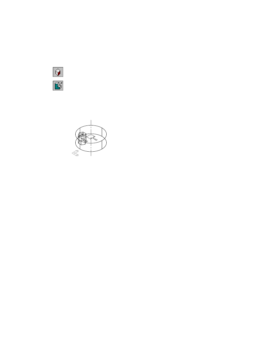
Your part should look like this.
Save your file.
174
|
Chapter 9
Creating Work Features
Creating Work Axes
A work axis is a parametric construction line used as the axis of revolution
for a revolved or swept feature, or an array of features; it is also used to place
a work plane, and to locate new sketch geometry. You can create a work axis
through the center of a cylindrical edge, or draw it on the current sketch
plane by specifying any two points.
PART2 contains a simple revolved feature, a work plane, and a partially con-
strained profile. You create a work axis through the center of the part. Then
you constrain the profile to the work axis so you can cut material from the
base feature.
NOTE
For clarity, the parametric dimensions are not shown.
Activate PART2 and use ZOOM to position it on your screen.
Browser
Double-click PART2_1. Now right-click PART2_1 and
choose Zoom to.
To create a work axis
1
Use
AMWORKAXIS
to create a work axis, responding to the prompt.
Context Menu
In the graphics area, right-click and choose Sketched &
Work Features ➤ Work Axis.
Select cylinder, cone or torus [Sketch]:
Select a cylindrical edge
Because the work axis is created through the center of the part, no constraints
are necessary.
Creating Work Axes
|
175
Next, constrain the profile to the new work axis and create a revolved feature
from it.
Depending on your drawing, your default dimension values may differ from
those in this exercise.
To constrain and revolve a profile
1
Use
AMPARDIM
to constrain the profile to the work axis. Add two dimensions,
responding to the prompts.
Context Menu
In the graphics area, right-click and choose Dimensioning
➤ New Dimension.
Select first object:
Specify the right edge of the profile (1)
Select second object or place dimension:
Specify the work axis (2)
Specify dimension placement:
Place the dimension (3)
Enter dimension value or [Undo/Hor/Ver/Align/Par/aNgle/Ord/Diameter/pLace]
<0.8324>:
Enter h to force a horizontal dimension
Enter dimension value or [Undo/Hor/Ver/Align/Par/aNgle/Ord/Diameter/pLace]
<0.1671>:
Enter 0
Solved underconstrained sketch requiring 1 dimensions or constraints.
Select first object:
Specify the top edge of the profile (4)
Select second object or place dimension:
Specify the top edge of the part (5)
Specify dimension placement:
Place the vertical dimension (6)
Enter dimension value or [Undo/Hor/Ver/Align/Par/aNgle/Ord/Diameter/pLace]
<0.1333>:
Enter 0
Solved fully constrained sketch.
Select first object:
Press
ENTER
work axis
3
2
1
5
6
4
176
|
Chapter 9
Creating Work Features
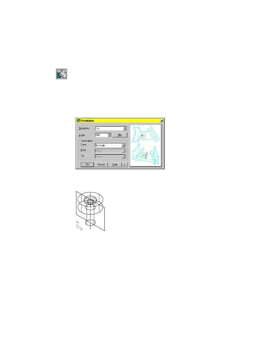
2
Use
AMREVOLVE
to revolve a feature from the profile, responding to the
prompt.
Context Menu
In the graphics area, right-click and choose Sketched &
Work Features ➤ Revolve.
Select revolution axis:
Select the work axis
3
In the Revolution dialog box, specify:
Operation:
Cut
Angle:
Enter 360
Termination:
By Angle
Choose OK to exit the dialog box.
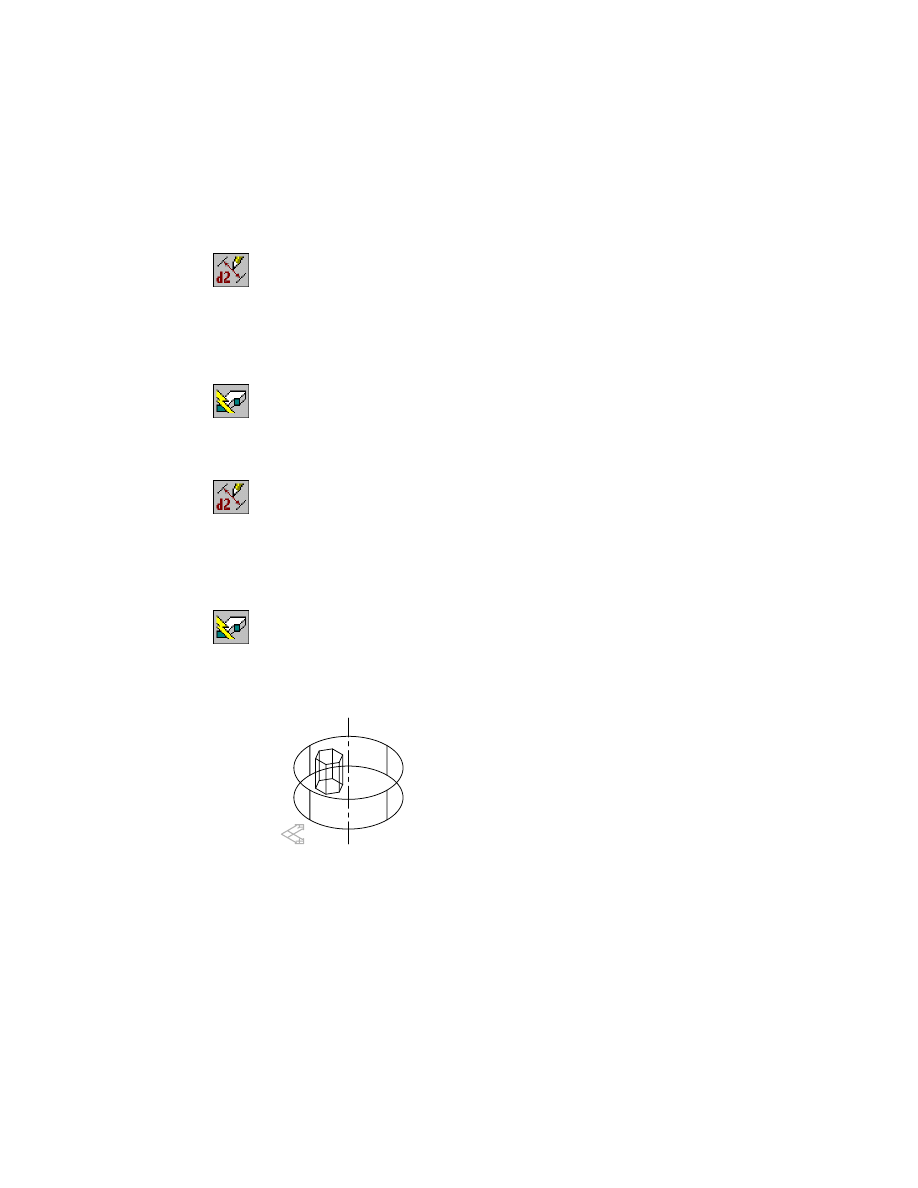
Your drawing should look like this.
Save your file.
Editing Work Axes
|
177
Editing Work Axes
Work axes are parametric, so any changes to the parameters controlling a
work axis affect the location of features constrained to it.
In this exercise, the work axis was created through the center of a cylindrical
object and cannot be repositioned. But by changing one of the dimensions
that constrains the profile to the axis, the revolved feature changes.
To modify the revolved feature, you change the horizontal dimension con-
straining the profile to the work axis. In this exercise, because the value of
the dimension is 0, modifying it forces the profile in the wrong direction. To
relocate the profile correctly, erase the dimension, move the profile slightly,
and then add a new horizontal dimension.
To reposition a profile constrained to a work axis
1
Edit the revolved feature with the Browser.
Browser
Right-click Revolution Angle1 and choose Edit Sketch.
2
Use
ERASE
to erase the 0.00 dimension constraining the profile to the work
axis.
Context Menu
In the graphics area, right-click and choose 2D Sketching
➤ Erase.
3
Use
MOVE
to move the profile and its dimensions, following the prompts.
Context Menu
In the graphics area, right-click and choose 2D Sketching
➤ Move.
Select objects:
Enter w
Specify first corner:
Specify a point above and left of the 0.15 dimension
Specify opposite corner:
Specify a point below and right of the 0.30 dimension
11 found
Select objects:
Press
ENTER
Specify base point or displacement:
Specify any point
Specify second point of displacement or <use first point as displacement>:
Specify a point to the left of the base point
NOTE
Press F8 to turn on orthographic mode before you specify the base and
second points.
178
|
Chapter 9
Creating Work Features
4
Use
AMPARDIM
to create a new parametric dimension, following the
prompts.
Context Menu
In the graphics area, right-click and choose Dimensioning
➤ New Dimension.
Select first object:
Specify the right edge of the profile
Select second object or place dimension:
Specify the work axis
Specify dimension placement:
Place the dimension
Enter dimension value or [Undo/Hor/Ver/Align/Par/aNgle/Ord/Diameter/pLace]
<0.4347>:
Verify that the dimension is horizontal, then enter .15
Solved fully constrained sketch.
Select first object:
Press
ENTER
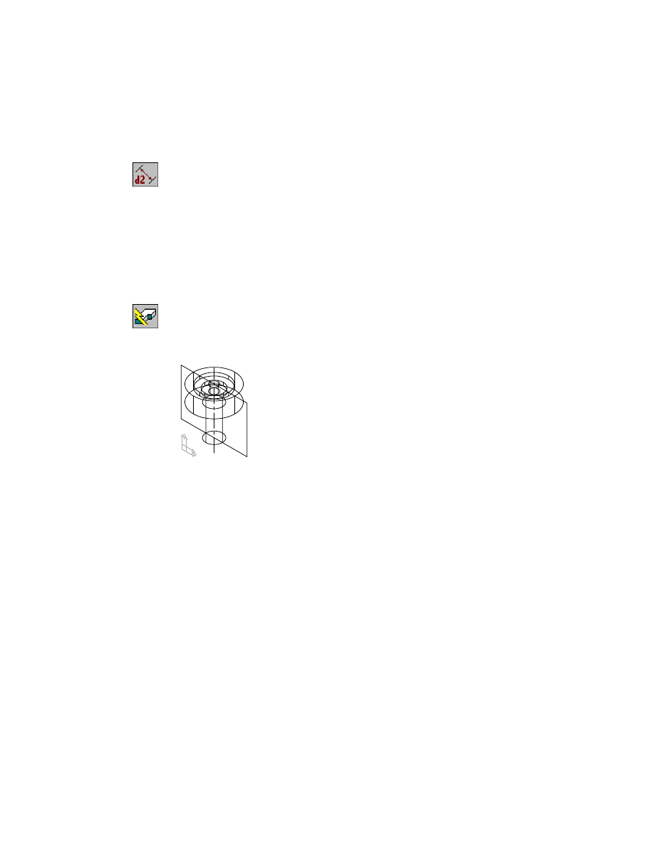
5
Use
AMUPDATE
to update the part, responding to the prompt.
Context Menu
In the graphics area, right-click and choose Update Part.
Enter an option [active Part/aLl parts] <active Part>:
Press
ENTER
Your drawing should look like this.
Save your file.
Creating Work Points
|
179
Creating Work Points
A work point is a parametric point for positioning features that cannot easily
be located on a part. By constraining a feature to a work point and then con-
straining the work point to the part, you control the position of the feature.
Use work points to
■
Position sketched features
■
Create centers for polar arrays
■
Place surface cut features
■
Place holes when concentric cylindrical edges, or two planar edges, are not
available
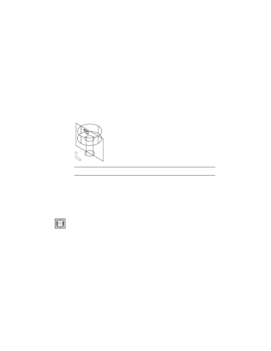
PART3 contains a simple cylindrical extrusion with a work axis at its center,
and a sketch on its top face.
You place a work point on the sketch plane and profile the sketch. Then, you
constrain the profile to the work point, and the work point to the work axis.
Activate PART3, and use ZOOM to position it on your screen.
Browser
Double-click PART3_1. Then right-click PART3_1 and
choose Zoom to.
180
|
Chapter 9
Creating Work Features
To create and constrain a work point
1
Use AMWORKPT to create a work point, responding to the prompt.
Context Menu
In the graphics area, right-click and choose Sketched &
Work Features ➤ Work Point.
Specify the location of the workpoint:
Specify a point near the center of the sketch
NOTE
You may prefer to turn OSNAP off before you create and constrain the
work point. Click the OSNAP button at the bottom of your screen.
2
Use
AMPARDIM
to constrain the work point to the work axis, following the
prompts.
Context Menu
In the graphics area, right-click and choose Dimensioning
➤ New Dimension.
Select first object:
Specify the work point
Select second object or place dimension:
Specify the work axis
Specify dimension placement:
Place the dimension
Enter dimension value or [Undo/Hor/Ver/Align/Par/aNgle/Ord/Diameter/pLace]
<0.5890>:
Verify the dimension is horizontal and enter .6
Solved underconstrained sketch requiring 1 dimensions or constraints.
Select first object:
Specify the work point
Select second object or place dimension:
Specify the work axis
Specify dimension placement:
Place the dimension
Enter dimension value or [Undo/Hor/Ver/Align/Par/aNgle/Ord/Diameter/pLace]
<0.6130>:
Verify the dimension is vertical and enter .6
Solved fully constrained sketch.
Select first object:
Press
ENTER
Solve the sketch and constrain it to a work point.
Change to a top view of your part.
Desktop Menu
View ➤ 3D Views ➤ Top
Creating Work Points
|
181
To solve a sketch and constrain it to a work point
1
Use
AMPROFILE
to solve the sketch, responding to the prompts.
Context Menu
In the graphics area, right-click and choose Sketch Solving
➤ Profile.
Select objects for sketch:
Specify the polygon sketch
Select objects for sketch:
Press
ENTER
Solved underconstrained sketch requiring 8 dimensions or constraints.
NOTE
Although the polygon is a single object, you cannot use Single Profile
to solve it because it was not the last object created.
The profile requires eight constraints: six to solve it, and two to constrain it
to the work point.
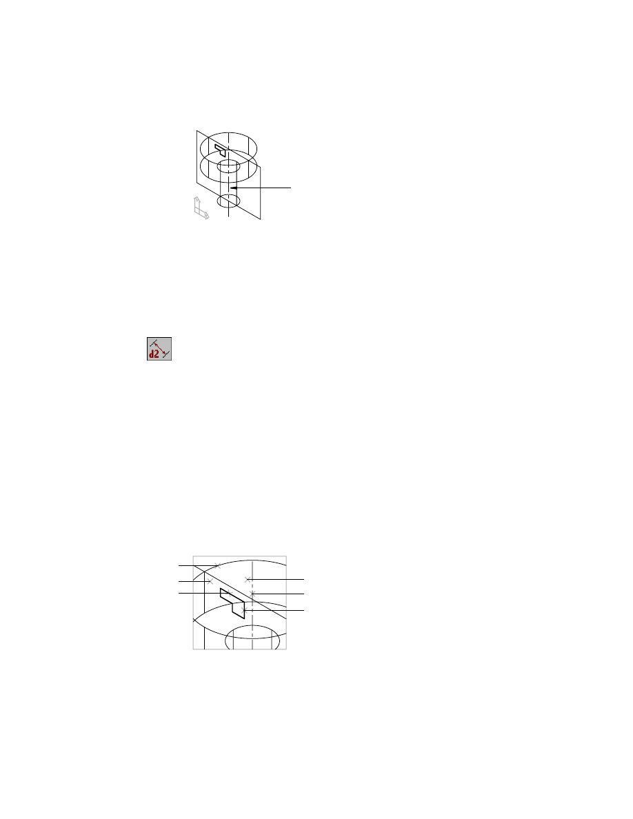
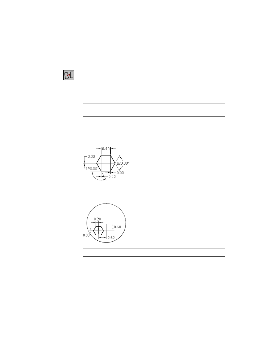
2
Zoom in to the profile and constrain it using the dimensions in the following
illustration.
You could also use Equal Length constraints on the line segments to reduce
the number of dimensions required.
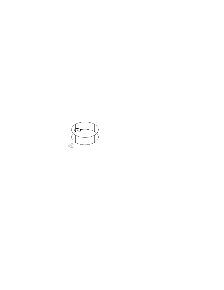
3
Constrain the profile to the work point as in the following illustration.
NOTE
For clarity, the dimensions of the profile are not shown.
The profile is now fully constrained. Next, you create an extrusion to cut
material from the base feature.
182
|
Chapter 9
Creating Work Features
To extrude a feature through a part
1
Change to an isometric view.
Desktop Menu
View ➤ 3D Views ➤ Front Right Isometric
2
Use
AMEXTRUDE
to extrude the profile through the part.
Context Menu
In the graphics area, right-click and choose Sketched &
Work Features ➤ Extrude.
In the Extrusion dialog box, specify:
Operation:
Cut
Termination:
Through
Choose OK.
The dimensions controlling the work point are still visible because the work
point has not been consumed by a feature.
Save your file.
Editing Work Points
Next, to relocate the extrusion you change the dimensions constraining the
work point to the work axis. The extrusion and the work point are paramet-
rically associated; any change to the position of the work point causes the
extrusion to move.
Editing Work Points
|
183
To edit a work point
1
Use
AMMODDIM
to modify the vertical sketch dimension controlling the
work point, responding to the prompts.
Context Menu
In the graphics area, right-click and choose Dimensioning
➤ Edit Dimension.
Select dimension to change:
Specify the vertical dimension
New value for dimension <0.6000>:
Enter 0
Solved fully constrained sketch.
2
Use
AMUPDATE
to update the part, responding to the prompt.
Context Menu
In the graphics area, right-click and choose Update Part.
Enter an option [active Part/aLl parts] <active Part>:
Press
ENTER
3
Use
AMMODDIM
to modify the horizontal sketch dimension controlling the
work point, responding to the prompts.
Context Menu
In the graphics area, right-click and choose Dimensioning
➤ Edit Dimension.
Select dimension to change:
Specify the horizontal dimension
New value for dimension <0.6000>:
Enter .75
Solved fully constrained sketch.
4
Update the part, responding to the prompt.
Context Menu
In the graphics area, right-click and choose Update Part.
Enter an option [active Part/aLl parts] <active Part>:
Press
ENTER
5
Turn off the visibility of the work point and its dimensions.
Browser
Right-click WorkPoint1 and choose Visible.
Save your file.
You learn more about creating work features as you go through the rest of the
tutorials in this book.

184
Wyszukiwarka
Podobne podstrony:
ch9 hematology
M 5190 Long dress with a contrast finishing work
policy work dev
120222160803 english at work episode 2
121024104303 bbc english at work episode 37
23 299 318 Optimizing Microstructure for High Toughness Cold Work Steels
Atari 8 Bit Demopac 7 Some Special Features
features
46 643 656 Vacuum HT of Hot Work Steel
130107151016 bbc english at work episode 48 final
Hollandus J I A Work of Saturn
E in T features & nescessity
ch9
Knockdown Work Support
checklist asphalt work
Work to live or live to work[1]
CE Specific features
więcej podobnych podstron