Tools and Working Facilities
REF•1
Introduction
A selection of good tools is a fundamental
requirement for anyone contemplating the
maintenance and repair of a motor vehicle.
For the owner who does not possess any,
their purchase will prove a considerable
expense, offsetting some of the savings made
by doing-it-yourself. However, provided that
the tools purchased meet the relevant national
safety standards and are of good quality, they
will last for many years and prove an
extremely worthwhile investment.
To help the average owner to decide which
tools are needed to carry out the various tasks
detailed in this manual, we have compiled
three lists of tools under the following
headings: Maintenance and minor repair,
Repair and overhaul, and Special. Newcomers
to practical mechanics should start off with
the Maintenance and minor repair tool kit, and
confine themselves to the simpler jobs around
the vehicle. Then, as confidence and
experience grow, more difficult tasks can be
undertaken, with extra tools being purchased
as, and when, they are needed. In this way, a
Maintenance and minor repair tool kit can be
built up into a Repair and overhaul tool kit over
a considerable period of time, without any
major cash outlays. The experienced do-it-
yourselfer will have a tool kit good enough for
most repair and overhaul procedures, and will
add tools from the Special category when it is
felt that the expense is justified by the amount
of use to which these tools will be put.
Maintenance and minor repair
tool kit
The tools given in this list should be
considered as a minimum requirement if
routine maintenance, servicing and minor
repair operations are to be undertaken. We
recommend the purchase of combination
spanners (ring one end, open-ended the
other); although more expensive than open-
ended ones, they do give the advantages of
both types of spanner.
• Combination spanners:
Metric-8, 9, 10, 11, 12, 13, 14, 15, 16, 17,
19, 21, 22, 24 & 26 mm
• Adjustable spanner - 35 mm jaw (approx)
• Engine sump/gearbox drain plug key
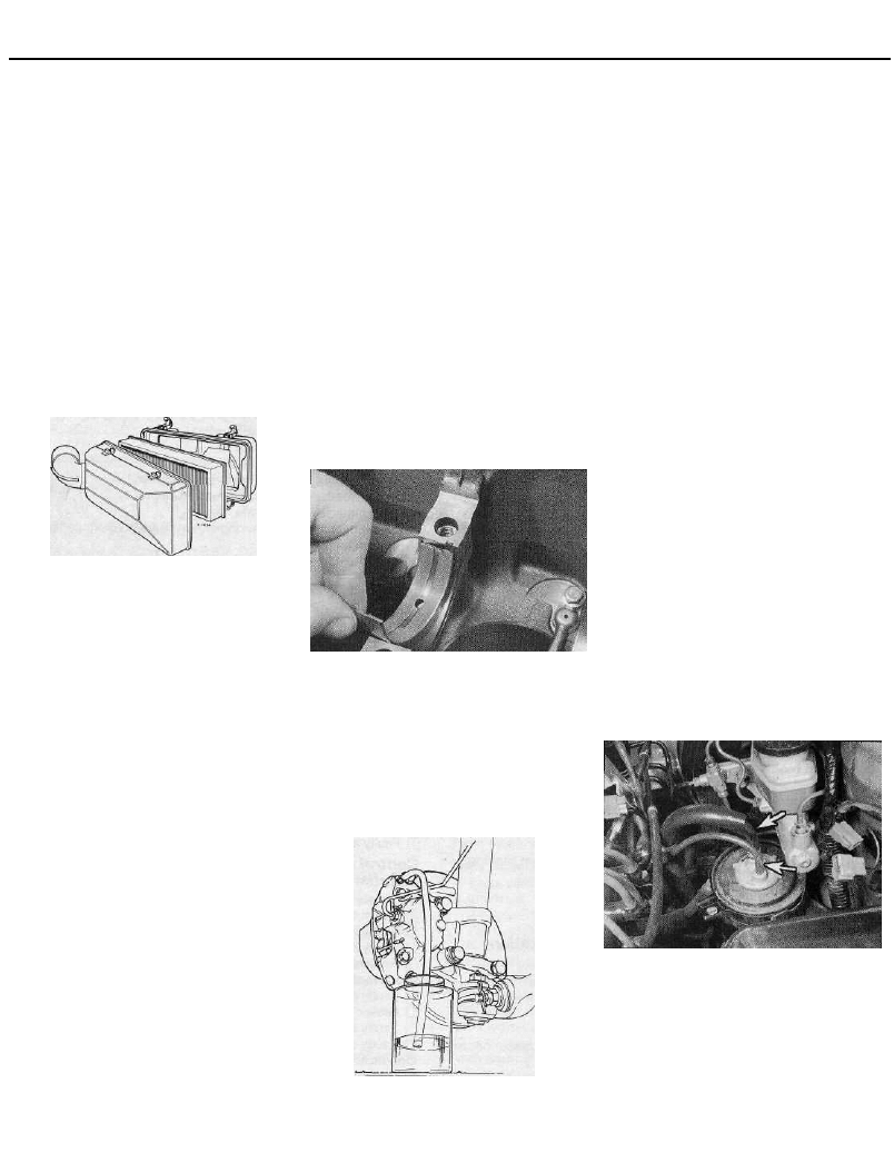
• Set of feeler gauges
• Brake bleed nipple spanner
• Screwdrivers:
Flat blade - approx 100 mm long x
6 mm dia
Cross blade - approx 100 mm long x
6 mm dia
• Combination pliers
• Hacksaw (junior)
• Tyre pump
• Tyre pressure gauge
• Oilcan
• Oil filter removal tool
• Fine emery cloth
• Wire brush (small)
• Funnel (medium size)
Repair and overhaul tool kit
These tools are virtually essential for
anyone undertaking any major repairs to a
motor vehicle, and are additional to those
given in the Maintenance and minor repair list.
Included in this list is a comprehensive set of
sockets. Although these are expensive, they
will be found invaluable as they are so
versatile - particularly if various drives are
included in the set. We recommend the half-
inch square-drive type, as this can be used
with most proprietary torque wrenches. If you
cannot afford a socket set, even bought
piecemeal, then inexpensive tubular box
spanners are a useful alternative.
The tools in this list will occasionally need to
be supplemented by tools from the Special
list:
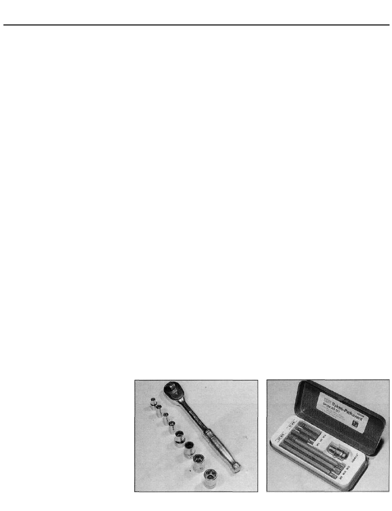
• Sockets (or box spanners) to cover range in
previous list
• Reversible ratchet drive (for use with
sockets) (see illustration)
• Extension piece, 250 mm (for use with
sockets)
• Universal joint (for use with sockets)
• Torque wrench (for use with sockets)
• Self-locking grips
• Ball pein hammer
• Soft-faced mallet (plastic/aluminium or
rubber)
• Screwdrivers:
Flat blade - long & sturdy, short (chubby),
and narrow (electrician's) types
Cross blade - Long & sturdy, and short
(chubby) types
• Pliers:
Long-nosed
Side cutters (electrician's)
Circlip (internal and external)
• Cold chisel - 25 mm
• Scriber
• Scraper
• Centre-punch
• Pin punch
• Hacksaw
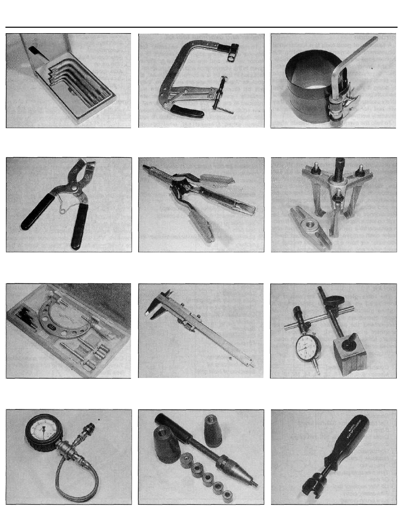
• Brake hose clamp
• Brake bleeding kit
• Selection of twist drills
• Steel rule/straight-edge
• Allen keys (inc. splined/Torx type) (see
illustrations)
• Selection of files
• Wire brush
• Axle stands
• Jack (strong trolley or hydraulic type)
• Light with extension lead
Special tools
The tools in this list are those which are not
used regularly, are expensive to buy, or which
need to be used in accordance with their
manufacturers' instructions. Unless relatively
difficult mechanical jobs are undertaken
frequently, it will not be economic to buy
many of these tools. Where this is the case,
you could consider clubbing together with
friends (or joining a motorists' club) to make a
joint purchase, or borrowing the tools against
a deposit from a local garage or tool hire
specialist. It is worth noting that many of the
larger DIY superstores now carry a large range
of special tools for hire at modest rates.
The following list contains only those tools
and instruments freely available to the public,
and not those special tools produced by the
vehicle manufacturer specifically for its dealer
network. You will find occasional references
to these manufacturers' special tools in the
text of this manual. Generally, an alternative
method of doing the job without the vehicle
manufacturers' special tool is given. However,
sometimes there is no alternative to using
them. Where this is the case and the relevant
tool cannot be bought or borrowed, you will
have to entrust the work to a franchised
garage.
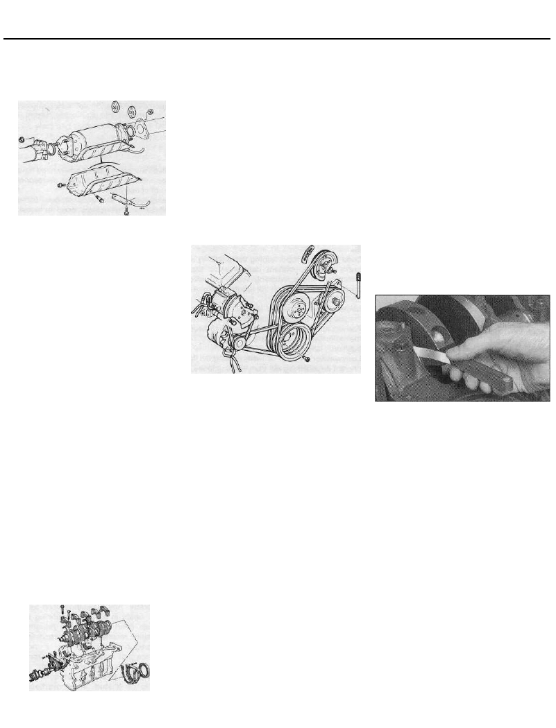
• Valve spring compressor (see illustration)
• Valve grinding tool
• Piston ring compressor (see illustration)
• Piston ring removal/installation tool (see
illustration)
• Cylinder bore hone (see illustration)
• Balljoint separator
• Coil spring compressors (where applicable)
• Two/three-legged hub and bearing puller
(see illustration)
Sockets and reversible ratchet drive
Spline bit set
REF•2
Tools and Working Facilities
Spline key set
Valve spring compressor
Piston ring compressor
Piston ring removal/installation tool
Cylinder bore hone
Three-legged hub and bearing puller
Micrometer set
Vernier calipers
Dial test indicator and magnetic stand
Compression testing gauge
Clutch plate alignment set
Brake shoe steady spring cup removal tool
Tools and Working Facilities
REF•3
• Impact screwdriver
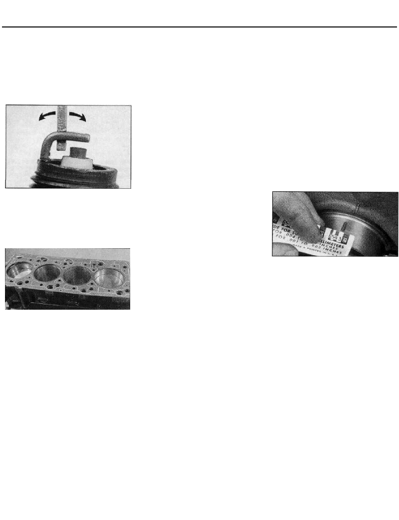
• Micrometer and/or vernier calipers (see
illustrations)
• Dial gauge (see illustration)
• Tachometer
• Universal electrical multi-meter
• Cylinder compression gauge
(see illustration)
• Clutch plate alignment set (see illustration)
• Brake shoe steady spring cup removal tool
(see illustration)
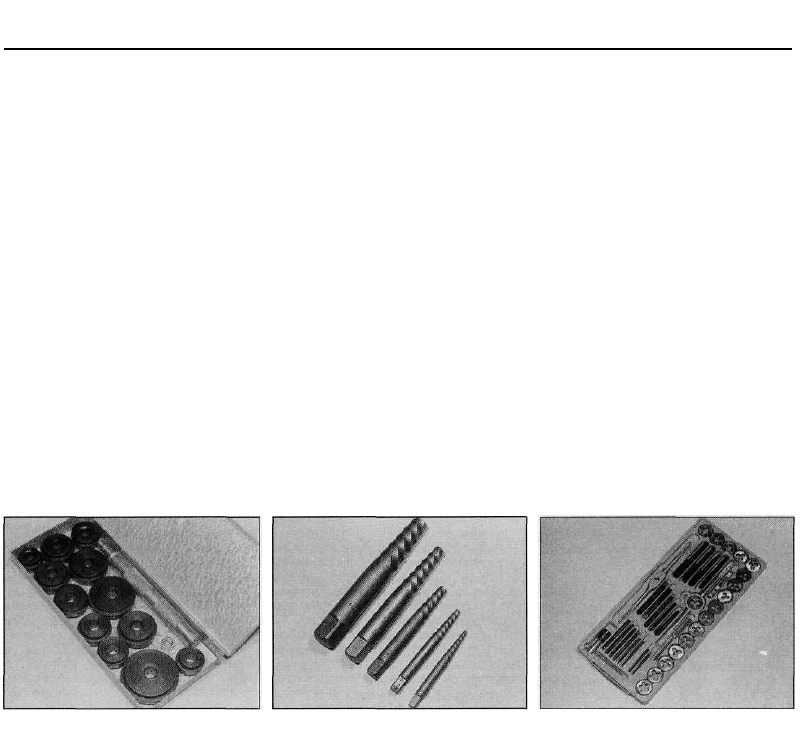
• Bush and bearing removal/installation set
(see illustration)
• Stud extractors (see illustration)
• Tap and die set (see illustration)
• Lifting tackle
• Trolley jack
Buying tools
For practically all tools, a tool factor is the
best source, since he will have a very
comprehensive range compared with the
average garage or accessory shop. Having
said that, accessory shops often offer
excellent quality tools at discount prices, so it
pays to shop around.
Remember, you don't have to buy the most
expensive items on the shelf, but it is always
advisable to steer clear of the very cheap
tools. There are plenty of good tools around at
reasonable prices, but always aim to purchase
items which meet the relevant national safety
standards. If in doubt, ask the proprietor or
manager of the shop for advice before making
a purchase.
Care and maintenance of tools
Having purchased a reasonable tool kit, it is
necessary to keep the tools in a clean and
serviceable condition. After use, always wipe
off any dirt, grease and metal particles using a
clean, dry cloth, before putting the tools away.
Never leave them lying around after they have
been used. A simple tool rack on the garage
or workshop wall for items such as
screwdrivers and pliers is a good idea. Store
all normal spanners and sockets in a metal
box. Any measuring instruments, gauges,
meters, etc, must be carefully stored where
they cannot be damaged or become rusty.
Take a little care when tools are used.
Hammer heads inevitably become marked,
and screwdrivers lose the keen edge on their
blades from time to time. A little timely
attention with emery cloth or a file will soon
restore items like this to a good serviceable
finish.
Working facilities
Not to be forgotten when discussing tools is
the workshop itself. If anything more than
routine maintenance is to be carried out, some
form of suitable working area becomes
essential.
It is appreciated that many an owner-
mechanic is forced by circumstances to
remove an engine or similar item without the
benefit of a garage or workshop. Having done
this, any repairs should always be done under
the cover of a roof.
Wherever possible, any dismantling should
be done on a clean, flat workbench or table at
a suitable working height.
Any workbench needs a vice; one with a
jaw opening of 100 mm is suitable for most
jobs. As mentioned previously, some clean
dry storage space is also required for tools, as
well as for any lubricants, cleaning fluids,
touch-up paints and so on, which become
necessary.
Another item which may be required, and
which has a much more general usage, is an
electric drill with a chuck capacity of at least 8
mm. This, together with a good range of twist
drills, is virtually essential for fitting
accessories.
Last, but not least, always keep a supply of
old newspapers and clean, lint-free rags
available, and try to keep any working area as
clean as possible.
Bush and bearing removal/installation set
Stud extractor set
Tap and die set

REF•4
General Repair Procedures
Whenever servicing, repair or overhaul work
is carried out on the car or its components, it
is necessary to observe the following
procedures and instructions. This will assist in
carrying out the operation efficiently and to a
professional standard of workmanship.
Joint mating faces and gaskets
When separating components at their
mating faces, never insert screwdrivers or
similar implements into the joint between the
faces in order to prise them apart. This can
cause severe damage which results in oil
leaks, coolant leaks, etc upon reassembly.
Separation is usually achieved by tapping
along the joint with a soft-faced hammer in
order to break the seal. However, note that
this method may not be suitable where
dowels are used for component location.
Where a gasket is used between the mating
faces of two components, ensure that it is
renewed on reassembly, and fit it dry unless
otherwise stated in the repair procedure.
Make sure that the mating faces are clean and
dry, with all traces of old gasket removed.
When cleaning a joint face, use a tool which is
not likely to score or damage the face, and
remove any burrs or nicks with an oilstone or
fine file.
Make sure that tapped holes are cleaned
with a pipe cleaner, and keep them free of
jointing compound, if this is being used,
unless specifically instructed otherwise.
Ensure that all orifices, channels or pipes
are clear, and blow through them, preferably
using compressed air.
Oil seals
Oil seals can be removed by levering them
out with a wide flat-bladed screwdriver or
similar implement. Alternatively, a number of
self-tapping screws may be screwed into the
seal, and these used as a purchase for pliers
or some similar device in order to pull the seal
free.
Whenever an oil seal is removed from its
working location, either individually or as part
of an assembly, it should be renewed.
The very fine sealing lip of the seal is easily
damaged, and will not seal if the surface it
contacts is not completely clean and free from
scratches, nicks or grooves.
Protect the lips of the seal from any surface
which may damage them in the course of
fitting. Use tape or a conical sleeve where
possible. Lubricate the seal lips with oil before
fitting and, on dual-lipped seals, fill the space
between the lips with grease.
Unless otherwise stated, oil seals must be
fitted with their sealing lips toward the
lubricant to be sealed.
Use a tubular drift or block of wood of the
appropriate size to install the seal and, if the
seal housing is shouldered, drive the seal
down to the shoulder. If the seal housing is
unshouldered, the seal should be fitted with
its face flush with the housing top face (unless
otherwise instructed).
Screw threads and fastenings
Seized nuts, bolts and screws are quite a
common occurrence where corrosion has set
in, and the use of penetrating oil or releasing
fluid will often overcome this problem if the
offending item is soaked for a while before
attempting to release it. The use of an impact
driver may also provide a means of releasing
such stubborn fastening devices, when used
in conjunction with the appropriate
screwdriver bit or socket. If none of these
methods works, it may be necessary to resort
to the careful application of heat, or the use of
a hacksaw or nut splitter device.
Studs are usually removed by locking two
nuts together on the threaded part, and then
using a spanner on the lower nut to unscrew
the stud. Studs or bolts which have broken off
below the surface of the component in which
they are mounted can sometimes be removed
using a proprietary stud extractor. Always
ensure that a blind tapped hole is completely
free from oil, grease, water or other fluid
before installing the bolt or stud. Failure to do
this could cause the housing to crack due to
the hydraulic action of the bolt or stud as it is
screwed in.
When tightening a castellated nut to accept
a split pin, tighten the nut to the specified
torque, where applicable, and then tighten
further to the next split pin hole. Never slacken
the nut to align the split pin hole, unless stated
in the repair procedure.
When checking or retightening a nut or bolt
to a specified torque setting, slacken the nut
or bolt by a quarter of a turn, and then
retighten to the specified setting. However,
this should not be attempted where angular
tightening has been used.
For some screw fastenings, notably cylinder
head bolts or nuts, torque wrench settings are
no longer specified for the latter stages of
tightening, "angle-tightening" being called up
instead. Typically, a fairly low torque wrench
setting will be applied to the bolts/nuts in
the correct sequence, followed by one or
more stages of tightening through specified
angles.
Locknuts, locktabs and washers
Any fastening which will rotate against a
component or housing in the course of
tightening should always have a washer
between it and the relevant component or
housing.
Spring or split washers should always be
renewed when they are used to lock a critical
component such as a big-end bearing
retaining bolt or nut. Locktabs which are
folded over to retain a nut or bolt should
always be renewed.
Self-locking nuts can be re-used in non-
critical areas, providing resistance can be felt
when the locking portion passes over the bolt
or stud thread. However, it should be noted
that self-locking stiffnuts tend to lose their
effectiveness after long periods of use, and in
such cases should be renewed as a matter of
course.
Split pins must always be replaced with
new ones of the correct size for the hole.
When thread-locking compound is found
on the threads of a fastener which is to be re-
used, it should be cleaned off with a wire
brush and solvent, and fresh compound
applied on reassembly.
Special tools
Some repair procedures in this manual
entail the use of special tools such as a press,
two or three-legged pullers, spring
compressors, etc. Wherever possible, suitable
readily-available alternatives to the
manufacturer's special tools are described,
and are shown in use. Unless you are highly-
skilled and have a thorough understanding of
the procedures described, never attempt to
bypass the use of any special tool when the
procedure described specifies its use. Not
only is there a very great risk of personal
injury, but expensive damage could be
caused to the components involved.
Environmental considerations
When disposing of used engine oil, brake
fluid, antifreeze, etc, give due consideration to
any detrimental environmental effects. Do not,
for instance, pour any of the above liquids
down drains into the general sewage system,
or onto the ground to soak away. Many local
council refuse tips provide a facility for waste
oil disposal, as do some garages. If none of
these facilities are available, consult your local
Environmental Health Department for further
advice.
With the universal tightening-up of
legislation regarding the emission of
environmentally-harmful substances from
motor vehicles, most current vehicles have
tamperproof devices fitted to the main
adjustment points of the fuel system. These
devices are primarily designed to prevent
unqualified persons from adjusting the fuel/air
mixture, with the chance of a consequent
increase in toxic emissions. If such devices
are encountered during servicing or overhaul,
they should, wherever possible, be renewed
or refitted in accordance with the vehicle
manufacturer's requirements or current
legislation.
Note: It is
antisocial and
illegal to dump
oil down the
drain. To find
the location of
your local oil
recycling
bank, call this
number free.
O I L B A N K L I N E
0800 66 33 66

Fault Finding
REF•5
Engine 1
• Engine fails to rotate when attempting to start
• Engine rotates, but will not start
• Engine difficult to start when cold
• Engine difficult to start when hot
• Starter motor noisy or excessively-rough in engagement
• Engine starts, but stops immediately
• Engine idles erratically
• Engine misfires at idle speed
• Engine misfires throughout the driving speed range
• Engine hesitates on acceleration
• Engine stalls
• Engine lacks power
• Engine backfires
• Oil pressure warning light illuminated with engine running
• Engine runs-on after switching off
• Engine noises
Cooling system 2
• Overheating
• Overcooling
• External coolant leakage
• Internal coolant leakage
• Corrosion
Fuel and exhaust systems 3
• Excessive fuel consumption
• Fuel leakage and/or fuel odour
• Excessive noise or fumes from exhaust system
Clutch 4
• Pedal travels to floor - no pressure or very little resistance
• Clutch fails to disengage (unable to select gears)
• Clutch slips (engine speed increases, with no increase in vehicle
speed)
• Judder as clutch is engaged
• Noise when depressing or releasing clutch pedal
Manual transmission 5
• Noisy in neutral with engine running
• Noisy in one particular gear
• Difficulty engaging gears
• Jumps out of gear
• Vibration
• Lubricant leaks
Automatic transmission 6
• Fluid leakage
• Transmission fluid brown, or has burned smell
• General gear selection problems
• Transmission will not downshift (kickdown) with accelerator fully
depressed
• Engine wiil not start in any gear, or starts in gears other than Park
or Neutral
• Transmission slips, shifts roughly, is noisy, or has no drive in
forward or reverse gears
Driveshafts 7
• Clicking or knocking noise on turns (at slow speed on full-lock)
• Vibration when accelerating or decelerating
Braking system
•
8
Vehicle pulls to one side under braking
• Noise {grinding or high-pitched squeal) when brakes applied
• Excessive brake pedal travel
• Brake pedal feels spongy when depressed
• Excessive brake pedal effort required to stop vehicle
• Judder felt through brake pedal or steering wheel when braking
• Brakes binding
• Rear wheels locking under normal braking
Suspension and steering systems 9
• Vehicle pulls to one side
• Wheel wobble and vibration
• Excessive pitching and/or rolling around corners, or
• during braking
• Wandering or general instability
• Excessively-stiff steering
• Excessive play in steering
• Lack of power assistance
• Tyre wear excessive
Electrical system
10
• Battery will not hold a charge for more than a few days
• Ignition/no-charge warning light remains illuminated with engine
running
• Ignition/no-charge warning light fails to come on
• Lights inoperative
• Instrument readings inaccurate or erratic
• Horn inoperative, or unsatisfactory in operation
• Windscreen/tailgate wipers inoperative, or unsatisfactory in
operation
• Windscreen/tailgate washers inoperative, or unsatisfactory in
operation
• Electric windows inoperative, or unsatisfactory in operation
• Central locking system inoperative, or unsatisfactory in operation

REF•6
Fault Finding
Introduction
The vehicle owner who does his or her own maintenance according
to the recommended service schedules should not have to use this
section of the manual very often. Modern component reliability is such
that, provided those items subject to wear or deterioration are inspected
or renewed at the specified intervals, sudden failure is comparatively
rare. Faults do not usually just happen as a result of sudden failure, but
develop over a period of time. Major mechanical failures in particular are
usually preceded by characteristic symptoms over hundreds or even
thousands of miles. Those components which do occasionally fail
without warning are often small and easily carried in the vehicle.
With any fault-finding, the first step is to decide where to begin
investigations. Sometimes this is obvious, but on other occasions, a
little detective work will be necessary. The owner who makes half a
dozen haphazard adjustments or replacements may be successful in
curing a fault (or its symptoms), but will be none the wiser if the fault
recurs, and ultimately may have spent more time and money than was
necessary. A calm and logical approach will be found to be more
satisfactory in the long run. Always take into account any warning
signs or abnormalities that may have been noticed in the period
preceding the fault - power loss, high or low gauge readings, unusual
smells, etc - and remember that failure of components such as fuses
or spark plugs may only be pointers to some underlying fault.
The pages which follow provide an easy reference guide to the
more common problems which may occur during the operation of the
vehicle. These problems and their possible causes are grouped under
headings denoting various components or systems, such as Engine,
Cooling system, etc. The Chapter and/or Section which deals with the
problem is also shown in brackets. Whatever the fault, certain basic
principles apply. These are as follows:
Verify the fault. This is simply a matter of being sure that you know
what the symptoms are before starting work. This is particularly
important if you are investigating a fault for someone else, who may
not have described it very accurately.
Don't overlook the obvious. For example, if the vehicle won't start, is
there petrol in the tank? (Don't take anyone else's word on this
particular point, and don't trust the fuel gauge either!) If an electrical
fault is indicated, look for loose or broken wires before digging out the
test gear.
Cure the disease, not the symptom. Substituting a flat battery with a
fully-charged one will get you off the hard shoulder, but if the underlying
cause is not attended to, the new battery will go the same, way. Similarly,
changing oil-fouled spark plugs for a new set will get you moving again,
but remember that the reason for the fouling (if it wasn't simply an
incorrect grade of plug) will have to be established and corrected.
Don't take anything for granted. Particularly, don't forget that a
"new" component may itself be defective (especially if it's been
rattling around in the boot for months), and don't leave components
out of a fault diagnosis sequence just because they are new or
recently fitted. When you do finally diagnose a difficult fault, you'll
probably realise that all the evidence was there from the start.
1 Engine
Engine fails to rotate when attempting to start
• Battery terminal connections loose or corroded (Chapter 5).
• Battery discharged or faulty (Chapter 5).
• Broken, loose or disconnected wiring in the starting circuit (Chapter 5).
• Defective starter solenoid or switch (Chapter 5).
• Defective starter motor (Chapter 5).
• Starter pinion or flywheel/driveplate ring gear teeth loose or broken
(Chapter 5 or Chapter 2).
• Engine earth strap broken or disconnected (Chapter 12).
Engine rotates, but will not start
• Fuel tank empty.
• Battery discharged (engine rotates slowly) (Chapter 5).
• Battery terminal connections loose or corroded (Chapter 5).
• Ignition components damp or damaged (Chapters 1 and 5).
• Broken, loose or disconnected wiring in the ignition circuit
(Chapters 1 and 5).
• Worn, faulty or incorrectly-gapped spark plugs (Chapter 1).
• Choke mechanism sticking, incorrectly adjusted, or faulty -
carburettor models only (Chapter 4).
• Major mechanical failure (eg camshaft drive) (Chapter 2).
Engine difficult to start when cold
• Battery discharged (Chapter 5).
• Battery terminal connections loose or corroded (Chapter 5).
• Worn, faulty or incorrectly-gapped spark plugs (Chapter 1).
• Choke mechanism sticking, incorrectly-adjusted, or faulty -
carburettor models only (Chapter 4).
• Other ignition system fault (Chapters 1 and 5).
• Low cylinder compressions (Chapter 2).
Engine difficult to start when hot
• Air filter element dirty or clogged (Chapter 1).
• Choke mechanism sticking, incorrectly-adjusted, or faulty -
carburettor models only (Chapter 4).
• Carburettor float chamber flooding (Chapter 4).
• Low cylinder compressions (Chapter 2).
Starter motor noisy or excessively-rough in
engagement
• Starter pinion or flywheel ring gear teeth loose or broken (Chapter 5
or Chapter 2).
• Starter motor mounting bolts loose or missing (Chapter 5).
• Starter motor internal components worn or damaged (Chapter 5).
Engine starts but stops immediately
• Insufficient fuel reaching carburettor/fuel injector(s) (as applicable)
(Chapter 4).
• Loose or faulty electrical connections in the ignition circuit
(Chapters 1 and 5).
• Vacuum leak at the carburettor/throttle body (as applicable) or inlet
manifold (Chapter 4).
• Blocked carburettor jet(s) or internal passages - carburettor models
(Chapter 4).
• Blocked injector(s) - fuel-injected models (Chapter 4)
• Blocked fuel filter (Chapter 1)
Engine idles erratically
• Idle speed and/or mixture setting incorrect (Chapter 1).
• Air filter element clogged (Chapter 1).
• Vacuum leak at the carburettor/throttle body (as applicable), inlet
manifold or associated hoses (Chapter 4).
• Worn, faulty or incorrectly-gapped spark plugs (Chapter 1).
• Uneven or low cylinder compressions (Chapter 2).
• Camshaft lobes worn (Chapter 2).
• Timing belt incorrectly tensioned (Chapter 2).
Engine backfires
• Ignition timing incorrect (Chapter 5).
• Timing belt incorrectly fitted or tensioned (Chapter 2).
• Carburettor worn or incorrectly adjusted (Chapter 1).
• Vacuum leak at the carburettor/throttle body (as applicable), inlet
manifold or associated hoses (Chapter 4).

Fault Finding
REF•7
Engine misfires at idle speed
• Worn, faulty or incorrectly-gapped spark plugs (Chapter 1).
• Faulty spark plug HT leads (Chapter 1)
• Idle mixture setting incorrect (Chapter 1).
• Ignition timing incorrect (Chapter 5).
• Vacuum leak at the carburettor/throttle body (as applicable), inlet
manifold or associated hoses (Chapter 4).
• Distributor cap (where fitted) cracked, or tracking internally
(Chapter 1).
• Uneven or low cylinder compressions (Chapter 2)
• Disconnected, leaking or perished crankcase ventilation hoses
(Chapters 1 and 4).
Engine misfires throughout the driving speed range
• Blocked carburettor jet(s) or internal passages - carburettor models
only (Chapter 4).
• Blocked injector - fuel-injected models (Chapter 4).
• Carburettor worn or incorrectly adjusted (Chapters 1 and 4).
• Blocked fuel filter (Chapter 1).
• Fuel pump faulty or delivery pressure low (Chapter 4).
• Fuel tank vent blocked or fuel pipes restricted (Chapter 4).
• Vacuum leak at the carburettor/throttle body (as applicable), inlet
manifold or associated hoses (Chapter 4).
• Worn, faulty or incorrectly-gapped spark plugs (Chapter 1)
• Faulty spark plug HT leads (Chapter 1).
• Distributor cap (where fitted) cracked or tracking internally (Chap-
ter1).
• Faulty ignition HT coil (Chapter 5)
• Uneven or low cylinder compressions (Chapter 2).
Engine hesitates on acceleration
• Worn, faulty or incorrectly-gapped spark plugs (Chapter 1).
• Carburettor accelerator pump faulty (Chapter 4).
• Blocked carburettor jets or internal passages - carburettor models
only (Chapter 4)
• Blocked injector - fuel injected models only (Chapter 4).
• Vacuum leak at the carburettor/throttle body (as applicable), inlet
manifold or associated hoses (Chapter 4)
• Carburettor worn or incorrectly adjusted (Chapters 1 and 4).
Engine stalls
• Idle speed and/or mixture setting incorrect (Chapter 1).
• Blocked carburettor jet(s) or internal passages - carburettor models
only (Chapter 4).
• Blocked injector - fuel-injected models only (Chapter 4).
• Vacuum leak at the carburettor/throttle housing (as applicable),
inlet manifold or associated hoses (Chapter 4)
• Blocked fuel filter (Chapter 1)
• Fuel pump faulty or delivery pressure low (Chapter 4).
• Fuel tank vent blocked or fuel pipes restricted (Chapter 4).
Engine runs-on after switching off
• Idle speed excessively high (Chapter 1).
• Excessive carbon build-up in engine (Chapter 2).
• High engine operating temperature (Chapter 3).
2 Cooling system
Engine lacks power
• Ignition timing incorrect (Chapter 5).
• Carburettor worn or incorrectly adjusted (Chapter 1)
• Timing belt incorrectly fitted or tensioned (Chapter 2)
• Blocked fuel filter (Chapter 1).
• Fuel pump faulty or delivery pressure low (Chapter 4)
• Uneven or low cylinder compressions (Chapter 2).
• Worn, faulty or incorrectly-gapped spark plugs (Chapter 1).
• Vacuum leak at the carburettor/throttle housing (as applicable),
inlet manifold or associated hoses (Chapter 4)
• Brakes binding (Chapter 9)
• Clutch slipping (where applicable) (Chapter 6)
Oil pressure warning light illuminated with engine
running
• Low oil level or incorrect oil grade (Chapter 1)
• Faulty oil pressure transmitter (sender) unit (Chapter 5)
• Worn engine bearings and/or oil pump (Chapter 2).
• High engine operating temperature (Chapter 3)
• Oil pressure relief valve defective (Chapter 2).
• Oil pick-up strainer clogged (Chapter 2)
Engine noises
Pre-ignition (pinking) or knocking during acceleration or under
load
• Ignition timing incorrect (Chapter 5).
• Incorrect grade of fuel (Chapter 4)
• Vacuum leak at the carburettor/throttle body (as applicable), inlet
manifold or associated hoses (Chapter 4)
• Excessive carbon build-up in engine (Chapter 2).
• Worn or damaged distributor (where fitted) or other ignition system
component (Chapters 1 and 5).
• Carburettor worn or incorrectly adjusted (Chapter 1)
Whistling or wheezing noises
• Leaking inlet manifold or carburettor/throttle body gasket (as
applicable) (Chapter 4).
• Leaking exhaust manifold gasket or pipe-to-manifold joint (Chap-
ter1).
• Leaking vacuum hose (Chapters 4, 5 and 9).
• Blowing cylinder head gasket (Chapter 2).
Tapping or rattling noises
• Incorrect valve clearances (Chapters 1 and 2)
• Worn valve gear or camshaft (Chapter 2).
• Ancillary component fault (water pump, alternator etc) (Chapters 3
and 5)
Knocking or thumping noises
• Worn big-end bearings (regular heavy knocking, perhaps less
under load) (Chapter 2).
• Worn main bearings (rumbling and knocking, perhaps worsening
under load) (Chapter 2).
• Piston slap (most noticeable when cold) (Chapter 2).
• Ancillary component fault (alternator, water pump etc) (Chapters 3
and 5)
Overheating
• Insufficient coolant in system (Chapter 1)
• Thermostat faulty (Chapter 3)
• Radiator core blocked, or grille restricted (Chapter 3).
• Electric cooling fan or thermoswitch faulty (Chapter 3).
• Pressure cap faulty (Chapter 3).
• Ignition timing incorrect (Chapter 5).
• Inaccurate temperature gauge sender unit (Chapter 3)
• Air lock in cooling system (Chapter 1)
Overcooling
• Thermostat faulty (Chapter 3)
• Inaccurate temperature gauge sender unit (Chapter 3).
• Electric cooling fan or thermoswitch faulty (Chapter 3).

REF•8
Fault Finding
External coolant leakage
• Deteriorated or damaged hoses or hose clips (Chapter 1).
• Radiator core or heater matrix leaking (Chapter 3).
• Pressure cap faulty (Chapter 3).
• Water pump seal leaking (Chapter 3).
• Boiling due to overheating (Chapter 3).
• Core plug leaking (Chapter 2).
Internal coolant leakage
• Leaking cylinder head gasket (Chapter 2).
• Cracked cylinder head or cylinder bore (Chapter 2).
• Leaking cylinder liner base seal (when applicable) (Chapter 2).
Corrosion
• Infrequent draining and flushing (Chapter 1).
• Incorrect antifreeze mixture or inappropriate type (Chapter 1).
3 Fuel and exhaust systems
Excessive fuel consumption
• Air filter element dirty or clogged (Chapter 1).
• Carburettor worn or incorrectly adjusted (Chapter 4).
• Choke cable incorrectly adjusted, or choke sticking - carburettor
models only (Chapter 4).
• Ignition timing incorrect (Chapter 5).
• Tyres under-inflated (Chapter 1).
Fuel leakage and/or fuel odour
• Damaged or corroded fuel tank, pipes or connections (Chapter 1).
• Carburettor float chamber flooding (Chapter 4).
Excessive noise or fumes from exhaust system
• Leaking exhaust system or manifold joints (Chapter 1).
• Leaking, corroded or damaged silencers or pipe (Chapter 1).
• Broken mountings causing body or suspension contact (Chapter 1).
4 Clutch
Pedal travels to floor - no pressure or very little
resistance
• Broken clutch cable (Chapter 6).
• Clutch cable not properly adjusted (Chapter 6).
• Broken clutch release bearing or fork (Chapter 6).
• Broken diaphragm spring in clutch pressure plate (Chapter 6).
Clutch fails to disengage (unable to select gears)
• Clutch cable not properly adjusted (Chapter 6).
• Clutch disc sticking on gearbox input shaft splines (Chapter 6)
• Clutch disc sticking to flywheel or pressure plate (Chapter 6).
• Faulty pressure plate assembly (Chapter 6).
• Gearbox input shaft seized in crankshaft spigot bearing (Chapter 2).
• Clutch release mechanism worn or incorrectly assembled (Chapter 6).
Clutch slips (engine speed increases with no
increase in vehicle speed)
• Clutch cable not properly adjusted (Chapter 6).
• Clutch disc linings excessively worn (Chapter 6).
5 Manual transmission
• Clutch disc linings contaminated with oil or grease (Chapter 6).
• Faulty pressure plate or weak diaphragm spring (Chapter 6).
Judder as clutch is engaged
• Clutch disc linings contaminated with oil or grease (Chapter 6).
• Clutch disc linings excessively worn (Chapter 6).
• Clutch cable sticking or frayed (Chapter 6).
• Faulty or distorted pressure plate or diaphragm spring (Chapter 6).
• Worn or loose engine/transmission mountings (Chapter 2),
• Clutch disc hub or gearbox input shaft splines worn (Chapter 6).
Noise when depressing or releasing clutch pedal
• Worn clutch release bearing (Chapter 6).
• Worn or dry clutch pedal bushes (Chapter 6).
• Faulty pressure plate assembly (Chapter 6).
• Pressure plate diaphragm spring broken (Chapter 6).
• Broken clutch disc cushioning springs (Chapter 6).
Noisy in neutral with engine running
• Input shaft bearings worn (noise apparent with clutch pedal
released, but not when depressed) (Chapter 7).*
• Clutch release bearing worn (noise apparent with clutch pedal
depressed, possibly less when released) (Chapter 6).
Noisy in one particular gear
• Worn, damaged or chipped gear teeth (Chapter 7).*
Difficulty engaging gears
• Clutch fault (Chapter 6).
• Worn or damaged gear linkage (Chapter 7).
• Incorrectly-adjusted gear linkage - 1580 cc and larger-engined
models (Chapter 7).
• Worn synchroniser units (Chapter 7).*
Vibration
• Lack of oil (Chapter 1).
• Worn bearings (Chapter 7).*
Jumps out of gear
• Worn or damaged gear linkage (Chapter 7).
• Incorrectly-adjusted gear linkage - 1580 cc and larger-engined
models (Chapter 7).
• Worn synchroniser units (Chapter 7).*
• Worn selector forks (Chapter 7).*
Lubricant leaks
• Leaking driveshaft oil seal(s) (Chapter 7).
• Leaking housing joint (Chapter 7).*
• Leaking input shaft oil seal (Chapter 7).
* Although the corrective action necessary to remedy the symptoms
described is beyond the scope of the home mechanic, the above
information should be helpful in isolating the cause of the condition, so
that the owner can communicate clearly with a professional mechanic.

Fault Finding
REF•9
6 Automatic transmission
Note: Due to the complexity of the automatic transmission, it is difficult
for the home mechanic to properly diagnose and service this unit For
problems other than the following, the vehicle should be taken to a
dealer service department or automatic transmission specialist.
Fluid leakage
• Automatic transmission fluid is usually deep red in colour. Fluid
leaks should not be confused with engine oil, which can easily be
blown onto the transmission by air flow.
• To determine the source of a leak, first remove all built-up dirt and
grime from the transmission housing and surrounding areas, using
a degreasing agent, or by steam-cleaning. Drive the vehicle at low
speed, so air flow will not blow the leak far from its source. Raise
and support the vehicle, and determine where the leak is coming
from. The following are common areas of leakage:
(a) Transmission sump (Chapter 7).
(b) Dipstick tube (Chapters 1 and 2).
(c) Driveshaft oil seal(s) (Chapter 7).
(d) Transmission fluid cooler (Chapter 7).
(e) Selector lever oil seal (Chapter 7).
General gear selection problems
• Chapter 7B deals with checking and adjusting the selector cable.
The following are common problems which may be caused by a
poorly-adjusted cable.
(a) Engine starting in gears other than Park or Neutral.
(b) Indicator on gear selector lever pointing to a gear other than
the one actually being used.
(c) Vehicle moves when in Park or Neutral.
(d) Poor gearshift quality, or erratic gear changes.
• Refer to Chapter 7B for the selector cable adjustment procedure.
Transmission fluid brown, or has burned smell
• Transmission fluid level low, or fluid in need of renewal (Chapter 1).
Transmission will not downshift (kickdown) with
accelerator pedal fully depressed
• Low transmission fluid level (Chapter 1).
• Incorrect selector cable adjustment (Chapter 7).
• Incorrect kickdown cable adjustment (Chapter 7).
Engine will not start in any gear, or starts in gears
other than Park or Neutral
• Incorrect starter inhibitor switch adjustment (Chapter 7).
• Incorrect selector cable adjustment (Chapter 7).
Selector lever position display indicator panel
operation faulty
• Bulb blown (Chapter 12).
• Selector lever position display switch faulty or incorrectly adjusted
(Chapter 7).
Transmission slips, shifts roughly, is noisy, or has no
drive in forward or reverse gears
• There are many probable causes for the above problems, but the
home mechanic should be concerned with only one possibility -
fluid level. Before taking the vehicle to a dealer or transmission
specialist, check the fluid level and condition of the fluid as
described in Chapter 1. Correct the fluid level as necessary, or
change the fluid and filter if needed. If the problem persists,
professional help will be necessary.
7 Driveshafts
Clicking or knocking noise on turns (at slow speed
on full-lock)
• Lack of constant velocity joint lubricant (Chapter 8).
• Worn outer constant velocity joint (Chapter 8).
Vibration when accelerating or decelerating
• Worn inner constant velocity joint (Chapter 8).
• Bent or distorted driveshaft (Chapter 8).
8 Braking system
Note: Before assuming that a brake problem exists, make sure that the tyres are in good condition and correctly inflated. Also ensure that the front
wheel alignment is correct, and that the vehicle is not loaded with weight in an unequal manner. Apart from checking the condition of all pipe and
hose connections, any faults occurring on the Anti-lock Braking System should be referred to a Citroen dealer for diagnosis.
Vehicle pulls to one side under braking
• Worn, defective, damaged or contaminated front or rear brake
pads/shoes on one side (Chapter 9).
• Seized or partially-seized front or rear brake caliper/wheel cylinder
piston (Chapter 9).
• A mixture of brake pad/shoe lining materials fitted between sides
(Chapter 9).
• Brake caliper mounting bolts loose (Chapter 9).
• Rear brake backplate mounting bolts loose - rear drum brake
models only (Chapter 9).
• Worn or damaged steering or suspension components (Chap-
ter 10).
Noise (grinding or high-pitched squeal) when brakes
applied
• Brake pad or shoe friction lining material worn down to metal
backing (Chapter 9).
• Excessive corrosion of brake disc or drum. (May be apparent after
the vehicle has been standing for some time (Chapter 9).
• Foreign object (stone chipping etc) trapped between brake disc
and dust shield (Chapter 9).
Rear wheels locking under normal braking
• Rear brake shoe pads/linings contaminated (Chapter 9).
• Faulty brake pressure-regulating valve(s) (Chapter 9).

REF•10
Fault Finding
Excessive brake pedal travel
• Inoperative rear brake self-adjust mechanism - rear drum brake
models only (Chapter 9)
• Faulty master cylinder (Chapter 9)
• Air in hydraulic system (Chapter 9)
• Faulty vacuum servo unit (Chapter 9)
Brake pedal feels spongy when depressed
• Air in hydraulic system (Chapter 9)
• Deteriorated flexible rubber brake hoses (Chapter 9)
• Master cylinder mounting nuts loose (Chapter 9)
• Faulty master cylinder (Chapter 9)
Excessive brake pedal effort required to stop
vehicle
• Faulty vacuum servo unit (Chapter 9)
• Disconnected, damaged or insecure brake servo vacuum hose
(Chapter 9)
• Primary or secondary hydraulic circuit failure (Chapter 9)
• Seized brake cahper or wheel cylinder piston(s) (Chapter 9)
• Brake pads or brake shoes incorrectly fitted (Chapter 9)
• Incorrect grade of brake pads or brake shoes fitted (Chapter 9)
• Brake pads or brake shoe linings contaminated (Chapter 9)
Judder felt through brake pedal or steering wheel
when braking
• Excessive run-out or distortion of front discs or rear discs/drums
(as applicable) (Chapter 9)
• Brake pad or brake shoe linings worn (Chapter 9)
• Brake cahper or rear brake backplate mounting bolts loose (as
applicable) (Chapter 9)
• Wear in suspension or steering components or mountings (Chapter
10)
Brakes binding
• Seized brake cahper or wheel cylinder piston(s) (Chapter 9)
• Incorrectly-adjusted handbrake cable mechanism (Chapter 9)
• Faulty master cylinder (Chapter 9)
9 Suspension and steering systems
Note: Before diagnosing suspension or steering faults, be sure that the
trouble is not due to incorrect tyre pressures, mixtures of tyre types or
binding brakes
Vehicle pulls to one side
• Defective tyre (Chapter 1)
• Vehicle ride height incorrect (Chapter 10)
• Excessive wear in suspension or steering components (Chap-
ter 10)
• Incorrect front wheel alignment (Chapter 10)
• Accident damage to steering or suspension components (Chap-
ter 10)
Wheel wobble and vibration
• Front roadwheels out of balance (vibration felt mainly through the
steering wheel) (Chapter 10)
• Rear roadwheels out of balance (vibration felt throughout the
vehicle) (Chapter 10)
• Roadwheels damaged or distorted (Chapter 1)
• Faulty or damaged tyre (Chapter 1)
• Worn steering or suspension joints, bushes or components
(Chapter 10)
• Wheel bolts loose (Chapter 10)
Excessive pitching and/or rolling around corners or
during braking
• Defective shock absorbers (Chapter 10)
• Broken or weak coil spring and/or suspension component (Chap-
ter 10)
• Worn or damaged anti-roll bar or mountings (Chapter 10)
• Vehicle ride height incorrect (Chapter 10)
Wandering or general instability
• Incorrect front wheel alignment (Chapter 10)
• Worn steering or suspension joints, bushes or components
(Chapter 10)
• Vehicle ride height incorrect (Chapter 10)
• Roadwheels out of balance (Chapter 10)
• Faulty or damaged tyre (Chapter 1)
• Wheel bolts loose (Chapter 10)
• Defective shock absorbers (Chapter 10)
Excessively-stiff steering
• Tyre pressures low (Chapter 1)
• Lack of steering gear lubricant (Chapter 10)
• Seized track rod end balljoint or suspension balljoint (Chapter 10)
• Broken or incorrectly-adjusted power steering pump dnvebelt
(where fitted) (Chapter 1)
• Incorrect front wheel alignment (Chapter 10)
• Steering rack or column bent or damaged (Chapter 10)
Excessive play in steering
• Worn steering column universal joint(s) or intermediate coupling
(Chapter 10)
• Worn steering track rod end balljoints (Chapter 10)
• Worn rack-and-pinion steering gear (Chapter 10)
• Worn steering or suspension joints, bushes or components
(Chapter 10)
Lack of power assistance
• Broken or incorrectly-adjusted auxiliary dnvebelt (Chapter 1)
• Incorrect power steering fluid level (Chapter 1)
• Restriction in power steering fluid hoses (Chapter 10)
• Faulty power steering pump (Chapter 10)
• Faulty rack-and-pinion steering gear (Chapter 10)
Tyre wear excessive
Tyres worn on inside or outside edges
• Tyres under-inflated (wear on both edges) (Chapter 1)
• Incorrect camber or castor angles (wear on one edge only)
(Chapter 10)
• Worn steering or suspension joints, bushes or components
(Chapter 10)
• Excessively-hard cornering
• Accident damage
Tyre treads exhibit feathered edges
• Incorrect toe setting (Chapter 10)
Tyres worn in centre of tread
• Tyres over-inflated (Chapter 1)
Tyres worn on inside and outside edges
• Tyres under-inflated (Chapter 1)
Tyres worn unevenly
• Tyres out of balance (Chapter 1)
• Excessive wheel or tyre run-out (Chapter 1)
• Worn shock absorbers (Chapter 10)
• Faulty tyre (Chapter 1)

Fault Finding
REF•11
10 Electrical system
Note: For problems associated with the starting system, refer to the
faults listed under the "Engine" heading earlier in this Section.
Battery will not hold charge for more than a few days
• Battery defective internally (Chapter 5).
• Battery electrolyte level low (Chapter 5).
• Battery terminal connections loose or corroded (Chapter 5).
• Auxiliary drivebelt worn or incorrectly adjusted (Chapter 1).
• Alternator not charging at correct rate (Chapter 5).
• Alternator or voltage regulator faulty (Chapter 5).
• Short-circuit causing continual battery drain (Chapter 12).
Ignition I no-charge warning light remains
illuminated with engine running
• Auxiliary drivebelt broken, worn, or incorrectly adjusted (Chap-
ter 1).
• Alternator brushes worn, sticking, or dirty (Chapter 5).
• Alternator brush springs weak or broken (Chapter 5).
• Internal fault in alternator or voltage regulator (Chapter 5).
• Broken, disconnected, or loose wiring in charging circuit (Chap-
ter 5).
Ignition/no-charge warning light fails to come on
• Warning light bulb blown (Chapter 12).
• Broken, disconnected, or loose wiring in warning light circuit
(Chapter 12).
• Alternator faulty (Chapter 5).
Lights inoperative
• Bulb blown (Chapter 12).
• Corrosion of bulb or bulbholder contacts (Chapter 12).
• Blown fuse (Chapter 12).
• Faulty relay (Chapter 12).
• Broken, loose, or disconnected wiring (Chapter 12).
• Faulty switch (Chapter 12).
Instrument readings inaccurate or erratic
Instrument readings vary with engine speed
• Faulty voltage regulator (Chapter 5).
Fuel or temperature gauges give no reading
• Faulty gauge sender unit (Chapters 3 or 4).
• Wiring open-circuit (Chapter 12).
• Faulty gauge (Chapter 12).
Fuel or temperature gauges give continuous maximum reading
• Faulty gauge sender unit (Chapters 3 or 4).
• Wiring short-circuit (Chapter 12).
• Faulty gauge (Chapter 12).
Horn inoperative, or unsatisfactory in operation
Horn operates all the time
• Horn push either earthed or stuck down (Chapter 12).
• Horn cable-to-horn push earthed (Chapter 12).
Horn fails to operate
• Blown fuse (Chapter 12).
• Cable or cable connections loose, broken or disconnected
(Chapter 12).
• Faulty horn (Chapter 12).
Horn emits intermittent or unsatisfactory sound
• Cable connections loose (Chapter 12).
• Horn mountings loose (Chapter 12).
• Faulty horn (Chapter 12).
Windscreen/tailgate wipers inoperative, or
unsatisfactory in operation
Wipers fail to operate, or operate very slowly
• Wiper blades stuck to screen (Chapter 12).
• Blown fuse (Chapter 12).
• Wiring connections loose, broken or disconnected (Chapter 12).
• Faulty relay (Chapter 12).
• Faulty wiper motor (Chapter 12).
Wiper blades sweep over too large or too small an area of the glass
• Wiper arms incorrectly positioned on spindles (Chapter 1).
• Wiper motor mountings loose or insecure (Chapter 12).
Wiper blades fail to clean the glass effectively
• Wiper blade rubbers worn or perished (Chapter 1).
• Wiper arm tension springs broken, or arm pivots seized (Chapter 1).
• Insufficient windscreen washer additive to adequately remove road
film (Chapter 1).
Windscreen/tailgate washers inoperative, or
unsatisfactory in operation
One or more washer jets inoperative
• Blocked washer jet (Chapter 12).
• Disconnected, kinked or restricted fluid hose (Chapter 12).
• Insufficient fluid in washer reservoir (Chapter 1).
• In cold weather, washer fluid frozen (Chapter 1).
Washer pump fails to operate
• Broken or disconnected wiring or connections (Chapter 12).
• Blown fuse (Chapter 12).
• Faulty washer switch (Chapter 12).
• Faulty washer pump (Chapter 12).
• In cold weather, washer fluid frozen (Chapter 1).
Washer pump runs for some time before fluid is emitted from jets
• Faulty one-way valve in fluid supply hose (Chapter 12).
Electric windows inoperative, or unsatisfactory in
operation
Window glass will only move in one direction
• Faulty switch (Chapter 12).
Window glass slow to move
• Regulator seized or damaged, or in need of lubrication (Chapter 11).
• Door internal components or trim fouling regulator (Chapter 11).
• Faulty motor (Chapter 12).
Window glass fails to move
• Blown fuse (Chapter 12).
• Faulty relay (Chapter 12).
• Broken or disconnected wiring or connections (Chapter 12).
• Faulty motor (Chapter 12).
Central locking system inoperative, or
unsatisfactory in operation
Complete system failure
• Blown fuse (Chapter 12).
• Faulty relay (Chapter 12).
• Faulty control unit (Chapter 12).
• Broken or disconnected wiring or connections (Chapter 12).
Latch locks but will not unlock, or unlocks but will not lock
• Faulty master switch (Chapter 12).
• Broken or disconnected latch operating rods or levers (Chapter 11).
• Faulty relay (Chapter 12).
• Faulty control unit (Chapter 12).
One motor fails to operate
• Broken or disconnected wiring or connection (Chapter 12).
• Faulty motor (Chapter 12).
• Broken, binding or disconnected latch operating rods or levers
(Chapter 11).
• Fault in door latch (Chapter 11).
REF•12
Glossary of Technical Terms
ABS (Anti-lock brake system) A system,
usually electronically controlled, that senses
incipient wheel lockup during braking and
relieves hydraulic pressure at wheels that are
about to skid.
Air bag An inflatable bag hidden in the
steering wheel (driver's side) or the dash or
glovebox (passenger side). In a head-on
collision, the bags inflate, preventing the
driver and front passenger from being thrown
forward into the steering wheel or windscreen.
Air cleaner A metal or plastic housing,
containing a filter element, which removes
dust and dirt from the air being drawn into the
engine.
Air filter element The actual filter in an air
cleaner system, usually manufactured from
pleated paper and requiring renewal at regular
intervals.
Air filter
Allen key A hexagonal wrench which fits into
a recessed hexagonal hole.
Alligator clip A long-nosed spring-loaded
metal clip with meshing teeth. Used to make
temporary electrical connections.
Alternator A component in the electrical
system which converts mechanical energy
from a drivebelt into electrical energy to
charge the battery and to operate the starting
system, ignition system and electrical
accessories.
Ampere (amp) A unit of measurement for the
flow of electric current. One amp is the
amount of current produced by one volt
acting through a resistance of one ohm.
Anaerobic sealer A substance used to
prevent bolts and screws from loosening.
Anaerobic means that it does not require
oxygen for activation. The Loctite brand is
widely used.
Antifreeze A substance (usually ethylene
glycol) mixed with water, and added to a
vehicle's cooling system, to prevent freezing
of the coolant in winter. Antifreeze also
contains chemicals to inhibit corrosion and
the formation of rust and other deposits that
would tend to clog the radiator and coolant
passages and reduce cooling efficiency.
Anti-seize compound A coating that
reduces the risk of seizing on fasteners that
are subjected to high temperatures, such as
exhaust manifold bolts and nuts.
Asbestos A natural fibrous mineral with great
heat resistance, commonly used in the
composition of brake friction materials.
Asbestos is a health hazard and the dust
created by brake systems should never be
inhaled or ingested.
Axle A shaft on which a wheel revolves, or
which revolves with a wheel. Also, a solid
beam that connects the two wheels at one
end of the vehicle. An axle which also
transmits power to the wheels is known as a
live axle.
Axleshaft A single rotating shaft, on either
side of the differential, which delivers power
from the final drive assembly to the drive
wheels. Also called a driveshaft or a halfshaft.
B
Ball bearing An anti-friction bearing
consisting of a hardened inner and outer race
with hardened steel balls between two races.
Bearing The curved surface on a shaft or in a
bore, or the part assembled into either, that
permits relative motion between them with
minimum wear and friction.
Bearing
Big-end bearing The bearing in the end of
the connecting rod that's attached to the
crankshaft.
Bleed nipple A valve on a brake wheel
cylinder, caliper or other hydraulic component
that is opened to purge the hydraulic system
of air. Also called a bleed screw.
Brake bleeding Procedure for removing air
from lines of a hydraulic brake system.
Brake drum The component of a drum brake
that rotates with the wheels.
Brake linings The friction material which
contacts the brake disc or drum to retard the
vehicle's speed. The linings are bonded or
riveted to the brake pads or shoes.
Brake pads The replaceable friction pads
that pinch the brake disc when the brakes are
applied. Brake pads consist of a friction
material bonded or riveted to a rigid backing
plate.
Brake shoe The crescent-shaped carrier to
which the brake linings are mounted and
which forces the lining against the rotating
drum during braking.
Braking systems For more information on
braking systems, consult the Haynes
Automotive Brake Manual.
Breaker bar A long socket wrench handle
providing greater leverage.
Bulkhead The insulated partition between
the engine and the passenger compartment.
C
Caliper The non-rotating part of a disc-brake
assembly that straddles the disc and carries
the brake pads. The caliper also contains the
hydraulic components that cause the pads to
pinch the disc when the brakes are applied. A
caliper is also a measuring tool that can be set
to measure inside or outside dimensions of an
object.
Camshaft A rotating shaft on which a series
of cam lobes operate the valve mechanisms.
The camshaft may be driven by gears, by
sprockets and chain or by sprockets and a
belt.
Canister A container in an evaporative
emission control system; contains activated
charcoal granules to trap vapours from the
fuel system.
Brake bleeding
Brake disc The component of a disc brake
that rotates with the wheels.
Canister
Carburettor A device which mixes fuel with
air in the proper proportions to provide a
desired power output from a spark ignition
internal combustion engine.
Castellated Resembling the parapets along
the top of a castle wall. For example, a
castellated balljoint stud nut.
Castor In wheel alignment, the backward or
forward tilt of the steering axis. Castor is
positive when the steering axis is inclined
rearward at the top.
A
Glossary of Technical Terms
REF•13
Catalytic converter A silencer-like device in
the exhaust system which converts certain
pollutants in the exhaust gases into less
harmful substances.
Catalytic converter
Circlip A ring-shaped clip used to prevent
endwise movement of cylindrical parts and
shafts. An internal circlip is installed in a
groove in a housing; an external circlip fits into
a groove on the outside of a cylindrical piece
such as a shaft.
Clearance The amount of space between
two parts. For example, between a piston and
a cylinder, between a bearing and a journal,
etc.
Coil spring A spiral of elastic steel found in
various sizes throughout a vehicle, for
example as a springing medium in the
suspension and in the valve train.
Compression Reduction in volume, and
increase in pressure and temperature, of a
gas, caused by squeezing it into a smaller
space.
Compression ratio The relationship between
cylinder volume when the piston is at top
dead centre and cylinder volume when the
piston is at bottom dead centre.
Constant velocity (CV) joint A type of
universal joint that cancels out vibrations
caused by driving power being transmitted
through an angle.
Core plug A disc or cup-shaped metal device
inserted in a hole in a casting through which
core was removed when the casting was
formed. Also known as a freeze plug or
expansion plug.
Crankcase The lower part of the engine
block in which the crankshaft rotates.
Crankshaft The main rotating member, or
shaft, running the length of the crankcase,
with offset "throws" to which the connecting
rods are attached.
Diagnostic code Code numbers obtained by
accessing the diagnostic mode of an engine
management computer. This code can be
used to determine the area in the system
where a malfunction may be located.
Disc brake A brake design incorporating a
rotating disc onto which brake pads are
squeezed. The resulting friction converts the
energy of a moving vehicle into heat.
Double-overhead cam (DOHC) An engine
that uses two overhead camshafts, usually
one for the intake valves and one for the
exhaust valves.
Drivebelt(s) The belt(s) used to drive
accessories such as the alternator, water
pump, power steering pump, air conditioning
compressor, etc. off the crankshaft pulley.
Crankshaft assembly
Crocodile clip See Alligator clip
Accessory drivebelts
Driveshaft Any shaft used to transmit
motion. Commonly used when referring to the
axleshafts on a front wheel drive vehicle.
Drum brake A type of brake using a drum-
shaped metal cylinder attached to the inner
surface of the wheel. When the brake pedal is
pressed, curved brake shoes with friction
linings press against the inside of the drum to
slow or stop the vehicle.
EGR valve A valve used to introduce exhaust
gases into the intake air stream.
Electronic control unit (ECU) A computer
which controls (for instance) ignition and fuel
injection systems, or an anti-lock braking
system. For more information refer to the
Haynes Automotive Electrical and Electronic
Systems Manual.
Electronic Fuel Injection (EFI) A computer
controlled fuel system that distributes fuel
through an injector located in each intake port
of the engine.
Emergency brake A braking system,
independent of the main hydraulic system,
that can be used to slow or stop the vehicle if
the primary brakes fail, or to hold the vehicle
stationary even though the brake pedal isn't
depressed. It usually consists of a hand lever
that actuates either front or rear brakes
mechanically through a series of cables and
linkages. Also known as a handbrake or
parking brake.
Endfloat The amount of lengthwise
movement between two parts. As applied to a
crankshaft, the distance that the crankshaft
can move forward and back in the cylinder
block.
Engine management system (EMS) A
computer controlled system which manages
the fuel injection and the ignition systems in
an integrated fashion.
Exhaust manifold A part with several
passages through which exhaust gases leave
the engine combustion chambers and enter
the exhaust pipe.
Fan clutch A viscous (fluid) drive coupling
device which permits variable engine fan
speeds in relation to engine speeds.
Feeler blade A thin strip or blade of hardened
steel, ground to an exact thickness, used to
check or measure clearances between parts.
Feeler blade
Firing order The order in which the engine
cylinders fire, or deliver their power strokes,
beginning with the number one cylinder.
Flywheel A heavy spinning wheel in which
energy is absorbed and stored by means of
momentum. On cars, the flywheel is attached
to the crankshaft to smooth out firing
impulses.
Free play The amount of travel before any
action takes place. The "looseness" in a
linkage, or an assembly of parts, between the
initial application of force and actual
movement. For example, the distance the
brake pedal moves before the pistons in the
master cylinder are actuated.
Fuse An electrical device which protects a
circuit against accidental overload. The typical
fuse contains a soft piece of metal which is
calibrated to melt at a predetermined current
flow (expressed as amps) and break the
circuit.
Fusible link A circuit protection device
consisting of a conductor surrounded by
heat-resistant insulation. The conductor is
smaller than the wire it protects, so it acts as
the weakest link in the circuit. Unlike a blown
fuse, a failed fusible link must frequently be
cut from the wire for replacement.
E
F
D
REF•14
Glossary of Technical Terms
Gap The distance the spark must travel in
jumping from the centre electrode to the side
electrode in a spark plug. Also refers to the
spacing between the points in a contact
breaker assembly in a conventional points-
type ignition, or to the distance between the
reluctor or rotor and the pickup coil in an
electronic ignition.
Adjusting spark plug gap
Gasket Any thin, soft material - usually cork,
cardboard, asbestos or soft metal - installed
between two metal surfaces to ensure a good
seal. For instance, the cylinder head gasket
seals the joint between the block and the
cylinder head.
Gasket
Gauge An instrument panel display used to
monitor engine conditions. A gauge with a
movable pointer on a dial or a fixed scale is an
analogue gauge. A gauge with a numerical
readout is called a digital gauge.
H
Halfshaft A rotating shaft that transmits
power from the final drive unit to a drive
wheel, usually when referring to a live rear
axle.
Harmonic balancer A device designed to
reduce torsion or twisting vibration in the
crankshaft. May be incorporated in the
crankshaft pulley. Also known as a vibration
damper.
Hone An abrasive tool for correcting small
irregularities or differences in diameter in an
engine cylinder, brake cylinder, etc.
Hydraulic tappet A tappet that utilises
hydraulic pressure from the engine's
lubrication system to maintain zero clearance
(constant contact with both camshaft and
valve stem). Automatically adjusts to variation
in valve stem length. Hydraulic tappets also
reduce valve noise.
Ignition timing The moment at which the
spark plug fires, usually expressed in the
number of crankshaft degrees before the
piston reaches the top of its stroke.
Inlet manifold A tube or housing with
passages through which flows the air-fuel
mixture (carburettor vehicles and vehicles with
throttle body injection) or air only (port fuel-
injected vehicles) to the port openings in the
cylinder head.
Jump start Starting the engine of a vehicle
with a discharged or weak battery by
attaching jump leads from the weak battery to
a charged or helper battery.
Load Sensing Proportioning Valve (LSPV) A
brake hydraulic system control valve that
works like a proportioning valve, but also
takes into consideration the amount of weight
carried by the rear axle.
Lockout A nut used to lock an adjustment
nut, or other threaded component, in place.
For example, a locknut is employed to keep
the adjusting nut on the rocker arm in
position.
Lockwasher A form of washer designed to
prevent an attaching nut from working loose.
M
MacPherson strut A type of front
suspension system devised by Earle
MacPherson at Ford of England. In its original
form, a simple lateral link with the anti-roll bar
creates the lower control arm. A long strut - an
integral coil spring and shock absorber - is
mounted between the body and the steering
knuckle. Many modern so-called MacPherson
strut systems use a conventional lower A-arm
and don't rely on the anti-roll bar for location.
Multimeter An electrical test instrument with
the capability to measure voltage, current and
resistance.
N
NOx Oxides of Nitrogen. A common toxic
pollutant emitted by petrol and diesel engines
at higher temperatures.
Ohm The unit of electrical resistance. One
volt applied to a resistance of one ohm will
produce a current of one amp.
Ohmmeter An instrument for measuring
electrical resistance.
O-ring A type of sealing ring made of a
special rubber-like material; in use, the O-ring
is compressed into a groove to provide the
sealing action.
Overhead cam (one) engine An engine with
the camshaft(s) located on top of the cylinder
head(s).
Overhead valve (ohv) engine An engine with
the valves located in the cylinder head, but
with the camshaft located in the engine block.
Oxygen sensor A device installed in the
engine exhaust manifold, which senses the
oxygen content in the exhaust and converts
this information into an electric current. Also
called a Lambda sensor.
Phillips screw A type of screw head having a
cross instead of a slot for a corresponding
type of screwdriver.
Plastigage A thin strip of plastic thread,
available in different sizes, used for measuring
clearances. For example, a strip of Plastigage
is laid across a bearing journal. The parts are
assembled and dismantled; the width of the
crushed strip indicates the clearance between
journal and bearing.
Plastigage
Propeller shaft The long hollow tube with
universal joints at both ends that carries
power from the transmission to the differential
on front-engined rear wheel drive vehicles.
Proportioning valve A hydraulic control
valve which limits the amount of pressure to
the rear brakes during panic stops to prevent
wheel lock-up.
R
Rack-and-pinion steering A steering system
with a pinion gear on the end of the steering
shaft that mates with a rack (think of a geared
wheel opened up and laid flat). When the
steering wheel is turned, the pinion turns,
moving the rack to the left or right. This
movement is transmitted through the track
rods to the steering arms at the wheels.
Radiator A liquid-to-air heat transfer device
designed to reduce the temperature of the
coolant in an internal combustion engine
cooling system.
Refrigerant Any substance used as a heat
transfer agent in an air-conditioning system.
R-12 has been the principle refrigerant for
many years; recently, however, manufacturers
have begun using R-134a, a non-CFC
substance that is considered l e ^ harmful to
the ozone in the upper atmospnere.
Rocker arm A lever arm that rocks on a shaft
or pivots on a stud. In an overhead valve
engine, the rocker arm converts the upward
movement of the pushrod into a downward
movement to open a valve.
G
I
J
L
P
Glossary of Technical Terms
REF•15
Rotor In a distributor, the rotating device
inside the cap that connects the centre
electrode and the outer terminals as it turns,
distributing the high voltage from the coil
secondary winding to the proper spark plug.
Also, that part of an alternator which rotates
inside the stator. Also, the rotating assembly
of a turbocharger, including the compressor
wheel, shaft and turbine wheel.
Runout The amount of wobble (in-and-out
movement) of a gear or wheel as it's rotated.
The amount a shaft rotates "out-of-true." The
out-of-round condition of a rotating part.
Sealant A liquid or paste used to prevent
leakage at a joint. Sometimes used in
conjunction with a gasket.
Sealed beam lamp An older headlight design
which integrates the reflector, lens and
filaments into a hermetically-sealed one-piece
unit. When a filament burns out or the lens
cracks, the entire unit is simply replaced.
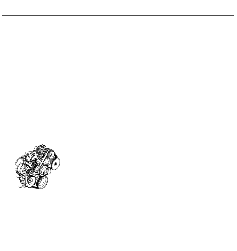
Serpentine drivebelt A single, long, wide
accessory drivebelt that's used on some
newer vehicles to drive all the accessories,
instead of a series of smaller, shorter belts.
Serpentine drivebelts are usually tensioned by
an automatic tensioner.
Serpentine drivebelt
Shim Thin spacer, commonly used to adjust
the clearance or relative positions between
two parts. For example, shims inserted into or
under bucket tappets control valve
clearances. Clearance is adjusted by
changing the thickness of the shim.
Slide hammer A special puller that screws
into or hooks onto a component such as a
shaft or bearing; a heavy sliding handle on the
shaft bottoms against the end of the shaft to
knock the component free.
Sprocket A tooth or projection on the
periphery of a wheel, shaped to engage with a
chain or drivebelt. Commonly used to refer to
the sprocket wheel itself.
Starter inhibitor switch On vehicles with an
automatic transmission, a switch that
prevents starting if the vehicle is not in Neutral
or Park.
Strut See MacPherson strut.
Tappet A cylindrical component which
transmits motion from the cam to the valve
stem, either directly or via a pushrod and
rocker arm. Also called a cam follower.
Thermostat A heat-controlled valve that
regulates the flow of coolant between the
cylinder block and the radiator, so maintaining
optimum engine operating temperature. A
thermostat is also used in some air cleaners in
which the temperature is regulated.
Thrust bearing The bearing in the clutch
assembly that is moved in to the release
levers by clutch pedal action to disengage the
clutch. Also referred to as a release bearing.
Timing belt A toothed belt which drives the
camshaft. Serious engine damage may result
if it breaks in service.
Timing chain A chain which drives the
camshaft.
Toe-in The amount the front wheels are
closer together at the front than at the rear. On
rear wheel drive vehicles, a slight amount of
toe-in is usually specified to keep the front
wheels running parallel on the road by
offsetting other forces that tend to spread the
wheels apart.
Toe-out The amount the front wheels are
closer together at the rear than at the front. On
front wheel drive vehicles, a slight amount of
toe-out is usually specified.
Tools For full information on choosing and
using tools, refer to the Haynes Automotive
Tools Manual.
Tracer A stripe of a second colour applied to
a wire insulator to distinguish that wire from
another one with the same colour insulator.
Tune-up A process of accurate and careful
adjustments and parts replacement to obtain
the best possible engine performance.
Turbocharger A centrifugal device, driven by
exhaust gases, that pressurises the intake air.
Normally used to increase the power output
from a given engine displacement, but can
also be used primarily to reduce exhaust
emissions (as on VW's "Umwelt" Diesel
engine).
U
Universal joint or U-joint A double-pivoted
connection for transmitting power from a
driving to a driven shaft through an angle. A
U-joint consists of two Y-shaped yokes and a
cross-shaped member called the spider.
Valve A device through which the flow of
liquid, gas, vacuum, or loose material in bulk
may be started, stopped, or regulated by a
movable part that opens, shuts, or partially
obstructs one or more ports or passageways.
A valve is also the movable part of such a
device.
Valve clearance The clearance between the
valve tip (the end of the valve stem) and the
rocker arm or tappet. The valve clearance is
measured when the valve is closed.
Vernier caliper A precision measuring
instrument that measures inside and outside
dimensions. Not quite as accurate as a
micrometer, but more convenient.
Viscosity The thickness of a liquid or its
resistance to flow.
Volt A unit for expressing electrical
"pressure" in a circuit. One volt that will
produce a current of one ampere through a
resistance of one ohm.
w
Welding Various processes used to join metal
items by heating the areas to be joined to a
molten state and fusing them together. For
more information refer to the Haynes
Automotive Welding Manual.
Wiring diagram A drawing portraying the
components and wires in a vehicle's electrical
system, using standardised symbols. For
more information refer to the Haynes
Automotive Electrical and Electronic Systems
Manual.
T
S
V

REF•16
Index
Note: References throughout this index relate to Chapter•page number
ACAV intake system - 4C•14, 4C•15
Accelerator cable - 4A•6, 4B•3, 4C•3
Accelerator pedal - 4A•6, 4B•3, 4C•3
Acknowledgements - 0•4
Aerial-12•18
Air bags - 0•5
Air cleaner - 1•20, 4A•2, 4A•3, 4B•2, 4B•3,
4 • 2
Air conditioning - 1 • 1 4 , 1 • 1 9 , 3•10,12•4
Air horn-12•13
Air temperature control valve - 4A•4, 4B•3
Airflow meter - 4C•10
Alarm -12•4,12•18
Alternator - 5•9
Anti-lock braking system (ABS) - 9•18,
9•19
Anti-roll bar - 10•8,10•9,10•15
Anti-theft system - 0•15, 12•18
Antifreeze-1•26
Asbestos - 0•5
Ashtray-12•8
Automatic transmission - 1 • 1 2 , 1 • 2 2 ,
2A•14, 2B•21, 2C•4, 2C•7, 7B•1 et seq
Automatic transmission fault finding -
REF•9
Auxiliary air valve - 4C•9, 4C•10
Auxiliary drivebelt -1 •17,1 •18,1 •19
Axle-10•17
B
Backfire - REF•6
Badges -11•13
Battery-0•5,1•11,5•3
Battery fault - REF• 11
Bearing shells - 2C•18, 2C•22
Big-end bearings - 2C•16, 2C•22
Bitron temperature sensor - 3•6
Bleeding brakes - 9•3
Bleeding power steering - 9•3
Blower motor - 3•9
Body corrosion - 0•10
Body electrical systems - 1 2 • 1 et seq
Bodywork and fittings - 1 1 •1 et seq
Bonnet-11•4,11•5
Booster battery (jump) starting - 0•14
Bosch Monopoint A2.2 system - 4B•3
Bosch Monopoint MA3.0 system - 4B•4
Bosch Monopoint system - 4B•7
Bosch Motronic M1.3 system - 4C•4, 4C•10
Bosch Motronic MP3.1 system - 4C•4,
4C•8
Bosch Motronic MP3.2 system - 4C•4,
4C•10
Bosch Motronic MP5.1 system - 4C•3,
4C•7
Brake fluid - 1 • 8 , 1 • 2 3
Braking system - 0•7, 0•8, 0•9, 9•1 et seq
Braking system fault finding - REF•9
Bulbs - 1 2 • 5 , 1 2 • 7
Bumpers - 11 •3,11 •4
Burning - 0•5
Cables - 3•8, 4A•6, 4B•3, 4C•3, 6•2, 7B•2,
7B•3,7B•4, 9•17, 11•5, 12•14
Calipers-9•5, 9•11,9•12
Camshaft - 2A•7, 2A•8, 2A•9, 2B•10, 2B•11,
2B•12
Camshaft position sensor - 4C•11
Capacities -1 •2
Carburettor - 4A•7, 4A•8, 4A•9, 4A•10
Carpets-11•17
Catalytic converter - 4B•12, 4D•2, 4D•3
Central locking-11•11
Central locking fault - REF•11
Centre console -11•17
Charcoal canister - 4D•2
Charging system - 5•8
Choke cable - 4A•6
Choke pull-down setting - 4A•10, 4A•11
Cigarette lighter - 1 2 • 8 , 12•12
Clock - 1 2 • 8 , 12•12
Clutch- 1•19, 6•1 et seq
Clutch fault finding - REF•8
CO emissions (mixture) - 0•10,1•16, 4A•10,
4A•11,4C•9
Coil - 5•5
A
C

Index
REF•17
Compression test - 2A•3, 2B•4
Connecting rods - 2 C • 1 1 , 2C•14, 2C•22,
2C•23
Contents - 0•2
Conversion factors - 0•16
Coolant - 1 • 8 , 1•23, 1•25
Coolant pump - 3•7
Coolant temperature sensor - 4B•8, 4B•10,
4C•7, 4C•9, 4C•10, 4C•11, 4C•13
Cooling system fault finding - REF•7
Cooling, heating and ventilation systems -
3•1 et seq
Corrosion - REF•8
Courtesy lights - 1 2 • 4 , 1 2 • 7
Crankcase - 2C•13
Crankcase emission control - 4D•1, 4D•2
Crankshaft - 2A•8, 2A•13, 2B•10, 2B•11,
2B•12, 2B•20, 2C•12, 2C•16, 2C•18,
2C•20, 4C•8, 4C•10, 4C•11, 4C•13
Crankshaft pulley - 2B•6
Crankshaft sensor - 4B•9, 4B•10
Crushing - 0•5
CV joint - 1 • 1 3
Cylinder block - 2C•13
Cylinder head - 2A•10, 2B•15, 2B•17, 2C•9,
2 C • 1 0 , 2 0 1 1
Cylinder head cover - 2A•4, 2B•5
Dents in bodywork - 1 1 •2
Dim-dip lighting system -12•19
Dimensions - 0•6
Dimmer switch - 1 2 • 4
Direction indicator - 1 2 • 6 , 1 2 • 9
Discs - 9 • 9 , 9•10
Distributor - 5•6
Door-open warning display -12•12
Doors - 0•8, 11 •5,11 •6,11 •7,11 •8, 11 •9,
11•10,11•11,1•15
Drivebelts - 1 • 1 7 , 1 • 1 8 , 1 • 1 9 , 5•9
Driveplate - 2B•20, 2B•21
Driveshafts - 0•9, 1•13, 7A•4, 7B•4, 8•1 et
seq
Driveshafts fault finding - REF•9
Drivetrain - 1 •20
Drums - 9•10
Earth fault-12•3
Electric cooling fan(s) - 3•5
Electric shock - 0•5
Electric windows - 11•12, 12•5
Electric windows fault - REF•11
Electrical system - 0•8,1•10
Electrical system fault finding - REF•11
Electronic control unit (ECU) - 4B•8, 4B•10,
4C•7, 4C•8, 4C•10, 4C•11, 4C•12, 11 •11
Emission checks - 0•10
Emission control systems - 1 • 1 7 , 4D•1 et
seq
Engine electrical systems - 5•1 et seq
Engine removal and general overhaul
procedures - 2C•1 et seq
Engine fault finding - 5•5, REF•6 , REF•9
Engine oil and filter-1 •8,1•11
Environmental considerations - REF•4
Evaporative emission control - 4 D • 1 , 4D•2
Exhaust emission control - 4 D • 1 , 4D•2
Exhaust manifold - 4A•11, 4B•11, 4C•15
Exhaust system - 0•9, 4A•12, 4B•11, 4C•16
Facia-11•18
Facia vents-3•10
Fan(s) - 3•5
Fault finding - REF•5 et seq
Fault finding - carburettor - 4A•9, 4A•10
Fault finding - electrical system - 5•2,12•2
Filling-11•2
Fire - 0•5
Float height setting - 4A•10, 4A•11
Fluid cooler - 7B•4
Fluid level checks-1•8
Flywheel - 2A•13, 2B•20, 2B•21
Foglight-12•6,12•9
Footwell trim panel -11•17
Fuel and exhaust systems - carburettor
engines - 0•10, 4A•1 et seq
Fuel and exhaust systems - multi-point
fuel injection models - 0•10, 4C•1 et
seq
Fuel and exhaust systems - single-point
fuel injection models - 0•10, 4B•1 et
seq
Fuel and exhaust systems fault finding -
REF•8
Fuel consumption high - REF•8
Fuel filter-1•15,1•26
Fuel gauge -12•12
Fuel gauge sender unit - 4A•4, 4B•5, 4C•5
Fuel injectors - 4B•7, 4B•9, 4C•7
Fuel leakage and/or fuel odour - REF•8
Fuel pressure regulator - 4B•7, 4B•9, 4C•7,
4C•8,4C•10,4C•11,4C•12
Fuel pump - 4A•4, 4B•5, 4C•4
Fuel rail and injectors - 4C•8, 4C•10, 4C•12
Fuel tank - 4A•5, 4B•5, 4C•5
Fuel/air mixture temperature sensor -
4B•10
Fume or gas intoxication - 0•5, REF•8
Fuses- 12•3
Gaiters-1•13, 8•3, 10•21
Gashes in bodywork - 1 1 •2
Gasketsw-2B•17, REF•4
Gear selection fault - REF•8, REF•9
Gearchange linkage - 7A•3
Glossary of technical terms - REF•12
Glovebox-11•17
H
Handbrake - 0•7, 9•17, 12•5
Handles-11•7
HC emissions - 0•10
Headlight - 12•5,12•9, 12•10
Headlining-11•17
Heat shield(s) - 4A•12, 4B•12, 4C•16
Heater - 3•3, 3•7, 3•8, 3•9, 3•10,12•9
Hinges-1•22
Horn-12•13
Horn fault-REF•11
Hoses - 3•2, 3•3
Hubs-10•5,10•10,10•11
Hydraulic pipes and hoses - 9•3
Hydraulic system - 9•2
Hydrofluoric acid - 0•5
I
Idle control auxiliary air valve - 4B•9
Idle control stepper motor - 4B•7, 4B•9
idle speed - 1 • 1 6 , 4A•10, 4A•11, 4C•7,
4C•9,4C•11,4C•12
Ignition fault-REF• 11
Ignition HT coil - 5•5
Ignition switch - 5•12, 10•20, 12•4
Ignition system - 1 • 1 6 , 5•4, 5•5
Ignition timing - 1 • 1 6 , 5•8
Injector resistor - 4B•8
Inlet manifold - 4A•11, 4B•10, 4C•13
Input shaft - 7A•5
Instruments - 1 •20
Instrument fault - REF•11
Instrument panel - 12•4,12•8, 12•10, 12•11
Instrument shroud - 1 2 • 4
Intake air temperature sensor - 4B•8, 4C•7,
4C•9, 4C•10, 4C•11, 4C•13
Intensive maintenance -1 •4
Introduction to the Citroen ZX - 0•4
Jacking-0•12
Joint mating faces - REF•4
Jump starting - 0•14
K
Kickdown cable - 7B•4
Knock sensor - 4C•11, 4C•13
Lambda sensor - 4D•2
Leaks-0•15, 1•12, REF•8
Lights-on warning system -12•13
Locknuts, locktabs and washers - REF•4
Locks - 1 •22, 10•20, 11 •5,11 •7,11 •8,
11•11, 12•4
Loudspeakers -12•17
Lower arm - 1 0 • 7 , 1 0 • 8
Lubricants and fluids -1 •2
Luggage compartment - 1 1 •15,11 •16,
12•5,12•8
D
E
F
G
J
L

REF•18
Index
M
Magneti Marelli system - 4B•4, 4B•9, 4C•4,
4C•12
Main bearings - 2C•16, 2C•19
Maintenance - Also see Routine
maintenance
Maintenance - bodywork and underframe -
11•1
Maintenance - upholstery and carpets -
11•2
Manifold absolute pressure (MAP) sensor -
4B•10, 4C•7, 4C•9, 4C•10, 4C•11,
4C•12
Manifolds - 4A•11, 4B•10, 4B•11, 4C•13,
4C•15
Manual steering gear -10•21
Manual transmission - 1 • 2 2 , 1•26, 2A•14,
2B•21, 2C•4, 2C•7, 7A•1 et seq
Manual transmission fault finding - REF•8
Map reading light - 1 2 • 8
Master cylinder - 9•14
Mirrors- 0•7, 11•12,11•13, 12•4
Misfire - REF•7
Mixture - 0•10, 1 •16, 4A•10, 4A•11, 4C•9
Modulator (braking system) - 9•19
MOT test checks - 0•7
Mountings - 2A•14, 2B•21
N
Number plate light -12•7,12•10
Oil and filter-1•11
Oil cooler - 2B•20
Oil level sensor - 5•12
Oil pressure warning light illuminated with
engine running - REF•7
Oil pressure warning light switch - 5•12
Oilpump-2A•13, 2B•19
Oil seals - 2A•8, 2A•13, 2B•12, 2B•20, 7A•4,
7B•4, REF•4
Oil temperature sensor - 5•12
Open-circuit- 12•2
Overcooling - REF•7
Overheating - REF•7
Pads-1•13, 1•20,9•4,9•6
Pedals - 4A•6, 4B•3, 4C•3, 6•2, 9•15
Piston rings - 2C• 17
Pistons - 2C•11, 2C•14, 2C•22, 2C•23
Pitching and/or rolling around corners -
REF•10
Plastic components - 1 1 •3
Poisonous or irritant substances - 0•5
Power steering fluid -1 •9
Power-assisted steering gear - 1 0 • 2 1 ,
10•22
Pressure-regulating valves (braking
system) - 9•18
Printed circuit -12•12
Project vehicles - 0•4
Purge valve - 4D•2
Quarter window -11•13
Radiator - 1 • 2 5 , 3•2, 3•3, 3•4
Radio aerial-12•18
Radio/cassette player -12•17
Radio/cassette unit anti-theft system -
0•15
Rear axle-10•17
Rear light cluster -12•7,12•10
Receiver unit -11•12
Refrigerant - 1 • 1 4
Regulator (alternator) - 5•9
Regulator (window) - 11 •8, 11 •9,11 •10,
11•12
Relay unit - 4B•8, 4B•10, 4C•8, 4C•10,
4C•11,4C•13
Relays - 9 • 2 1 , 12•3
Reluctor rings (braking system) - 9•21
Repair procedures - REF•4
Respraying - 1 1 •2
Reversing light - 7A•6, 7B•5
Ride height-10•17
Road test -1 •20
Rocker arm - 2A•8, 2A•9
Routine maintenance and servicing -1 •1 et
seq,11•1, 11•2
Rubber gaiters - 1 • 1 3 , 8•3, 10•21
Rust holes in bodywork - 1 1 •2
Safety first! - 0•5
Scalding - 0•5
Scratches in bodywork - 11 •2
Screw threads and fastenings - REF•4
Seat belts - 0•8, 11•14
Seats - 0•8, 11•14
Selector - 7B•2, 7B•3
Selector lever - 7B•3, 7B•5, 12•8
Selector lever fault - REF•9
Selector shaft - 7A•5, 7B•4
Servo unit - 9•15, 9•16
Shock absorber - 0•8, 0•9, 1 •13, 10•11
Shoes - 1•19, 9•7
Short-circuit - 12•3
Sidelight - 12•6
Solenoid valve - 4C•15
Solex 32 PBISA carburettor - 4A•7, 4A•9
Solex 32•34 Z2 carburettor - 4A•7, 4A•10
Spare parts - 0•11
Sparkplugs - 1•14
Speed sensor - 4B•9, 4C•11, 4C•13
Speedometer - 7A•6, 7B•4, 12•11, 12•14
Springs - 0•9
Starter inhibitor - 7B•5
Starter motor - 5•10, 5•11
Starter motor fault - REF•6
Starting system - 5•10
Steering - 0•8, 0•9, 1•12, 1•20, 10•20,
10•21
Steering angles -10•23
Steering fault - REF•10
Steering wheel and column - 0•7, 10•18,
10•20, 12•4
Stop-light switch - 9 • 1 8
Struts - 1•13,10•5,10•6, 11 •10, 11 •11
Subframe - 10•9
Sump - 2A•12, 2B•18
Sunroof - 11•13, 12•5
Suspension and steering - 0•8, 0•9, 1•12,
1•13, 1•20, 10•1 et seq
Suspension and steering fault finding -
REF•10
Switches - 3•5, 3•6, 4A•3, 4B•3, 4C•10,
5•12, 7A•6, 7B•5, 9•18, 11•12, 11•13,
12•4,12•9
Swivel h u b - 1 0 • 4
Tachometer-12•11
Tailgate-11•10,11•11, 11•13, 12•15,
12•16, 12•17, REF•11
Tailpipe - 4A•12, 4B•12, 4C•16
Temperature gauge - 3•6,12•12
Temperature sensor - 3•6, 4B•8, 4B•10,
4C•7, 4C•9, 4C•10, 4C•11, 4C•13
Temperature warning light - 3•6
Thermostat - 3•4
Throttle body - 4B•5
Throttle housing - 4C•5, 4C•8, 4C•12,
4C•13
Throttle potentiometer - 4B•8, 4B•10, 4C•7,
4C•8,4C•11,4C•12
Throttle switch - 4C•10
Throttle valve fast idle setting - 4A•10,
4A•11
Timing - 1 • 1 6 , 5•8
Timing belt -1 •26, 2A•5, 2A•6, 2A•7, 2B•7,
2B•10
Toe setting-10•24
Tools - REF•1, REF•3, REF•4
Torsion bar -10•12,10•13
Towing - 0 • 1 2
Track r o d - 1 0 • 2 2 , 10•23
Trailing arm - 1 0 • 1 4
Transmission - 1 • 1 2 , 1•22, 1•26, 2A•14,
2B•21, 2C•4, 2C•7, 7A•1 et seq, 7B•1 et
seq
Transmitter batteries -11•12
Trim panel-11•6, 11•15, 11•17
Trim strips -11•13
Til series engine in-car repair procedures -
2A•1 etseq
Tyre wear- REF•10
Tyres-0•10, 1•9
U
Under-panels -11•13
Unleaded petrol - 4A•7, 4B•3, 4C•3
Vacuum diaphragm unit - 4C•15
Vacuum pump (braking system) - 9•22
Vacuum servo unit - 9•15, 9•16
O
Q
R
P
S
T
V

Index
Vacuum switch - 4A•3, 4B•3
Valve clearances - 1•14, 2B•14
Valve timing holes - 2A•4, 2B•4
Valves - 2C•10,2C•11
Vehicle identification - 0•8, 0•11
Vehicle pulls to one side - REF•10
Vehicle ride height - 10•17
Ventilation - 3•7, 3•8
Vents - 3•10
w
Warning light switch - 12•5
Wash/wipe system - 12•16
Wash/wipe fault - REF•11
Washer fluid-1•9
Washer jet -12•17
Washer pump(s) -12•16
Water pump - 3•7
Weights - 0•6
Wheel alignment -10•23
Wheel arch liners -11•13
Wheel bearings - 0•9
Wheel changing - 0•13
Wheel cylinder-9•13
Wheel sensor - 9•20
Wheel wobble and vibration - REF•10
Wheels - 0•10
Wheels locking - REF•9
Window glass - 1 1 •8,11 •9,11 •10
Window regulator - 1 1 •9,11 •10
Window switches-11•12
Windows -11•8,11•12
Windscreen - 0•7, 11•13,11•17,12•14,
12•16, 12•17, REF•11
Wiper arm -12•14
Wiper blade-1•11
Wiper motor and linkage - 12•14,12•15
Wiring diagrams -12•19 et seq
Working facilities - REF•3
XU series engine in-car engine repair
procedures - 2B•1 et seq
REF•19
X
Wyszukiwarka
Podobne podstrony:
KSRG ref
ref 2004 04 26 object pascal
zx 01
emocje niespojne-ref, Onedrive całość, Rok I, II sem, Psychologia emocji i motywacji, Streszczenia
5366 Ref 22 id 41421 Nieznany (2)
BI Ref 4
zx 00
zx 04d
zx 08
Rodzina ref
ref Komisja Edukacji Narodowej
emocje spojne-ref, Onedrive całość, Rok I, II sem, Psychologia emocji i motywacji, Streszczenia
ref soc 251, Dokumenty(2)
Monia ref
wrażenia ref
Ref Rola i budowa skory
Ref six sigma
więcej podobnych podstron