
1•1
Chapter 1 Routine maintenance and servicing
Contents
Air conditioning system refrigerant check 14
Air filter renewal 26
Automatic transmission fluid level check 10
Automatic transmission fluid renewal 29
Auxiliary drivebelt checking and renewal 21
Battery check 6
Brake fluid renewal 30
Clutch adjustment check and control mechanism lubrication 22
Coolant renewal 31
Driveshaft gaiter check 12
Electrical system check 5
Emission control systems check 20
Engine oil and filter renewal 8
Fluid level checks .: 3
Front brake pad condition check 13
Fuel filter renewal - carburettor models 17
Fuel filter renewal - fuel injection models 32
Hinge and lock lubrication 27
Degrees of difficulty
Hose and fluid leak check 9
Idle speed and mixture check and adjustment 19
Ignition system check 18
intensive maintenance 2
Introduction 1
Manual transmission oil level check 28
Manual transmission oil renewal 34
Rear brake pad condition check - models with rear disc brakes . . . 24
Rear brake shoe condition check - models with rear drum brakes . 23
Road test 25
Spark plug renewal 16
Specifications See end of Chapter
Steering and suspension check 11
Timing belt renewal 33
Tyre checks 4
Valve clearance check and adjustment -1124 cc and 1360 cc
models 15
Wiper blade check 7
Easy, suitable for
novice with little
experience
Fairly easy, suitable
for beginner with
some experience
Fairty difficult, suitable
for competent DIY
mechanic
Difficult, suitable for
experienced DIY
mechanic
Very difficult,
suitable for expert DIY
or professional
Lubricants, Fluids & Capacities
Lubricants and fluids
Component or system
1 Engine
2 Cooling system
3 Manual transmission
4 Automatic transmission
5 Braking system
6 Power steering
Capacities
Engine oil
Excluding filter:
1124 cc and 1360 cc models 3.2 litres
1580 cc and 1905 cc models 4.5 litres
1761 cc models 4.4 litres
1998 cc models 4.7 litres
Including filter:
1124 cc and 1360 cc models 3.5 litres
1580 cc and 1905 cc models 5.0 litres
1761 cc models 4.9 litres
1998 cc models 5.4 litres
Difference between "MIN" and "MAX" dipstick marks (approximate):
Models without air conditioning 1.5 litres
Models with air conditioning 1.3 litres
Lubricant type/specification
Multigrade engine oil, viscosity SAE 10W/40or 15W/50, to API SG/CD
Ethylene glycol-based antifreeze
Total transmission BV75/80W
Dexron type IIATF
Total Universal Brake and Clutch Fluid
Dexron type II ATF
Cooling system
1124 cc and 1360 cc models:
Models without air conditioning 6.5 litres
Models with air conditioning 7.5 litres
1580 cc and 1905 cc models:
Models with manual transmission 7.5 litres
Models with automatic transmission 8.0 litres
1761 cc models 8.0 litres
1998 cc models 8.5 litres
Transmission
Manual 2.0 litres
Automatic:
From dry 6.2 litres
Drain and refill 2.4 litres
Power-assisted steering 1.7 litres
Fuel tank 56 litres
1•2

Maintenance schedule
Maintenance schedule
1 The maintenance intervals in this manual are provided on the
assumption that you, not the dealer, will be carrying out the work.
These are the minimum maintenance intervals recommended by the
manufacturer for vehicles driven daily. If you wish to keep your vehicle
in peak condition at all times, you may wish to perform some of these
procedures more often. We encourage frequent maintenance, because
it enhances the efficiency, performance and resale value of your
vehicle. If the vehicle is driven in dusty areas, used to tow a trailer, or is
driven frequently at slow speeds (idling in traffic) or on short journeys,
more frequent maintenance intervals are recommended.
2 Vehicles which cover a low mileage (less than 12 000 miles/20 000 km
per year) should be serviced following the time interval instead of the
mileage interval. This is necessary because many lubricants and fluids, as
well as some components, deteriorate with time as much as with use.
3 When the vehicle is new, it should be serviced by a factory-authorised
dealer service department, in order to preserve the factory warranty.
1•3
Every 250 miles (400 km) or weekly
• Check the engine oil level (Section 3)
• Check the engine coolant level (Section 3)
• Check the brake fluid level (Section 3)
• Check the power steering fluid level (Section 3)
• Check the screen washer fluid level (Section 3)
• Check the tyres for wear or damage (Section 4)
• Check and adjust the tyre pressures (Section 4)
• Check the condition of the battery (Section 6)
• Check the operation of the horn, all lights, and the wipers
and washers (Sections 5 and 7)
Every 6000 miles (10 000 km) or
6 months - whichever comes first
• Renew the engine oil and filter* (Section 8)
• Check all components and hoses for fluid leaks (Section 9)
• Check the automatic transmission fluid level (Section 10)
• C h e c k t h e s t e e r i n g a n d s u s p e n s i o n c o m p o n e n t s for
condition and security (Section 11)
• Check the condition of the driveshaft gaiters (Section 12)
• Check the condition of the front brake pads, and renew if
necessary (Section 13)
The manufacturer specifies that the oil filter should be renewed at the
first 6000 mile service, and then at 12 000 miles intervals, with only the
oil being drained and renewed every 6000 miles. Owners may prefer to
carry out filter renewal at the 6000-mile interval, as a precautionary task.
Every 12 000 miles (20 000 km) or
12 months - whichever comes first
In addition to all the items listed above, carry out the following:
• C h e c k t h e c o n d i t i o n of t h e air c o n d i t i o n i n g s y s t e m
refrigerant - where applicable (see Section 14)
• C h e c k a n d , if necessary, adjust t h e valve c l e a r a n c e s -
1124 cc and 1360 cc models (Section 15)*
• Renew the spark plugs (Section 16)
• Renew the fuel filter - carburettor models (Section 17)
• Check the ignition system and ignition timing (Section 18)
• Check the idle speed and mixture adjustment (Section 19)
• Check the condition of the emission control system hoses
and c o m p o n e n t s (Section 20)
• C h e c k the condition of the auxiliary drivebelt, and renew if
necessary (Section 21)
• Check the clutch mechanism adjustment (Section 22)
• Lubricate the clutch control mechanism (Section 22)
Every 40 000 miles (60 000 km) or
2 years - whichever comes first
• Renew the coolant (Section 31)
• Renew the fuel filter - fuel injection models (Section 32)
Every 24 000 miles (40 000 km) or
2 years - whichever comes first
In addition to all the items listed above, carry out the following:
• C h e c k t h e m a n u a l transmission oil level, a n d t o p - u p if
necessary (Section 28)
• Renew the automatic transmission fluid (Section 29)
• Renew the brake fluid (Section 30)
Every 18 000 miles (30 000 km) or
18 months - whichever comes first
In addition to all the items listed above, carry out the following:
• Renew the air filter (Section 26)
• Lubricate all hinges and locks (Section 27)
Every 72 000 miles (116 000 km)
• Renew the manual transmission oil (Section 34)
Every 48 000 miles (80 000 km)
• Renew the timing belt (Section 33)
Note: On all 1998 cc models, Citroen have extended the timing belt
renewal interval to 72 000 miles. However, it is also stated that,
should the vehicle be subjected to intensive use, ie. mainly short
journeys or a lot of stop-start driving, the belt should be renewed
every 36 000 miles. The actual belt renewal interval is therefore very
much up to the individual owner. That being said, it is highly
recommended to err on the side of safety, and renew the belt at the
earlier interval. It is certainly not advisable to exceed the 48 000 mile
interval recommended for all other models, bearing in mind the
drastic consequences resulting from belt failure.
• Check the condition of the rear brake shoes, and renew if
necessary - rear drum brake models (Section 23)
• C h e c k t h e c o n d i t i o n o f the rear d i s c brake p a d s , a n d
renew if necessary - rear disc brake models (Section 24)
• Carry out a road test (Section 25)
*The manufacturer suggests this operation at the first 12 000 mile
service only. After that, checking and adjusting of the valve
clearances is not part of the recommended maintenance schedule.
Maintenance and Servicing
1 This Chapter is designed to help the home
mechanic maintain his/her vehicle for safety,
economy, long life and peak performance.
2 The Chapter contains a master
maintenance schedule, followed by Sections
dealing specifically with each task on the
schedule. Visual checks, adjustments,
component renewal, and other helpful items
are included. Refer to the accompanying
illustrations of the engine compartment and of
the underside of the vehicle for the locations
of the various components.
3 Servicing your vehicle in accordance with
the mileage/time maintenance schedule and
the following Sections will provide a planned
maintenance programme, which should result
in a long and reliable service life. This is a
comprehensive plan, so maintaining some
items but not others at the specified service
intervals, will not produce the same results.
4 As you service your vehicle, you will
discover that many of the procedures can -
and should - be grouped together, either
because of the particular procedure being
performed, or because of the close proximity
of two otherwise-unrelated components to
one another. For example, if the vehicle is
raised for any reason, the exhaust can be
inspected at the same time as the suspension
and steering components.
5 The first step in this maintenance
programme is to prepare yourself before the
actual work begins. Read through all the
Sections relevant to the work to be carried
out, then make a list of, and gather together,
all the parts and tools required. If a problem is
encountered, seek advice from a parts
specialist, or a dealer service department.
1 If, from the time the vehicle is new, the
routine maintenance schedule is followed
closely, and frequent checks are made of fluid
levels and high-wear items, as suggested
throughout this manual, the engine will be
kept in relatively good running condition, and
the need for additional work will be minimised.
2 It is possible that there will be times when
the engine is running poorly, due to the lack of
regular maintenance. This is even more likely
if a used vehicle, which has not received
regular and frequent maintenance checks, is
purchased. In such cases, additional work
may need to be carried out, outside of the
regular maintenance intervals.
3 If engine wear is suspected, a compression
test (Chapter 2, Part A) will provide valuable
information regarding the overall performance
of the main internal components. Such a test
can be used as a basis to decide on the
extent of the work to be carried out. If, for
example, a compression test indicates serious
internal engine wear, the conventional
maintenance described in this Chapter will not
greatly improve the performance of the
engine, and may prove a waste of time and
money, unless extensive overhaul work is
carried out first.
4 The following series of operations are those
most often required to improve the
performance of a generally poor-running
engine:
Clean, inspect and test the battery (Sec-
tion 6).
Check the levels of all the engine-related
fluids (Section 3).
Check the condition and tension of the
auxiliary drivebelt (Section 21).
Check the fuel filter, and renew if necessary
(Sections 17 or 32).
Check the condition of the air filter, and
renew if necessary (Section 26).
Check the condition of all hoses, and check
for fluid leaks (Section 9).
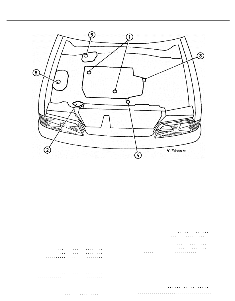
Underbonnet view of a 1360 cc fuel
injection (KDY engine) model
1 Engine oil filler cap
2 Engine oil dipstick
3 Battery
4 Master cylinder brake fluid reservoir
5 Engine compartment junction box
6 Engine oil filter
7 Radiator filler cap
8 Alternator
9 Windscreen/tailgate washer fluid reservoir
filler cap
10 Braking system vacuum servo unit
11 Ignition HT coil
12 Plastic box containing the fuel injection
ECU, relay unit and injector resistor
13 Suspension strut upper mounting
14 Air cleaner air temperature control valve
15 Throttle body assembly
16 Evaporative emission control purge valves
17 Ignition timing retard system solenoid
valve
18 Air cleaner housing
1•4
1 Introduction
2 Intensive maintenance
Maintenance and Servicing
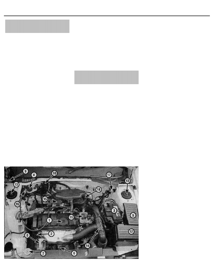
Underbonnet view of a 1580 cc
(BDY engine) model
1 Engine oil filler cap
2 Engine oil dipstick
3 Battery
4 Master cylinder brake fluid reservoir
5 Engine compartment junction box
6 Engine oil filter
7 Radiator filler cap
8 Alternator
9 Windscreen/tailgate washer fluid reservoir
filler cap
10 Braking system vacuum servo unit
11 Ignition HT coil
12 Plastic box containing the fuel injection
ECU and relay unit
13 Suspension strut upper mounting
14 Air cleaner air temperature control valve
15 Throttle body assembly
16 Fuel injection system MAP sensor
17 Thermostat housing
18 Air cleaner housing
Underbonnet view of a 1761 cc
(LFZ engine) model
1 Engine oil filler cap
2 Engine oil dipstick
3 Battery
4 Master cylinder brake fluid reservoir
5 Engine compartment junction box
6 Engine oil filter
7 Radiator filler cap
8 Alternator
9 Windscreen/tailgate washer fluid reservoir
filler cap
10 Braking system vacuum servo unit
11 Ignition HT coil
12 Plastic box containing the fuel injection
ECU
13 Suspension strut upper mounting
14 Fuel injection system relay unit
15 Throttle housing assembly
16 Fuel injection system MAP sensor
17 Idle speed auxiliary air valve
18 Air cleaner element cover
1•5
Maintenance and Servicing
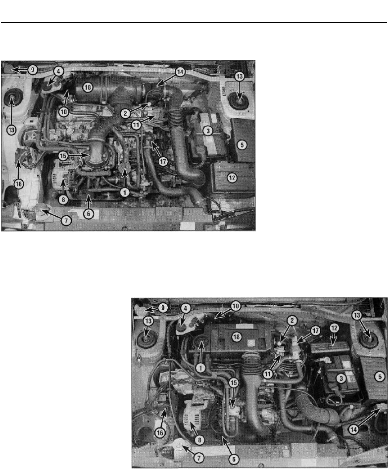
Underbonnet view of a 1905 cc
(D6E engine) model
1 Engine oil filler cap
2 Engine oil dipstick
3 Battery
4 Master cylinder brake fluid reservoir
5 Engine compartment junction box
6 Engine oil filter
7 Radiator filler cap
8 Alternator
9 Windscreen/tailgate washer fluid reservoir
filler cap
10 Braking system vacuum servo unit
11 Ignition HT coil
12 Fuel injection ECU
13 Suspension strut upper mounting
14 Fuel injection system relay unit
15 Throttle housing assembly
16 Fuel injection system intake air
temperature sensor
17 Air cleaner housing
18 Power steering fluid reservoir
19 Fuel pressure regulator
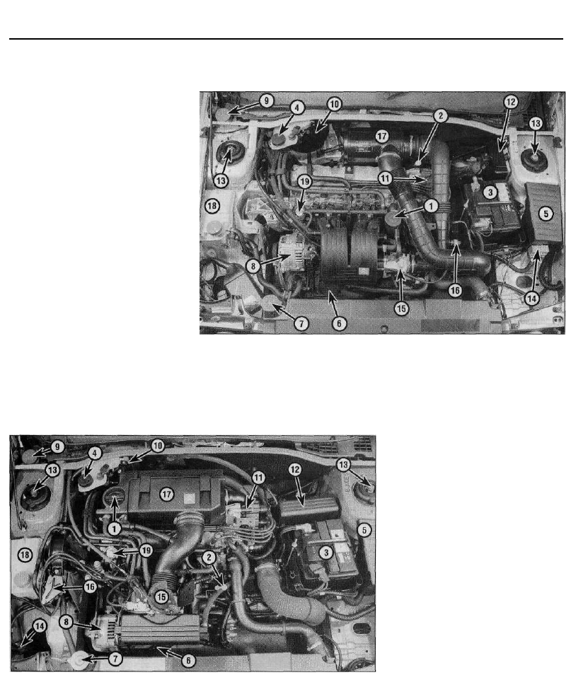
Underbonnet view of a 1998 cc 8-valve
(RFX engine) model
1 Engine oil filler cap
2 Engine oil dipstick
3 Battery
4 Master cylinder brake fluid reservoir
5 Engine compartment junction box
6 Engine oil filter
7 Radiator filler cap
8 Alternator
9 Windscreen/tailgate washer fluid reservoir
filler cap
10 Braking system vacuum servo unit
11 Ignition HT coil
12 Plastic box containing the fuel injection
ECU
13 Suspension strut upper mounting
14 Evaporative emission control system
purge valve
15 Throttle housing assembly
16 Fuel injection system MAP sensor
17 Air cleaner housing cover
18 Power steering fluid reservoir
19 Fuel pressure regulator
1•6
Maintenance and Servicing
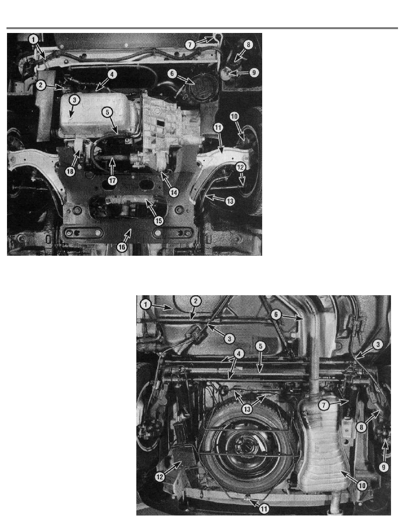
Front underbody view - 1998 cc 16-valve
model shown (other models similar)
1 Wiring harness
2 Power steering pump
3 Sump drain plug
4 Oil filter
5 Power steering fluid hose
6 Air filter housing
7 Towing eye
8 Horn
9 Horn compressor
10 Brake caliper
11 Lower suspension arm
12 Track rod balljoint
13 Anti-roll bar
14 Transmission oil drain plug
15 Steering gear assembly
16 Front suspension subframe
17 Driveshaft
18 Engine/transmission rear mounting
Rear underbody view - rear disc brake
model shown (drum brake models similar)
1 Fuel tank
2 Fuel tank support bracket
3 Handbrake cables
4 Rear suspension torsion bars
5 Rear suspension tubular crossmember
6 Exhaust heat shield
7 Rear shock absorber
8 Rear suspension trailing arm
9 Brake caliper
10 Rear exhaust box
11 Spare wheel cradle retaining catch
12 Jack case
13 Rear brake pressure-regulating valves
1•7
Weekly Checks
Weekly checks
3 Fluid level checks
Engine oil
1 The engine oil level is checked with a
dipstick. This extends through the dipstick
tube, into the sump at the bottom of the
engine. On 1124 cc, 1360 cc and 1998 cc
8-valve models, the dipstick is located at the
front of the engine. On all other models, the
dipstick is located at the rear of the engine.
The dipstick top is brightly-coloured (usually
orange) for easy identification.
2 The oil level should be checked with the
vehicle standing on level ground. Check the
level before the engine is started, or wait at
least 5 minutes after the engine has been
switched off.
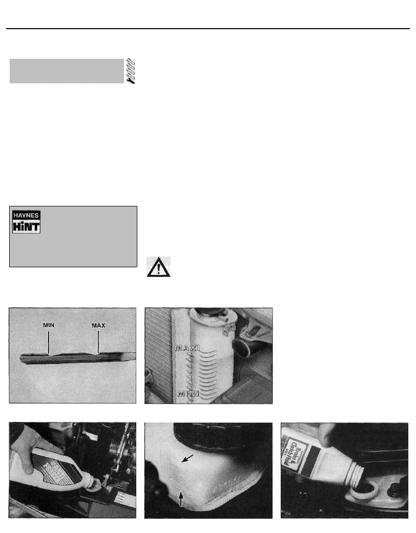
3 Withdraw the dipstick from the tube, and
wipe all the oil from the end with a clean rag or
paper towel. Insert the clean dipstick back
into the tube as far as it will go, then withdraw
3.3 Engine oil level dipstick markings
it once more. Note the oil level on the end of
the dipstick. Add oil as necessary until the
level is between the upper ("MAX") mark and
lower ("MIN") mark on the dipstick (see
illustration). Approximately 1.5 litres of oil will
be required to raise the level from the lower
mark to the upper mark, on models without air
conditioning. The amount is 1.3 litres on
models with air conditioning.
4 Always maintain the level between the two
dipstick marks. If the level is allowed to fall
below the lower mark, oil starvation may
result, which could lead to severe engine
damage. If the engine is overfilled by adding
too much oil, this may result in oil leaks or oil
seal failures.
5 Oil is added to the engine either via the filler
cap on the cylinder head cover (1124 cc,
1360 cc, 1761 cc and 1998 cc 8-valve models)
or via the filler/breather cap (1580 cc, 1905 cc
and 1998 cc 16-valve models). Unscrew the
cap and top-up the level - an oil can spout or
funnel may help to reduce spillage. Always use
the correct grade and type of oil, as shown in
"Lubricants, fluids and capacities".
Coolant
Warning: DO NOT attempt to
remove the expansion tank
pressure cap when the engine is
hot, as there is a very great risk
of scalding.
6 All vehicles covered by this manual are
3.7 Coolant expansion tank level markings
equipped with a pressurised cooling system.
An expansion tank is incorporated in the right-
hand side of the radiator. As the engine
temperature increases, the coolant expands,
and the level in the expansion tank rises. As
the engine cools, the coolant is automatically
drawn back into the system, to maintain the
correct level.
7 The coolant level in the expansion tank
should be checked regularly. The level in the
tank varies with the temperature of the engine.
When the engine is cold, the coolant level
should be between the "MIN" and "MAX"
marks on the side of the tank. When the
engine is hot, the level may rise slightly above
the "MAX" mark (see illustration).
8 If topping-up is necessary, wait until the
engine is cold, then turn the pressure cap on
the expansion tank anti-clockwise until it
reaches the first stop. Wait until any pressure
remaining in the system is released, then push
the cap down, turn it anti-clockwise to the
second stop, and lift it off.
9 Add a mixture of water and antifreeze (see
Section 31) through the expansion tank filler
neck, until the coolant is approximately
halfway between the two level marks (see
illustration). Refit the cap, turning it
clockwise as far as it will go to secure.
10 With a "sealed" cooling system such as
this, the addition of coolant should only be
necessary at very infrequent intervals. If
frequent topping-up is required, it is likely there
is a leak in the system. Check the radiator, and
all hoses and joint faces, for any sign of staining
or actual wetness, and rectify as necessary. If
no leaks can be found, it is advisable to have
the pressure cap (and the entire system)
pressure-tested by a dealer or suitably-
equipped garage. This will often show up small
leaks which were not previously visible.
Brake fluid
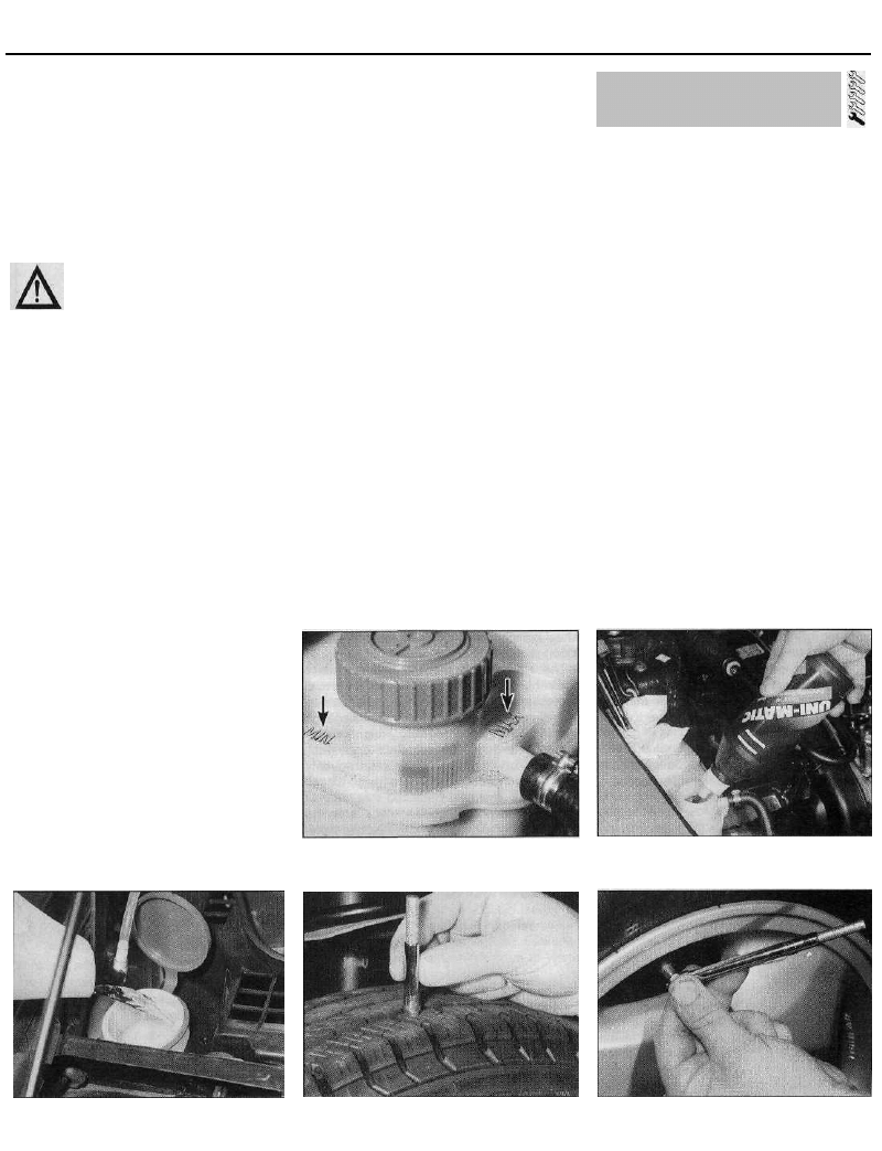
11 The brake master cylinder and fluid
reservoir assembly is mounted on the front of
the vacuum servo unit in the engine
compartment. The maximum and minimum
marks are indicated on the side of the
reservoir (see illustration). The fluid level
3.9 Topping-up the coolant level
3.11 Brake fluid reservoir level markings
3.12 Topping-up the brake fluid level
1•8
If the oil is checked
immediately after switching
off the engine, some of the oil
will remain in the upper
engine components and oil galleries,
resulting in an inaccurate reading on
the dipstick.
Weekly Checks
should be maintained between these marks at
ail times.
12 If topping-up is necessary, first wipe the
area around the "filier cap with a clean rag
before removing the cap. When adding fluid,
pour it carefully into the reservoir, to avoid
spilling it on surrounding painted surfaces
(see illustration). Be sure to use only the
specified brake hydraulic fluid, since mixing
different types of fluid can cause damage to
the system. Refer to "Lubricants fluids and
capacities" at the beginning of this Chapter.
Warning: Brake hydraulic fluid
can harm your eyes, and will
damage painted surfaces, so
use extreme caution when
handling and pouring it. It is also highly-
inflammable. Do not use fluid that has
been standing open for some time, as it
absorbs moisture from the air. Excess
moisture in the fluid can cause a
dangerous loss of braking effectiveness.
13 When adding fluid, it is a good idea to
inspect the reservoir for contamination. The
system should be drained and refilled if
deposits, dirt particles or contamination are
seen in the fluid.
14 After filling the reservoir to the correct
level, make sure that the cap is refitted
securely, to avoid leaks and the entry of
foreign matter.
15 The fluid level in the master cylinder
reservoir will drop slowly as the brake pads
and shoes wear down during normal
operation. Provided that the level does not
drop below the minimum mark, there is no
need to top up to compensate for this fall. The
level will rise again when new brake pads or
linings are fitted. If the reservoir requires
repeated replenishing to maintain the proper
level, this is an indication of a hydraulic leak
somewhere in the system, which should be
investigated immediately.
Power steering fluid
16 The power steering fluid reservoir is
located on the right-hand side of the engine
compartment.
17 For the check, the car should be parked
on level ground, with the front wheels pointing
straight-ahead. The engine should be
switched off. For the check to be accurate,
the steering must not be turned once the
engine has been stopped.
18 The fluid level is visible in the reservoir,
and should be between the "MAX" and "MIN"
level lines cast on the side of the reservoir
(see illustration).
19 If topping-up is necessary, wipe the area
around the reservoir cap clean, then unscrew
the cap. Top-up to the "MAX" mark using the
specified type of fluid (see illustration). Take
great care not to allow any dirt or foreign matter
to enter the hydraulic system, and do not
overfill the reservoir. When the level is correct,
refit the cap. Note that the need for frequent
topping-up of the system indicates a leak,
which should be investigated immediately.
Washer fluid
20 The windscreen/tailgate washer fluid
reservoir filler is located at the rear right-hand
corner of the engine compartment, behind the
suspension strut (see illustration).
21 On models fitted with a headlight washer
system, an additional reservoir is located
under the front right-hand wing. To top-up the
reservoir, turn and extend the filler neck which
protrudes into engine compartment.
22 When topping-up the reservoir(s), a
screenwash additive should be added, in its
manufacturer's recommended quantities. The
additive used in winter must give protection
against freezing. Do not use engine antifreeze
in the screen washer reservoir; it will damage
the wiper blades and the paintwork.
4 Tyre checks
1 The original tyres on this car are equipped
with tread wear safety bands, which will
appear when the tread depth reaches
approximately 1.6 mm. Tread wear can be
monitored with a simple, inexpensive device
known as a tread depth indicator gauge (see
illustration).
2 Wheels and tyres should give no real
problems in use, provided that a close eye is
kept on them with regard to excessive wear or
damage. To this end, the following points
should be noted.
3 Ensure that the tyre pressures are checked
regularly and maintained correctly. Checking
should be carried out with the tyres cold, and
not immediately after the vehicle has been in
use (see illustration). If the pressures are
checked with the tyres hot, an apparently-
high reading will be obtained, owing to heat
expansion. Under no circumstances should an
attempt be made to reduce the pressures to
the quoted cold reading in this instance, or
effective under-inflation will result.
4 Note any abnormal tread wear (see
illustration). Tread pattern irregularities such
as feathering, flat spots, and more wear on
one side than the other, are indications of
front wheel alignment and/or balance
problems. If any of these conditions are
noted, they should be rectified as soon as
possible.
3.18 Power steering fluid reservoir
markings
3.19 Topping-up the power steering fluid
level
3.20 Topping-up the washer fluid level
4.1 Checking a tyre tread depth with a
depth gauge
4.3 Checking a tyre pressure with a tyre
pressure gauge
1•9
Weekly Checks
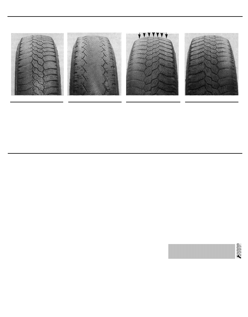
Tyre Tread Wear Patterns
Shoulder Wear
Underinflation
(wear on both sides)
Check and adjust pressures
Incorrect wheel camber
(wear on one side)
Repair or renew suspension
parts
Hard cornering
Reduce speed!
Centre Wear
Toe Wear
Uneven Wear
Overinflation
Check and adjust pressures
If you sometimes have to inflate
your car's tyres to the higher
pressures specified for maximum
load or sustained high speed,
don't forget to reduce the pres-
sures to normal afterwards.
Incorrect toe setting
Adjust front wheel alignment
Note: The feathered edge of
the tread which characterises
toe wear is best checked by
feel.
Incorrect camber or castor
Repair or renew suspension
parts
Malfunctioning suspension
Repair or renew suspension
parts
Unbalanced wheel
Balance tyres
Qut-of-round brake disc/drum
Machine or renew
5 Under-inflation will cause overheating of the
tyre, owing to excessive flexing of the casing,
and the tread will not sit correctly on the road
surface. This will cause a consequent loss of
adhesion and excessive wear, not to mention
the danger of sudden tyre failure due to heat
build-up.
6 Over-inflation will cause rapid wear of the
centre part of the tyre tread, coupled with
reduced adhesion, harsher ride, and the
danger of shock damage occurring in the tyre
casing.
7 Regularly check the tyres for damage in the
form of cuts or bulges, especially in the
sidewalls. Remove any nails or stones
embedded in the tread, before they penetrate
the tyre to cause deflation. If a nail is
removed, revealing that the tyre has been
punctured, refit the nail so that its point of
penetration is clearly marked. Change the
wheel immediately, and have the tyre repaired
by a tyre dealer. Do not drive on a tyre in such
a condition. If in any doubt as to the possible
consequences of any damage found, consult
your local tyre dealer for advice.
8 Periodically remove the wheels, and clean
any dirt or mud from the inside and outside
surfaces. Examine the wheel rims for signs of
rusting, corrosion or other damage. Light alloy
wheels are easily damaged by "kerbing"
whilst parking, and similarly, steel wheels may
become dented or buckled. Renewal of the
wheel is very often the only course of remedial
action possible.
9 The balance of each wheel and tyre
assembly should be maintained, to avoid
excessive wear, not only to the tyres, but also
to the steering and suspension components.
Wheel imbalance is normally signified by
vibration through the vehicle's bodyshell,
although in many cases it is particularly
noticeable through the steering wheel.
Conversely, it should be noted that wear or
damage in suspension or steering
components may cause excessive tyre wear.
Out-of-round or out-of-true tyres, damaged
wheels, and worn wheel bearings also fall into
this category. Balancing alone will not usually
cure vibration caused by such wear.
10 Wheel balancing may be carried out with
the wheel either on or off the vehicle. If
balanced on the vehicle, ensure that the
wheel-to-hub relationship is marked in some
way prior to subsequent wheel removal, so
that it may be refitted in its original position.
11 General tyre wear is influenced to a large
degree by driving style - harsh braking and
acceleration, or fast cornering, will all produce
more rapid tyre wear. Interchanging of tyres
may result in more even wear. However, it is
worth bearing in mind that if this is completely
effective, the added expense is incurred of
renewing four tyres at once, which may prove
financially restrictive for many owners.
12 Front tyres may wear unevenly as a result
of wheel misalignment. The front wheels
should always be correctly aligned according
to the settings specified by the vehicle
manufacturer.
13 Legal restrictions apply to many aspects
of tyre fitting and usage. In the UK, this
information is contained in the Motor Vehicle
Construction and Use Regulations. It is
suggested that a copy of these regulations is
obtained from your local police, if you are in
doubt as to current legal requirements with
regard to tyre type and condition, minimum
tread depth, etc.
5 Electrical system check
1 Check the operation of all the electrical
equipment (lights, direction indicators, horn,
etc). Refer to the appropriate Sections of
Chapter 12 for details if any of the circuits are
found to be inoperative.
2 Note that stop-light switch adjustment is
described in Chapter 9.
3 Visually check all accessible wiring
connectors, harnesses and retaining clips for
security, and for signs of chafing or damage.
Rectify any faults found.
1•10
Every 6000 miles
6 Battery check
Caution: Before carrying out any
work on the vehicle battery, read
through the precautions given in
"Safety first!" at the beginning of
this manual.
1 The battery is located on the left-hand side
of the engine compartment. The exterior of
the battery should be inspected periodically
for damage such as a cracked case or cover.
2 Check the tightness of the battery cable
clamps, to ensure good electrical
connections. Check the entire length of each
cable for cracks and fraying.
3 If corrosion (visible as white, fluffy deposits) is
evident, remove the cables from the battery
terminals, clean them with a small wire brush,
then refit them. It is advisable to wear gloves and
eye protection when removing these deposits.
Further corrosion can be kept to a minimum by
applying a layer of petroleum jelly to the clamps
and terminals after they are reconnected.
4 Make sure that the battery tray is in good
condition, and that the retaining clamp is
tight.
5 Corrosion on the tray, retaining clamp, or
the battery itself, can be removed with a
solution of water and baking soda. Again,
wear gloves and eye protection. Thoroughly
rinse all cleaned areas with plain water.
6 Any metal parts of the vehicle damaged by
corrosion should be covered with a zinc-
based primer, then painted.
7 Periodically (approximately every three
months), check the state of charge of the
battery, as described in Chapter 5.
8 Further information on the battery, charging
and jump-starting can be found in Chapter 5,
and in the preliminary sections of this manual.
Every 6000 miles or 6 months
Note: The manufacturer specifies that the oil
filter should be renewed at the first 6000-mile
or 6-month service. After that, the recommen-
dation is for filter renewal at 12 000 miles or
12-monthly intervals, with only the oil being
drained and renewed every 6000 miles or
6 months. Owners of high-mileage vehicles, or
those who do a lot of stop-start driving, may
prefer to carry out filter renewal at the
6000-mile or 6-month interval as a
precautionary task.
1 Frequent oil and filter changes are the most
important preventative maintenance
procedures which can be undertaken by the
DIY owner. As engine oil ages, it becomes
diluted and contaminated, which leads to
premature engine wear.
2 Before starting this procedure, gather
together all the necessary tools and materials.
Also make sure that you have plenty of clean
rags and newspapers handy, to mop up any
spills. Ideally, the engine oil should be warm,
as it will drain better, and more built-up
sludge will be removed with it. Take care,
however, not to touch the exhaust or any
other hot parts of the engine when working
under the vehicle. To avoid any possibility of
scalding, it is advisable to wear gloves when
carrying out this work. This will also protect
you from possible skin irritants and other
harmful contaminants in used engine oils.
Access to the underside of the vehicle will be
greatly improved if it can be raised on a lift,
driven onto ramps, or jacked up and
supported on axle stands (see "Jacking,
towing and wheel changing"). Whichever
method is chosen, make sure that the vehicle
remains level; if it is at an angle, make sure
that the oil will flow towards the drain plug.
3 Using a suitable key (typically 8 mm
square), slacken the drain plug about half a
turn (see illustration). Position a suitable
container under the drain plug, then remove
the plug completely. If possible, try to keep
the plug pressed into the sump while
unscrewing it by hand the last couple of turns.
As the plug releases from the threads, move it
away sharply, so the stream of oil issuing from
the sump runs into the container, not up your
7 Wiper blade check
1 Check the condition of the wiper blades. If
they are cracked, or show any signs of
deterioration, or if the glass swept area is
smeared, renew them.
2 To remove a wiper blade, pull the arm fully
away from the glass until it locks. Swivel the
blade through 90°, press the locking tab(s)
with your fingers, and slide the blade out of
the arm's hooked end. On refitting, ensure
that the blade locks securely into the arm.
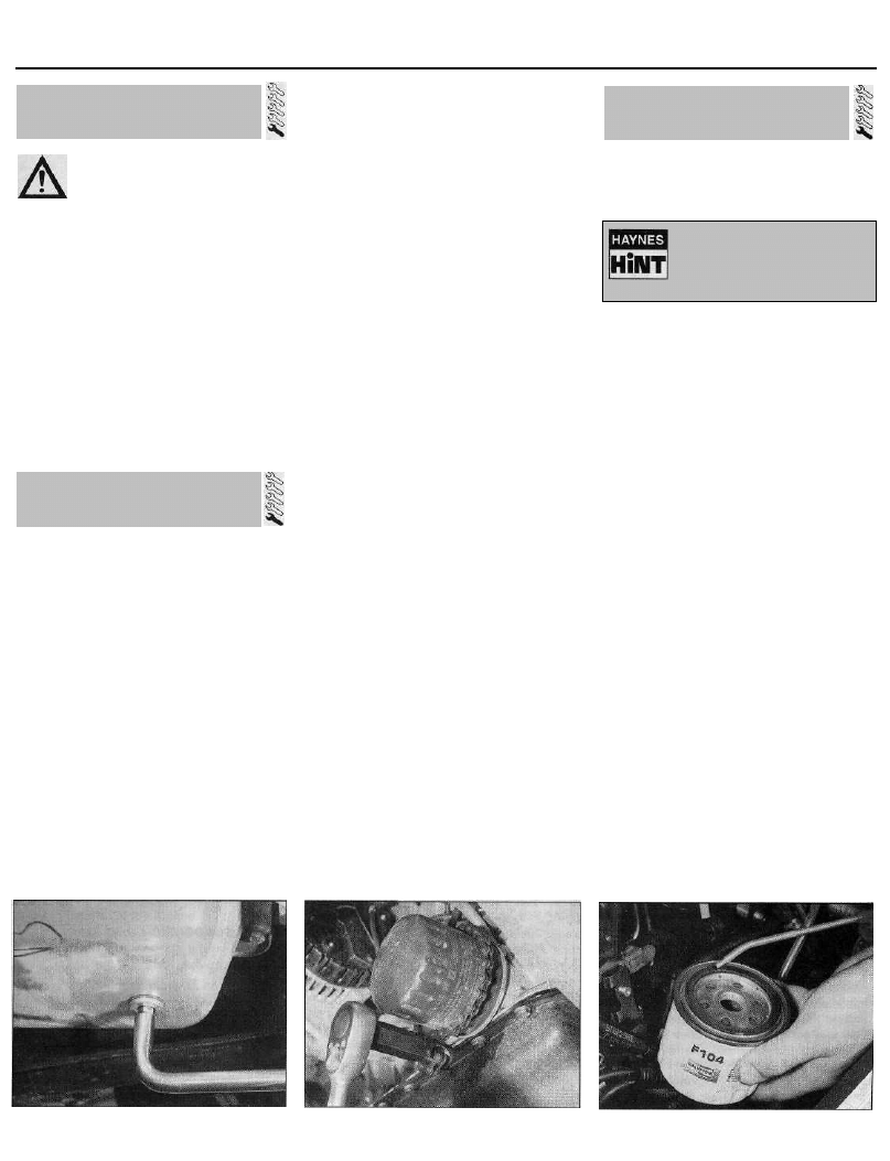
sleeve! Recover the sealing ring from the drain
plug.
4 Allow some time for the old oil to drain,
noting that it may be necessary to reposition
the container as the oil flow slows to a trickle.
5 After all the oil has drained, wipe off the
drain plug with a clean rag, and renew the
sealing washer. Clean the area around the
drain plug opening, and refit the plug. Tighten
the plug securely.
6 If the filter is also to be renewed, move the
container into position under the oil filter,
which is located on the front side of the
cylinder block, below the inlet manifold.
7 Using an oil filter removal tool, slacken the
filter initially, then unscrew it by hand the rest
of the way (see illustration). Empty the oil in
the old filter into the container.
8 Use a clean rag to remove all oil, dirt and
sludge from the filter sealing area on the
engine. Check the old filter to make sure that
the rubber sealing ring hasn't stuck to the
engine. If it has, carefully remove it.
9 Apply a light coating of clean engine oil to
the sealing ring on the new filter, then screw it
into position on the engine (see illustration).
Tighten the filter firmly by hand only - do not
8.3 Slackening the sump drain plug
(1905 cc model shown)
8.7 Using an oil filter removal tool to
slacken the oil filter (1360 cc model shown)
8.9 Lubricate the oil filter sealing ring
before fitting
1•11
8 Engine oil and filter renewal
For maximum clarity of vision,
wiper blades should be
renewed annually, as a matter
of course.
Every 6000 miles
use any tools. Follow the tightening
instructions printed on the filter, if applicable.
10 Remove the old oil and all tools from
under the car, then (if applicable) lower the car
to the ground.
11 Remove the dipstick, then unscrew the oil
filler cap from the filler/breather neck or
cylinder head cover (as applicable). Fill the
engine, using the correct grade and type of oil
(refer to "Lubricants fluids and capacities"). An
oil can spout or funnel may help to reduce
spillage. Pour in half the specified quantity of
oil first, then wait a few minutes for the oil to
run down to the sump. Continue adding oil, a
small quantity at a time, until the level is up to
the lower mark on the dipstick. Adding a
further 1.5 litres (models without air
conditioning) or 1.3 litres (models with air
conditioning), will bring the level up to the
upper mark on the dipstick. Refit the filler cap.
12 Start the engine, and run it for a few
minutes, checking for leaks around the oil
filter seal and the sump drain plug. Note that
there may be a delay of a few seconds before
the low oil pressure warning light goes out
when the engine is first started. The oil takes
time to circulate through the new oil filter and
the engine oil galleries before the pressure
builds up. Do not rev the engine while the
warning light is on.
13 Switch off the engine, and wait a few
minutes for the oil to settle in the sump once
more. With the new oil circulated and the filter
now completely full, recheck the level on the
dipstick, and add more oil as necessary.
14 Dispose of the used engine oil and filter
safely, with reference to "General repair
procedures" in the reference Sections of this
manual.
Note: It is
antisocial and
illegal to dump
oil down the
drain. To find
the location of
your local oil
recycling
bank, call this
number free.
0800 66 33 66
9 Hose and fluid leak check
1 Visually inspect the engine joint faces,
gaskets and seals for any signs of water, oil or
fuel leaks. Pay particular attention to the areas
around the camshaft cover, cylinder head, oil
filter and sump joint faces. Bear in mind that,
over a period of time, some very slight
seepage from these areas is to be expected.
What you are really looking for is any
indication of a serious leak. Should a leak be
found, renew the offending gasket or oil seal
by referring to the appropriate Chapters in this
manual.
2 Also check the security and condition of all
the engine-related pipes and hoses. Ensure
that all cable ties or securing clips are in place
and in good condition. Clips which are broken
or missing can lead to chafing of the hoses,
pipes, or wiring, which could cause more
serious problems in the future.
3 Carefully check the radiator hoses and
heater hoses along their entire length. Renew
any hose which is cracked, swollen, or
deteriorated. Cracks will show up better if the
hose is squeezed. Pay close attention to the
hose clips that secure the hoses to the cooling
system components. Hose clips can pinch and
puncture hoses, resulting in cooling system
leaks. If the original Citroen crimped-type hose
clips are used, it may be a good idea to replace
them with standard worm-drive hose clips.
4 Inspect all the cooling system components
(hoses, joint faces, etc.) for leaks. A leak in the
cooling system will usually show up as white
or rust-coloured deposits on the area
adjoining the leak. Where any problems of this
nature are found on system components,
renew the component or gasket with
reference to Chapter 3.
5 Where applicable, inspect the automatic
transmission fluid cooler hoses for leaks or
deterioration.
6 With the vehicle raised, inspect the petrol
tank and filler neck for punctures, cracks, and
other damage. The connection between the
filler neck and tank is especially critical.
Sometimes, a rubber filler neck or connecting
hose will leak due to loose retaining clamps or
deteriorated rubber.
7 Carefully check all rubber hoses and metal
fuel lines leading away from the petrol tank.
Check for loose connections, deteriorated
hoses, crimped lines, and other damage. Pay
particular attention to the vent pipes and
hoses, which often loop up around the filler
neck, and can become blocked or crimped.
Follow the lines to the front of the vehicle,
carefully inspecting them all the way. Renew
damaged sections as necessary.
8 From within the engine compartment,
check the security of all fuel hose attachments
and pipe unions, and inspect the fuel hoses
and vacuum hoses for kinks, chafing and
deterioration.
1 Take the vehicle on a short journey, to
warm the transmission up to normal operating
temperature, then park the vehicle on level
ground. The fluid level is checked using the
dipstick located at the front of the engine
compartment, directly in front of the
engine/transmission. The dipstick top is
brightly-coloured (usually orange) for easy
identification.
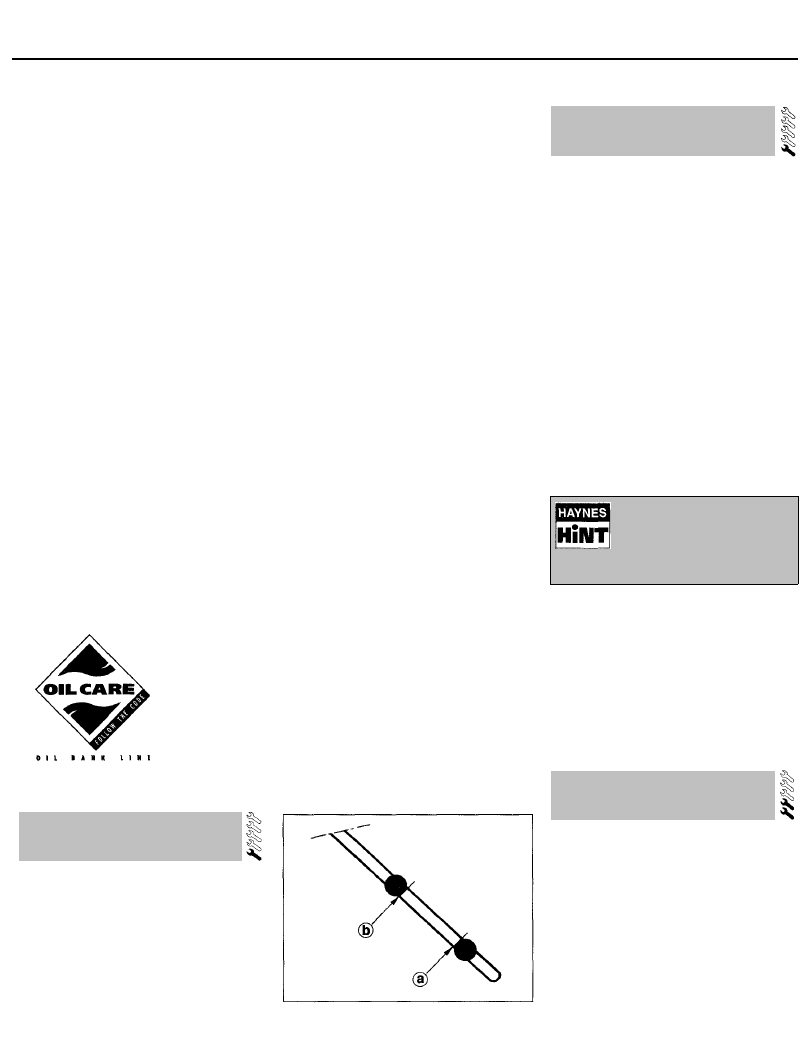
2 With the engine idling and the selector lever
in the "P" (Park) position, withdraw the
dipstick from the tube, and wipe all the fluid
from its end with a clean rag or paper towel.
Insert the clean dipstick back into the tube as
far as it will go, then withdraw it once more.
Note the fluid level on the end of the dipstick;
it should be between the upper and lower
marks (see illustration).
3 If topping-up is necessary, add the required
quantity of the specified fluid to the
transmission via the dipstick tube. Note:
A/ever overfill the transmission so that the fluid
level is above the upper mark.
4 After topping-up, take the vehicle on a
short run to distribute the fresh fluid, then
recheck the level again, topping-up if
necessary.
5 Always maintain the level between the two
dipstick marks. If the level is allowed to fall
below the lower mark, fluid starvation may
result, which could lead to severe
transmission damage.
6 Frequent need for topping-up indicates that
there is a leak, which should be found and
corrected before it becomes serious.
11 Steering and suspension
check
10.2 Automatic transmission fluid dipstick
lower (a) and upper (b) fluid level markings
Front suspension and steering
check
1 Raise the front of the vehicle, and securely
support it on axle stands.
2 Visually inspect the balljoint dust covers
and the steering rack-and-pinion gaiters for
splits, chafing or deterioration (see
illustration). Any wear of these components
will cause loss of lubricant, together with dirt
and water entry, resulting in rapid
deterioration of the balljoints or steering gear.
3 On vehicles with power steering, check the
fluid hoses for chafing or deterioration, and
the pipe and hose unions for fluid leaks. Also
1•12
10 Automatic transmission
fluid level check
9 Where applicable, check the condition of
the power steering fluid hoses and pipes.
Use a funnel with a fine mesh
gauze to avoid fluid spillage,
and to ensure that no foreign
matter enters the
transmission
Every 6000 miles
11.2 Checking a steering gear gaiter
check for signs of fluid leakage under
pressure from the steering gear rubber
gaiters, which would indicate failed fluid seals
within the steering gear.
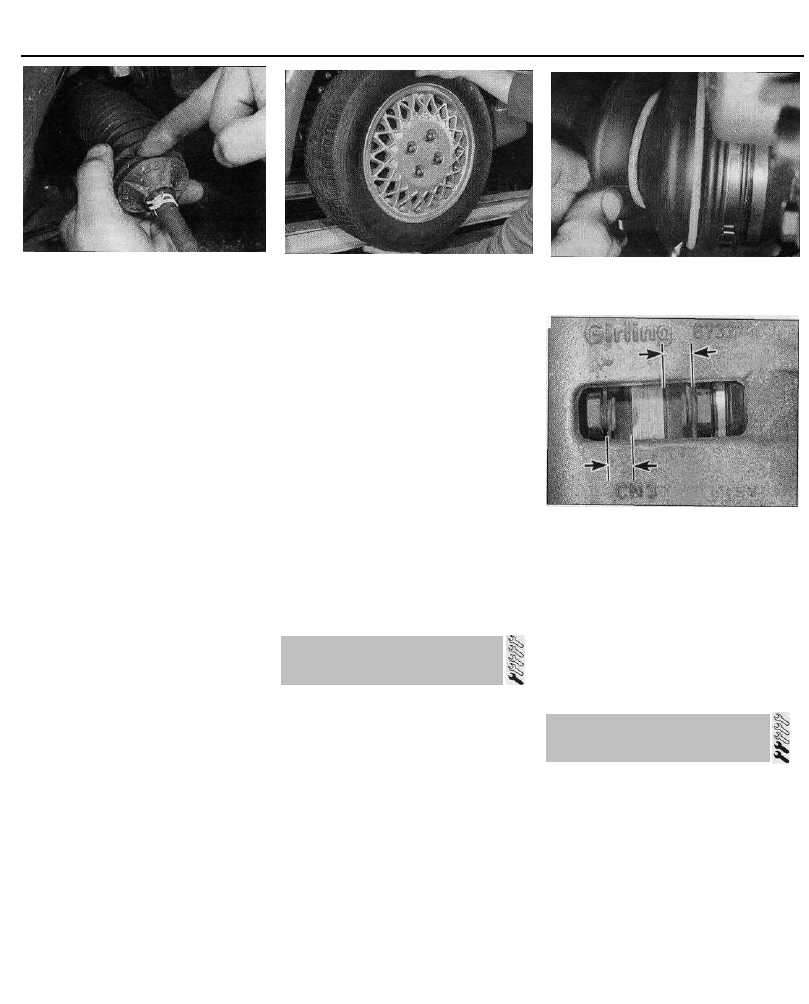
4 Grasp the roadwheel at the 12 o'clock and
6 o'clock positions, and try to rock it (see
illustration). Very slight free play may be felt,
but if the movement is appreciable, further
investigation is necessary to determine the
source. Continue rocking the wheel while an
assistant depresses the footbrake. If the
movement is now eliminated or significantly
reduced, it is likely that the hub bearings are
at fault. If the free play is still evident with the
footbrake depressed, then there is wear in the
suspension joints or mountings.
5 Now grasp the wheel at the 9 o'clock and
3 o'clock positions, and try to rock it as before.
Any movement felt now may again be caused
by wear in the hub bearings or the steering
track-rod balljoints. If the outer balljoint is
worn, the visual movement will be obvious. If
the inner joint is suspect, it can be felt by
placing a hand over the rack-and-pinion
rubber gaiter and gripping the track-rod. If the
wheel is now rocked, movement will be felt at
the inner joint if wear has taken place.
6 Using a large screwdriver or flat bar, check
for wear in the suspension mounting bushes by
levering between the relevant suspension
component and its attachment point. Some
movement is to be expected, as the mountings
are made of rubber, but excessive wear should
be obvious. Also check the condition of any
visible rubber bushes, looking for splits, cracks
or contamination of the rubber.
7 With the car standing on its wheels, have an
assistant turn the steering wheel back and
forth, about an eighth of a turn each way.
There should be very little, if any, lost
movement between the steering wheel and
roadwheels. If this is not the case, closely
observe the joints and mountings previously
described. In addition, check the steering
column universal joints for wear, and also
check the rack-and-pinion steering gear itself.
11.4 Rocking the roadwheel to check
steering/suspension components
Suspension strut/shock absorber
check
8 Check for any signs of fluid leakage around
the suspension strut/shock absorber body, or
from the rubber gaiter around the piston rod.
Should any fluid be noticed, the suspension
strut/shock absorber is defective internally,
and should be renewed. Note: Suspension
struts/shock absorbers should always be
renewed in pairs on the same axle.
9 The efficiency of the suspension
strut/shock absorber may be checked by
bouncing the vehicle at each corner.
Generally speaking, the body will return to its
normal position and stop after being
depressed. If it rises and returns on a
rebound, the suspension strut/shock
absorber is probably suspect. Examine also
the suspension strut/shock absorber upper
and lower mountings for any signs of wear.
12 Drivesshaft gaiter check
Driveshaft rubber gaiter and CV
joint check
1 With the vehicle raised and securely
supported on stands, turn the steering onto
full lock, then slowly rotate the roadwheel.
Inspect the condition of the outer constant
velocity (CV) joint rubber gaiters, while
squeezing the gaiters to open out the folds
(see illustration). Check for signs of cracking,
splits, or deterioration of the rubber, which
may allow the grease to escape, and lead to
water and grit entry into the joint. Also check
the security and condition of the retaining
clips. Repeat these checks on the inner CV
joints. If any damage or deterioration is found,
the gaiters should be renewed without delay
as described in Chapter 8.
2 At the same time, check the general
condition of the CV joints themselves, by first
12.1 Checking driveshaft outer constant
velocity (CV) joint gaiter
13.2 Front brake friction material can be
checked through slot in caliper body -
Girling caliper shown
holding the driveshaft and attempting to
rotate the wheel. Repeat this check by holding
the inner joint and attempting to rotate the
driveshaft. Any appreciable movement
indicates wear in the joints, wear in the
driveshaft splines, or a loose driveshaft
retaining nut.
13 Front brake pad condition
check
1 Firmly apply the handbrake, then jack up
the front of the car and support it securely on
axle stands. Remove the front roadwheels.
2 For a quick check, the thickness of friction
material remaining on each brake pad can be
measured through the slot in the caliper body
(see illustration). If any pad's friction material
is worn to the specified minimum thickness or
less, all four pads must be renewed as a set.
3 For a comprehensive check, the brake pads
should be removed and cleaned. This will
permit the operation of the caliper to be
checked, and the condition of the brake disc
itself to be fully examined on both sides. Refer
to Chapter 9 for further information.
1•13
Every 12 000 miles
Every 12 000 miles or 12 months
14 Air conditioning system
refrigerant check
Warning: Do not attempt to open
the refrigerant circuit. Refer to the
precautions given in Chapter 3.
1 In order to check the condition of the
refrigerant, a humidity indicator and a sight
glass are provided on top of the drier bottle,
which is located at the front right-hand corner
of the engine compartment.
Refrigerant humidity check
2 Check the colour of the humidity indicator
(see illustration). Blue indicates that the
condition of the refrigerant is satisfactory. Red
indicates that the refrigerant is saturated with
humidity. If the indicator shows red, the
system should be drained and recharged, and
a new drier bottle should be fitted. Note: The
system should be drained and recharged only
by a Citroen dealer or air conditioning
specialist. Do not attempt to carry out the
work yourself.
Refrigerant flow check
3 Run the engine, and switch on the air
conditioning.
4 After a few minutes, inspect the sight glass,
and check the fluid flow. Clear fluid should be
visible - if not, the following will help to
diagnose the problem:
(a) Clear fluid flow, perhaps with occasional
bubbles - the system is functioning
correctly.
(b) No fluid flow - have the system checked
for leaks by a Citroen dealer or air
conditioning specialist.
(c) Continuous stream of clear air bubbles in
fluid - refrigerant level low. Have the
system recharged by a Citroen dealer or
air-conditioning specialist.
(d) Milky air bubbles visible - high humidity
(see paragraph 2).
5 Do not operate the air conditioning system
if the refrigerant level is known to be low;
damage may result.
15 Valve clearance check and
adjustment -
1124 cc and 1360 cc models
Note: The valve clearances must be checked
and adjusted only when the engine is cold.
Note: The manufacturer suggests this operation
at the first 12 000 mile service only. After that,
checking and adjusting of the valve clearances
is not part of the recommended maintenance
schedule. The operation should therefore only
need to be carried out after engine overhaul, or
when investigating noise or power loss which
could be attributed to the valve gear.
1 The importance of having the valve
clearances correctly adjusted cannot be
overstressed, as they vitally affect the
performance of the engine. If the clearances
are too big, the engine will be noisy
(characteristic rattling or tapping noises) and
engine efficiency will be reduced, as the
valves open too late and close too early. A
more serious problem arises if the clearances
are too small, however. If this is the case, the
valves may not close fully when the engine is
hot, resulting in serious damage to the engine
(eg. burnt valve seats and/or cylinder head
warping/cracking). The clearances are
checked and adjusted as follows.
2 Remove the cylinder head cover as
described in Chapter 2A.
3 The engine can now be turned using a
suitable socket and extension bar fitted to the
crankshaft sprocket/pulley bolt.
4 It is important that the clearance of each
valve is checked and adjusted only when the
valve is fully closed, with the rocker arm resting
on the heel of the cam (directly opposite the
peak). This can be ensured by carrying out the
adjustments in the following sequence, noting
that No 1 cylinder is at the transmission end of
the engine. The correct valve clearances are
given in the Specifications at the end of this
Chapter. The valve locations can be
determined from the position of the manifolds.
Valve fully
open Adjust valves
No 1 exhaust No 3 inlet and No 4 exhaust
No 3 exhaust No 4 inlet and No 2 exhaust
No 4 exhaust No 2 inlet and No 1 exhaust
No 2 exhaust No 1 inlet and No 3 exhaust
5 With the relevant valve fully open, check the
clearances of the two valves specified.
Clearances are checked by inserting a feeler
gauge of the correct thickness between the
valve stem and the rocker arm adjusting screw.
The feeler gauge should be a light, sliding fit. If
adjustment is necessary, slacken the adjusting
screw locknut, and turn the screw as necessary.
Once the correct clearance is obtained, hold the
adjusting screw and securely tighten the locknut
(see illustration). Recheck the valve clearance,
and adjust again if necessary.
6 Rotate the crankshaft until the next valve in
the sequence is fully open, and check the
clearances of the next two specified valves.
7 Repeat the procedure until all eight valve
clearances have been checked (and if
necessary, adjusted), then refit the cylinder
head cover as described in Chapter 2A.
16 Spark plug renewal
1 The correct functioning of the spark plugs is
vital for the correct running and efficiency of
the engine. It is essential that the plugs fitted
are appropriate for the engine (the suitable type
is specified at the end of this Chapter). If this
type is used, and the engine is in good
condition, the spark plugs should not need
attention between scheduled replacement
intervals. Spark plug cleaning is rarely
necessary, and should not be attempted unless
specialised equipment is available, as damage
can easily be caused to the firing ends.
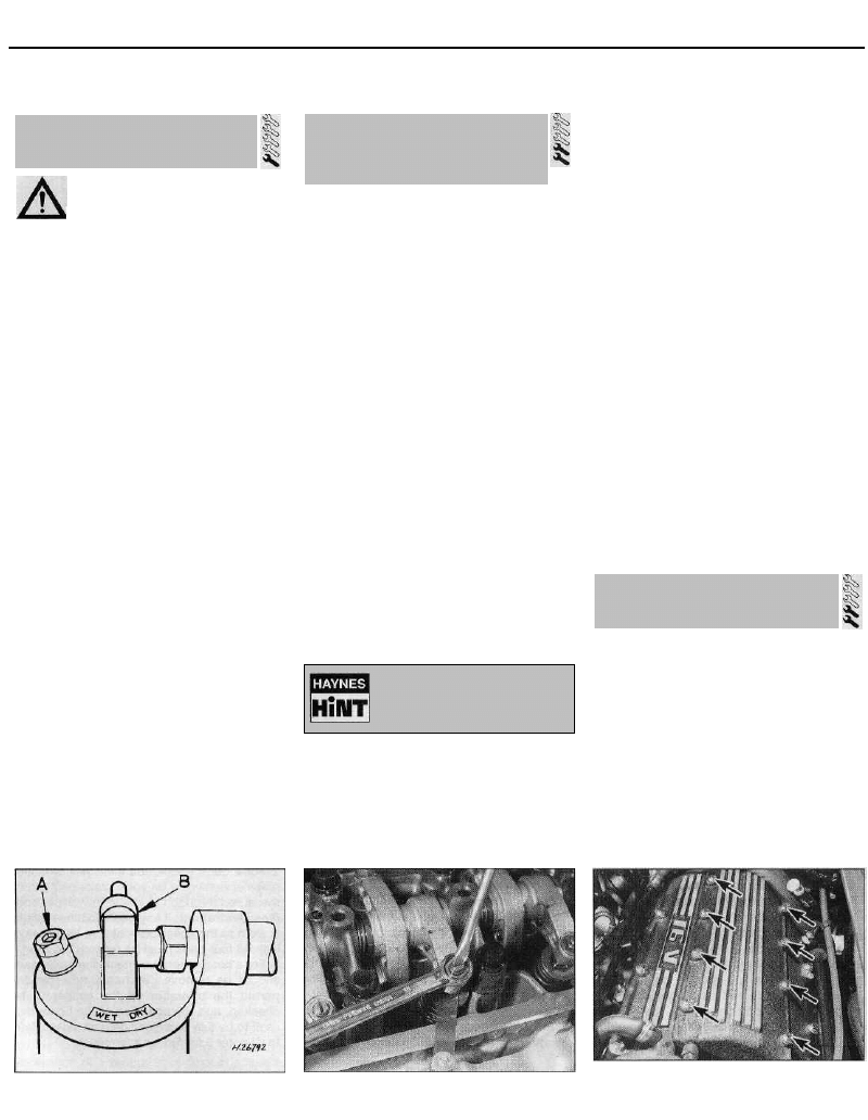
2 On 1998 cc 16-valve models, to gain
access to the spark plugs, the access cover
14.2 Air conditioning system refrigerant
humidity indicator (A) and sight glass (B)
15.5 Adjusting a valve clearance -1124 cc
and 1360 cc models
16.2 On 1998 cc 16-valve models, undo
the eight bolts (arrowed) and remove the
access cover to reach the spark plugs
1•14
Turning the engine will be
easier if the spark plugs are
removed.
Every 12 000 miles
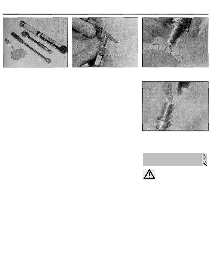
16.7 Tools required for spark plug
removal, gap adjustment and refitting
fitted in the centre of the cylinder head cover
must first be removed. Undo the eight bolts,
noting the position of the wiring retaining clip,
and remove the cover (see illustration).
3 On some other models, to improve access
to some of the plugs, it may be necessary to
remove the air intake duct (refer to Chapter 4
for further information).
4 On 1998 cc 16-valve models, pull the HT
coils off the spark plugs. If necessary, to
remove the possibility of the HT coils being
connected to the wrong spark plugs on
refitting, mark the coils 1 to 4 (No 1 cylinder is
at the transmission end of the engine).
5 On all other models, if the marks on the
original-equipment spark plug (HT) leads
cannot be seen, mark the leads 1 to 4,
corresponding to the cylinder the lead serves
(No 1 cylinder is at the transmission end of the
engine). Pull the leads from the plugs by
gripping the end fitting, not the lead, otherwise
the lead connection may be fractured.
6 It is advisable to remove the dirt from the
spark plug recesses, using a clean brush,
vacuum cleaner or compressed air before
removing the plugs, to prevent dirt dropping
into the cylinders.
7 Unscrew the plugs using a spark plug
spanner, suitable box spanner, or a deep
socket and extension bar (see illustration).
Keep the socket aligned with the spark plug -
if it is forcibly moved to one side, the ceramic
insulator may be broken off. As each plug is
removed, examine it as follows.
8 Examination of the spark plugs will give a
good indication of the condition of the engine.
If the insulator nose of the spark plug is clean
and white, with no deposits, this is indicative
of a weak mixture. It could also indicate that
the plug is too "hot" for the engine (a hot plug
transfers heat away from the electrode slowly,
a cold plug transfers heat away quickly). If this
condition is apparent, either correct the
mixture setting (where possible), or ensure
that the correct grade of plug is fitted.
9 If the tip and insulator nose are covered
with hard black-looking deposits, then this is
indicative that the mixture is too rich. Should
the plug be black and oily, then it is likely that
the engine is fairly worn, as well as the mixture
being too rich.
16.12 Measuring the spark plug gap with a
feeler gauge
10 If the insulator nose is covered with light
tan to greyish-brown deposits, then the
mixture is correct, and it is likely that the
engine is in good condition.
11 The spark plug electrode gap is of
considerable importance as, if it is too large or
too small, the size of the spark and its
efficiency will be seriously impaired. The gap
should be set to the value given in the
Specifications at the end of this Chapter.
12 To set it, measure the gap with a feeler
gauge. If necessary, bend the outer plug
electrode open or closed until the correct gap
is achieved (see illustration). The centre
electrode should never be bent, as this may
crack the insulator and cause plug failure, if
nothing worse.
13 Special spark plug electrode gap
adjusting tools are available from most motor
accessory shops (see illustrations).
14 Before fitting the spark plugs, check that
the threaded connector sleeves (on top of the
plug) are tight, and that the plug exterior
surfaces and threads are clean. Apply a smear
of copper-based anti-seize compound to the
plug threads.
15 It is very often difficult to insert spark
plugs into their holes without cross-threading
them. To avoid this possibility, fit a short
length of 5/16 inch/8 mm internal diameter
rubber or plastic hose over the end of the
spark plug. (Flexible fuel hose is ideal.) The
flexible hose acts as a universal joint to help
align the plug with the plug hole. Should the
plug begin to cross-thread, the hose will slip
on the spark plug, preventing thread damage
to the aluminium cylinder head. Once the plug
begins to screw in correctly, remove the hose,
and tighten the plug to the specified torque
using the spark plug socket and a torque
wrench. Refit the remaining spark plugs in the
same manner.
16 On 1998 cc 16-valve models, connect the
HT coils in their correct order, then refit the
access cover to the cylinder head cover. Ensure
that the coil wiring is correctly located in the
cover recess. Refit the cover bolts, not forgetting
the wiring clip, and tighten them securely.
17 On all other models, connect the HT leads
in their correct order, and refit any
components removed for access.
16.13a Measuring the spark plug gap with
a wire gauge . . .
16.13b . . . and adjusting the gap using a
special adjusting tool
Warning: Before carrying out the
following operation, refer to the
precautions given in "Safety
first!" at the beginning of this
manual, and follow them implicitly. Petrol
is a highly-dangerous and volatile liquid,
and the precautions necessary when
handling it cannot be overstressed.
1 The fuel filter is mounted on the centre of
the engine compartment bulkhead, directly
behind the engine.
2 To remove the filter, release the retaining
clips and disconnect the fuel hoses from the
filter. Where the original Citroen crimped-type
hose clips are still fitted, cut the clips and
discard them; use standard worm-drive hose
clips on refitting.
3 Note the direction of the arrow marked on
the filter body. Unclip the filter from its
retaining bracket, and remove it from the
vehicle.
4 Dispose safely of the old filter; it will be
highly-inflammable, and may explode if
thrown on a fire.
5 Connect the fuel hoses to the new filter.
Make sure that the arrow on the filter body is
pointing in the direction of the fuel flow, ie.
1•15
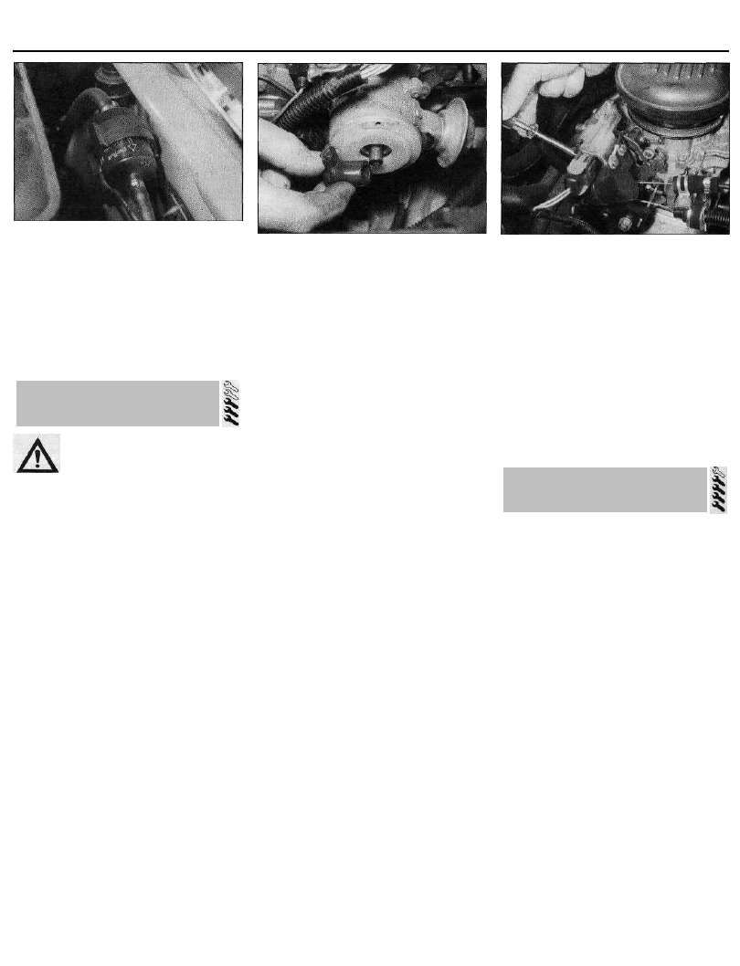
17 Fuel filter renewal -
carburettor models
Every 12 000 miles
17.5 On carburettor models, ensure that
the arrow on the fuel filter body points in
the direction of fuel flow
towards the fuel pump (see illustration).
Secure the hoses in position by securely
tightening the retaining clips, then clip the
filter back into position in its retaining bracket.
6 Start the engine, and check the filter hose
connections for leaks.
18 Ignition system check
Warning: Voltages produced by
an electronic ignition system are
considerably higher than those
produced by conventional ignition
systems. Extreme care must be taken if
working on the system with the ignition
switched on. Persons with surgically-
implanted cardiac pacemaker
devices should keep well clear of the
ignition circuits, components and test
equipment.
1 The ignition system components should be
checked for damage or deterioration as
described under the relevant sub-heading.
Ignition systems incorporating a
distributor
General component check
2 The spark plug (HT) leads should be
checked whenever new spark plugs are
installed in the engine.
3 Ensure that the leads are numbered before
removing them, to avoid confusion when
refitting. Pull the leads from the plugs by
gripping the end fitting, not the lead,
otherwise the lead connection may be
fractured.
4 Check inside the end fitting for signs of
corrosion, which will look like a white crusty
powder. Push the end fitting back onto the
spark plug, ensuring that it is a tight fit on the
plug. If not, remove the lead again, and use
pliers to carefully crimp the metal connector
inside the end fitting until it fits securely on the
end of the spark plug.
5 Using a clean rag, wipe the entire length of
the lead to remove any built-up dirt and
grease. Once the lead is clean, check for
18.9 The rotor arm is a push fit on the
distributor shaft (1360 cc model shown)
burns, cracks and other damage. Do not bend
the lead excessively, or pull the lead
lengthwise - the conductor inside might
break.
6 Disconnect the other end of the lead from
the distributor cap. Again, pull only on the end
fitting. Check for corrosion and a tight fit in the
same manner as the spark plug end. If an
ohmmeter is available, check the resistance of
the lead by connecting the meter between the
spark plug end of the lead and the segment
inside the distributor cap. Refit the lead
securely on completion.
7 Check the remaining leads one at a time, in
the same way.
8 If new spark plug (HT) leads are required,
purchase a set for your specific car and
engine.
9 Remove the distributor cap by unscrewing
its retaining screws. Wipe it clean, and
carefully inspect it inside and out for signs of
cracks, carbon tracks (tracking) and worn,
burned or loose contacts; check that the
cap's carbon brush is unworn, free to move
against spring pressure, and making good
contact with the rotor arm. Also inspect the
cap seal for signs of wear or damage, and
renew if necessary. Remove the rotor arm
from the distributor shaft and inspect it (see
illustration). It is common practice to renew
the cap and rotor arm whenever new spark
plug (HT) leads are fitted. When fitting a new
cap, remove the leads from the old cap one at
a time, and fit them to the new cap in the
exact same location - do not simultaneously
remove all the leads from the old cap, or firing
order confusion may occur. On refitting,
ensure that the arm is securely pressed onto
the shaft, and tighten the cap retaining screws
securely.
10 Even with the ignition system in first class
condition, some engines may still occasionally
experience poor starting, attributable to damp
ignition components. A moisture dispersant
spray can be very effective.
Ignition timing checking and
adjustment
11 Check the ignition timing as described in
Chapter 5, Section 10.
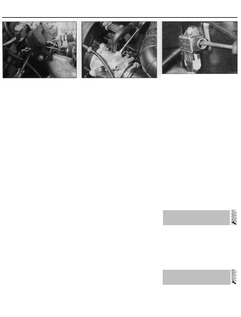
19.4 Adjusting the idle speed -1360 cc
carburettor models
Static (distributorless) ignition
systems
General component check
12 On all except 1998 cc 16-valve models,
check the condition of the HT leads as
described above in paragraphs 3 to 8. On
1998 cc 16-valve models, there are no HT
leads, so the only relevant check is that all the
primary (LT) circuit wiring connectors are
clean and free of corrosion.
Ignition timing check and adjustment
13 Refer to Chapter 5, Section 10.
19 Idle speed and mixture
check and adjustment
1 Before checking the idle speed and mixture
setting, always check the following first:
(a) Check that the ignition timing is accurate
(Chapter 5).
(b) Check that the spark plugs are in good
condition and correctly gapped (Sec-
tion 16).
(c) Check that the accelerator cable (and on
carburettor models, the choke cable) is
correctly adjusted (refer to the relevant
Part of Chapter 4).
(d) Check that the crankcase breather hoses
are secure, with no leaks or kinks (Sec-
tion 20).
(e) Check that the air cleaner filter element is
clean (Section 26).
(f) Check that the exhaust system is in good
condition (refer to the relevant Part of
Chapter 4).
(g) If the engine is running very roughly,
check the compression pressures as
described in Chapter 2.
(h) On fuel injection models, check that the
fuel injection/ignition system warning light
is not illuminated (refer to the relevant
Part of Chapter 4).
2 Take the car on a journey of sufficient'
length to warm it up to normal operating
temperature. Note: Adjustment should ideally
be completed within two minutes of return,
without stopping the engine. If the radiator
electric cooling fan operates, wait for the
cooling fan to stop. If adjustment takes longer
1•16
Every 12 000 miles
19.7 Adjusting the idle mixture (exhaust
gas CO level) - 1360 cc carburettor models
than stated, regularly clear any excess fuel
from the inlet manifold by revving the engine
two or three times to between 2000 and 3000
rpm, then allow it to idle again.
Carburettor models
3 Ensure that all electrical loads are switched
off, and that the choke lever is pushed fully in.
If the car does not have a tachometer,
connect one following its manufacturer's
instructions. Note the idle speed, and
compare it with that specified.
4 The idle speed adjusting screw is on the
throttle linkage on the right-hand side of the
carburettor. On 1124 cc models, the screw is
easily accessible from above; on 1360 cc
models, the screw is adjusted from behind the
carburettor, and access is a little awkward.
Using a suitable flat-bladed screwdriver,
screw it in (to increase the speed) or out as
necessary to obtain the specified speed (see
illustration).
5 The idle mixture (exhaust gas CO level) is
set at the factory, and should require no
further adjustment. If, due to a change in
engine characteristics (carbon build-up, bore
wear etc) or after a major carburettor
overhaul, the mixture becomes incorrect, it
can be reset. Note, however, that an exhaust
gas analyser (CO meter) will be required to
check the mixture, and to set it with the
necessary standard of accuracy. If this is not
available, the car must be taken to a Citroen
dealer for the work to be carried out.
6 If an exhaust gas analyser is available,
follow the manufacturer's instructions to
check the exhaust gas CO level. If adjustment
is required, it is made via mixture adjustment
screw. On 1124 cc models, the screw is
located on the left-hand side of the
carburettor base; on 1360 cc models, it is
located at the right-hand rear corner of the
carburettor base. The screw is covered with a
tamperproof plug to prevent unnecessary
adjustment. To gain access to the screw, use
a sharp instrument to hook out the plug.
7 Using a suitable flat-bladed screwdriver,
turn the mixture adjustment screw by very
small amounts until the level is correct.
Screwing it in (clockwise) weakens the idle
mixture and reduces the CO level; screwing it
19.10 Adjusting the idle speed - 1905 cc
models
out will richen the mixture and increase the
CO level (see illustration).
8 When adjustments are complete,
disconnect any test equipment, and fit a new
tamperproof plug to the mixture adjustment
screw. Recheck the idle speed and, if
necessary, readjust.
Fuel injection models
1905 cc models
9 Ensure that all electrical loads are switched
off. If the car does not have a tachometer,
connect one following its manufacturer's
instructions. Note the idle speed, and
compare it with that specified.
10 The idle speed adjusting screw is situated
in the top of the throttle housing. Using a
suitable flat-bladed screwdriver, screw it in or
out as necessary to obtain the specified
speed (see illustration).
11 On models with a catalytic converter
(DKZ engine with Motronic M1.3 system) the
idle mixture (exhaust gas CO level) is under
the control of the engine management ECU,
and is not adjustable (see paragraph 18).
12 On models without a catalytic converter
(D6E engine with Motronic MP3.1 system), the
idle mixture can be adjusted if necessary. The
idle mixture is set at the factory, however, and
should not normally require adjustment. If,
due to a change in engine characteristics
(carbon build-up, bore wear etc) or after a
major overhaul, the mixture becomes
incorrect, it can be reset. An exhaust gas
analyser (CO meter) will be required to check
the mixture, and to set it with the necessary
standard of accuracy. If this is not available,
the car must be taken to a Citroen dealer for
the work to be carried out.
13 If an exhaust gas analyser is available,
follow its manufacturer's instructions to check
the exhaust gas CO level. If adjustment is
required, it is made using the screw on the
mixture adjustment potentiometer. This is
mounted on the side of the engine
management ECU, in the left-hand rear corner
of the engine compartment.
14 Using a suitable flat-bladed screwdriver,
turn the screw in very small increments until
the level is correct (see illustration).
19.14 Adjusting the idle mixture (exhaust
gas CO level) - 1905 cc models without a
catalytic converter
15 When adjustments are complete,
disconnect any test equipment. Recheck the
idle speed and, if necessary, readjust.
All other models
16 Experienced home mechanics, with a
considerable amount of skill and equipment
(including a tachometer and an accurate
exhaust gas analyser) may be able to check
the exhaust CO level and the idle speed.
However, if these are found to be in need of
adjustment, the car must be taken to a
suitably-equipped Citroen dealer.
17 On 1580 cc models, adjustment of the
mixture setting (exhaust gas CO level) is
possible, but adjustments can only be made
by reprogramming the engine management
ECU, using special electronic test equipment
which is connected to the diagnostic wiring
connector (see Chapter 4B).
18 On all other vehicles, adjustments are not
possible. If the idle speed or the exhaust gas
CO level is incorrect, then there must be a
fault in the engine management system; the
vehicle should be taken to a Citroen dealer for
testing (refer to the relevant Part of Chapter 4).
20 Emission control systems
check
1 Details of the emission control system
components are given in Chapter 4D.
2 Checking consists simply of a visual check
for obvious signs of damaged or leaking
hoses and joints.
3 Detailed checking and testing of the
evaporative and/or exhaust emission systems
(as applicable) should be entrusted to a
Citroen dealer.
1 On 1580 cc and 1905 cc models with air
conditioning, two auxiliary drivebelts are
fitted; one for the air conditioning compressor,
and another for the power steering pump
and/or alternator (as applicable). On all other
models there is only one auxiliary drivebelt.
1•17
21 Auxiliary drivebelt checking
and renewal
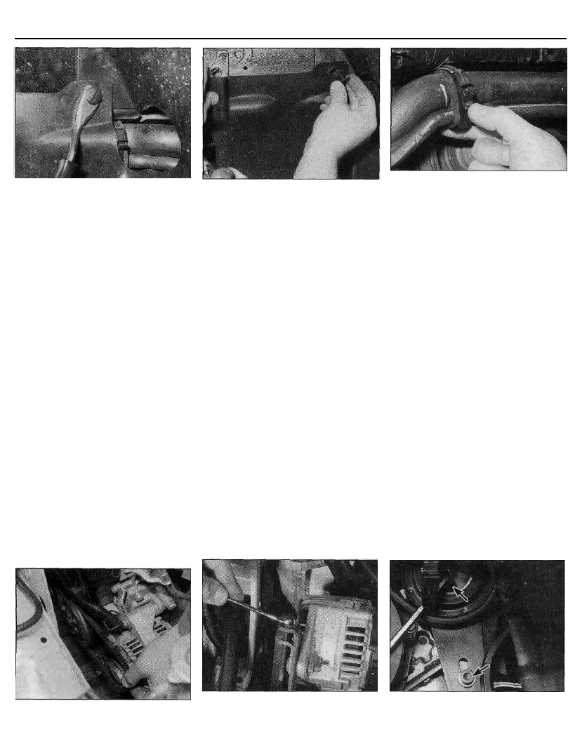
Every 12 000 miles
21.3a Prise out the retaining clips . . .
Checking the auxiliary drivebelt
condition
2 Apply the handbrake, then jack up the front
of the car and support it on axle stands.
Remove the right-hand front roadwheel.
3 From underneath the front of the car, prise
out the two retaining clips, and remove the
plastic cover from the wing valance to gain
access to the crankshaft sprocket/pulley bolt.
Where necessary, unclip the coolant hoses
from the bracket to improve access further
(see illustrations).
4 Using a suitable socket and extension bar
fitted to the crankshaft sprocket/pulley bolt,
rotate the crankshaft so that the entire length
of the drivebelt(s) can be examined. Examine
the drivebelt(s) for cracks, splitting, fraying or
damage. Check also for signs of glazing (shiny
patches) and for separation of the belt plies.
Renew the belt if worn or damaged.
5 If the condition of the belt is satisfactory, on
models where the belt is adjusted manually,
check the drivebelt tension as described
below. On models with an automatic spring-
loaded tensioner, there is no need to check
the drivebelt tension.
Auxiliary drivebelt (models with
manual adjuster on the alternator
lower mounting point) - removal,
refitting and tensioning
Removal
6 If not already done, proceed as described
21.3b . . . and remove the plastic cover
from underneath the wheel arch . . .
in paragraphs 2 and 3. On 1580 cc and
1905 cc models with air conditioning, remove
the air conditioning drivebelt as described in
paragraphs 40 to 42.
7 Disconnect the battery negative lead.
8 Slacken both the alternator upper and lower
mounting nuts/bolts (as applicable).
9 Back off the adjuster bolt(s) to relieve the
tension in the drivebelt, then slip the drivebelt
from the pulleys (see illustration).
Refitting
10 If the belt is being renewed, ensure that
the correct type is used. Fit the belt around
the pulleys, and take up the slack in the belt
by tightening the adjuster bolt.
11 Tension the drivebelt as described in the
following paragraphs. On 1580 cc and
1905 cc models, where necessary, refit the air
conditioning compressor drivebelt as
described in paragraphs 43 to 49.
Tensioning
12 If not already done, proceed as described
in paragraphs 2 and 3.
13 Correct tensioning of the drivebelt will
ensure that it has a long life. A belt which is
too slack will slip and perhaps squeal.
Beware, however, of overtightening, as this
can cause wear in the alternator bearings.
14 The belt should be tensioned so that,
under firm thumb pressure, there is
approximately 5.0 mm of free movement at
21.3c Where necessary, unclip the coolant
hoses to improve access to the crankshaft
pulley/sprocket bolt
the mid-point between the pulleys on the
longest belt run.
15 To adjust, with the upper mounting
nut/bolt just holding the alternator firm, and
the lower mounting nut/bolt loosened, turn the
adjuster bolt until the correct tension is
achieved (see illustration). Rotate the
crankshaft a couple of times, recheck the
tension, then securely tighten both the
alternator mounting nuts/bolts. Where
applicable, also tighten the bolt securing the
adjuster strap to its mounting bracket.
16 Reconnect the battery negative lead.
17 Clip the coolant hoses into position
(where necessary), then refit the plastic cover
to the wing valance. Refit the roadwheel, and
lower the vehicle to the ground.
Auxiliary drivebelt (models with a
manually-adjusted tensioning
pulley) - removal, refitting and
tensioning
Note: For information on the air conditioning
compressor drivebelt on 1580 cc and 1905 cc
models, refer to paragraphs 40 to 49.
Removal
18 If not already done, proceed as described
in paragraphs 2 and 3.
19 Disconnect the battery negative lead.
20 Slacken the two screws securing the
tensioning pulley assembly to the engine (see
illustration).
21 Rotate the adjuster bolt to move the
21.9 Removing the drivebelt - 1360 cc
models
21.15 Adjusting the drivebelt tension -
drivebelt adjuster on lower alternator
mounting point (1905 cc model shown)
21.20 On models with a manually-adjusted
tensioner pulley, slacken the two pulley
retaining screws (arrowed)...
1•18
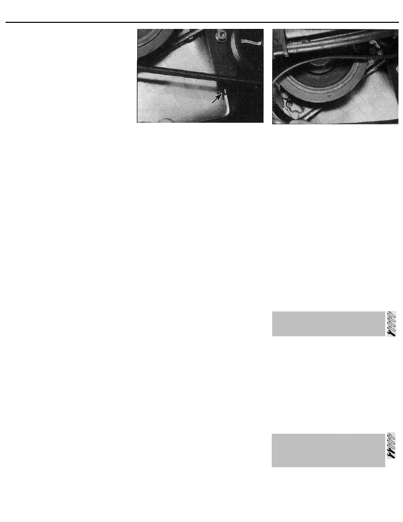
Every 12 000 miles
tensioner pulley away from the drivebelt until
there is sufficient slack for the drivebelt to be
removed from the pulleys (see illustrations).
Refitting
22 Fit the drivebelt around the pulleys in the
following order:
(a) Power steering pump and/or air
conditioning compressor.
(b) Crankshaft.
(c) Alternator.
(d) Tensioner roller.
23 Ensure that the ribs on the belt are
correctly engaged with the grooves in the
pulleys, and that the drivebelt is correctly
routed. Take all the slack out of the belt by
turning the tensioner pulley adjuster bolt.
Tension the belt as follows.
Tensioning
24 If not already done, proceed as described
in paragraphs 2 and 3.
25 Correct tensioning of the drivebelt will
ensure that it has a long life. A belt which is
too slack will slip and perhaps squeal.
Beware, however, of overtightening, as this
can cause wear in the alternator bearings.
26 The belt should be tensioned so that,
under firm thumb pressure, there is
approximately 5.0 mm of free movement at
the mid-point between the pulleys on the
longest belt run.
27 To adjust the tension, with the two
tensioner pulley assembly retaining screws
slackened, rotate the adjuster bolt until the
correct tension is achieved. Once the belt is
correctly tensioned, rotate the crankshaft a
couple of times and recheck the tension.
28 When the belt is correctly tensioned,
securely tighten the tensioner pulley assembly
retaining screws, then reconnect the battery
negative lead.
29 Clip the coolant hoses into position, then
refit the plastic cover to the wing valance.
Refit the roadwheel, and lower the vehicle to
the ground.
Auxiliary drivebelt (models with an
automatic spring-loaded
tensioner pulley) - removal,
refitting and tensioning
Removal
30 If not already done, proceed as described
in paragraphs 2 and 3.
31 Disconnect the battery negative lead.
32 Where necessary, remove the retaining
screws from the power steering pump pulley
shield, and remove the shield to gain access
to the top of the drivebelt.
33 Move the tensioner pulley away from the
drivebelt, using a ratchet handle or extension bar
with the same size square-section end as the
hole in the base of the automatic tensioner arm.
Disengage the drivebelt from all the pulleys,
noting its correct routing. Remove the drivebelt
from the engine, noting that in some cases, it
may be necessary to slacken the automatic
tensioner mounting bolts to disengage the belt
from behind the tensioner pulley.
21.21a . . . then slacken the pulley adjuster
b o l t . . .
Refitting and tensioning
34 Fit the drivebelt around the pulleys in the
following order:
(a) Automatic tensioner pulley.
(b) Crankshaft.
(c) Air conditioning compressor.
(d) Power steering pump.
(e) Idler pulley
(f) Alternator.
35 Where necessary, securely tighten the
automatic tensioner mounting bolts.
36 Whilst holding the tensioner arm away
from the belt, ensure that the ribs on the belt
are correctly engaged with the grooves in the
pulleys. Release the tensioner arm; the
tensioner is spring-loaded, removing the need
to manually adjust the belt tension.
37 Refit the power steering pump pulley
shield (where removed), and securely tighten
its retaining screws.
38 Reconnect the battery negative lead.
39 Clip the coolant hoses into position, then
refit the plastic cover to the wing valance.
Refit the roadwheel, and lower the vehicle to
the ground.
Air conditioning compressor
auxiliary drivebelt (1580 cc and
1905 cc models) - removal,
refitting and tensioning
Removal
40 If not already done, proceed as described
in paragraphs 2 and 3.
41 Disconnect the battery negative lead.
42 Slacken the three bolts securing the
tensioner pulley to the sump, to release the
drivebelt tension, and unhook the drivebelt
from the pulleys.
Refitting
43 Fit the new drivebelt around the pulleys,
ensuring that its ribs are correctly located in
the pulley grooves.
44 Obtain a suitable ratchet handle or
extension bar with the same size square-
section end as one of the holes in the
tensioner arm. Using this, force the tensioner
pulley against the drivebelt to remove the
drivebelt slack. Tension the belt as follows.
Tensioning
45 If not already done, proceed as described
in paragraphs 2 and 3.
21.21 b . . . and slip the drivebelt off its
pulleys
46 Correct tensioning of the drivebelt will
ensure that it has a long life. Beware,
however, of overtightening, as this can cause
wear in the compressor bearings.
47 The belt should be tensioned so that,
under firm thumb pressure, there is
approximately 5.0 mm of free movement at
the mid-point between the pulleys on the top
belt run.
48 To adjust the tension, first slacken the
three tensioner pulley assembly retaining
bolts. Using the ratchet handle or extension
bar described in paragraph 44, force the
tensioner pulley against the drivebelt until the
correct drivebelt tension is obtained. Hold the
pulley in this position, and securely tighten its
three retaining bolts. Rotate the crankshaft a
couple of times, and recheck the tension.
49 When the belt is correctly tensioned, clip
the coolant hoses into position, then refit the
plastic cover to the wing valance. Refit the
roadwheel, and lower the vehicle to the ground.
1 Check that the clutch pedal moves
smoothly and easily through its full travel.
2 The clutch itself should function correctly,
with no trace of slip or drag.
3 Adjust the clutch cable if necessary, as
described in Chapter 6.
4 If excessive effort is required to operate the
clutch, check first that the cable is correctly
routed and undamaged. Remove the pedal,
and make sure that its pivot is properly
greased. Refer to Chapter 6 for further
information.
1 Remove the rear brake drums, and check
the brake shoes for signs of wear or
contamination. At the same time, also inspect
the wheel cylinders for signs of leakage, and
the brake drum for signs of wear. Refer to the
relevant Sections of Chapter 9 for further
information.
1•19
22 Clutch adjustment check and
control mechanism lubrication
23 Rear brake shoe condition
check -
models with rear drum brakes
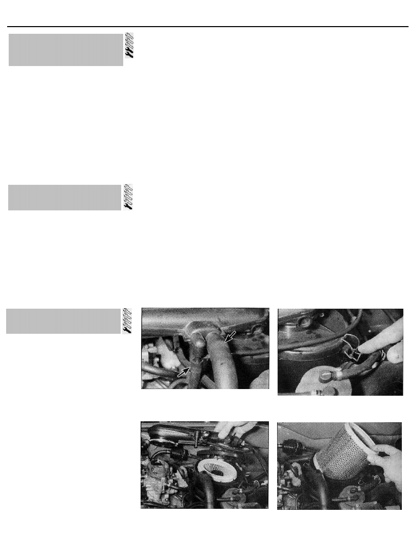
Every 18 000 miles
24 Rear brake pad condition
check -
models with rear disc brakes
1 Chock the front wheels, then jack up the
rear of the vehicle and support it on axle
stands. Remove the rear roadwheels.
2 For a quick check, the thickness of friction
material remaining on each brake pad can be
measured through the top of the caliper body.
If any pad's friction material is worn to the
specified thickness or less, all four pads must
be renewed as a set.
3 For a comprehensive check, the brake pads
should be removed and cleaned. This will
permit the operation of the caliper to be
checked, and the condition of the brake disc
itself to be fully examined on both sides. Refer
to Chapter 9 for further information.
25 Road test
Instruments and electrical
equipment
1 Check the operation of all instruments and
electrical equipment.
2 Make sure that all instruments read
correctly, and switch on all electrical
equipment in turn, to check that it functions
properly.
Steering and suspension
3 Check for any abnormalities in the steering,
suspension, handling or road "feel".
4 Drive the vehicle, and check that there are
no unusual vibrations or noises.
5 Check that the steering feels positive, with
no excessive "sloppiness", or roughness, and
check for any suspension noises when
cornering and driving over bumps.
Drivetrain
6 Check the performance of the engine,
clutch (where applicable), transmission and
driveshafts.
7 Listen for any unusual noises from the
engine, clutch and transmission.
8 Make sure that the engine runs smoothly
when idling, and that there is no hesitation
when accelerating.
9 Check that, where applicable, the clutch
action is smooth and progressive, that the
drive is taken up smoothly, and that the pedal
travel is not excessive. Also listen for any
noises when the clutch pedal is depressed.
10 On manual transmission models, check
that all gears can be engaged smoothly
without noise, and that the gear lever action is
not abnormally vague or "notchy".
11 On automatic transmission models, make
sure that all gearchanges occur smoothly,
without snatching, and without an increase in
engine speed between changes. Check that
all the gear positions can be selected with the
vehicle at rest. If any problems are found, they
should be referred to a Citroen dealer.
12 Listen for a metallic clicking sound from
the front of the vehicle, as the vehicle is driven
slowly in a circle with the steering on full-lock.
Carry out this check in both directions. If a
clicking noise is heard, this indicates wear in a
driveshaft joint, in which case the joint should
be renewed.
Check the operation and
performance of the braking
system
13 Make sure that the vehicle does not pull to
one side when braking, and that the wheels
do not lock prematurely when braking hard.
14 Check that there is no vibration through
the steering when braking.
15 Check that the handbrake operates
correctly, without excessive movement of the
lever, and that it holds the vehicle stationary
on a slope.
16 Test the operation of the brake servo unit
as follows. Depress the footbrake four or five
times to exhaust the vacuum, then start the
engine. As the engine starts, there should be a
noticeable "give" in the brake pedal as
vacuum builds up. Allow the engine to run for
at least two minutes, and then switch it off. If
the brake pedal is now depressed again, it
should be possible to detect a hiss from the
servo as the pedal is depressed. After about
four or five applications, no further hissing
should be heard, and the pedal should feel
considerably harder.
Every 18 000 miles or 18 months
26 Air filter renewal
1124 cc and 1360 cc models
1 Slacken the retaining clips (where fitted),
and disconnect the vacuum hose and
breather hose from the front of the air cleaner
housing-to-carburettor duct (see illustration).
Where the crimped-type Citroen hose clips
are fitted, cut the clips and discard them; use
standard worm-drive hose clips on refitting.
2 Slacken the retaining clip securing the duct
to the carburettor/throttle body. Release the
retaining clips securing the lid to the top of the
air cleaner housing. Lift the duct and air
cleaner lid assembly away, and position it
clear of the air cleaner housing (see
illustrations).
3 Lift the air cleaner element out of the
housing (see illustration).
4 Fit the new element into the housing, and
secure it in position with the retaining clips.
5 Refit the sealing ring to the top of the filter
(where fitted), and refit the air cleaner-to-
carburettor duct. Ensure that the duct and its
sealing rings are correctly seated, and
securely tighten the retaining clips.
6 Reconnect the vacuum and breather hoses
26.1 On 1124 cc and 1360 cc models,
disconnect the breather and vacuum
hoses from the front of the d u c t . . .
26.2a . . . then release the air cleaner lid
retaining clips, and the duct retaining clip...
26.2b . . . and remove the duct, positioning 26.3 Removing the air cleaner element -
it clear of the air cleaner housing 1124 cc and 1360 cc models
1•20
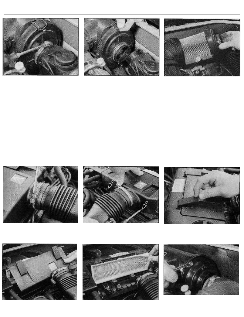
Every 18 000 miles
26.7 On 1580 cc models, slacken the
retaining clip and disconnect the air
temperature control valve . . .
to the duct, and secure them in position with
the retaining clips (where fitted).
1580 cc models
7 Slacken the retaining clip, and disengage
the air temperature control valve from the air
cleaner housing (see illustration).
8 Release the retaining clips, then remove the
cover from the side of the air cleaner housing.
Withdraw the filter element, noting which way
round it is fitted (see illustrations).
9 Install the new filter element in the housing,
ensuring that it is fitted the correct way round.
Refit the cover, securing it in position with the
retaining clips.
26.8a . . . then release the retaining
c l i p s . . .
10 Reconnect the air temperature valve to
the filter housing, and securely tighten its
retaining clip.
1761 cc and 1998 cc 8-valve
models
11 Slacken the retaining clip, and disconnect
the intake duct from the front of the cylinder
head cover (see illustration).
12 Slacken and remove the two retaining
screws situated at the front of the cylinder
head cover, then release the two air filter
cover retaining clips. Remove the filter cover
from the cylinder head cover, and withdraw
the filter element (see illustrations).
26.8b . . . and remove the cover and filter
element
13 Fit the new element in position in the
cylinder head cover. Refit the filter cover,
securing it in position with its retaining screws
and clips.
14 Reconnect the intake duct to the cylinder
head cover, and securely tighten its retaining
clip.
1905 cc models
15 Slacken the retaining clip, and disconnect
the intake duct from the end of the air cleaner
housing.
16 Slacken and remove the two retaining
nuts, then remove the cover from the end of
the filter housing. Withdraw the filter element,
26.11 On 1761 cc and 1998 cc 8-valve
models, disconnect the intake duct from
the front of the cylinder head cover . . .
26.12a . . . then slacken the retaining
screws (arrowed)...
26.12b . . . and release the retaining clips
26.12c Lift off the filter cover . . .
26.12d . . . and withdraw the filter element
26.16a On 1905 cc models, disconnect the
intake duct and undo the retaining nuts,
remove the end cover . . .
1•21
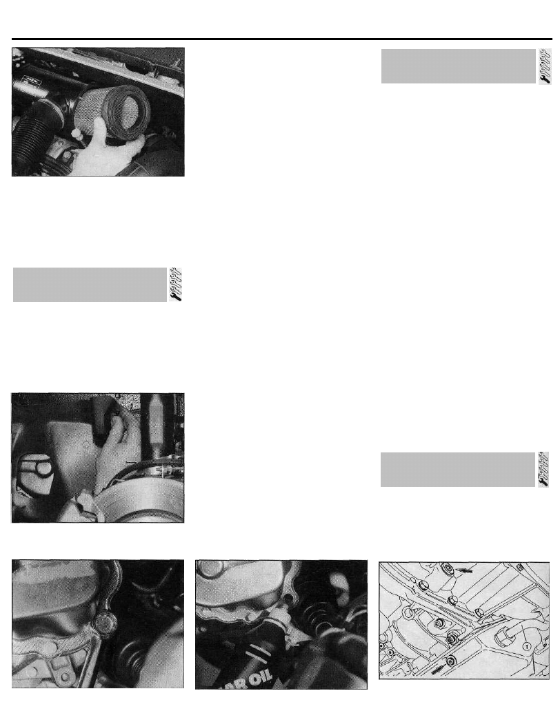
Every 24 000 miles
26.16b . . . and withdraw the filter element
noting which way round it is fitted (see
illustrations).
17 Install the new filter element in the
housing, ensuring that it is fitted the correct
way round. Refit the housing end cover, and
securely tighten its retaining nuts.
18 Reconnect the intake duct to the filter
housing, and securely tighten its retaining clip.
1998 cc 16-valve models
19 Firmly apply the handbrake, then jack up
the front of the vehicle and support it on axle
stands.
20 Working from underneath the vehicle,
release the retaining clips and remove the filter
housing cover, then lower out the filter element.
21 Install the new element in the filter
housing, and refit the housing cover. Secure
the cover in position with the retaining clips,
then lower the vehicle to the ground.
Every 24 000 miles or 2 years
28 Manual transmission oil
level check
Note: A new sealing washer will be required
for the transmission filler/level plug, when
refitting.
1 Park the car on a level surface. Check the oil
level before the car is driven, or wait at least 5
minutes after the engine has been switched off. If
the oil level is checked immediately after driving
the car, some of the oil will remain distributed
28.2 Removing the access cover from the
left-hand wheel arch liner
around the transmission components, resulting
in an inaccurate level reading.
2 Prise out the three retaining clips, and
remove the small access cover from the left-
hand wheel arch liner (see illustration).
3 Wipe clean the area around the filler/level
plug, which is the largest bolt among those
securing the end cover to the transmission.
Unscrew the plug and clean it; discard the
sealing washer (see illustration).
4 The oil level should reach the lower edge of
the filler/level hole. A certain amount of oil will
have gathered behind the filler/level plug, and
will trickle out when it is removed; this does
not necessarily indicate that the level is
correct. To ensure that a true level is
established, wait until the initial trickle has
stopped, then add oil as necessary until a
trickle of new oil can be seen emerging. The
level will be correct when the flow ceases; use
only good-quality oil of the specified type.
5 Refilling the transmission is an awkward
operation; above all, allow plenty of time for
the oil level to settle properly before checking
it. If a large amount had to be added to the
transmission, or if a large amount flowed out
on checking the level, refit the filler/level plug
and take the vehicle on a short journey. With
the new oil distributed fully around the
1 Work around the vehicle, and lubricate the
hinges of the bonnet, doors and tailgate with a
light machine oil.
2 Lightly lubricate the bonnet release
mechanism and exposed section of inner
cable with a smear of grease.
3 Check carefully the security and operation
of all hinges, latches and locks, adjusting
them where required. Check the operation of
the central locking system (if fitted).
4 Check the condition and operation of the
tailgate struts, renewing them if either is
leaking or is no longer able to support the
tailgate securely when raised.
transmission components, recheck the level
after allowing time for it to settle again (see
illustration).
6 If the transmission has been overfilled so
that oil flows out as soon as the filler/level
plug is removed, first check that the car is
completely level (front-to-rear and side-to-
side). Allow any surplus oil to drain off into a
suitable container.
7 When the level is correct, fit a new sealing
washer to the filler/level plug. Tighten the plug
to the specified torque wrench setting. Wash
off any spilt oil. Refit the access cover to the
wheel arch liner, and secure it in position with
its retaining clips.
8 Frequent need for topping-up indicates a
leak, which should be found and corrected
before it becomes serious.
29 Automatic transmission fluid
renewal
1 Take the vehicle on a short run, to warm the
transmission up to normal operating
temperature.
2 Park the car on level ground, then switch off
the ignition and apply the handbrake firmly.
For improved access, jack up the front of the
28.3 Removing the manual transmission
filler/level plug (1905 cc model shown)
28.5 Topping-up the manual
transmission oil
29.3 Automatic transmission fluid drain
plugs (arrowed). Transmission is refilled
via the dipstick tube (1)
1•22
27 Hinge and lock lubrication
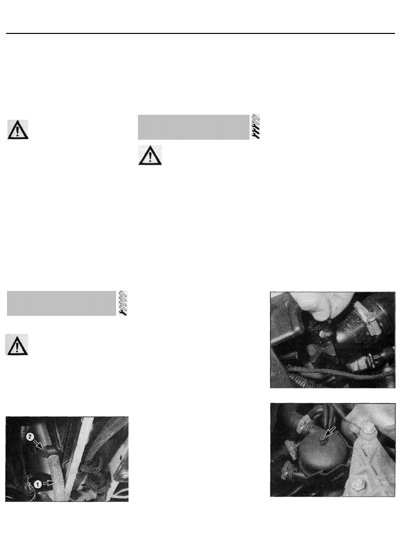
Every 40 000 miles
car and support it securely on axle stands.
Note that, when refilling and checking the fluid
level, the car must be lowered to the ground,
and level, to ensure accuracy.
3 Remove the dipstick, then position a
suitable container under the transmission. The
transmission has two drain plugs: one on the
sump, and another on the bottom of the
differential housing (see illustration).
4 Unscrew both drain plugs, and allow the
fluid to drain completely into the container.
Warning: If the fluid is hot, take
precautions against scalding.
Clean the drain plugs, being
especially careful to wipe any metallic
particles off the magnetic insert. Discard
the original sealing washers; these should
be renewed whenever they are disturbed.
5 When the fluid has finished draining, clean
the drain plug threads and those of the
transmission casing. Fit a new sealing washer
to each drain plug, and refit the plugs to the
transmission, tightening each securely. If the
car was raised for the draining operation, now
lower it to the ground. Make sure that the car
is level (front-to-rear and side-to-side).
6 Refilling the transmission is an awkward
operation, adding the specified type of fluid to
the transmission a little at a time via the dipstick
tube. Use a funnel with a fine mesh gauze, to
avoid spillage, and to ensure that no foreign
matter enters the transmission. Allow plenty of
time for the fluid level to settle properly.
7 Once the level is up to the MAX mark on the
dipstick, refit the dipstick. Start the engine,
and allow it to idle for a few minutes. Switch
the engine off, then recheck the level,
topping-up if necessary. Take the car on a
short run to fully distribute the new fluid
around the transmission, then recheck the
fluid level as described in Section 10.
30 Brake fluid renewal
Warning: Brake hydraulic fluid
can harm your eyes, and will
damage painted surfaces, so use
extreme caution when handling and
pouring it. It is also poisonous and highly-
inflammable. Do not use fluid that has
been standing open for some time, as it
absorbs moisture from the air. Excess
moisture in the fluid can cause a
dangerous loss of braking effectiveness.
1 The procedure is similar to that for bleeding
the hydraulic system, described in Chapter 9.
Allowance should be made for all the old fluid
to be expelled when bleeding a section of the
circuit. The brake fluid reservoir should be
emptied by syphoning, using a clean poultry
Every 40 000 miles or 2 years
Cooling system draining
Warning: Wait until the engine is
cold before starting this
procedure. Do not allow antifreeze
to come in contact with your skin, or with
the painted surfaces of the vehicle. Rinse
off spills immediately with plenty of water.
Never leave antifreeze lying around in an
open container, or in a puddle in the
driveway or on the garage floor. Children
and pets are attracted by its sweet smell,
but antifreeze can be fatal if ingested.
31.2 Tubing (1) attached to radiator
coolant drain outlet. Note drain plug (2)
1 To drain the cooling system, remove the
expansion tank filler cap. Turn the cap anti-
clockwise until it reaches the first stop. Wait
until any pressure remaining in the system is
released, then push the cap down, turn it anti-
clockwise to the second stop, and lift off.
2 Position a suitable container beneath the
coolant drain outlet at the lower left-hand side
of the radiator. If desired, a suitable length of
tubing can be attached to the outlet, to direct
the flow of coolant (see illustration).
3 Loosen the drain plug (there is no need to
remove it completely), and allow the coolant
to drain into the container.
4 To assist draining, open the cooling system
bleed screws, which are located as follows:
1124 cc and 1360 cc models
(a) At the top left-hand corner of the radiator
(see illustration).
(b) In the top of the coolant outlet housing
mounted on the left-hand end of the
cylinder head.
(c) In the heater outlet hose connection (to
improve access, this bleed screw may be
located in the end of an extension hose
joined to the connection).
(d) In the top of the cooling system de-
aeration chamber mounted on the right-
hand rear corner of the cylinder block -
pre-1993 models without air conditioning
(see illustration).
baster or similar, before starting. Take care not
to spill fluid onto the surrounding paintwork.
2 Fill the brake fluid reservoir with fresh fluid.
Working as described in Chapter 9, open the
first bleed nipple in the sequence, and pump
the brake pedal gently until the fluid level
approaches the "MIN" mark. Do not allow the
fluid in the reservoir to fall below this level.
3 Top-up the reservoir to the "MAX" level with
new fluid, and continue pumping until new
fluid can be seen emerging from the bleed
nipple. Old hydraulic fluid is invariably much
darker in colour than the new, making it easy
to distinguish the two. Tighten the nipple, and
top the reservoir level up to the "MAX" level.
4 Work through all the remaining nipples in
the sequence, until new fluid can be seen at all
of them. Be careful to keep the master cylinder
reservoir topped-up to above the "MIN" level
at all times, or air may enter the system and
greatly increase the length of the task.
5 When the operation is complete, check that
all nipples are securely tightened, and that
their dust caps are refitted. Wash off all traces
of spilt fluid, and recheck the master cylinder
reservoir fluid level.
6 Check the operation of the brakes before
taking the car on the road. In particular, check
for any "sponginess" felt through the pedal; this
would indicate that air has been allowed to enter
the system, necessitating further bleeding.
31.4a Removing the radiator bleed screw
31.4b Cooling system de-aeration chamber
bleed screw (arrowed) - pre-1993 1124 cc
and 1360 cc models without air conditioning
1•23
31 Coolant renewal

Engine
Valve clearances -1124 cc and 1360 cc models:
Inlet 0.20 mm
Exhaust 0.40 mm
Oil filter (all models) Champion F104
Cooling system
Antifreeze mixture:
28% antifreeze Protection down to -15°C (5°F)
50% antifreeze Protection down to -30°C (-22°F)
Note: Refer to antifreeze manufacturer for latest recommendations.
Fuel system
Idle speed (all models) 850 ± 50 rpm
Idle mixture CO content:
Carburettor models 0.8 to 1.2 %
Fuel injection models:
Without a catalytic converter 1 to 2 %
With a catalytic converter Less than 1.0 %
Air filter element:
1124 cc, 1360 cc and 1580 cc models Champion V401
Other models Champion type not available
Fuel filter:
Carburettor models Champion L101
Fuel injection models Champion L201
Ignition system
Ignition timing Refer to Chapter 5
Spark plugs:
1905 cc (D6E engine) models and1998 cc 16-valve models Champion RC7YCC
All other models Champion RC9YCC
Spark plug electrode gap* 0.8 mm
Ignition HT lead resistance Approximately 600 ohms per 100 mm length
*The spark plug gap quoted is that recommended by Champion for their specified plugs listed above. If spark plugs of any other type are to be
fitted, refer to their manufacturer's spark plug gap recommendations.
Brakes
Brake pad friction material minimum thickness (front and rear) 2.0 mm
Brake shoe friction material minimum thickness 1.5 mm
Tyres
Tyre size 165/70 R 13,175/65 R 14, 185/60 R 14 or 195/55 R 15 (depending
on model)
Pressures - (tyres cold): Front Rear
165/70 R 13 tyres 2.2 bar (32 psi) 2.2 bar (32 psi)
175/65 R 14 tyres 2.1 bar (30 psi) 2.1 bar (30 psi)
185/60 R 14 tyres* 2.2 bar (32 psi) 2.2 bar (32 psi)
195/55 R 15 tyres* 2.2 bar (32 psi) 2.3 bar (33 psi)
Note: Pressures apply only to original-equipment tyres, and may vary if any other make or type is fitted; check with the tyre manufacturer or
supplier for correct pressures if necessary.
* Models with these tyres have a "space-saver" spare wheel, fitted with a smaller tyre. The smaller spare tyre should run at 2.4 bars (35 psi). Note
that the vehicle should not be driven at speeds exceeding 100 mph (160 km/h) whilst the "space-saver" spare wheel is fitted.
Wiper blades
Front Champion X-5503
Rear Champion X-4503
Torque wrench settings Nm ibf ft
Rocker arm adjusting screw locknut -1124 cc and 1360 cc models . . . 18 13
Spark plugs 25 18
Manual transmission:
1124 cc and 1360 cc models:
Filler/level and drain plugs 25 18
1580 cc and larger-engined models:
Filler/level plug 22 16
Drain plug 35 26
1•24
Specifications
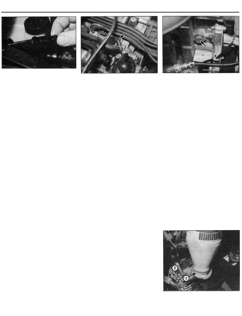
Every 40 000 miles
31.4c Removing the heater outlet hose
bleed screw (screw located in extension
hose)
1580 cc and larger-engined models
(a) At the top left-hand corner of the radiator.
(b) In the top of the thermostat housing
cover.
(c) In the heater outlet hose connection (to
improve access, this bleed screw may be
located in the end of an extension hose
joined to the connection) (see
illustration).
(d) In the coolant hose located directly above
the thermostat housing cover - all except
1998 cc 16-valve models (see
illustration).
(e) One on the front coolant hose
connection, and one on the rear coolant
hose connection to the coolant outlet
housing mounted on the left-hand end of
the cylinder head - 1998 cc 16-valve
models.
5 When the flow of coolant stops, reposition
the container below the cylinder block drain
plug. On 1998 cc models, the drain plug is
located at the rear of the cylinder block; on all
other models, the plug is located on the front
of the block.
6 Remove the drain plug, and allow the
coolant to drain into the container (see
illustration).
7 If the coolant has been drained for a reason
other than for renewal, then provided it is
clean and less than two years old, it can be
re-used.
Cooling system flushing
Note: A new sealing ring will be required when
refitting the radiator bottom hose.
8 If coolant renewal has been neglected, or if
the antifreeze mixture has become diluted,
then in time, the cooling system may gradually
lose efficiency. The coolant passages will
eventually become restricted due to rust,
scale deposits, and other sediment. This
situation can be remedied by flushing the
system clean.
9 The radiator should be flushed
independently of the engine, to avoid
unnecessary contamination.
Radiator flushing
10 To flush the radiator, first tighten the
radiator drain plug and the radiator bleed
screw.
31.4d Thermostat housing coolant hose
bleed screw (arrowed) -1580 cc model
11 Disconnect the top and bottom hoses
from the radiator (it is only necessary to
disconnect the larger radiator bottom hose),
as described in Chapter 3, Section 2.
12 Insert a garden hose into the radiator top
inlet. Direct a flow of clean water through the
radiator, and continue flushing until clean
water emerges from the radiator bottom
outlet.
13 If, after a reasonable period, the water still
does not run clear, the radiator can be flushed
with a good proprietary cleaning agent. It is
important that the cleaning agent
manufacturer's instructions are followed
carefully. If the contamination is particularly
bad, insert the hose in the radiator bottom
outlet, and flush the radiator in the reverse
direction to normal flow.
Engine flushing
14 To flush the engine, first refit the cylinder
block drain plug, and tighten the cooling
system bleed screws.
15 Remove the thermostat as described in
Chapter 3, then temporarily refit the
thermostat cover.
16 With the top and bottom hoses
disconnected from the radiator, insert a
garden hose into the radiator top hose. Direct
a clean flow of water through the engine, and
continue flushing until clean water emerges
from the radiator bottom hose.
17 On completion of flushing, refit the
thermostat and reconnect the hoses with
reference to Chapter 3. Note that a new
sealing ring should be used when
reconnecting the radiator bottom hose.
Cooling system filling
18 Before attempting to fill the cooling
system, make sure that all hoses and clips are
in good condition, and that the clips are tight.
Note that antifreeze must be used all year
round, to prevent corrosion of the engine
components (refer to the following sub-
Section). Also check that the radiator and
cylinder block drain plugs are in place and
tight.
19 Remove the expansion tank filler cap.
20 Open all the cooling system bleed screws
(see paragraph 4).
21 Some of the cooling system hoses are
31.6 Cylinder block drain plug (arrowed) -
1124 cc and 1360 cc models
positioned at a higher level than the top of the
radiator expansion tank. It is therefore necessary
to use a "header tank" when refilling the cooling
system, to reduce the possibility of air being
trapped in the upper parts of the system.
Although Citroen dealers use a special header
tank, the same effect can be achieved by using
a suitable bottle, with a seal, between the bottle
and the expansion tank (see illustration).
22 Clamp the expansion tank breather hose,
then fit the "header tank" to the expansion
tank, and slowly fill the system. Coolant will
emerge from each of the bleed screws in turn,
starting with the lowest screw. As soon as
coolant free from air bubbles emerges from
the lowest screw, tighten that screw, and
watch the next bleed screw in the system.
Repeat the procedure until the coolant is
emerging from the highest bleed screw in the
cooling system, then tighten all bleed screws
securely.
23 Start the engine, and run it at a fast idle
speed (do not exceed 2000 rpm) until the
cooling fans cut in.
24 Remove the "header tank", taking great
care not to scald yourself with the hot coolant,
then fit the expansion tank cap. Unclamp the
expansion tank breather hose.
25 Stop the engine, and allow it to cool.
26 Check the coolant level, which should be
up to the "MAX" mark on the side of the
expansion tank. Top-up the level if necessary.
31.21 A "header tank" arrangement will be
required to refill the cooling system. Note
the O-ring seal (1) and the clamped
breather hose (2)
1•25
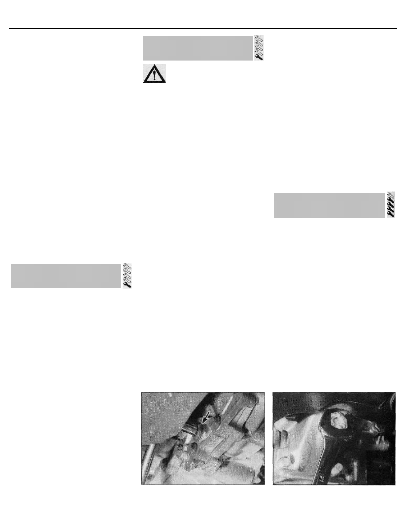
Every 72 000 miles
Antifreeze mixture
27 The antifreeze should always be renewed
at the specified intervals. This is necessary
not only to maintain the antifreeze properties,
but also to prevent corrosion which would
otherwise occur as the corrosion inhibitors
become progressively less effective.
28 Always use an ethylene-glycol-based
antifreeze which is suitable for use in mixed-
metal cooling systems. The quantity of
antifreeze required, and the levels of
protection, are indicated in the Specifications.
29 Before adding antifreeze, the system
should be drained, preferably flushed, and all
hoses checked for condition and security.
30 After filling with antifreeze, a label should
be attached to the expansion tank, stating the
type and concentration of antifreeze used,
and the date installed. Any subsequent
topping-up should be made with the same
type and concentration of antifreeze.
31 Do not use engine antifreeze in the
windscreen/tailgate washer system, as it will
cause damage to the vehicle paintwork. A
screenwash additive should be added to the
washer system in its manufacturer's
recommended quantities.
Warning: Before carrying out the
following operation, refer to the
precautions given in "Safety
first!" at the beginning of this manual, and
follow them implicitly. Petrol is a highly-
dangerous and volatile liquid, and the
precautions necessary when handling it
cannot be overstressed.
1 The fuel filter is situated underneath the rear
of the vehicle, mounted on the right-hand side
of the fuel tank. To gain access to the filter,
chock the front wheels, then jack up the rear
of the vehicle and support it on axle stands.
2 Clamp the fuel hose on the tank side of the
filter. Bearing in mind the information given in
the relevant Part of Chapter 4.8 on
depressurising the fuel system, release the
retaining clips and disconnect the fuel hoses
from the filter. Be prepared for fuel spillage.
3 Note the direction of the arrow marked on
the filter body. Slacken the retaining clamp
screw, then slide the filter out of the clamp,
and remove it from underneath the vehicle.
Every 72 000 miles
34 Manual transmission oil
renewal
Note: New sealing washers will be required
for the transmission filler/level and drain plugs,
when refitting.
1 This operation is much quicker and more
efficient if the car is first taken on a journey of
sufficient length to warm the engine and
transmission up to normal operating
temperature.
2 Park the car on level ground, then switch off
the ignition and apply the handbrake firmly.
For improved access, jack up the front of the
car and support it securely on axle stands.
Note that, when refilling and checking the oil
level, the car must be lowered to the ground,
and level, to ensure accuracy.
3 Prise out the three retaining clips, and
remove the small access cover from the left-
hand wheel arch liner.
4 Wipe clean the area around the filler/level
plug, which is the largest bolt among those
securing the end cover to the transmission.
Unscrew the filler/level plug, and remove it
from the transmission.
5 Position a suitable container under the drain
plug (situated at the rear of the transmission)
and unscrew the plug. On 1124 cc and 1360 cc
models, the plug is on the left-hand side of the
differential housing; on 1580 cc and larger-
engined models, it is on the base of the
differential housing. A square-section wrench
(the same as that used for the engine sump
drain plug) may be required to undo the drain
plug on some models (see illustrations).
6 Allow the oil to drain completely into the
container. If the oil is hot, take precautions
against scalding. Clean both the filler/level
and the drain plugs, being especially careful
to wipe any metallic particles off the magnetic
inserts. Discard the original sealing washers;
they should be renewed whenever they are
disturbed.
7 When the oil has finished draining, clean
the drain plug threads and those of the
transmission casing. Fit a new sealing washer,
and refit the drain plug, tightening it to the
specified torque wrench setting. If the car was
raised for the draining operation, now lower it
to the ground. Make sure that the car is level,
4 Dispose safely of the old filter; it will be
highly-inflammable, and may explode if
thrown on a fire.
5 Slide the new filter into position in the
clamp, ensuring that the arrow on the filter
body is pointing in the direction of the fuel
flow, ie. towards the throttle body/fuel rail.
This can be determined by tracing the fuel
hoses back along their length.
6 Connect the fuel hoses to the filter, and
secure them in position with their retaining
clips. Remove the hose clamp.
7 Start the engine, and check the filter hose
connections for leaks. Lower the vehicle to
the ground on completion.
Every
48 000 miles
Refer to the relevant Part of Chapter 2.
both front-to-rear and side-to-side.
8 Refilling the transmission is an awkward
operation. Above all, allow plenty of time for
the oil level to settle properly before checking
it.
9 Refill the transmission with the exact
amount of the specified type of oil, then check
the oil level as described in Section 28. If the
correct amount was poured into the trans-
mission, and a large amount flows out on
checking the level, refit the filler/level plug and
take the car on a short journey. With the new
oil distributed fully around the transmission
components, recheck the level after allowing
time for it to settle again.
10 Once the level is correct, refit the access
cover to the wheel arch liner, securing it in
position with its retaining clips.
34.5a Removing the manual transmission
drain plug (arrowed) - 1124 cc and 1360 cc
models
34.5b Removing the manual transmission
drain plug - 1580 cc and larger-engined
models
1•26
32 Fuei filter renewal -
fuel injection models
33 Timing belt renewal
Wyszukiwarka
Podobne podstrony:
TD 01
Ubytki,niepr,poch poł(16 01 2008)
01 E CELE PODSTAWYid 3061 ppt
01 Podstawy i technika
01 Pomoc i wsparcie rodziny patologicznej polski system pomocy ofiarom przemocy w rodzinieid 2637 p
zapotrzebowanie ustroju na skladniki odzywcze 12 01 2009 kurs dla pielegniarek (2)
01 Badania neurologicz 1id 2599 ppt
01 AiPP Wstep
ANALIZA 01
01 WPROWADZENIA
01 piątek
choroby trzustki i watroby 2008 2009 (01 12 2008)
syst tr 1 (2)TM 01 03)13
Analiza 01
więcej podobnych podstron