1
INTRODUCTION
GENERAL
This section has the description and repair procedures
for the oil clutch assembly and the manual transmission.
DESCRIPTION
Oil Clutch Assembly, H6.00–7.00XL
(H135–155XL) (See FIGURE 1.)
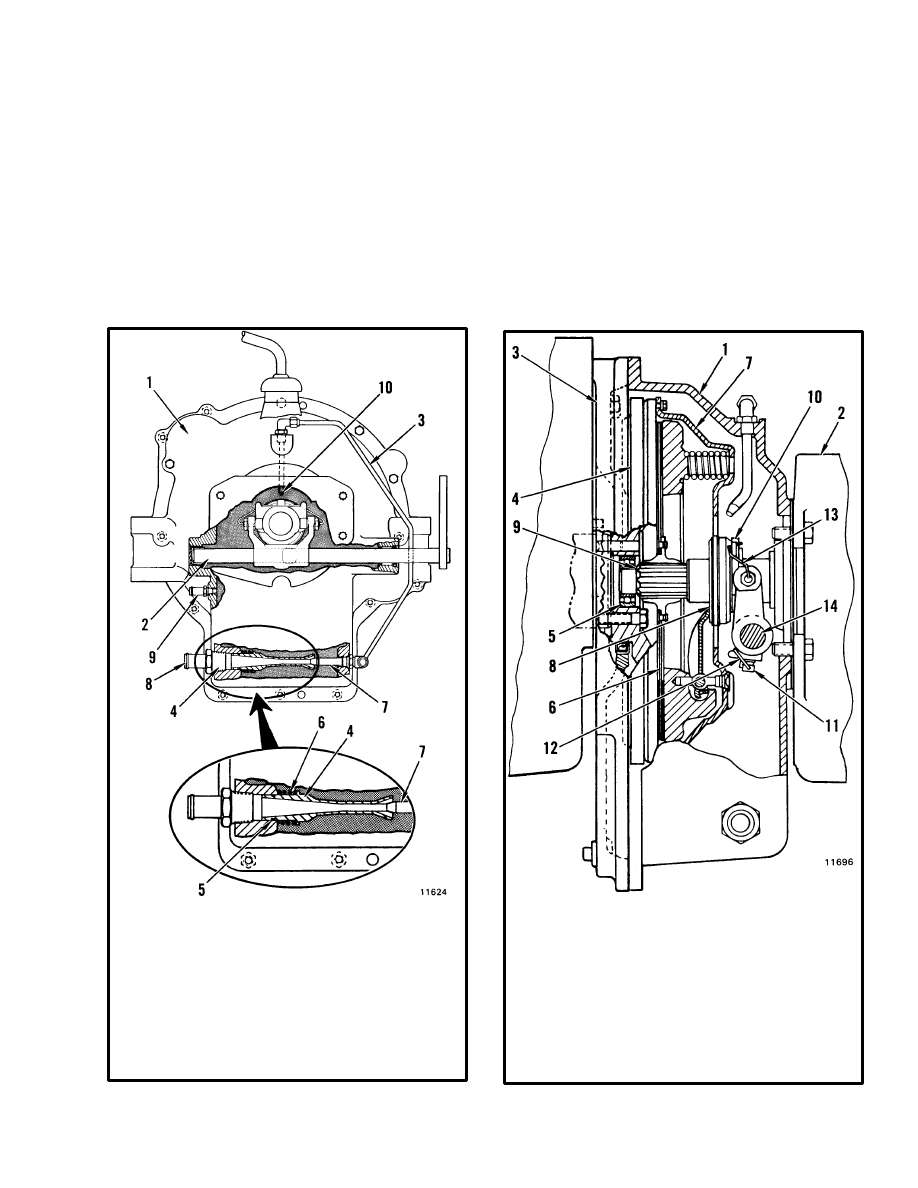
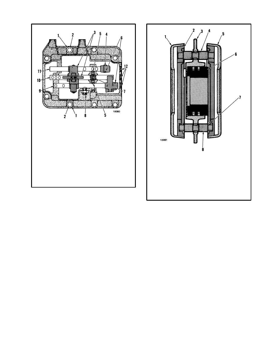
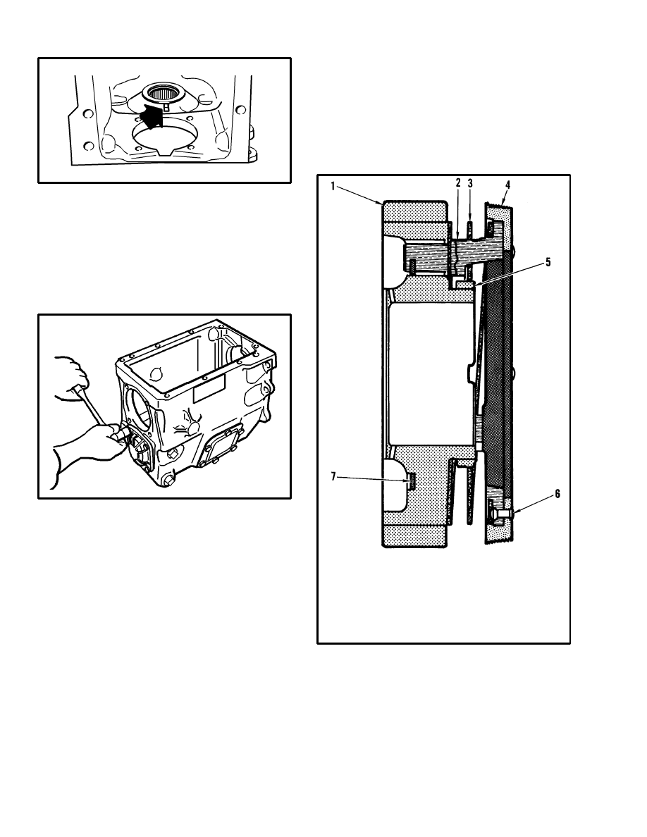
FIGURE 1. OIL CLUTCH ASSEMBLY
1. CLUTCH HOUSING
2. RELEASE SHAFT
3. OIL SUPPLY TUBE
4. JET PUMP
5. O–RING
6. SPRING
7. JET PUMP NOZZLE
8. RETURN LINE
9. BREATHER LINE
10. NOZZLE FOR COOLING OIL
The function of the clutch is to connect and disconnect
the power from the engine to the transmission. The
clutch disc has splines and slides on the splines of the
transmission input shaft. The pressure plate cover is fas-
tened to the engine flywheel by capscrews. There are
coil springs between the cover and the pressure plate.
When the pressure plate pushes the clutch disc against
the flywheel, the clutch disc must turn with the fly-
wheel.
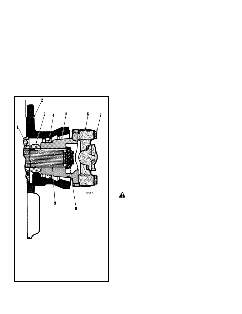
FIGURE 2. OIL CLUTCH
1. CLUTCH HOUSING
2. TRANSMISSION
HOUSING
3. ENGINE ADAPTER
4. FLYWHEEL
5. PILOT BEARING
6. CLUTCH DISC
7. PRESSURE PLATE
8. RELEASE BEARING
9. INPUT SHAFT FOR
TRANSMISSION
10. YOKE
11. LOCK SCREW
12. LOCKWIRE
13. SPRING
14. RELEASE SHAFT
2
When the clutch pedal is depressed, the release bearing
pushes against the four levers in the pressure plate.
These levers pull the pressure plate toward the cover, re-
leasing the tension of the pressure plate on the friction
disc.
The clutch is also used for inching. When inching, the
release mechanism does not fully release the force of the
pressure plate on the clutch disc. The disc turns at a dif-
ferent speed than the flywheel. Because the pressure
plate and flywheel are touching the disc, the parts get
hot. The oil supply tube sends hydraulic oil to the clutch
parts for cooling.
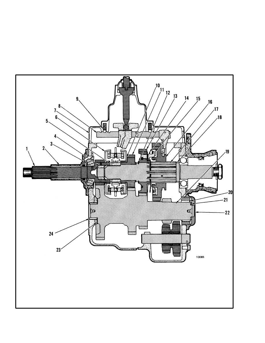
FIGURE 3. MANUAL TRANSMISSION
1. INPUT SHAFT
2. BEARING RETAINER
3. TAPERED ROLLER BEARING
4. ROLLER BEARING
5. THRUST BEARING
6. SYNCHRONIZER ASSEMBLY
7. TOP COVER
8. RAIL
17. MAINSHAFT
18. SPACER
19. CLUSTER GEAR
20. NEEDLE BEARING
21. THRUST BEARING AND RACE
22. BEARING RETAINER
23. THRUST WASHER
24. NEEDLE BEARING
9. DETENT BALL AND SPRING
10. SHIM
11. THIRD GEAR
12. SPECIAL SNAP RING
13. SECOND GEAR
14. SPRING
15. SYNCHRONIZER RING
16. FIRST GEAR

3
The oil supply for the clutch assembly comes from the
return circuit of the steering system. From the steering
control unit, the oil flows to the brake valve and then the
clutch housing. At the clutch housing the oil goes to two
fittings. One fitting supplies oil for cooling the clutch
disc. The other fitting supplies the oil to operate the jet
pump at the bottom of the clutch housing. The jet pump
removes the cooling oil from the clutch housing and
sends it back to the hydraulic tank. A hose fitting near
the center of the housing is used as a breather for the
clutch housing.
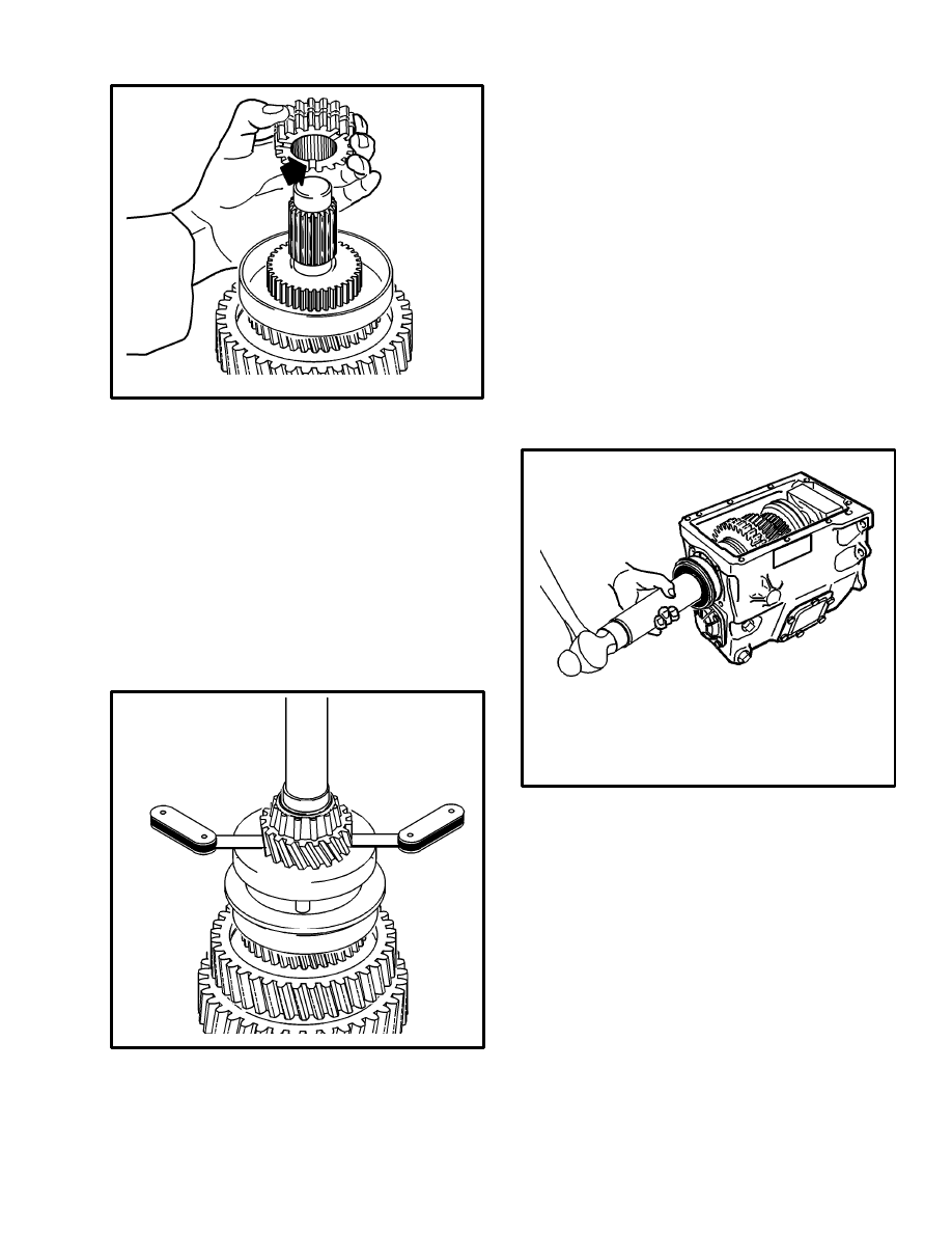
Manual Transmission (See FIGURE 3.)
The manual transmission has four speeds. The For-
ward–Reverse arrangement is in the speed reducer. A
spacer in the reverse lug and a setscrew in the rail pre-
vents the use of the reverse gear that is in the transmis-
sion.
The manual transmission has an input shaft, a mainshaft
and a cluster gear. The second, third and fourth speed
gears have synchronizers and are always engaged with
the cluster gear. The first speed gear slides on the main-
shaft and engages the cluster gear only when first gear is
selected.
The input shaft has a tapered roller bearing as a support.
The mainshaft has a ball bearing. The end of the main-
shaft rotates inside a bore in the input shaft gear. A roller
bearing and thrust bearing separate the two shafts. The
cluster gear has a needle bearing on each end of the gear.
A thrust bearing in the cluster retainer and a thrust wash-
er on the case keep the cluster gear in position.
The synchronizer assemblies make the gears turn the
same speed as the main shaft during a gear change.
When the clutch pedal is pushed, the input shaft and the
gears turn freely. During a gear change the selector fork
moves the sliding sleeve toward the gear. The gear and
the mainshaft are not turning at the same speed. When
the sliding sleeve moves toward the gear, it pushes on
the shoulders of the pins of the synchronizer ring. The
synchronizer ring causes friction on the stop ring that is
fastened to the gear. The friction causes the gear to turn
the same speed as the sliding sleeve. The sliding sleeve
can rotate the synchronizer ring a small amount when
the mainshaft and the gear are turning the same speed.
The sliding sleeve can now slide past the shoulder of the
pins. The splines of the sliding sleeve engage both the
splines of the gear and the splines of the mainshaft. The
gear must now turn with the mainshaft. The synchroniz-
ers prevent wear on the splines by making sure the parts
are turning the same speed when the splines are being
engaged.
A gear selector lever on the transmission cover moves
the two rails. One of the rails moves the first and second
speed fork. The other rail moves the third and fourth
speed fork. An interlock plunger prevents both rails
from moving at the same time. Detent balls and springs
keep the rails and forks in the correct position. The third
rail is not used and is prevented from moving by a plug
in the transmission cover.
REPAIRS
OIL CLUTCH ASSEMBLY
Removal and Disassembly (See FIGURE 1.
and FIGURE 2.)
1. Remove the transmission and clutch housing as de-
scribed in the procedures for the transmission.
2. Remove the pressure plate assembly and clutch disc
from the flywheel.
3. Remove the clutch linkage parts from the clutch hous-
ing as necessary.
Cleaning
Clean all parts of the clutch with solvent. The two clutch
shaft bearings must be free of oil when inspected for
wear. Do not try to clean the clutch release bearing.
Inspection
1. Inspect the clutch disc for holes in the lining. Check
for burnt lining that is black or hard. Check for loose riv-
ets or a bent plate. Check the splines on the disc for wear
or damage.
2. Inspect the pressure plate for grooves or burned areas.
Look for cracks on the surface of the pressure plate.
Check for broken springs. Inspect the pressure plate
4
cover for cracks near the fulcrums for the levers. Check
the levers for wear or damage.
3. Inspect the splines of the input shaft for wear or dam-
age. Inspect the bearings for wear on the races and balls.
The cam bearings must turn freely.
4. Inspect the shaft for the clutch release bearing. In-
spect the needle bearings for wear.
5. The release bearing must turn freely. Check the sur-
face for grooves or wear.
6. Inspect the flywheel for grooves and cracks that are
longer than 6.25 mm (0.25 in). Look for areas that have
been too hot and have turned blue.
Assembly and Installation (See FIGURE 1.
and FIGURE 2.)
1. Install the pilot bearing in the flywheel.
2. Hold the correct side of the clutch disc (rivet heads to-
ward the transmission) against the flywheel. Put the
pressure plate against the flywheel and disc. Start sever-
al capscrews through the holes in the pressure plate cov-
er. Do not tighten the capscrews.
3. Slide the input shaft through the splines of the clutch
disc into the pilot bearing. Tighten the capscrews for the
pressure plate cover to 20 N.m (15 lbf ft). Remove the
input shaft.
4. If removed, install the flywheel housing to the trans-
mission housing. Use a gasket between the housings.
Tighten the capscrews at the transmission housing to
110 N.m (80 lbf ft).
5. If worn, replace the needle bearings in the clutch
housing. Replace the oil seal for the release shaft. Install
the release shaft in the clutch housing. Install the yoke,
lock screw and lock wire. Install the release bearing and
spring on the yoke.
6. Install the jet pump with O–ring and spring in the
clutch housing. Install the jet pump nozzle in the clutch
housing. Tighten the fitting for the nozzle, making sure
the nozzle holds the jet pump in position.
7. Install the tube and nozzle for the cooling oil. Make
sure the nozzle for the cooling oil is toward the holes in
the pressure plate.
8. Install the clutch housing on the engine adapter. Use a
sealant (Hyster Part No. 264159) on the flange of the
clutch housing. Tighten the capscrews to 31 N.m (23 lbf
ft).
9. Install the drive shaft. Use a thread locking compound
and tighten the capscrews for the universal joints to 28
N.m (20 lbf ft).
10. Adjust the clutch pedal linkage as described in
Checks and Adjustments.
TRANSMISSION
Removal, H6.00–7.00XL (H135–155XL)
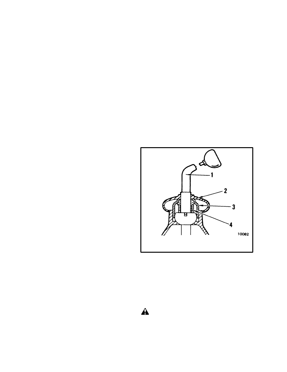
1. Remove the floorplates. Remove the rubber cover
from the transmission cover. Push on the cap for the se-
lector lever and rotate the cap until the spring pushes the
cap from the tower. See FIGURE 4. Remove the lever
assembly. Put a clean cloth in the socket for the lever.
FIGURE 4. LEVER ASSEMBLY
1. SELECTOR LEVER
2. RUBBER COVER
3. CAP
4. SPRING
2. Remove any clamps that are fastened to the transmis-
sion. Disconnect the oil lines at the clutch housing. Put
caps on the open lines.
3. Loosen the eyebolts for the clutch pedal springs. Re-
move the springs. Disconnect the clutch linkage at the
clutch housing.
WARNING
Always loosen the eyebolts for the clutch pedal
springs when working on the clutch.
4. Remove the four capscrews from the yoke at the uni-
versal joint. Separate the universal joint from the yoke.
5
Remove the drive shaft from the speed reducer. Put the
transmission in gear and loosen the mainshaft nut.
5. Put straps around the transmission and connect a lift-
ing device to the straps. Make sure the lifting device is
holding the weight of the transmission. Remove the
capscrews that hold the engine mounts to the frame. Re-
move the capscrews that hold the engine mounts to the
clutch housing. Remove the mounts.
6. Lower the transmission and engine a small amount
using the lifting device. Make sure no parts of the engine
touch the firewall. Put blocks under the engine adapter
to keep it in position.
7. Remove the capscrews that hold the clutch housing to
the engine adapter. Move the transmission from the en-
gine and lift the transmission from the lift truck.
8. Remove the four capscrews that hold the transmission
to the clutch housing. Separate the housings.
Disassembly
1. Remove the drain plug and drain the oil from the
transmission case.
2. Put the selector lever in the Neutral position. Remove
the capscrews from the transmission cover. Remove the
cover. Move the sliding sleeve into the Fourth Gear
position. Move the first speed gear into the Second Gear
position to prevent the mainshaft from turning. Remove
the nut for the output yoke. Remove the output yoke.
3. Remove the capscrews for the mainshaft bearing re-
tainer. Remove the mainshaft bearing retainer and main-
shaft spacer.
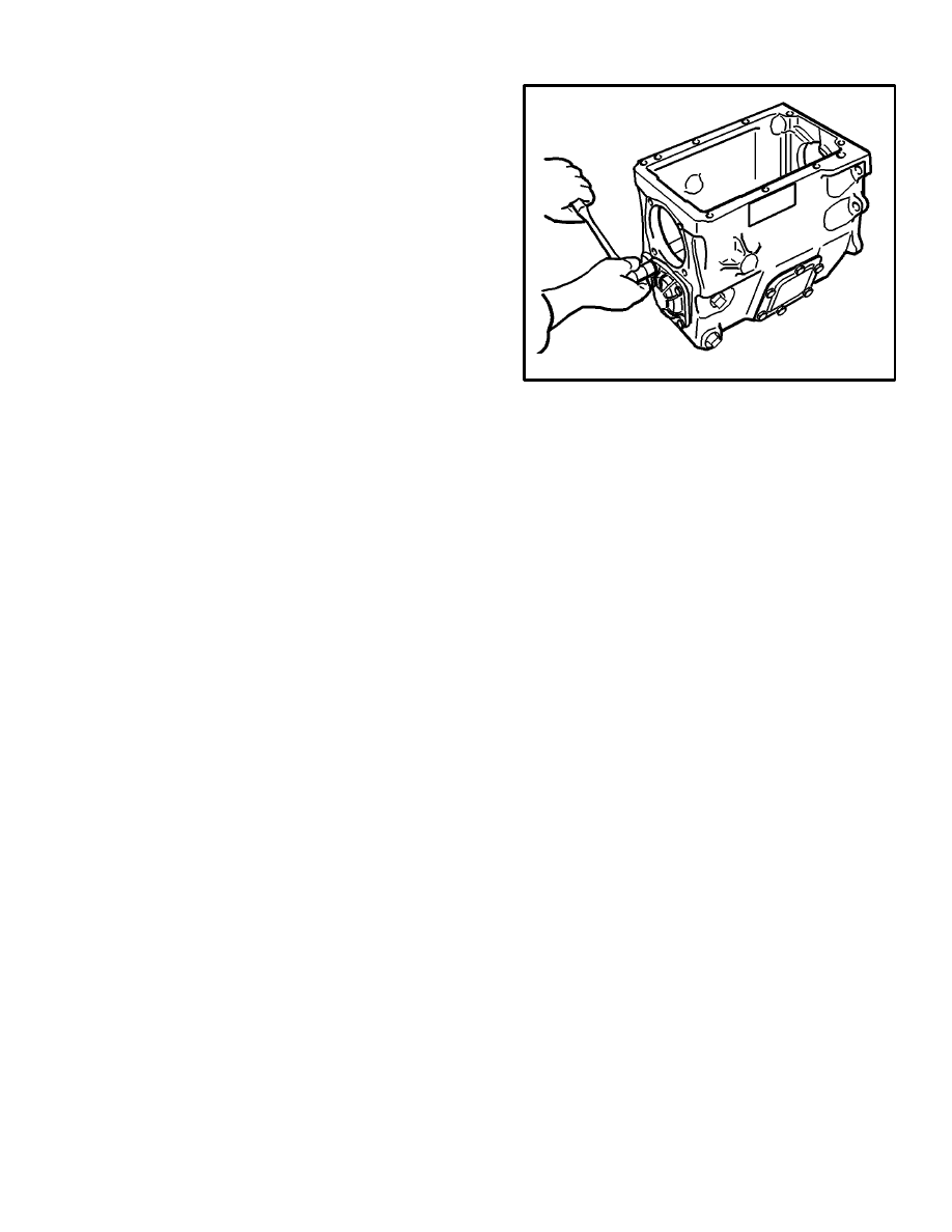
4. Remove the capscrews for the retainer for the cluster
gear bearing. See FIGURE 5. Remove the bearing re-
tainer, thrust race and thrust bearing.
5. Remove the capscrews from the bearing retainer for
the input shaft. Slide the bearing retainer from the input
shaft. Rotate the input shaft so that the notch in the
splines of the input shaft aligns with the teeth of the clus-
ter gear. Pull the input shaft from the transmission.
FIGURE 5. REMOVING THE
BEARING RETAINER
10086
6. Push the mainshaft toward the output end of the trans-
mission case until the bearing is out of the case. Use a
puller to remove the bearing from the mainshaft.
7. Remove the thrust bearing from the front of the main-
shaft. Slide the third and fourth speed synchronizer from
the mainshaft and remove it from the case.
8. Lift the mainshaft assembly from the transmission
case. Prevent the first speed gear from sliding on the
mainshaft.
9. Remove the capscrew and retainer from the reverse
idler shaft. Pull the idler shaft from the transmission
case. Remove the reverse idler gear from the transmis-
sion case.
10. Remove the capscrews from the bearing retainer for
the cluster gear. Lightly hit the bearing retainer with a
plastic hammer to loosen it from the case. Remove the
bearing retainer, thrust race and thrust bearing.
11. Remove the cluster gear from the case. Remove the
thrust washer. Remove the bearing for the cluster gear
by pushing it into the case.
12. If the tapered roller bearings needs to be replaced,
use a puller to remove the bearing cup from the bearing
retainer. See FIGURE 6.
6
FIGURE 6. REMOVING THE BEARING CUP
10093
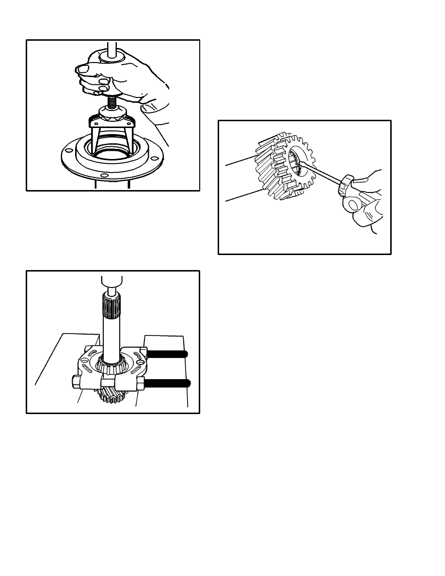
13. Remove the seal for the input shaft with a slide ham-
mer.
14. If necessary, remove the bearing cone from the input
shaft. Make sure the puller does not pull on the bearing
cage. See FIGURE 7.
FIGURE 7. REMOVING THE BEARING CONE
10091
15. Slide third gear from the mainshaft.
16. Slide the spacer and first gear from the mainshaft.
17. Use a screwdriver to lift one end of the special snap
ring. Remove both parts of the special snap ring from the
mainshaft. Slide second gear and the synchronizer from
the mainshaft. Remove the snap ring from the synchro-
nizer pins. Remove the synchronizer ring and spring.
18. Remove the snap ring, washer and bearings from the
bore of the input shaft. See FIGURE 8.
FIGURE 8. REMOVING THE SNAP RING
FROM THE INPUT SHAFT
10089
19. If the selector forks or rails must be replaced, disas-
semble the transmission cover assembly. Remove the
roll pins from the selector rails using a hammer and
punch. See FIGURE 9.
20. Push the first and second rail against the plug until
the plug falls from the cover. Slide the rail from the cov-
er. Hold your hand over the hole for the detent ball and
spring to prevent the ball from being lost. Remove the
ball and spring.
21. Push the third and fourth speed rail against the plug
until the plug falls from the cover. Hold your hand over
the bore for the detent ball and spring. Slide the rail from
the cover. Remove the detent ball and spring. Remove
the interlock pin from the rail. Remove the two interlock
plungers from the holes in the cover. Remove the selec-
tor forks from the case.
7
FIGURE 9. COVER ASSEMBLY
1. WASHER
2. SPECIAL CAPSCREW
3. LUG
4. FORK
5. INTERLOCK PLUNGER
6. ROLL PIN
7. INTERLOCK PIN
8. SETSCREW
9. REVERSE RAIL (NOT USED)
10. THIRD AND FOURTH RAIL
11. FIRST AND SECOND RAIL
12. PLUGS
NOTE: The reverse idler is not used in this transmis-
sion. Do not remove the reverse selector rail from the
cover.
Cleaning
Clean all parts of the transmission with solvent. Remove
all gasket material from the case, bearing retainers and
covers. Make sure all dirt is removed from the bearings
before inspection. Use compressed air to dry the parts.
Inspection
1. Check the bearing rollers and races for wear or dam-
age. If any damage is seen, the bearing must be replaced.
Remove both the race and the rollers. Inspect the bear-
ing surface on the cluster gear and on the mainshaft.
Check the thrust bearing surfaces of the cluster gear, in-
put shaft, and synchronizer hub for third and fourth gear.
Inspect the bearing surface of the bore in the input shaft
for wear or damage. Replace any parts that have wear or
damage.
FIGURE 10. SYNCHRONIZER ASSEMBLY
1. STOP RING FOR FOURTH GEAR
2. SYNCHRONIZER RING FOR
FOURTH GEAR
3. SLIDING SLEEVE
4. BLOCK PIN
5. STOP RING FOR THIRD GEAR
6. HUB
7. ENERGIZING SPRING
8. ENERGIZING PIN
2. Inspect the surface for the seal on the input shaft
Check for grooves in the seal area of the input shaft.
3. Inspect the selector forks for wear or damage. Check
the sliding sleeves for wear or damage from the forks.
Inspect the fiber insert for damage. Make sure the forks
are not bent.
4. Check the splines on the mainshaft gears for wear or
damage. Inspect the gear teeth for cracks or wear. Re-
place the gear if there is damage.
5. Inspect the rails for wear around the neutral detent
notches. Inspect the detent springs for damage. Replace
the rails if there is wear at the detent or interlock notches.
6. Check the synchronizer stop rings for wear. Inspect
the pins for wear or a loose fit. Inspect the stop ring for
wear or damage.
8
7. Inspect the case for cracks. Inspect the bearing covers
for cracks or damage.
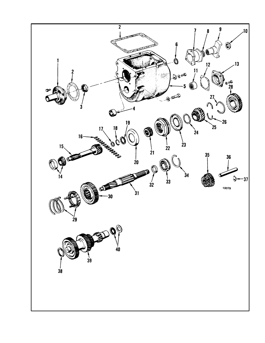
Assembly (See FIGURE 12.)
1. Apply light grease in the bore of the input shaft gear.
Install the 14 roller bearings in the bore. Slide the last
roller in position. Install the retainer washer and snap
ring.
2. Use a press to install the bearing cone of the input
shaft. Support the race and push the input shaft into the
bearing. See FIGURE 11.
FIGURE 11. INSTALLING THE
INPUT SHAFT BEARING
1. PRESS
2. INPUT SHAFT GEAR
3. TAPERED ROLLER BEARING
4. WOOD BLOCK
10095
3. Assemble the cover if it was disassembled. See
FIGURE 7. Put some grease in the hole in the third and
fourth gear rail. Install the interlock pin in the rail. Install
the plungers into the interlock bores. Hold the selector
fork for third and fourth gear in position on the cover.
Slide the third fourth rail through the spring and ball for
the third and fourth gear rail. Push the ball with a screw-
driver and push the rail past the detent ball and spring.
Align the hole in the fork with the hole in the rail. Install
a new roll pin to fasten the fork to the rail. Move the third
and fourth gear rail to the neutral position.
4. Slide the rail for first and second gear through the hole
in the cover. Hold the fork for first and second rail in
position and slide the rail through the lug. Align the hole
in the lug with the hole in the rail. Install a new roll pin.
Align the hole in the fork with the hole in the rail and
install a new roll pin.
5. Install new plugs in the holes in the cover. Apply seal-
ant around the holes and hit the center of the plugs with a
drift.
6. Use a press to install the needle bearing for the cluster
gear into the case. Push on the bearing until the end of
the end of the bearing is even with the surface of the
case.
7. Install the needle bearing in the bearing retainer for
the cluster gear. Push the bearing into the bearing retain-
er until the bearing is even with the surface for the gas-
ket.
8. Install a new seal in the retainer for the input shaft
bearing. The lip of the seal must be toward the transmis-
sion.
9. Use a press to install the cup for the input shaft bear-
ing. Push the cup until it is against the shoulder of the
bearing retainer.
10. Install the seal for the output yoke in the mainshaft
bearing retainer. The lip of the seal must be toward the
transmission. Press the seal against the shoulder.
11. Lubricate the bearings for the cluster gear with gear
oil. Use a light grease to hold the thrust washer for the
cluster gear in position on the case. Make sure the thrust
washer aligns with the notches in the case. See
FIGURE 13. Install the cluster gear into the case. Lubri-
cate the thrust bearing and race. Slide the thrust bearing
and race on the cluster gear.
9
FIGURE 12. PARTS OF THE MANUAL TRANSMISSION
1. BEARING RETAINER
2. GASKET
3. SEAL
4. NEEDLE BEARING
5. CASE
6. SPACER
7. MAINSHAFT BEARING RETAINER
18. SNAP RING
19. THRUST BEARING
20. SYNCHRONIZER STOP RING
21. HUB
22. SYNCHRONIZER ASSEMBLY
23. SYNCHRONIZER STOP RING
24. SHIM
25. THIRD GEAR
26. SPECIAL SNAP RING
27. SNAP RING
28. SECOND GEAR
29. SYNCHRONIZER RING AND
SPRING
30. FIRST GEAR
31. MAINSHAFT
32. SPACER
33. BALL BEARING
34. SNAP RING
35. REVERSE GEAR
36. SHAFT
37. RETAINER
38. THRUST WASHER
39. CLUSTER GEAR
40. THRUST BEARING AND RACE
8. SEAL
9. YOKE
10. NUT
11. NEEDLE BEARING
12. GASKET
13. BEARING RETAINER
14. TAPERED ROLLER
BEARING
15. INPUT SHAFT
16. ROLLER BEARINGS
17. WASHER
10
FIGURE 13. ALIGN THE THRUST
WASHER WITH THE NOTCHES
10087
12. Install a new gasket on the bearing retainer for the
cluster gear. Lubricate the bearing cup with gear oil.
Install the bearing retainer and tighten the capscrews to
20 to 35 N.m (15 to 25 lbf ft). See FIGURE 14.
FIGURE 14. INSTALLING THE BEARING
RETAINER FOR THE CLUSTER GEAR
10086
13. Assemble the second gear synchronizer and spring
into second gear. See FIGURE 16. Install the snap ring
with the ends of the snap ring away from the gear. Put the
mainshaft in a vise with soft jaws with the input end of
the shaft up.
14. Lubricate the second gear assembly with oil and
install it on the input end of the mainshaft. Install second
gear with the synchronizer toward the output end of the
mainshaft. Install the special snap ring in the groove on
the mainshaft.
15. Install third gear on the mainshaft with the splines
up. Install the synchronizer stop ring on third gear.
Install the synchronizer hub on the mainshaft as shown
in FIGURE 16. Install the synchronizer assembly and
stop ring on the mainshaft.
FIGURE 15. SYCHRONIZER ASSEMBLY FOR
SECOND GEAR
1. SECOND GEAR
2. PIN
3. SPRING
4. SYCHRONIZER RING
5. SPLINES
6. RIVET
7. SNAP RING
10083
11
FIGURE 16. INSTALL THE HUB WITH THE
OIL GROOVE TOWARD THIRD GEAR
10090
16. Install the thrust bearing. Temporarily install the in-
put shaft with the synchronizer stop ring on the end of
the mainshaft. Measure the clearance between the syn-
chronizer stop ring for fourth gear and the teeth on the
input shaft gear. See FIGURE 17. The clearance must
be 1.6 to 2.1 mm (0.063 to 0.081 in). If the clearance is
greater than 2.1 mm (0.081 in), put shims between the
third gear teeth and the synchronizer stop ring. When the
clearance is correct, remove the input shaft and thrust
bearing from the mainshaft.
FIGURE 17. CHECK THE CLEARANCE
BETWEEN THE STOP RING AND GEAR
10088
17. Remove the mainshaft from the vise. Slide first gear
on the output end of the mainshaft. The groove for the
selector fork must be toward the output end of the main-
shaft. Install the spacer against the splines of the main-
shaft.
18. Hold first gear and the spacer to prevent them from
falling from the mainshaft. Tilt the output end of the
mainshaft and slide it into the bore for the mainshaft
bearing.
19. Put a wood block between the input end of the main-
shaft and the case. Use a large hammer and a piece of
pipe to install the bearing on the mainshaft.
See FIGURE 18. Make sure the pipe touches only the
inner race of the bearing. The yoke can also be used to
install the mainshaft bearing. Tighten the mainshaft nut
to push the yoke, spacer and bearing onto the mainshaft.
Remove the nut, yoke and spacer.
FIGURE 18. INSTALLING THE
MAINSHAFT BEARING
1. WOOD BLOCK
2. MAINSHAFT
3. MAINSHAFT
BEARING
4. PIPE
10094
20. Remove the wood block. Align the mainshaft so that
the bearing will fit into the bore in the block. Use a plas-
tic hammer to move the outer race into the case.
21. Install a new gasket on the mainshaft bearing retain-
er. Install the mainshaft bearing retainer on the case.
Tighten the capscrews to 20 to 35 N.m (15 to 25 lbf ft).
Put the transmission in two gears at once. Slide the
spacer and yoke onto the mainshaft. See FIGURE 19.
Install the nut and tighten to 120 to 175 N.m (90 to 130
lbf ft).
22. Install the thrust bearing on the input end of the
mainshaft. Install the input shaft into the mainshaft. Ro-
tate the input shaft so that the notch in the splines is
12
above the teeth of the cluster gear. Temporarily slide the
bearing retainer on the input shaft. Do not install the gas-
ket at this time.
23. Measure the clearance with thickness gauges be-
tween the bearing retainer and the case. Install enough
gaskets so that the thickness of the gasket set is 0.25 to
0.43 mm (0.010 to 0.017 in) thicker than the measured
clearance. The input shaft must have a clearance of 0.18
to 0.35 mm (0.007 to 0.014 in) when the bearing retainer
is installed with the gasket set. Tighten the capscrews to
20 to 35 N.m (15 to 25 lbf ft).
FIGURE 19. MAINSHAFT YOKE ASSEMBLY
1. BALL BEARING
2. MAINSHAFT BEARING RETAINER
3. SPACER
4. SEAL
5. YOKE
6. UNIVERSAL JOINT
7. SPECIAL CAPSCREWS
8. NUT
9. MAINSHAFT
24. Install a new gasket for the transmission cover. Put
the sliding sleeves in theNeutral position. Put the re-
verse gear in theNeutral position. Make sure the rails are
in the Neutral position. Install the cover on the transmis-
sion. Make sure the forks align with the sliding sleeves
and reverse gear. Find the two capscrews that have
shoulders.
25. Put lockwashers on the capscrews with shoulders
and install the capscrews in the two holes nearest the
lugs. Tighten the two capscrews to 25 to 55 N.m (20 to
40 lbf ft). Install the other 6 capscrews for the cover.
Tighten the capscrews to 25 to 55 N.m (20 to 40 lbf ft).
Move the rails with a screwdriver to check their opera-
tion. Turn the input shaft and check the operation of the
mainshaft for each gear.
Installation, H6.00–7.00XL (H135–155XL)
1. Move one of the rails so that a gear is engaged. Use a
lifting device to move the transmission to the level of the
clutch.
2. Apply a sealant (Hyster Part No. 264159) to the flange
of the engine adapter.
3. Move the clutch housing toward the engine adapter.
Rotate the yoke until the splines of the input shaft are en-
gaged with the splines of the clutch disc. Push the trans-
mission toward the clutch until the input shaft is in the
pilot bearing. The clutch housing must be touching the
engine adapter. Tighten the capscrews at the clutch
housing to 31 N.m (23 lbf ft).
CAUTION
Do not use the capscrews for the clutch housing to
pull the housing to the engine adapter.
4. Install the engine mounts on the clutch housing.
Tighten the capscrews for the mounts to 110 N.m (80 lbf
ft). Install the capscrews that hold the engine mounts to
the frame. Tighten the capscrews to 66 N.m (49 lbf ft).
5. Slide the yoke of the drive shaft into the speed reduc-
er. Hold the universal joint assembly against the yoke of
the transmission. Apply a thread locking compound to
the threads of the capscrews. Tighten the, capscrews in a
cross pattern to 28 N.m (20 lbf ft). Tighten the caps-
crews again to 28 N.m (20 lbf ft).
6. Connect the oil lines at the clutch housing.
7. Install the spring, spring retainer, cap and rubber cov-
er on the selector lever. See FIGURE 4. Apply a small
13
amount of grease on the ball of the selector lever. Install
the lever assembly on the transmission cover. Make sure
the rails are in Neutral. Align the slots in the cap with the
pins on the transmission cover. Push on the cap and ro-
tate the cap so that the pins hold the cap in position.
Install the knob on the selector lever.
8. Remove the fill plug from the side of the case. Fill the
transmission with SAE 80W–90 or 85W–140 gear oil
until oil drains from the fill hole. The capacity of the
transmission is 3.3 litres (3.5 qt). Install and tighten the
plug. Install the floorplates.
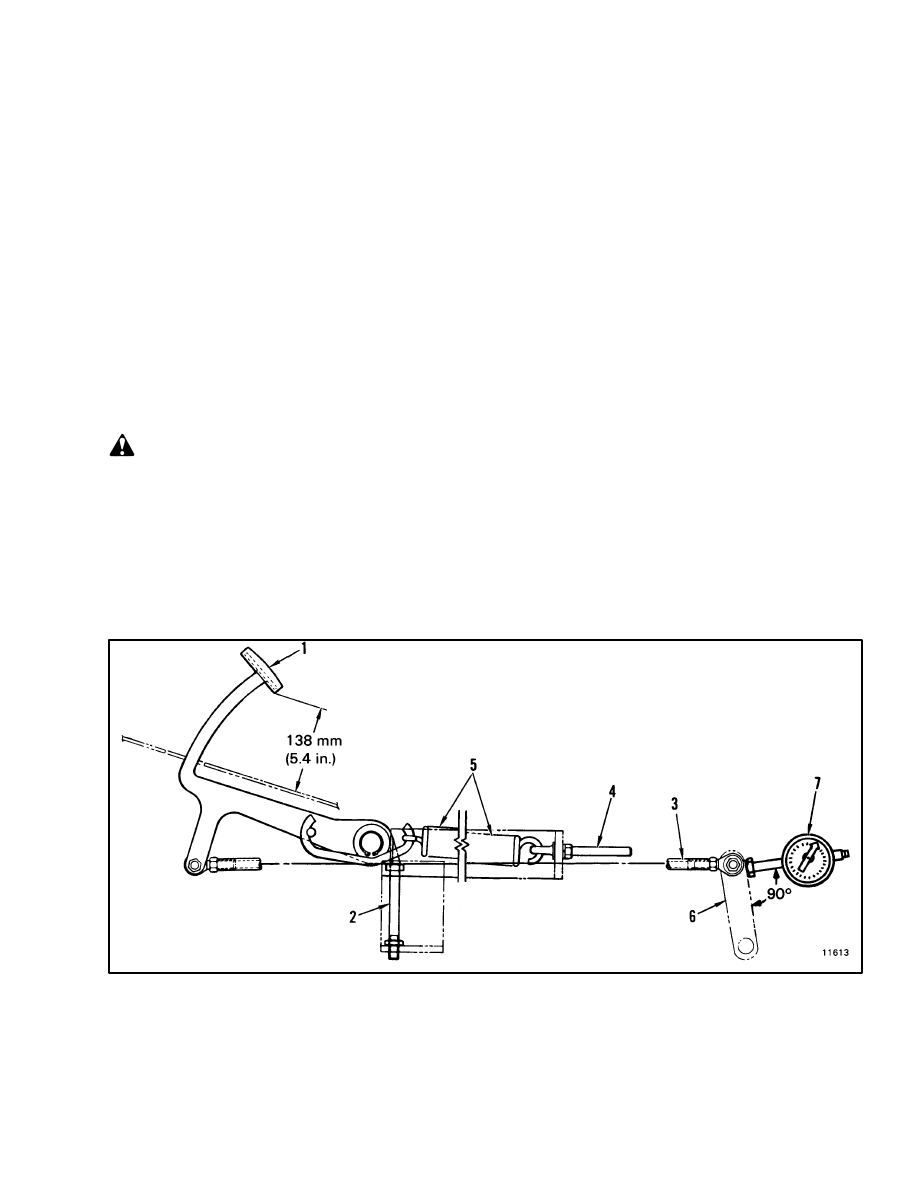
CHECKS AND ADJUSTMENTS
ADJUSTING THE CLUTCH PEDAL
LINKAGE, H6.00–7.00XL (H135–155XL)
(See FIGURE 20.)
1. Adjust the height of the clutch pedal to 138 mm (5.4
in) using the stop screw. Use the lock nut to keep the stop
screw in position.
WARNING
Do not remove any parts of the clutch linkage with-
out releasing the tension on the springs. Loosen the
eyebolts to release tension on the springs.
2. Loosen the eyebolts and remove the pedal return
springs. Install a dial indicator to measure the move-
ment of the crank for the release shaft. Make sure the
dial indicator is installed so that it is 90
°
to the crank.
3. Rotate the crank clockwise by hand until the release
bearing touches the fingers on the pressure plate. Set the
dial indicator to zero.
4. Install the clutch link, eyebolts and pedal return
springs.
5. Adjust the length of the clutch link until the needle on
the dial indicator moves 1.8 mm (0.071 in) counter-
clockwise. Tighten the rod ends without changing the
adjustment. This adjustment is necessary to give clear-
ance between the release bearing and the fingers on the
pressure plate.
6. Push on the clutch pedal to make sure the clutch link
and pedal return springs do not touch other parts.
FIGURE 20. CLUTCH PEDAL LINKAGE
1. CLUTCH PEDAL
2. STOP
3. CLUTCH LINK
4. EYEBOLTS
5. PEDAL RETURN SPRINGS
6. CRANK FOR RELEASE SHAFT
7. DIAL INDICATOR

14
TROUBLESHOOTING–OIL CLUTCH ASSEMBLY
PROBLEM
POSSIBLE CAUSE
The clutch does not engage smoothly
Loss of oil to the clutch.
Release linkage is damaged or needs adjustment.
Eyebolt for booster spring is not tightened.
Adjustment of pedal is wrong.
Friction surface of pressure plate is damaged.
Friction surface of flywheel is damaged.
Springs in pressure plate are damaged.
Disc material is worn or damaged.
Clutch disc is bent.
Pressure plate levers are not adjusted correctly.
Pressure plate levers are damaged.
Oil nozzle is damaged.
Capscrews for pressure plate cover are loose.
Flywheel capscrews are loose.
The clutch does not hold.
Pedal does not return to stop.
Clutch disc is worn.
Linkage is not adjusted correctly.
Springs for pressure plate are damaged.
Pressure plate levers are damaged.
Friction surface of pressure plate is damaged.
Friction surface of flywheel is damaged.
Loss of oil to the clutch.
The clutch engages suddenly.
Disc material is worn or damaged.
Pressure plate levers do not operate correctly.
Splines on clutch disc are damaged.
Loss of oil to the clutch.
Clutch disc is installed wrong.
Clutch release mechanism is damaged.

15
PROBLEM
POSSIBLE CAUSE
The clutch does not release.
Linkage is not adjusted correctly.
Disc material is damaged.
Release fork or shaft is damaged.
Splines on clutch disc are damaged.
Splines on clutch shaft are damaged.
Pilot bearing is damaged.
Pressure plate levers do not operate correctly.
Release fork is installed wrong.
Noise when clutch pedal is pushed.
Release bearing is damaged.
Pilot bearing is damaged.
Clutch disc is damaged.
Springs in pressure plate are damaged.
Pedal shaft needs lubrication.
Flywheel capscrews are loose.
Crankshaft clearance is not correct.
Noise when clutch pedal is not pushed.
Pilot bearing is damaged.
Noise from transmission.
Linkage is not adjusted correctly.
Flywheel capscrews are loose.
Clutch pedal does not return to stop.
Linkage is not adjusted correctly.
Pedal shaft is damaged or needs lubrication.
Clutch linkage is damaged.
Pressure plate levers are damaged.
Release fork is installed wrong.
Loss of oil to the clutch.

16
TROUBLESHOOTING–MANUAL TRANSMISSION
PROBLEM
POSSIBLE CAUSE
Transmission makes noise when changing gears.
Low oil level.
Synchronizer rings are worn
Synchronizer assemblies are worn or damaged.
Clutch does not fully release.
Splines on gears are worn.
Splines on sliding sleeve are worn.
Lift truck is moving when selecting first gear.
Pilot bearing is damaged.
Wrong type of oil.
Transmission is noisy.
Low oil level.
Worn bearings.
Worn or broken gears.
Worn thrust washers.
Tapered roller bearing adjusted wrongly.
Bearing retainer capscrews are loose.
Transmission has oil leaks.
Too much oil in transmission.
Wrong type of oil.
Capscrews are loose.
Gaskets are damaged.
Seals are damaged or worn.
Seals are installed wrong.
Surfaces for seals are damaged or worn.
Transmission disengages, selector lever moves.
Worn splines on gears.
Worn splines on sliding sleeve.
Worn or bent forks.
Bearings are worn or adjusted wrongly.
Detent springs or balls worn.
Rails are worn.
Snap ring is broken.
Loose capscrews on retainer.
Transmission and clutch housings are not aligned.
17
PROBLEM
POSSIBLE CAUSE
Selector lever is difficult to move.
Clutch does not fully release.
Synchronizer assemblies are worn or damaged.
Rails are damaged.
Interlock pin is missing or damaged.
Interlock plungers are damaged.
Splines on gear are damaged.
Splines on sliding sleeve are damaged.
Wrong type of oil.
Pins for selector lever are broken.
Forks are bent.
Transmission and clutch housings are not aligned.
Low oil level.
Wrong type of oil.
Oil is too cold.
Document Outline
- INTRODUCTION
- REPAIRS
- CHECKS AND ADJUSTMENTS
- TROUBLESHOOTING-OIL CLUTCH ASSEMBLY
- TROUBLESHOOTING-MANUAL TRANSMISSION
Wyszukiwarka
Podobne podstrony:
897656 1300SRM0568 (10 1999) UK EN
1538373 2200SRM1065 (02 2004) UK EN
897986 1600SRM0658 (03 1997) UK EN
897509 2200SRM0524 (02 2001) UK EN
897393 1800SRM0452 (02 2004) UK EN
1566279 8000SRM1155 (02 2005) UK EN
910107 2200SRM0106 (02 2001) UK EN
897125 1300SRM0344 (07 1993) UK EN
897988 4000SRM0660 (05 1997) UK EN
910466 5000SRM0266 (11 1997) UK EN
897989 4000SRM0661 (02 2004) UK EN
897985 1400SRM0657 (05 1997) UK EN
897996 5000SRM0668 (05 1997) UK EN
897594 2200SRM0550 (02 2001) UK EN
więcej podobnych podstron