
111. CALCULATION OF THE PRESTRESSING FORCE
Calculation of the prestressing force in the tendon
To carry out this calculation, one must first establish two distinctly different stages :
• Tensioning stage
The stresses in the tensioned tendon result from the force exerted by the jack and from the internal friction
between the tendon and, on the one hand, the anchorage and, on the other, the duct. Their determination
enables the calculation of theoretical elongations, which must be recorded during tensioning. The value of
the initial stress after removal of the jack is assessed by taking into account the pull-in.
• Time dependent stress variation
The stress in the tendon varies continually with the process of time, due to the occurrence of phenomena ty-
pical of the structural concrete, i.e. shrinkage and creep, as well as steel relaxation. Therefore, these phe-
nomena must be taken into account to determine the actual stress condition of the tendon at any time.
111.1 Forces and stresses exerted during tensioning
According to the 1990 CEB-FIP Model-Code, the stress
s
po
(x), in a section located at a distance x from the
live anchorage, is lower than the stress
s
po, max
; the difference between the two stresses corresponds to the
friction losses. The value of
s
po
(x) can be calculated using the following relationship:
s
po
(x) =
s
po, max.
e
–
m(a + kx)
where:
e = Base of Naperian logarithms.
m = Friction coefficient between prestressing steel and duct.
a = Sum of angular deviations over the distance x, independent of their direction and sign (spatial outline).
k = Unintentional angular deviation, per unit length.
This can also be expressed as follows:
s
x
=
s
o
e
–
m(u + kx)
or again:
s
x
=
s
o
e
–(
ma + wx)
in which:
a = u and w = k m
The friction coefficient
m is also known as f. The relationship is then usually expressed as follows:
s
x
=
s
o
e
–(f
a + wx)
or, again:
s
po
(x) =
s
po
e
–f
a – wx
where:
s
po
(x) = Tension in a given section
s
po
= Tension at the live anchorage.
111.11 Radii of curvature, friction coefficients and unintentional angular deviations
The friction coefficients depend on the type of steel used, the nature of the duct and the surface condition
of each material. The accepted values and tolerances vary according to the origin of the statutory texts.
PAGE 1/16

111. CALCULATION OF THE PRESTRESSING FORCE
111.111 T
ENDONS WITH AN OVERALL DUCT
– I
NFORMATION
B
ULLETIN N
° 204
OF THE
1990 CEB-FIP M
ODEL
-C
ODE RECOMMENDS
:
• In the case of internal prestressing
The friction coefficient
m is the product of the coefficient m
o
with a compaction rate
x varying according to
the rate at which the tendon fills the duct. It may vary from 1.30 to 1.35 with a filling rate of 50% to 60%.
Strands:
m
o
= 0.15
m = 0.19
High bond bars:
m
o
= 0.50
m = 0.65
Plain bars:
m
o
= 0.25
m = 0.33
The permitted variations are in the region of a 50% maximum. In case of rust, higher discrepancies are
accepted. The coefficient
m can be multiplied by 0.9 in the case of a protection using soluble (emulsi-
fiable) oil.
Regarding the rate of unintentional angular deviation, one should take into account 0.005
≤
k
≤
0.010
radians per metre.
• In the case of external prestressing
The CEB-FIP document considers the following value, with regard to saddles with radii between 2 500 and
4 000 mm:
k = 0
Bare and dry strands on a steel saddle: 0.25
≤
m
≤
0.30
Greased strands on a steel saddle: 0.20
≤
m
≤
0.25
Bare and dry strands within a plastic tube, on a steel saddle: 0.12
≤
m
≤
0.15
Bundles of monostrands with plastic sheath, on a steel saddle: 0.05
≤
m
≤
0.07
• The ACI 318 Code gives the following indications, for oiled strands:
0.15
≤
f
≤
0.25
0.0005
≤
w
≤
0.0020 per foot (i.e. about 0.0015 to 0.0060 per m.)
• BS 8110 indicates in turn:
Steel/concrete: f = 0.55
Steel/steel: f = 0.30
Steel/galvanized steel: f = 0.25
w = 0.0033 per m or 0.0017 per m in the case of rigid sheaths unlikely to move during concreting.
• Eurocode 2 suggests the following values:
Cold drawn wires:
m = 0.17
Strands:
m = 0.19
High bond bars:
m = 0.65
Plain bars:
m = 0.33
0.005
≤
k
≤
0.010 radians per m.
Note:
We give below, for information, the values indicated by the French code.
PAGE 2/16

111. CALCULATION OF THE PRESTRESSING FORCE
C
OEFFICIENTS
f
AND
w
BPEL 91 suggests the following mean values, in the case of tendons and sheaths which are neither oxidi-
sed nor misshapen, protected by oil or grease coating. The permitted variations are in the region of a 25%
maximum.
Type
f
Case
of tendons
3
≤
R
≤
6 m
R
≥
6 m
w(m
-1
)
I - Tendons not running through
Round and plain
22 - R
0.16
0.002
construction or other joints
drawn wires
100
Strands
24 - R
0.18
0.002
100
II - Tendons running through many
Round and plain
24 - R
0.18
0.003
construction or other joints
drawn wires
100
Strands
26 - R
0.20
0.003
100
R
ADII OF CURVATURE
• According to Fascicule 65 A, one should consider the following:
Rigid, sheet metal sheaths, bendable by hand: R
≥
100 Ø
i
. Where Ø
i
is the internal diameter of the duct.
Windable sheaths and steel tubes: R
≥
3 000 mm.
The radius may exceptionally be decreased, providing that:
– 20 Ø
i
≤
R
≤
3 000 mm.
– the tendon tension does not exceed 0.7 F
pk
at the beginning of the curve;
– the total of angular deviations
(a
≤
3
p/2 radians;
– the sharply curved zone is considered as a dead-end anchorage when the angular deviation is greater
than
p/2.
• Special Fascicule 86-19 bis recommends the following values for the friction coefficient f, in the case of
smooth tubes:
Bare strands and steel tube, clean and oiled: 0.20
≤
f
≤
0.30.
Bare, clean strands and HDPE tube: 0.12
≤
f
≤
0.15.
The adoption of minimum values, for f, must be in compliance with the following criteria: an installation drawing for
the sheaths, a strict control and the complete absence of any angular point at the connections with straight parts.
w = 0 when the wires or strands are parallel to each other and the ducts are correctly aligned.
111.112 T
ENDONS OUT OF UNBONDED STRANDS
– I
NFORMATION
B
ULLETIN N
° 204
FROM THE
1990 CEB-FIP M
ODEL
-C
ODE RECOMMENDS
:
m = 0.05 to 0.07
k = 0.006 to 0.01 m
–1
Note :
We give below, for information, the values specified in the French Code (BPEL 91).
Providing the installation is carried out with a minimum care and if the radii comply with the following rule:
Isolated strands: R
≥
1 000 m
Bundled strands: R
≥
2 000 m
One may take:
f = 0.05
w = 0.001 m
–1
w = 0 when the wires or strands are parallel to each other and the ducts are correctly aligned.
PAGE 3/16
111. CALCULATION OF THE PRESTRESSING FORCE
111.113 N
OMOGRAPHS
The nomographs n°1 and 1 bis permit the calculation of
ma and wx according to the coefficients chosen for
m and w and to the values of a and x, as measured from the drawings. Nomograph n°1 bis is an enlargement
of nomograph n°1, near the origin. They are read using the values of
a expressed in degrees and of x, in m.
Knowing (
ma + wx), the nomograph n°2 permits the direct determination of w
x
by drawing the straight line
linking the point corresponding to
s
o
to the point corresponding to (
ma + wx) on the scale (ma + wx).
The scale
s
m
the gives an average value between
s
o
and
s
x.
Calculation of
ma and
w
x
-
Nomograph N°1
PAGE 4/16
a in degrees
0°
25°
50°
75°
100°
125°
150°
ma
ma
+
wx = 0.296
wx
32.75
85°
0.22
0.20
m = 0.18
0.16
0.267
0.50
0.40
0.30
0.20
0.10
0.029
20
25°
50°
75°
100°
125°
0.0005
0.0007
0.0011
0.0013
0.0015
w = 0.0009/m
40
60
80
100
120
140
0
0.10
0.20
x in m
0
10
20
30
40
50
60
70
80
90
100
110
120
130
140
150
Nomograph
N°1 bis
111. CALCULATION OF THE PRESTRESSING FORCE
Calculation of
ma and
w
x
-
Nomograph N°1bis
PAGE 5/16
0.22
0.20
m = 0.18
0.16
0.0005
0.0007
0.0011
0.0013
0.0015
w = 0.0009/m
a in degrees
x in m
ma
wx
5°
10°
15°
20°
22°
25°
30°
5
10
15
20
25
30
0.15
0.10
0.05
0
0.05
0.069
0.018
5°
10°
15°
20°
25°
30°
ma
+
wx = 0.087
111. CALCULATION OF THE PRESTRESSING FORCE
Calculation of
s
x
and
s
m
in N/mm
2
- Nomograph N°2
PPC
111/
1-
02.95
PAGE 6/16
ma + wx
0
0.05
0.1
0.2
0.3
0.296
0.4
0.5
1.0
example
example
986
1 258
1 158
1 314
s
x
200
400
600
800
1 000
1 200
1 400
s
0
200
400
600
800
1 000
1 200
1 400
1 330
1 370
s
m
200
400
600
800
1 000
1 200
1 400
111. CALCULATION OF THE PRESTRESSING FORCE
111.12 Pull-in of jaws
Functioning of an anchorage with conical jaws
The loss of elongation occurs when the force exerted by the jack on the tendon is directly transferred
through the anchorage to the structure. This transfer takes place when the jack tensioning chamber is being
drained. The energy required to complete the conical tightening is only reached after a feeding motion
from the strand, pulling in the jaw; the pull-in can be diminished by carrying out a prior hydraulic locking,
using an auxiliary jack. The values of the jaw pull-in are indicated in the tables giving the technical cha-
racteristics of each anchorage.
The drop in tension in the anchoring zone is often advantageous, since it permits the elimination of the mo-
mentary overtensioning necessary to reach the desired tension in the important sections of the structure.
Calculation the tension after locking
During the conical locking, the returning motion of the tendon is hampered by the friction with the sheath; this is the
opposite phenomenon to that observed during tensioning. The drop in tension, which is maximum at the anchorage,
decreases progressively and symmetrically (tensioning diagram) and ceases at a distance d from the anchorage.
Before the pull-in, the tension at the abscissa x
was given by the formula
(1) :
•
s
p
(x) =
s
p0
e
– (f
a + wx)
(1)
which can be expressed:
•
s
p
(x) =
s
p0
e
– K (x)
(2)
K(x) depicting the increasing function of x:
(f
a + wx).
The value of the relative elongation of the tendon at
the distance x was :
•
e
p
(x) =
s
p
(x)
(3).
E
p
After occurrence of the pull-in, the tension at the
abscissa x (< d) is only:
•
s’
p
(x) =
s
p
(d) e
– [K(d) – K(x)]
(4)
or, taking
(2) into account:
•
s’
p
(x) =
s
p0
e
– [2K(d) – K(x)]
(5)
and the elongation:
•
e’
p
(x) =
s’
p
(x)
(6).
E
p
Let us assume that g is the sum of the elongation losses [
e
p
(x) –
e’
p
(x)] dx of the segments dx between 0 and D, i.e.:
• g =
* [e
p
(x) -
e’
p
(x)] dx
(7).
g = 1
* [s
p
(x) –
s’
p
(x)] dx
(8).
E
p
The integral represented in the relationship
(8) reflects the shaded area of the figure. Equation (8), taking into
account
(2) and (5), permits the determination of d, therefore of
s’
p
(x), or, similarly, the loss due to anchorage
pull-in :
•
s
g
(x) =
s
p
(x) –
s’
p
(x)
(9).
PAGE 7/16
Fig. 1 – Tension along the tendon before and after releasing the
pressure of the jack
d
0
d
0
distance from anchorage x
d
s
p
(x)
s'
pog
s
po
s
p
(x)
s'
p
(x)
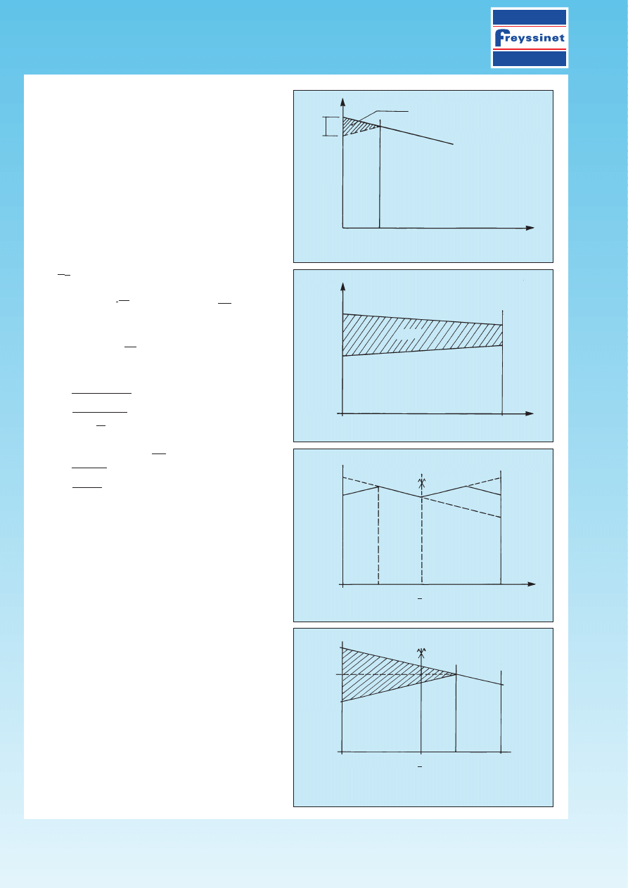
111. CALCULATION OF THE PRESTRESSING FORCE
In practice, the following reasoning is often prefe-
rable: the quantity gE
p
represents the surface area
of the shaded curvilinear triangle in fig. 1. By equa-
ting the exponential branches with straight lines, the
loss due to anchorage pull-in can be assessed from
the surface area of the triangle formed by the inter-
section of the tensioning diagrams before and after
anchoring the tendon considered (see fig. 2).
Taking into account friction over the distance d, inso-
far as the tendon of length l is tensioned from one
end only and its total angular deviation over the length
l
is
a, which is tantamount to a mean angular devia-
tion ad over the distance d, the following is verified:
l
s’
p0
=
s’
p0
.e
–2(fad +
wd)
≈
s
p0
[ 1–2d.(fa +
w)]
l
l
hence:
s
p0
–
s’
p0
= 2d. (fa +
w). (10)
l
Therefore, the surface area of the triangle is:
gE
p
= d
2
(f
a/l + w) s
p0
:
d =
=
gE
p
(11)
s
p0
(fa +
w)
l
or again, assuming k = fa +
w :
l
d =
=
gE
p
(12)
s
p0
.k
The value of
s’
p0
is immediately obtained using
(10).
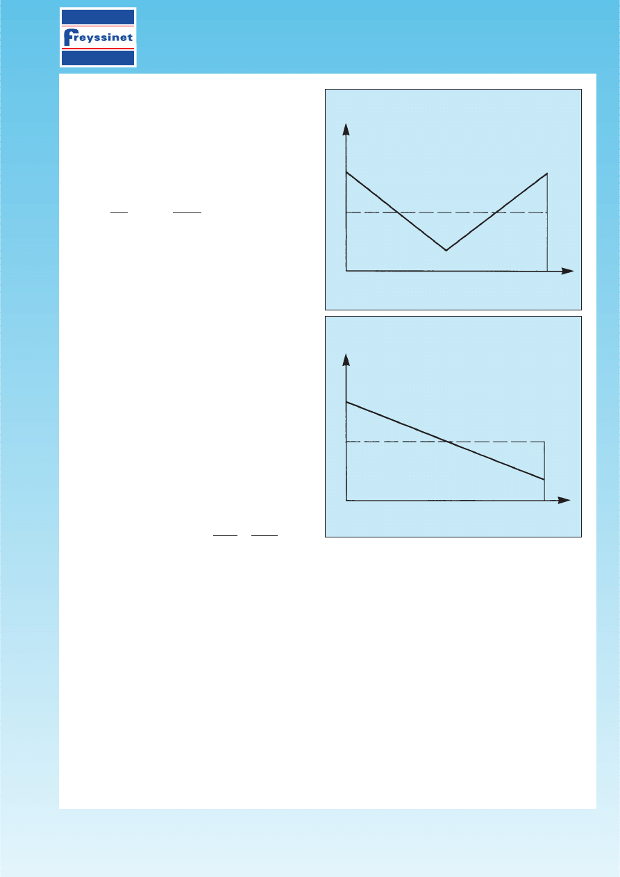
If the pull-in affects the entire length of the ten-
don, there is, because of the symmetry, a loss
of tension as shown in fig. 3:
– if d
≤
l
/2, the tendon must be tensioned from
both ends in order to reach tensions greater than
those obtained with a tensioning carried out from
one end only (see fig. 4);
– if d > l /2, it is preferable to tension the tendon
from one end only, the tensions obtained being
thus higher (see fig. 5).
The transverse prestressing of bridge decks (short
tendons, for which the pull-in can affect a length
greater than l /2) is most often achieved by ten-
sioning the tendons from one end only, the live
end being alternate from one tendon to the other.
The average tension of tendons may then be
considered as constant and equal to the value
s
m
obtained in the median section.
PAGE 8/16
Fig. 2 – Diagram of tensions before and after anchoring the
tendon. Effect of anchorage slip.
Fig. 3
Fig. 4
Fig. 5 – Tensioning of the prestressing tendon from one end only.
x
d
O
Ds
gO
s
pO
s'
pO
s
d
gE
p
s
s
pO
s
pl
s'
pl
gE
p
s'
pO
s
pO
s
pl
s'
pl
s'
pO
s
pO
s
m
s
s'
pO
O
O
d
d
l
l
l
l
2
l
2
111. CALCULATION OF THE PRESTRESSING FORCE
111.2 Tendon elongation
The effect of the elastic shrinkage of concrete du-
ring tensioning is practically insignificant; it is not
taken into consideration in the following calcula-
tions.
The elongation of the tendon during tensioning is
given by the following:
Dl =
*
l
s
(x)
dx =
*
l
P
(x)
dx
(13), where
E
p
A
p
E
p
Dl = total elongation (sum of the elongations at
both ends),
P
(x)
or
s
(x)
= tension at the point located at a dis-
tance x on the tendon,
E
p
= the tendon modulus of elasticity,
A
p
= the area of the tendon cross-section.
When tensioning is carried out from both ends of
a tendon whose outline is symmetrical with respect
to the median section of the element, the minimum
tension is located at mid-tendon (see fig. 6); when
it is achieved from one end only (see fig. 7), the
minimum tension is at the dead-end anchorage.
The tension, when the tendon is being tensioned,
can often be considered as variable in a linear
way along the tendon. In the cases depicted by
figs. 6 and 7, the elongation will therefore be cal-
culated using the mean tension
s
m
, which is the
average between the maximum tension at the an-
chorage and the minimum tension
s
min
;
The elongation is then:
D
l
= P
m
l
= s
m
l
(14)
A
p
E
p
E
p
l
being the distance of the tendon between the fixing points on jacks (see fig. 6), or between the fixing
point on a jack and the dead-end anchorage (see fig. 7).
111.3 Final prestressing force
The tension in prestressing tendons drops, due to the instantaneous shortening of the structure, and the time-
dependent shrinkage and creep effects on the concrete; the relaxation of prestressing steel comes in addi-
tion to these phenomena. Therefore, the sum of the losses resulting from all these phenomena must be ob-
tained, in order to assess the final value of the prestressing force when designing the structure. The
formulae permitting the calculation of the losses are given in the national or international codes such as
Eurocode 2, the CEB-FIP Recommendations or the French regulations (BPEL 91), for example.
PPC
111/
1-
02.95
PAGE 9/16
Fig. 6
Fig. 7
s
min
s
min
x
P
0
P
(x)
ou
s
(x)
P
0
P
m
x
s
(x)
P
0
P
m
s
0
s
m
s
0
P
min
s
0
s
m
P
min

111. CALCULATION OF THE PRESTRESSING FORCE
111.31 Instantaneous deformation of concrete
The loss of prestress caused by the structure instantaneous shrinkage, following the action of the force exer-
ted by the prestressing tendons and the other permanent actions, is not considerable. It can be equated to a
mean loss affecting each tendon, amounting, in a given section, to the following, according to the French
code BPEL 91:
E
p
(
k
Ds
bj
(15)
E
ij
•
Ds
bj
being the variation of stress in the concrete occurring at the level of the centre of gravity of the pres-
tressing tendons in the section considered, under the varying permanent actions exerted on day j.
In practice, when the stress variations remain limited, a sufficient estimation of the loss due to instantaneous
deformations of concrete can generally be obtained by assuming it to be equal to 6k
s
b
(16) -
s
b
represen-
ting the final stress of concrete.
• and k a multiplying coefficient equal to:
– 1/2 for the stress variations due to the relative prestress during the tensioning phase of the tendons consi-
dered and to the permanent actions simultaneously exerted.
– 1 for the stress variations due to the permanent actions exerted following this tensioning phase, including
those due to prestressing tendons subsequently tensioned.
In the case of n similar tendons tensioned one after the other, the coefficient k is actually equal to
(n – 1)/2n. It draws closer to 1/2 when the number of tendons is higher.
111.32 Concrete shrinkage
Shrinkage is the shortening of the unloaded concrete, during its hardening. The prestressing tendons, tightly
bonded to the concrete, are therefore subject to the same variations of deformation as the adjacent concrete.
The final loss of tension due to concrete shrinkage, in the case of constant thermic and hygrometric condi-
tions, depends on the age of the concrete at the moment of tensioning, of the total concrete shrinkage and
of its development in time.
The final loss of tension due to shrinkage, for the considered tendon, is the following, according to the French BPEL 91
code:
Ds
r
= E
p
«
r
[1 – r (t
0
)]
(17)
with E
p
= Modulus of elasticity of steel,
«
r
= Final shrinkage deformation and r(t
0
) = Function reflecting the
law of time-dependent shrinkage development.
r (t
0
) can often be ignored, hence the following simplified formula :
Ds
r
≈
E
p
«
r
.
(18)
111.33 Concrete creep
Deformation by creep is caused by a time-dependent shortening of concrete due to compressive stresses.
The final loss of tension due to concrete creep, in the case of constant thermic and hygrometric conditions, de-
pends on the maximal stress and on the final stress withstood by the concrete in the zone considered, on the
age of concrete at the moment of tensioning, as well as the duration and magnitude of the loading.
According to the French BPEL 91 code, the final loss of tension the reinforcement is subject to is the fol-
lowing:
Ds
fl
= E
p
«
fl
≈
E
p
(
s
max
+
s
c
)
(19)
E
ij
Where E
p
= Modulus of elasticity of steel, E
ij
= Modulus of instantaneous deformation of concrete at the age
of j days,
s
max
and
s
c
being the respective maximum stress and final stress withstood by the concrete in the
considered section, at the level of the centre of gravity of the prestressing tendons.
As
s
max
≤
1.5
s
c
and E
p
/ E
ij
≈
6, we can deduce:
s
fl
≈
15
s
c
(20)
PPC
111/
1-
02.95
PAGE 10/16

111. CALCULATION OF THE PRESTRESSING FORCE
111.34 Relaxation of prestressing steel
A tendon permanently tensioned and maintained, after tensioning, at a constant length, is subjected to a loss
of tensile stress. The final value of the loss of tension due to relaxation is dependent on the duration of the
application of the prestressing force, on the guaranteed value of relaxation at 1 000 hours and on the value
of the tendon initial tension. Therefore, when verifying an old structure, the possible influence from a more
important relaxation must be considered, depending on the age of the construction.
The BPEL 91 code proposes the following formula for determining the final loss due to relaxation:
Ds
p
= 6
r
1000
[s
pi
(x) –
m
o
]
s
pi
(x)
(21)
100
f
pk
where:
r
1000
= Guaranteed value of relaxation at 1 000 hours.
s
pi
(x) = Initial stress of the tendon in the section located at a distance x.
f
pk
= Characteristic tensile strength of the tendon.
m
o
is equal to:
0.43 for very low relaxation tendons;
0.30 for normal relaxation tendons;
0.35 for other tendons.
111.35 Time-dependent losses
It is necessary to take into account the interaction of all the previous phenomena.
To take into account this interaction, the BPEL code proposes the indiscriminate reduction of relaxation using
the coefficient 5/6.
Thus, the final time dependent loss becomes the following:
Ds
d
=
Ds
r
+
Ds
n
+ 5
Ds
p
.
(22)
6
When an assessment of the prestress losses is necessary at any time (for example, in the case of a structure
built in successive steps), the following can be assumed:
Ds
d
(t) = r(t).
Ds
d
r(t) being the function previously defined
r(t) =
t
t + 9.r
m
in which t designates the number of days since the tensioning of the considered element and r
m
the mean
radius of the member section, in cm.
T
ENSION AT ANY TIME
t
In probable value, it is given by the following:
s
p
(x,t) =
s
p0
–
Ds
i
(x) –
Ds
d
(x,t)
or
s
p
(x,t) =
s
p0
–
Ds
p
(x,t)
where
Ds
p
(x,t) represents the total loss of tension at the distance x and at the time t.
The characteristic values of tension are given by:
s
p1
(x,t) = 1.02
s
p0
– 0.8
Ds
p
(x,t)
(23)
s
p2
(x,t) = 0.98
s
p0
– 1.2
Ds
p
(x,t)
(24)
PPC
111/
1-
02.95
PAGE 11/16
111. CALCULATION OF THE PRESTRESSING FORCE
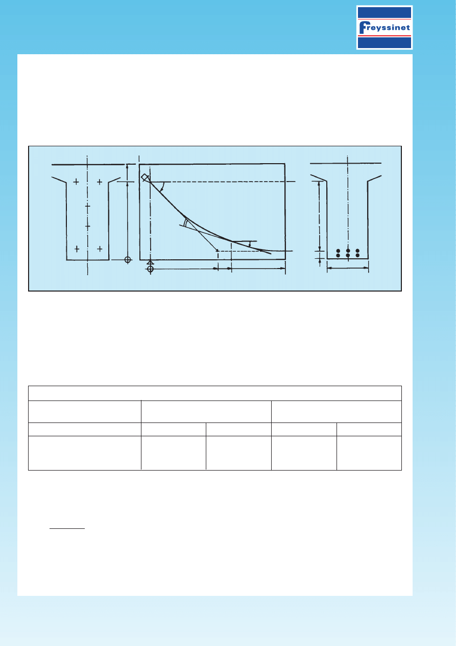
111.4 Example for calculation of losses in a post-tensioned member
(according to “La
Précontrainte” by R. Chaussin, A. Fuentes, R. Lacroix, J. Perchat – Edited by the “Presses de l’École
Nationale des Ponts et Chaussées”).
The cable concerned consists of a parabolic 7 T15 tendon constituting, with five other tendons of the same
type, the prestressing of a 28 m beam.
It lies approximately 0.18 m from the bottom fibre at mid-span and 1.50 m from the same fibre above at the
support (see fig. 9).
The beam, a simple T-shaped member cast using falsework, is made up of concrete with a strength of f
e28
= 30
MPa. The tendons are tensioned when the concrete has reached the age j so that f
ej
= 24 MPa (one can ac-
cept j
≈
14 days). The superstructure is erected at 28 days. A brief calculation, done during the pre-dimensio-
ning design phase, based on an estimation of the mean force transmitted by one T15 strand equal to:
– 0.16 MN all losses achieved (at t =
`),
– 0.16 x 1.2 = 0.192 MN at 14 days,
establishes in the median section, at the level of the centre of gravity of the tendons (at a distance of 0.14
m from the bottom fibre), the following stresses in the concrete (see table below):
Table 1 : Stresses in the concrete adjacent to the tendons
In service (t
`)
In construction (14 j)
P = 6 x 7 x 0.16 = 6.72 MN
P
c
= 1.2 P = 8.06 MN
Stresses (in MPa)
partial
accumulated
partial
accumulated
Prestress P (or P
e
)
16.0
19.2
Dead weight g
– 9.1
6.9
– 9.1
10.1 (=
s
max
)
Superstructure g’
– 3.4 (=
Ds
c28
)
3.5 (=
s
c
)
We intend, using these elements, to estimate the tension of the tendon in the median section, taking into ac-
count the following characteristics.
For T15 tendons in the range 1 770, very low relaxation:
f
prg
= 1 770 MPa
f
pcg
= 220.10
–3
= 1 583 MPa
139.10
–6
r
1 000
= 2.5 %
E
p
= 190 000 MPa.
For the prestressing system used: g = 6 mm.
For friction: f = 0.18 rd
–1
;
w = 2.10
–3
m
–1
.
PPC
111/
1-
02.95
PAGE 12/16
Fig. 9 - Diagram of the tendon.
AA
A
1.80
1.50
0.18
0.65
0o
a(x)
U(x)
De
o
= 1.32
B
BB
x
l
/4
l
/2 = 14.00

111. CALCULATION OF THE PRESTRESSING FORCE
PPC
111/
1-
02.95
PAGE 13/16
• Initial tension
s
p0
= inf
{
0.8 x 1 700 = 1 416 MPa
}
= 1 416 MPa
0.9 x 1 583 = 1 425 MPa
• Immediate losses
– F
RICTION
The angular displacement at a location x (see fig. 9) is:
a(x) = u(x) – u
≈
tan
u (x) – tanu
0
The tendon being parabolic, tan
u (x) =
de
0
is a linear function of x and:
dx
a(x) = ax
a is easily determined with a chosen location of x = l/2
a ( l ) = – u
0
≈
4
De
0
2
l
and: a = 2
a ( l ) = 8De
0
= 8 x 1.32 = 0.0135 m
–1
l
2 l
2
28
2
hence: K (x) = f
a (x) + wx = (0.18 . 0.0135 + 0.002) x = 0.0044 x
i.e.: K (x) = kx with k = 0.0044 m
–1
For x = l/2 = 14 m
s
p
(l/2) =
s
p
0
e
–kl /2
= 1 416 e
–0.0044 . 14
= 1 331 MPa
or:
Ds
p
(l/2) = 1 416 – 1 331 = 85 MPa
In addition, for x = l :
s
p
(l ) =
s
p
0
e
–kl
= 1 416 e
0.0014 . 28
= 1 252 MPa
– A
NCHORAGE SLIP
Let us calculate the length d affected by the pull-in in the anchorage :
We have:
s
p
(x) =
s
p
0
e
–kx
and, according to (5) :
s’
p
(x) =
s
p
0
e
– k ( 2 d – x )
Therefore, the expression (8) becomes: E
p
g =
s
p
0
*
[e
–kx
– e
– k ( 2 d – x )
] dx.
This equation can be strictly solved. In fact, it can be expressed as follows: E
p
g = s
p
0
[1 – e
–kx
]
2
k
hence: e
–kd
= 1 –
=
E
p
gk
s
p0
i.e.: d = – 1 Log
[
1 –
=
E
p
gk
]
= – 1 Log
[
1 –
=
190 000.6.10
–3
.0.0044
]
k
s
p0
0.0044
1 416
hence: d = 13.95 m.
The application of formula
(12) would have led to the following: d =
=
E
p
g =
=
190 000.6.10
–3
≈
13.50 m
s
p0
k 1 416.0.0044
which is about the same result as in the previous calculation, but with a significant difference which
shows that it is misleading to be over-precise in this type of estimation.
d
0
111. CALCULATION OF THE PRESTRESSING FORCE
PPC
111/
1-
02.95
PAGE 14/16
In the following, we will consider the value d = 13.95 m, theoretically more precise.
It can be seen that the effect of the anchorage pull-in is noticeable almost up to the middle of the beam.
At 0, after pull-in, the tension is the following:
s’
p0
=
s
p0
e
–2kd
= 1 416 x e
–2 x 0.0044 x 13.95
= 1 252 MPa.
Thus (see fig. 10), after depressurizing the jack
chamber, the tension is approximately symmetri-
cal in relation to the median section, which shows
that it is useless to tension the tendon from both
ends.
In the present case, at the level of the median
section:
Ds
g
(l/2) = 0.
– I
MMEDIATE CONCRETE DEFORMATIONS
Staggering the tensioning (at 14 days)
We have: E
i 14
= 11 000 x 24
1/3
= 31 700 MPa
and:
Ds
c14
= 10.1 MPa (see table 1).
Hence, according to (15), with k
14
= 1/2:
Ds
c14
= 190 000 1 . 10.1
≈
30 MPa.
2 31 700
Installation of superstructure (at 28 days)
Then: E
i 28
= 11 000 x 30
1/3
= 34 200 MPa
and:
Ds
c28
= – 3.4 MPa (see table 1).
Hence, since k
28
= 1 :
Ds
c28
= – 190 000 3.4
≈
– 19 MPa.
34 200
The total losses due to immediate deformations of concrete then amount to:
Ds
c14
+
Ds
c28
= 30 – 19 = 11 MPa.
One should note the low value of this loss which could have been estimated using the more basic formula (25):
Ds
c
≈
3
s
c
= 3.3.5
≈
11 MPa.
The quasi-perfect coincidence of both values is a stroke of luck, the only veritable justification of the use of
formula (25) being the low degree of the term
Ds
c
in comparison to other losses.
• Initial tension
The immediate losses are therefore as follows:
Ds
i
=
Ds
p
+
Ds
g
+
Ds
c
= 85 + 0 + 11 = 96 MPa
and the initial tension:
s
i
=
s
p0
–
Ds
i
= 1 416 – 96 = 1 320 MPa.
Fig. 10 - Tension diagram before and after anchorage slip
1 252
1 331
s
pO
’ = 1 252
s
pO
= 1 416
x
d
O
l
l
2
s
p
(MPa)
111. CALCULATION OF THE PRESTRESSING FORCE
• Time-dependent losses
– S
HRINKAGE
With the mere application of the simplified formula (18) with
«
r
= 2 . 10
–4
:
Ds
r
= E
r
«
r
= 190 000 x 2 x 10
–4
= 38 MPa.
– C
REEP
The formula (19), with E
ij
= E
i14
= 31 700 MPa,
s
max
= 10.1 MPa, (see table 1)
s
c
= 3.5 MPa,
gives:
Ds
n
= E
p
(
s
max
+
s
c
) = 190 000 . (10.1 + 3.5) = 82 MPa.
E
ij
31 700
– R
ELAXATION
Using the formula
(21):
Ds
p
= 6 .
r
1 000
.
(
s
i
–
m
0
)
.
s
i
= 6 . 2.5 .
(
1 320 – 0.43
)
. 1 320
100
f
prg
100
1 770
Ds
p
= 63 MPa.
– T
OTAL TIME
-
DEPENDENT LOSSES
(
FORMULA
(22))
Ds
d
=
Ds
r
+
Ds
0
+ 5
Ds
p
6
i.e.:
Ds
d
= 38 + 82 + 5 . 63 = 173 MPa.
6
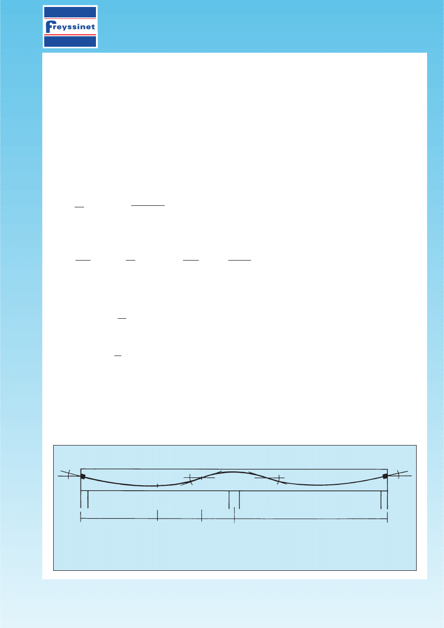
111.5 Example for calculation of the elongation of a prestressing tendon
The proposed example involves the tensioning of a prestressing unit consisting of 1 770 MPa class strands,
15.2 mm in diameter. This unit is threaded into a corrugated sheath, in a beam with two continuous spans,
each being 22.00 m long. The tendon layout is given by the following figure.
PPC
111/
1-
02.95
PAGE 15/16
Prestressing tendon in a beam with two symmetrical spans
In P
1
:
a
x1
= 8° X
1
= 12 m In P
2
:
a
x2
= 23° X
2
= 17 m In P
3
:
a
x3
= 38° X
3
= 22 m
P
0
P
3
P
1
P
2
P’
2
P’
1
a
1
= 15°
a
0
= 8°
a’
1
= 15°
a’
0
= 8°
P’
0
12,0
5,0
5,0
22,0

111. CALCULATION OF THE PRESTRESSING FORCE
PPC
111/
1-
02.95
PAGE 16/16
The tensioning is simultaneously carried out from both ends; the initial tension P
0
(or P’
0
) under the ancho-
rage, as calculated by the design office, is:
s
po
= 1 416 MPa.
– F
RICTION LOSSES DURING TENSIONING
(
SEE SECTION
111)
f = 0.18
w = 0.002, with: 1° = p : 180 = 0.01745 rad.
P
0
P
1
P
2
P
3
x (in m)
0
12.0
17.0
22.0
a (in rad)
0
0.1396
0.40135
0.6631
f
a + wx
0
0.04902
0.106243
0.163358
e
–(f
a + wx)
1
0.95216
0.89920
0.84928
s
p(x)
(in MPa)
1 416
1 348
1 273
1 202
– A
VERAGE TENSION IN EACH SECTION
P
0
/P
1
= (1 416 + 1 348) / 2 = 1 382 MPa ;
P
1
/P
2
= (1 348 + 1 273) / 2 = 1 310.5 MPa ;
P
2
/P
3
= (1 273 + 1 202) / 2 = 1 237.5 MPa.
– E
LONGATION IN EACH SECTION
P
0
/P
1
=
Dl
1
= (1 382 x 12 000) / 190 000 = 87.28 mm ;
P
1
/P
2
=
Dl
2
= (1 310.5 x 5 000) / 190 000 = 34.48 mm ;
P
2
/P
3
=
Dl
3
= (1 237.5 x 5 000) / 190 000 = 32.56 mm.
– T
OTAL ELONGATION BETWEEN
P
0 AND
P’
0
Dl = 2 x (Dl
1
+
Dl
2
+
Dl
3
) = 308.64 mm
≈
309 mm.
Note : When checking the tendon elongations at the jack, one must add the elongation corresponding to
the overlength of the strand outside the sheath, necessary for tensioning the tendon (distance between the an-
chorage and the jaws of the jack).
Wyszukiwarka
Podobne podstrony:
Lab 05 Obliczenia w C id 257534 Nieznany
Algorytmy obliczen id 57749 Nieznany
Oblicz (2) id 327340 Nieznany
Obliczenie siły krytycznej metodą energetyczną
platew obliczenia id 343774 Nieznany
obliczenia wytrzymalosciowe id Nieznany
OBLICZENIA ZAPOTRZEBOWANIA CIEP Nieznany
111 ZADANIA2 1 id 601077 Nieznany (2)
Prawdziwe oblicze zydostwa id 3 Nieznany
Obliczenia id 399360 Nieznany
OI14 Wyznaczanie sily elektromo Nieznany
11 Obliczenie Konstrukcji Z Uwz Nieznany (2)
11 OBLICZENIA KALKULACJEid 1252 Nieznany (2)
104 111 Podstawowe parametry wa Nieznany (2)
Budowa jadra atomowego, sily ja Nieznany (2)
MechTeor wyk 6 sily wewnetrzne Nieznany
102 111 ROZ w spr warunkow Nieznany (2)
więcej podobnych podstron