
Reference number
ISO 128-34:2001(E)
©
ISO 2001
INTERNATIONAL
STANDARD
ISO
128-34
First edition
2001-01-15
Technical drawings — General principles of
presentation —
Part 34:
Views on mechanical engineering drawings
Dessins techniques — Principes généraux de représentation —
Partie 34: Vues applicables aux dessins industriels
SIS-2002-574
2001

ISO 128-34:2001(E)
PDF disclaimer
This PDF file may contain embedded typefaces. In accordance with Adobe's licensing policy, this file may be printed or viewed but shall not
be edited unless the typefaces which are embedded are licensed to and installed on the computer performing the editing. In downloading this
file, parties accept therein the responsibility of not infringing Adobe's licensing policy. The ISO Central Secretariat accepts no liability in this
area.
Adobe is a trademark of Adobe Systems Incorporated.
Details of the software products used to create this PDF file can be found in the General Info relative to the file; the PDF-creation parameters
were optimized for printing. Every care has been taken to ensure that the file is suitable for use by ISO member bodies. In the unlikely event
that a problem relating to it is found, please inform the Central Secretariat at the address given below.
© ISO 2001
All rights reserved. Unless otherwise specified, no part of this publication may be reproduced or utilized in any form or by any means, electronic
or mechanical, including photocopying and microfilm, without permission in writing from either ISO at the address below or ISO's member body
in the country of the requester.
ISO copyright office
Case postale 56
·
CH-1211 Geneva 20
Tel. + 41 22 749 01 11
Fax + 41 22 749 09 47
E-mail copyright@iso.ch
Web www.iso.ch
Printed in Switzerland
ii
© ISO 2001 – All rights reserved

ISO 128-34:2001(E)
© ISO 2001 – All rights reserved
iii
Contents
Page
Foreword.....................................................................................................................................................................iv
1
Scope ..............................................................................................................................................................1
2
Normative references ....................................................................................................................................1
3
Terms and definitions ...................................................................................................................................1
4
Types of lines and their application.............................................................................................................2
5
Local views.....................................................................................................................................................2
6
Adjacent parts and contours ........................................................................................................................3
7
Intersections...................................................................................................................................................4
8
Square ends on shafts ..................................................................................................................................6
9
Interrupted views ...........................................................................................................................................6
10
Repeated features..........................................................................................................................................7
11
Enlarged features...........................................................................................................................................8
12
Initial outlines.................................................................................................................................................8
13
Bend lines.......................................................................................................................................................8
14
Slight inclines or curves ...............................................................................................................................9
15
Transparent objects ......................................................................................................................................9
16
Movable parts...............................................................................................................................................10
17
Finished parts and blanks ..........................................................................................................................11
18
Parts made from separate, equal elements ..............................................................................................11
19
Surface pattern.............................................................................................................................................12
20
Fibre and rolled directions..........................................................................................................................12
21
Parts with two or more identical views .....................................................................................................12
22
Mirror-image parts .......................................................................................................................................13

ISO 128-34:2001(E)
iv
© ISO 2001 – All rights reserved
Foreword
ISO (the International Organization for Standardization) is a worldwide federation of national standards bodies (ISO
member bodies). The work of preparing International Standards is normally carried out through ISO technical
committees. Each member body interested in a subject for which a technical committee has been established has
the right to be represented on that committee. International organizations, governmental and non-governmental, in
liaison with ISO, also take part in the work. ISO collaborates closely with the International Electrotechnical
Commission (IEC) on all matters of electrotechnical standardization.
International Standards are drafted in accordance with the rules given in the ISO/IEC Directives, Part 3.
Draft International Standards adopted by the technical committees are circulated to the member bodies for voting.
Publication as an International Standard requires approval by at least 75 % of the member bodies casting a vote.
Attention is drawn to the possibility that some of the elements of this part of ISO 128 may be the subject of patent
rights. ISO shall not be held responsible for identifying any or all such patent rights.
International Standard ISO 128-34 was prepared by Technical Committee ISO/TC 10, Technical product
documentation, Subcommittee SC 6, Mechanical engineering documentation.
This first edition is based on ISO 128:1982, clause 5, and replaces the rules specified in that clause.
ISO 128 consists of the following parts, under the general title Technical drawings — General principles of
presentation:
¾
Part 1: Introduction and index
¾
Part 20: Basic conventions for lines
¾
Part 21: Preparation of lines by CAD systems
¾
Part 22: Basic conventions and applications for leader lines and reference lines
¾
Part 23: Lines on construction drawings
¾
Part 24: Lines on mechanical engineering drawings
¾
Part 25: Lines on shipbuilding drawings
¾
Part 30: Basic conventions for views
¾
Part 34: Views on mechanical engineering drawings
¾
Part 40: Basic conventions for cuts and sections
¾
Part 44: Sections on mechanical engineering drawings
¾
Part 50: Basic conventions for representing areas on cuts and sections

INTERNATIONAL STANDARD
ISO 128-34:2001(E)
© ISO 2001 – All rights reserved
1
Technical drawings — General principles of presentation —
Part 34:
Views on mechanical engineering drawings
1
Scope
This part of ISO 128 specifies rules for the presentation of views additional to those of ISO 128-30 and applicable
to mechanical engineering drawings that follow the orthographic projection methods specified in ISO 5456-2.
Attention has also been given to reproduction requirements, including those of microcopying according to
ISO 6428.
2
Normative references
The following normative documents contain provisions which, through reference in this text, constitute provisions of
this part of ISO 128. For dated references, subsequent amendments to, or revisions of, any of these publications
do not apply. However, parties to agreements based on this part of ISO 128 are encouraged to investigate the
possibility of applying the most recent editions of the normative documents indicated below. For undated
references, the latest edition of the normative document referred to applies. Members of ISO and IEC maintain
registers of currently valid International Standards.
ISO 128-20:1996, Technical drawings — General principles of presentation — Part 20: Basic conventions for lines.
ISO 128-24:1999, Technical drawings — General principles of presentation — Part 24: Lines on mechanical
engineering drawings.
ISO 128-30:—
1
, Technical drawings — General principles of presentation — Part 30: Basic conventions for views.
ISO 129-1:—
2)
, Technical drawings — Indication of dimensions and tolerances — Part 1: General principles.
ISO 5456-2:1996, Technical drawings — Projection methods — Part 2: Orthographic representations.
ISO 6428:1982, Technical drawings — Requirements for microcopying.
ISO 10209-1:1992, Technical product documentation — Vocabulary — Part 1: Terms relating to technical
drawings: general and types of drawings.
3
Terms and definitions
For the purposes of this part of ISO 128, the terms and definitions given in ISO 10209-1 apply.
1
To be published.
2)
To be published. (Revision of ISO 129:1985)
ISO 128-34:2001(E)
2
© ISO 2001 – All rights reserved
4
Types of lines and their application
The basic types of lines referred to in this part of ISO 128 are specified in ISO 128-20. General rules and basic
conventions for their application on mechanical engineering drawings are specified in ISO 128-24.
5
Local views
Provided presentation is unambiguous, a local rather than a complete view of symmetrical parts is permitted. Local
views should be drawn in third angle projection, regardless of the arrangement used for the general execution of
the drawing. Local views shall be drawn with continuous wide lines (type 01.2) and connected to principal views by
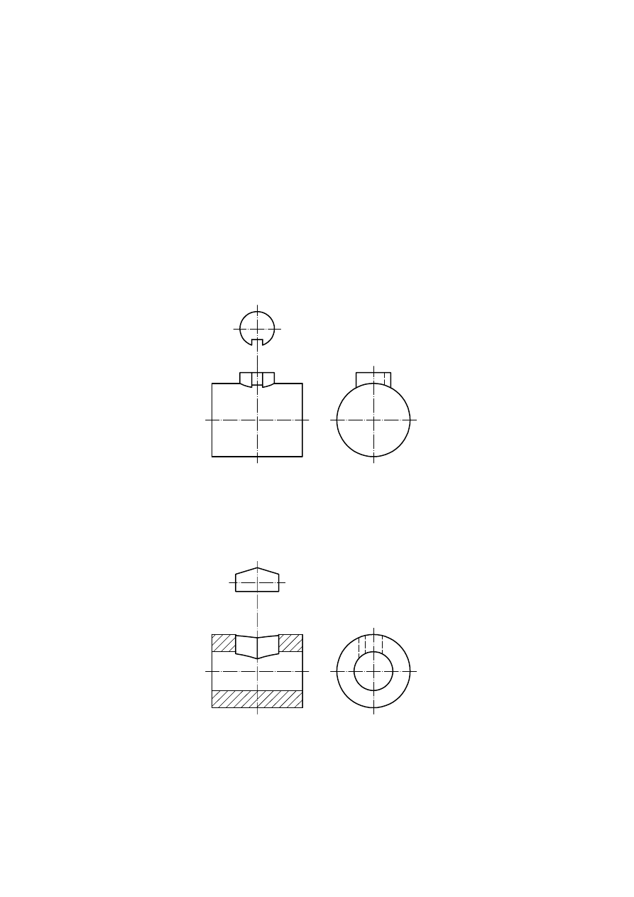
long dashed dotted narrow lines (type 04.1). Examples are shown in Figures 1 to 4.
Figure 1 — Local view of journal
Figure 2 — Local view of groove
ISO 128-34:2001(E)
© ISO 2001 – All rights reserved
3
Figure 3 — Local view of hole
Figure 4 — Local view of groove
6
Adjacent parts and contours
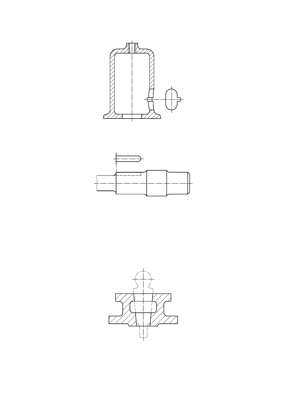
Where parts adjacent to an object are presented, they shall be drawn with long dashed double-dotted narrow lines
(type 05.1). The adjacent part shall not hide the principal part, but may be hidden by it (see Figure 5 and Figure 6).
Adjacent parts in cuts and sections shall not be hatched.
Figure 5 — Bounded adjacent part
ISO 128-34:2001(E)
4
© ISO 2001 – All rights reserved
Figure 6 — Adjacent parts
When the contours of features cannot or may not be definitively delineated, the area presumed to enclose them
shall be indicated by long dashed double-dotted narrow lines (type 05.1), as in Figure 7 and Figure 8.
a
Label for information.
Figure 7 — Indication of contours
Figure 8 — Indication of contours
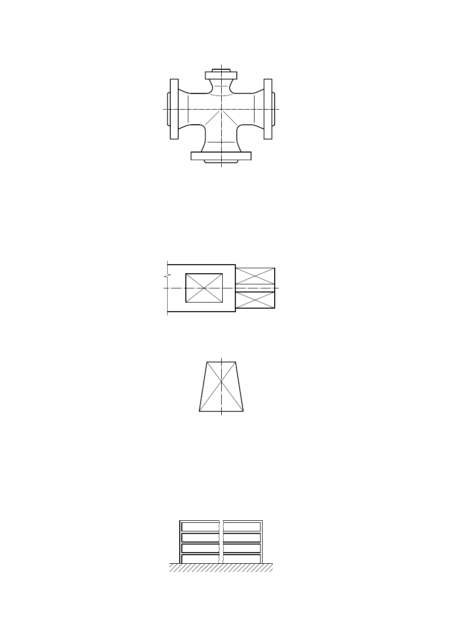
7
Intersections
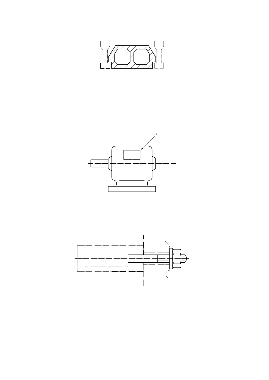
True geometric intersection lines shall be drawn with continuous wide lines (type 01.2) when visible, and with
dashed narrow lines (type 02.1) when hidden (see Figure 9).
ISO 128-34:2001(E)
© ISO 2001 – All rights reserved
5
Figure 9 — True intersection
Simplified representations of true geometric intersection lines may be applied at intersections, as follows.
¾
Between two cylinders the curved lines of intersection may be replaced by straight continuous wide lines
(see Figure 10).
¾
Between a cylinder and a rectangular prism the displacement of the straight line of intersection may be omitted
(see Figure 2).
However, the simplified representation should be avoided if it affects the intelligibility of the drawing.
Figure 10 — Simplified intersection
Imaginary intersection lines, such as fillets or rounded corners, shall be indicated in a view by continuous narrow
lines (type 01.1) that do not touch the outlines (see Figure 11).
ISO 128-34:2001(E)
6
© ISO 2001 – All rights reserved
Figure 11 — Imaginary intersections
8
Square ends on shafts
In order to avoid drawing a supplementary view, cut or section, square ends or flats (Figure 12), or tapered square
ends on shafts (Figure 13), shall be indicated by diagonals drawn as continuous narrow lines (type 01.1).
Figure 12 — Square end and flat
Figure 13 — Tapered square end
9
Interrupted views
In order to save space, it is permissible to show only those portions of a long object needed for its definition. The
limits of the parts retained shall be drawn as narrow, freehand or zigzag continuous lines. The portions shall be
drawn close to each other (see Figure 14 and Figure 15).
NOTE
Interrupted views do not show the true geometry.
Figure 14 — Interrupted view
ISO 128-34:2001(E)
© ISO 2001 – All rights reserved
7
Figure 15 — Interrupted view
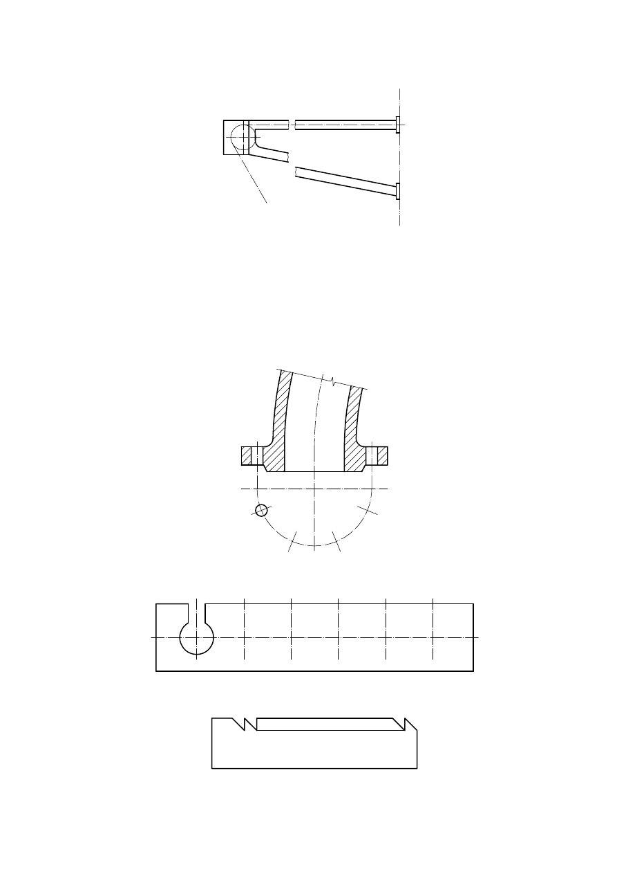
10 Repeated features
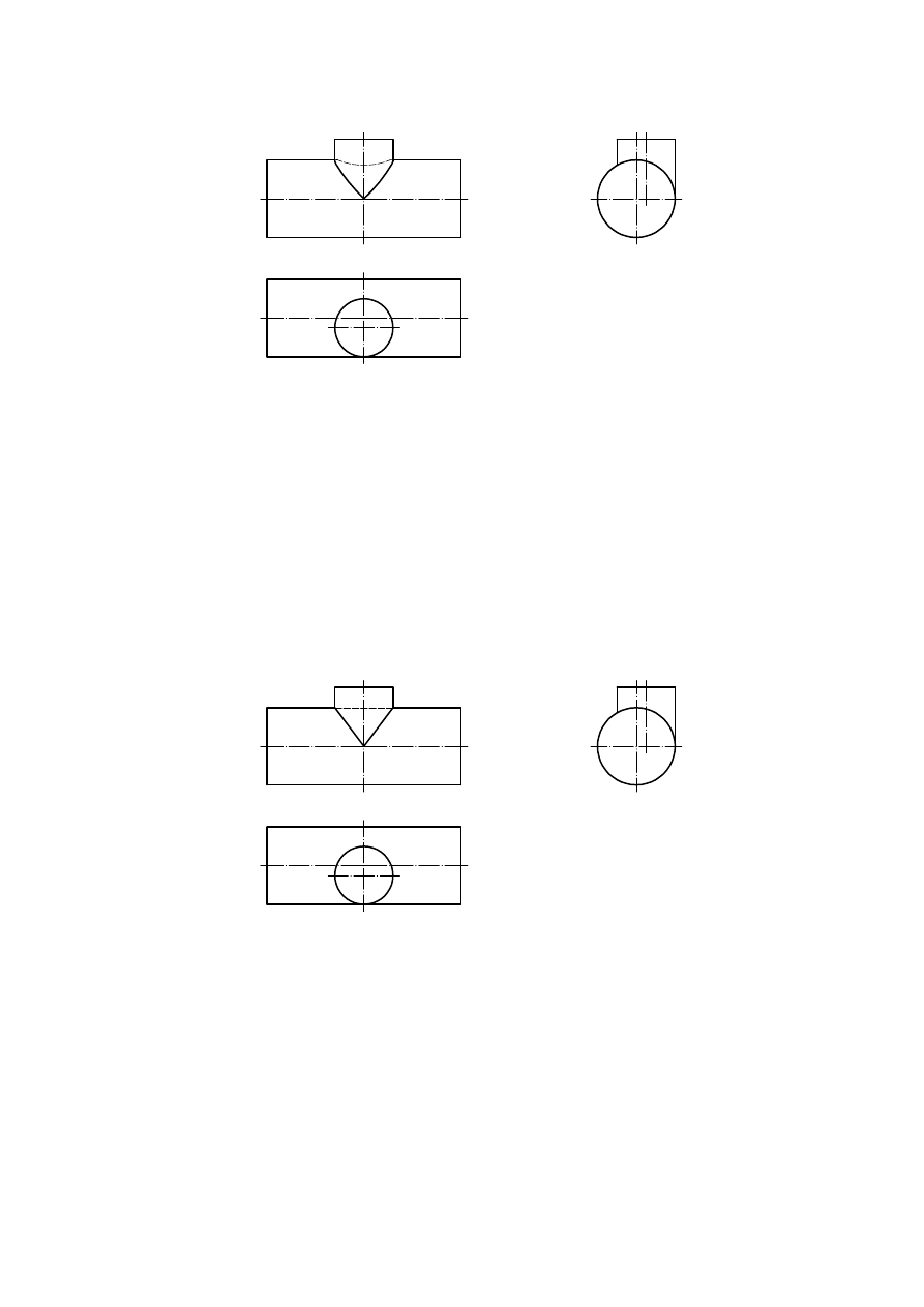
If certain identical features occur in a regular order, only one of them and their locations need be illustrated. In all
cases, the number and kind of repetitive features shall be defined by dimensioning according to ISO 129-1.
For symmetrical features, the location of the non-represented features is shown by long dashed dotted narrow lines
(type 04.1), as in Figure 16 and Figure 17. For asymmetrical features, the area of the non-represented features is
identified by continuous narrow lines (type 01.1) as shown in Figure 18.
Figure 16 — Symmetrical repeated features
Figure 17 — Symmetrical repeated features
Figure 18 — Asymmetrical repeated features
ISO 128-34:2001(E)
8
© ISO 2001 – All rights reserved
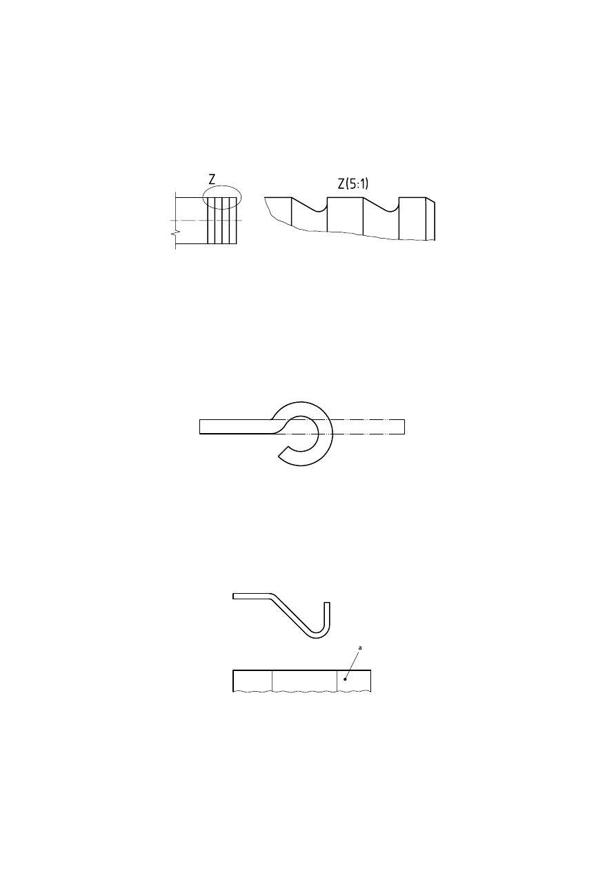
11 Enlarged features
When the scale of a drawing does not allow all features to be clearly shown or dimensioned, the unclear features
shall be enclosed or encircled by a continuous narrow line (type 01.1), with the area thus enclosed identified by a
capital letter. The features in the area shall also be shown on an enlarged scale, accompanied by the identification
letter and an indication of the scale beside it between parentheses, as shown in Figure 19.
Figure 19 — Enlarged features
12 Initial outlines
When it is necessary to depict initial outlines of a part prior to forming, these shall be indicated by long dashed
double-dotted narrow lines (type 05.1), as shown in Figure 20.
Figure 20 — Initial outlines
13 Bend lines
Bend lines in developed views shall be represented by continuous narrow lines (type 01.1), as shown in Figure 21.
a
Developed view.
Figure 21 — Bend lines
ISO 128-34:2001(E)
© ISO 2001 – All rights reserved
9
14 Slight inclines or curves
If slight inclines or curves (on angled surfaces, tapers, pyramids) are too slight to be clearly indicated in a
projection, their representation may be dispensed with. In such cases, only the edge corresponding to the
projection of the smaller dimension shall be drawn as a continuous wide line (type 01.2). This is indicated by the
projection lines in Figure 22 and Figure 23, which are drawn by way of explanation only.
Figure 22 — Slight curve
Figure 23 — Slight incline
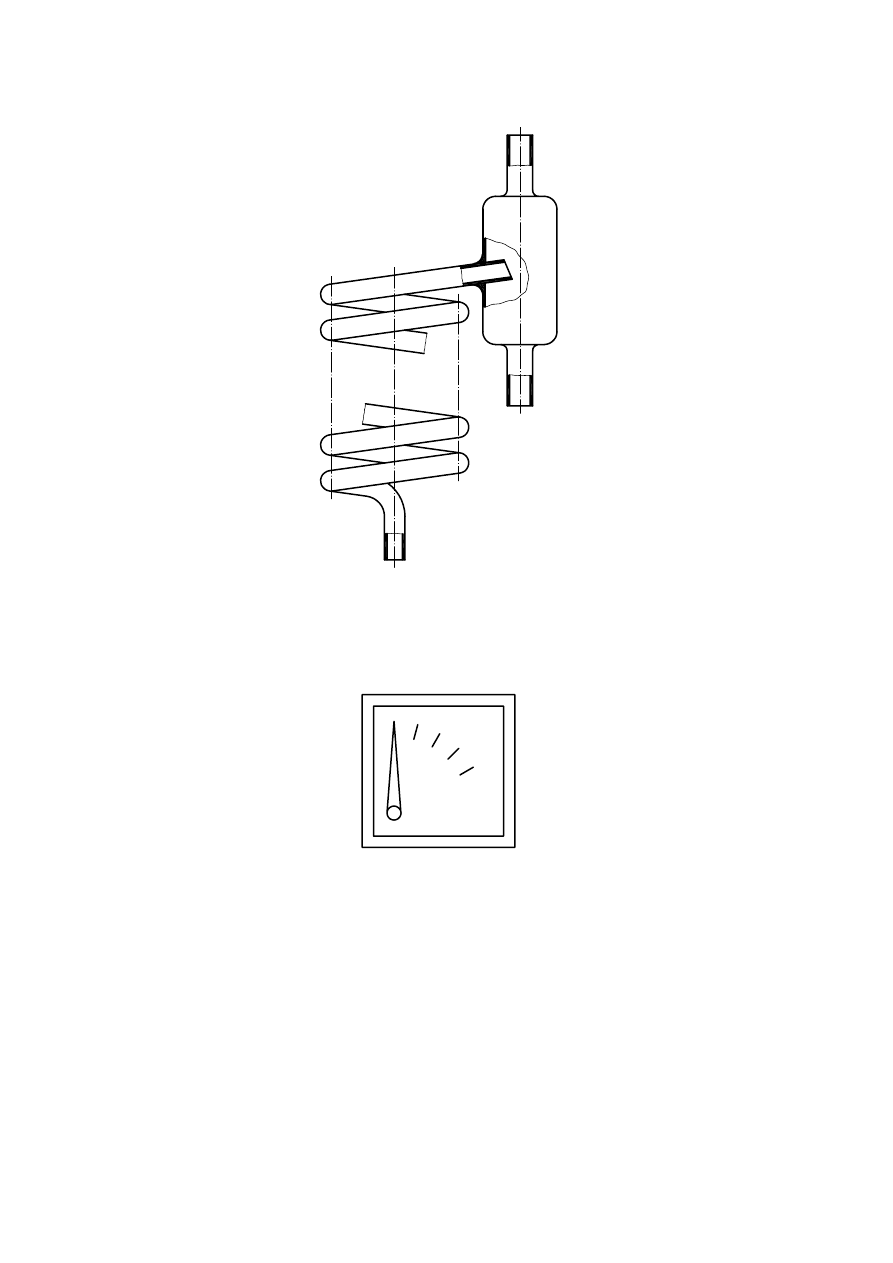
15 Transparent objects
All objects made of transparent material shall be drawn as if not transparent (see Figure 24).
Within assembly and general-assembly drawings, parts behind transparent parts may be drawn visible (see
Figure 25).
ISO 128-34:2001(E)
10
© ISO 2001 – All rights reserved
Figure 24 — Transparent object
Figure 25 — Assembly of transparent object
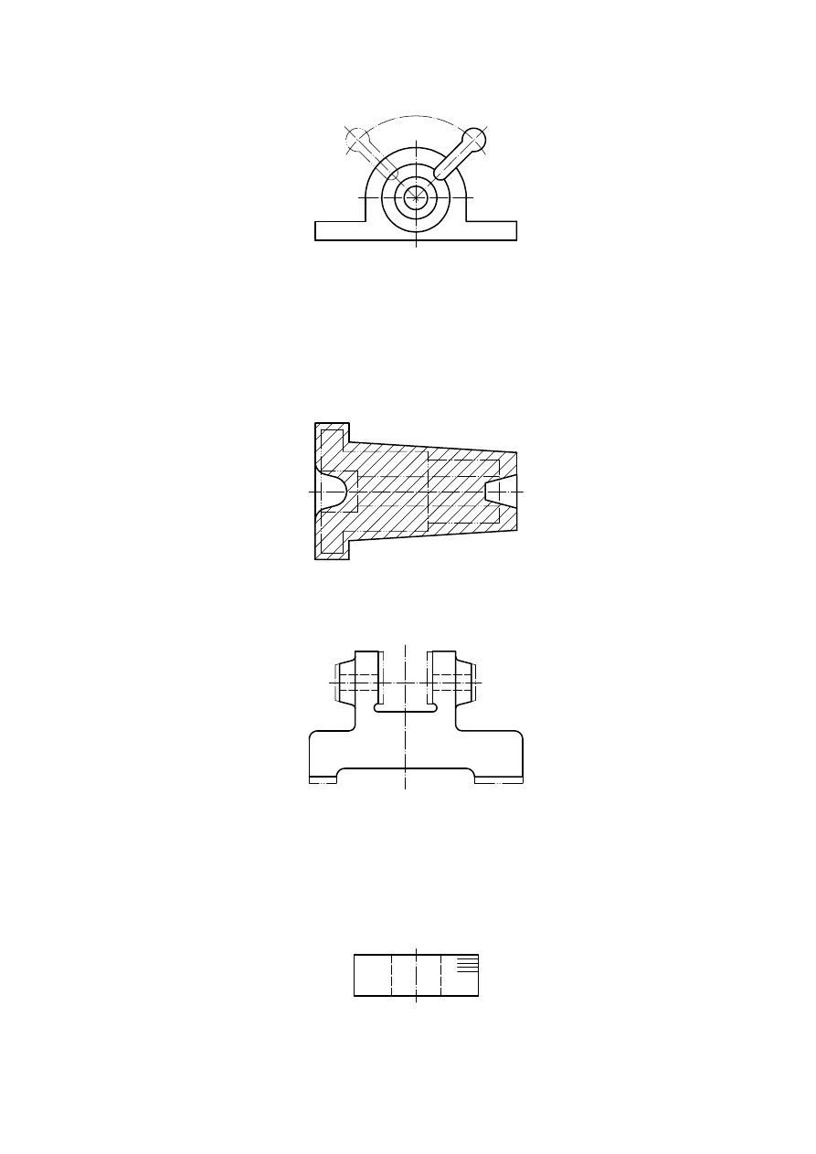
16 Movable parts
In assembly drawings the alternative and extreme positions of movable parts may be shown, drawn with long
dashed double-dotted narrow lines (type 05.1), as in Figure 26.
ISO 128-34:2001(E)
© ISO 2001 – All rights reserved
11
Figure 26 — Movable part
17 Finished parts and blanks
It is permitted to show the shape of a finished part within the drawing of a blank, or the shape of the blank within
the drawing of a finished part. These parts shall be drawn using long dashed double-dotted narrow lines (type 05.1)
(see Figure 27 and Figure 28).
Figure 27 — Finished part indicated in blank
Figure 28 — Blank indicated in finished part
18 Parts made from separate, equal elements
Parts made from separate, but equal, elements should be represented as homogeneous. The location of the
elements may be indicated by short continuous narrow (type 01.1) lines, as shown in Figure 29.
Figure 29 — Separate, equal elements
ISO 128-34:2001(E)
12
© ISO 2001 – All rights reserved
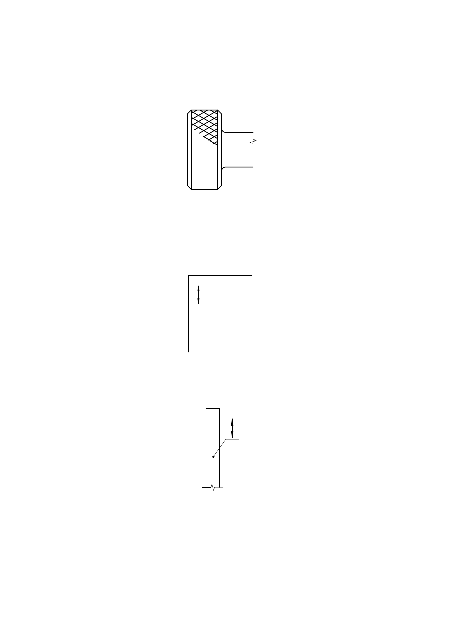
19 Surface pattern
The structure of knurling, corrugation, fluting, mesh or lattice shall be represented completely or partly by
continuous wide lines (type 01.2) (see Figure 30).
Figure 30 — Surface pattern
20 Fibre and rolled directions
The fibre and rolled directions need not be shown in the representation of a part, but if necessary may be indicated
by short continuous narrow (type 01.1) lines with arrowheads, as illustrated in Figure 31 and Figure 32.
Figure 31 — Fibre direction
Figure 32 — Rolled direction
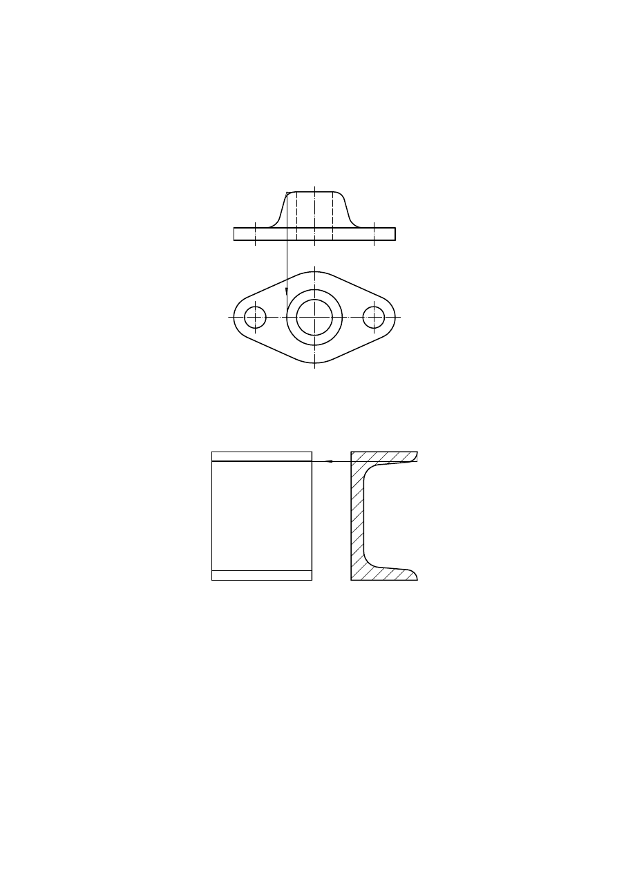
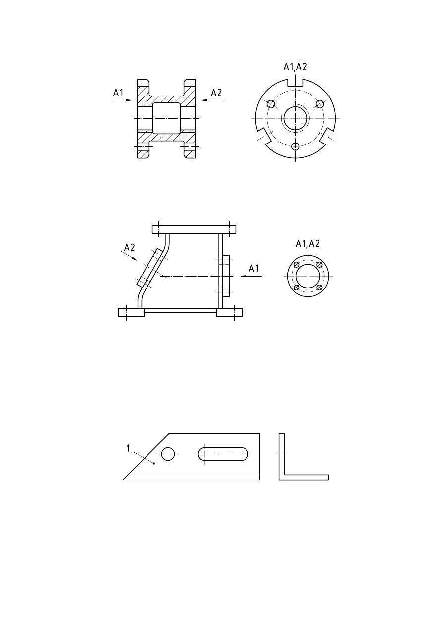
21 Parts with two or more identical views
Two or more equal views on any one part may be identified by the indication, “symmetrical part” (see ISO 128-30)
or by reference arrows and capital letters or numerals, or both, as in Figure 33 and Figure 34.
ISO 128-34:2001(E)
© ISO 2001 – All rights reserved
13
Figure 33 — Two identical views
Figure 34 — Two identical local views
22 Mirror-image parts
When simple parts are identical mirror images, a single representation shall suffice for both, provided that no errors
can arise in manufacture as a result. An explanatory note shall be placed near the title block. See Figure 35.
If necessary, simplified representations of the two parts drawn on a reduced scale without dimensioning may be
provided for emphasis.
Key
1
Part 1
EXAMPLE
(In title block) “Part 1, as drawn; part 2, identical mirror image.”
Figure 35 — Mirror-image parts

ISO 128-34:2001(E)
ICS 01.100.20
Price based on 13 pages
© ISO 2001 – All rights reserved
Wyszukiwarka
Podobne podstrony:
ISO128 24 lines mechanical
ISO128 30 views principles
ISO128 44 sections mechanical
ISO128 24 lines mechanical
Mechanika - Dynamika, cwiczeniadynamika10, Ćwiczenia 10
34. Mechanizm przepływu prądu elektrycznego, Fizyka - Lekcje
Części maszyn 34 - 38 Obróbka skrawaniem, mechanika, czesci maszyn
X 34 Badanie drgań wahadła, Weterynaria Lublin, Biofizyka , fizyka - od Bejcy, Mechanika
Human Rights, Bodies and Mechanisms, Forum on Minority Issues, United Nations Documents AHRC6L 34, 2
Mechanika techniczna(12)
Mechanika Semest I pytania egz
wykl 8 Mechanizmy
34 BAGNA, TORFOWISKA
34 Zasady projektowania strefy wjazdowej do wsi
więcej podobnych podstron