
MANUAL No. :
H740PB0091E
Serial No. :
Before using this machine and equipment, fully understand the contents of this
manual to ensure proper operation. Should any questions arise, please ask the
nearest Technical Center or Technology Center.
1. Be sure to observe the safety precautions described in this manual and the contents of the
safety plates on the machine and equipment. Failure may cause serious personal injury or
material damage. Please replace any missing safety plates as soon as possible.
2. No modifications are to be performed that will affect operation safety. If such modifications are
required, please contact the nearest Technical Center or Technology Center.
3. For the purpose of explaining the operation of the machine and equipment, some illustrations
may not include safety features such as covers, doors, etc. Before operation, make sure all
such items are in place.
4. This manual was considered complete and accurate at the time of publication, however, due to
our desire to constantly improve the quality and specification of all our products, it is subject to
change or modification. If you have any questions, please contact the nearest Technical Center
or Technology Center.
5. Always keep this manual near the machinery for immediate use.
6. If a new manual is required, please order from the nearest Technical Center or Technology
Center with the manual No. or the machine name, serial No. and manual name.
Issued by Manual Publication Section, Yamazaki Mazak Corporation, Japan
09. 2006
PROGRAMMING MANUAL
for
MAZATROL MATRIX
(for INTEGREX
IV series)
On the Use of Programs
Created with the M640MT Pro
IMPORTANT NOTICE

SAFETY PRECAUTIONS
S-1
SAFETY PRECAUTIONS
Preface
Safety precautions relating to the CNC unit (in the remainder of this manual, referred to simply as
the NC unit) that is provided in this machine are explained below. Not only the persons who
create programs, but also those who operate the machine must thoroughly understand the
contents of this manual to ensure safe operation of the machine.
Read all these safety precautions, even if your NC model does not have the corresponding
functions or optional units and a part of the precautions do not apply.
Rule
1. This section contains the precautions to be observed as to the working methods and states
usually expected. Of course, however, unexpected operations and/or unexpected working
states may take place at the user site.
During daily operation of the machine, therefore, the user must pay extra careful attention to
its own working safety as well as to observe the precautions described below.
2. Although this manual contains as great an amount of information as it can, since it is not
rare for the user to perform the operations that overstep the manufacturer-assumed ones,
not all of “what the user cannot perform” or “what the user must not perform” can be fully
covered in this manual with all such operations taken into consideration beforehand.
It is to be understood, therefore, that functions not clearly written as “executable” are
“inexecutable” functions.
3. The meanings of our safety precautions to DANGER, WARNING, and CAUTION are as
follows:
DANGER
: Failure to follow these instructions could result in loss of life.
WARNING
: Failure to observe these instructions could result in serious harm to a human
life or body.
CAUTION
: Failure to observe these instructions could result in minor injuries or serious
machine damage.
HGENPA0043E
SAFETY PRECAUTIONS
S-2
Basics
WARNING
! After turning power on, keep hands away from the keys, buttons, or switches of the
operating panel until an initial display has been made.
! Before proceeding to the next operations, fully check that correct data has been entered
and/or set. If the operator performs operations without being aware of data errors,
unexpected operation of the machine will result.
! Before machining workpieces, perform operational tests and make sure that the machine
operates correctly. No workpieces must be machined without confirmation of normal
operation. Closely check the accuracy of programs by executing override, single-block, and
other functions or by operating the machine at no load. Also, fully utilize tool path check,
Virtual Machining, and other functions, if provided.
! Make sure that the appropriate feed rate and rotational speed are designated for the
particular machining requirements. Always understand that since the maximum usable feed
rate and rotational speed are determined by the specifications of the tool to be used, those
of the workpiece to be machined, and various other factors, actual capabilities differ from
the machine specifications listed in this manual. If an inappropriate feed rate or rotational
speed is designated, the workpiece or the tool may abruptly move out from the machine.
! Before executing correction functions, fully check that the direction and amount of
correction are correct. Unexpected operation of the machine will result if a correction
function is executed without its thorough understanding.
! Parameters are set to the optimum standard machining conditions prior to shipping of the
machine from the factory. In principle, these settings should not be modified. If it becomes
absolutely necessary to modify the settings, perform modifications only after thoroughly
understanding the functions of the corresponding parameters. Modifications usually affect
any program. Unexpected operation of the machine will result if the settings are modified
without a thorough understanding.
Remarks on the cutting conditions recommended by the NC
WARNING
! Before using the following cutting conditions:
- Cutting conditions that are the result of the MAZATROL Automatic Cutting Conditions
Determination Function
- Cutting conditions suggested by the Machining Navigation Function
- Cutting conditions for tools that are suggested to be used by the Machining Navigation
Function
Confirm that every necessary precaution in regards to safe machine setup has been taken –
especially for workpiece fixturing/clamping and tool setup.
! Confirm that the machine door is securely closed before starting machining.
Failure to confirm safe machine setup may result in serious injury or death.
SAFETY PRECAUTIONS
S-3
Programming
WARNING
! Fully check that the settings of the coordinate systems are correct. Even if the designated
program data is correct, errors in the system settings may cause the machine to operate in
unexpected places and the workpiece to abruptly move out from the machine in the event
of contact with the tool.
! During surface velocity hold control, as the current workpiece coordinates of the surface
velocity hold control axes approach zeroes, the spindle speed increases significantly. For
the lathe, the workpiece may even come off if the chucking force decreases. Safety speed
limits must therefore be observed when designating spindle speeds.
! Even after inch/metric system selection, the units of the programs, tool information, or
parameters that have been registered until that time are not converted. Fully check these
data units before operating the machine. If the machine is operated without checks being
performed, even existing correct programs may cause the machine to operate differently
from the way it did before.
! If a program is executed that includes the absolute data commands and relative data
commands taken in the reverse of their original meaning, totally unexpected operation of
the machine will result. Recheck the command scheme before executing programs.
! If an incorrect plane selection command is issued for a machine action such as arc
interpolation or fixed-cycle machining, the tool may collide with the workpiece or part of the
machine since the motions of the control axes assumed and those of actual ones will be
interchanged. (This precaution applies only to NC units provided with EIA functions.)
! The mirror image, if made valid, changes subsequent machine actions significantly. Use
the mirror image function only after thoroughly understanding the above. (This precaution
applies only to NC units provided with EIA functions.)
! If machine coordinate system commands or reference position returning commands are
issued with a correction function remaining made valid, correction may become invalid
temporarily. If this is not thoroughly understood, the machine may appear as if it would
operate against the expectations of the operator. Execute the above commands only after
making the corresponding correction function invalid. (This precaution applies only to NC
units provided with EIA functions.)
! The barrier function performs interference checks based on designated tool data. Enter the
tool information that matches the tools to be actually used. Otherwise, the barrier function
will not work correctly.
! The system of G-code and M-code commands differs, especially for turning, between the
machines of INTEGREX e-Series and the other turning machines.
Issuance of the wrong G-code or M-code command results in totally non-intended machine
operation. Thoroughly understand the system of G-code and M-code commands before
using this system.
Sample program
Machines of INTEGREX e-Series
Turning machines
S1000M3
The milling spindle rotates at 1000 min
–1
.
The turning spindle rotates at 1000 min
–1
.
S1000M203
The turning spindle rotates at 1000 min
–1
.
The milling spindle rotates at 1000 min
–1
.
SAFETY PRECAUTIONS
S-4
! For the machines of INTEGREX e-Series, programmed coordinates can be rotated using
an index unit of the MAZATROL program and a G68 command (coordinate rotate com-
mand) of the EIA program. However, for example, when the B-axis is rotated through 180
degrees around the Y-axis to implement machining with the turning spindle No. 2, the plus
side of the X-axis in the programmed coordinate system faces downward and if the
program is created ignoring this fact, the resulting movement of the tool to unexpected
positions may incite collisions.
To create the program with the plus side of the X-axis oriented in an upward direction, use
the mirror function of the WPC shift unit or the mirror imaging function of G-code command
(G50.1, G51.1).
! After modifying the tool data specified in the program, be sure to perform the tool path
check function, the Virtual Machining function, and other functions, and confirm that the
program operates properly. The modification of tool data may cause even a field-proven
machining program to change in operational status.
If the user operates the machine without being aware of any changes in program status,
interference with the workpiece could arise from unexpected operation.
For example, if the cutting edge of the tool during the start of automatic operation is present
inside the clearance-including blank (unmachined workpiece) specified in the common unit
of the MAZATROL program, care is required since the tool will directly move from that
position to the approach point because of no obstructions being judged to be present on
this path.
For this reason, before starting automatic operation, make sure that the cutting edge of the
tool during the start of automatic operation is present outside the clearance-including
workpiece specified in the common unit of the MAZATROL program.
CAUTION
! If axis-by-axis independent positioning is selected and simultaneously rapid feed selected
for each axis, movements to the ending point will not usually become linear. Before using
these functions, therefore, make sure that no obstructions are present on the path.
! Before starting the machining operation, be sure to confirm all contents of the program
obtained by conversion. Imperfections in the program could lead to machine damage and
operator injury.
SAFETY PRECAUTIONS
S-5
Operations
WARNING
! Single-block, feed hold, and override functions can be made invalid using system variables
#3003 and #3004. Execution of this means the important modification that makes the
corresponding operations invalid. Before using these variables, therefore, give thorough
notification to related persons. Also, the operator must check the settings of the system
variables before starting the above operations.
! If manual intervention during automatic operation, machine locking, the mirror image
function, or other functions are executed, the workpiece coordinate systems will usually be
shifted. When making machine restart after manual intervention, machine locking, the
mirror image function, or other functions, consider the resulting amounts of shift and take
the appropriate measures. If operation is restarted without any appropriate measures being
taken, collision with the tool or workpiece may occur.
! Use the dry run function to check the machine for normal operation at no load. Since the
feed rate at this time becomes a dry run rate different from the program-designated feed
rate, the axes may move at a feed rate higher than the programmed value.
! After operation has been stopped temporarily and insertion, deletion, updating, or other
commands executed for the active program, unexpected operation of the machine may
result if that program is restarted. No such commands should, in principle, be issued for the
active program.
CAUTION
! During manual operation, fully check the directions and speeds of axial movement.
! For a machine that requires manual homing, perform manual homing operations after
turning power on. Since the software-controlled stroke limits will remain ineffective until
manual homing is completed, the machine will not stop even if it oversteps the limit area.
As a result, serious machine damage will result.
! Do not designate an incorrect pulse multiplier when performing manual pulse handle feed
operations. If the multiplier is set to 1000 times and the handle operated inadvertently, axial
movement will become faster than that expected.

BEFORE USING THE NC UNIT
S-6
BEFORE USING THE NC UNIT
Limited Warranty
The warranty of the manufacturer does not cover any trouble arising if the NC unit is used for its
non-intended purpose. Take notice of this when operating the unit.
Examples of the trouble arising if the NC unit is used for its non-intended purpose are listed
below.
1. Trouble associated with and caused by the use of any commercially available software
products (including user-created ones)
2. Trouble associated with and caused by the use of any Windows operating systems
3. Trouble associated with and caused by the use of any commercially available computer
equipment
Operating Environment
1. Ambient
temperature
During machine operation: 0° to 50°C (32° to 122°F)
2. Relative
humidity
During machine operation: 10 to 75% (without bedewing)
Note:
As humidity increases, insulation deteriorates causing electrical component parts to
deteriorate quickly.
Keeping the Backup Data
Note:
Do not attempt to delete or modify the data stored in the following folder.
Recovery Data Storage Folder: D:\MazakBackUp
Although this folder is not used when the NC unit is running normally, it contains important data
that enables the prompt recovery of the machine if it fails.
If this data has been deleted or modified, the NC unit may require a long recovery time. Be sure
not to modify or delete this data.
E

C-1
CONTENTS
Page
1
OUTLINE .............................................................................................. 1-1
2
DIFFERENCES IN MAZATROL PROGRAMS ..................................... 2-1
2-1
Outline ................................................................................................................2-1
2-2
Detailed Description ...........................................................................................2-1
3
MAZATROL PROGRAM CONVERSION FUNCTION .......................... 3-1
4
DIFFERENCES IN EIA/ISO PROGRAMS ............................................ 4-1
4-1
Outline ................................................................................................................4-1
4-2
Differences in G-Codes ......................................................................................4-1
4-3
Differences in M-Codes ......................................................................................4-6
4-4
Smallest Input Capacity......................................................................................4-8
5
INFORMATION FOR USERS WHO USE FLOPPY DISKS.................. 5-1
5-1
Outline ................................................................................................................5-1
5-2
Methods..............................................................................................................5-1

C-2
- NOTE -
E
OUTLINE
1
1-1
1 OUTLINE
The MAZATROL MATRIX is the Mazak’s latest model of rapid and highly accurate CNC unit with
new functions added to the conventional M640 series. Since the new functions are added, part of
the MAZATROL MATRIX differs from conventional CNC models in programming and in
operations.
This manual describes the following items for safer machine operations by the user:
No.
Item
Description
1
Differences in MAZATROL
programs
Describes the differences from the M640MT Pro in MAZATROL
programs.
2
MAZATROL program conversion
function
Describes the loading of the programs which have been created by the
M640 series, and the related precautions.
3
Differences in EIA/ISO programs
Sets forth the differences from the M640MT Pro in EIA/ISO programs.
4
Information for users who use
floppy disks
Describes the loading of the programs saved on a floppy disk through a
USB device into the MAZATROL MATRIX.
The users of the M640MT Pro are requested to confirm the differences in programming.
When programs that have been created by the M640 series are to be loaded into the
MAZATROL MATRIX, confirm the contents of the automatically converted programs before
running them actually on a machine.
CAUTION
! Before starting the machining operation, be sure to confirm all contents of the program
obtained by conversion. Imperfections in the program could lead to machine damage and
operator injury.

1
OUTLINE
1-2
- NOTE -
E

DIFFERENCES IN MAZATROL PROGRAMS
2
2-1
2
DIFFERENCES IN MAZATROL PROGRAMS
2-1 Outline
This chapter describes the differences in MAZATROL programs between the M640MT Pro and
the MAZATROL MATRIX. The differences are listed below.
No.
Item
Difference
1
Turning unit
The B-axis index angle that has formerly been set up in the TOOL DATA display can
be set up in the PROGRAM display. This allows the user to confirm program con-
tents in the flow of programming.
2
Attributes of starting
and ending points of a
line machining unit
For Line - Center, Line - Left, Line - Right, Chamfer - Right, and Chamfer - Left
machining units, the attributes of starting and ending points can be set up to prevent
excessive cutting and insufficient cutting.
3
Priority numbering
scheme
The method of determining the order of machining is changed from the conventional
process layout scheme to a priority numbering scheme so that the order of machin-
ing can be freely determined within a program once created.
4
Manual programming
unit
The number of available G-codes is increased to allow use of G-codes equivalent to
those for EIA/ISO programming.
5
Workpiece transfer unit
Transfer information can be set not only in the SETUP INFORMATION display, but
also in the PROGRAM display.
6
TPC relay points
As for Tool Path Control for milling units, radius/diameter selection can be done by
parameter setting for the entry of the X-coordinates of approach and escape relay
points.
7
Tool wear compen-
sation
Compensation of milling tools for wear is made valid for the axial direction of the tool.
Note:
Loading programs created with the M640MT Pro into the MAZATROL MATRIX is done
by automatic conversion into the format proper to the latter, indeed, but some items
may be left unset because of the above differences, and require manual setting. See
Chapter 3, MAZATROL PROGRAM CONVERSION FUNCTION, for further details.
2-2 Detailed
Description
1.
Turning unit
The item of the B-axis index angle is added to the turning unit. While for the M640MT Pro the B-
axis index angle is to be set up externally in the TOOL DATA display, it can now be set for the
MAZATROL MATRIX directly in the PROGRAM display.
2
DIFFERENCES IN MAZATROL PROGRAMS
2-2
A.
M640MT Pro
UNo.
1
UNIT
BAR
PART
OUT
CPT-X
80.
CPT-Z
0.
FIN-X
0.3
FIN-Z
0.1
SNo.
R 1
F 2
TOOL
GENERAL OUT
GENERAL OUT
NOM.
25. A
25. C
#
PAT.
0
!
DEP-1
2
!
DEP-2/NUM.
!
!
DEP-3
!
!
FIN-X
!
0.
FIN-Z
!
0.
C-SP
150
180
FR
0.4
0.2
M M
FIG
1
2
SHP
LIN
TPR
S-CNR
C 1.5
SPT-X
!
50.
SPT-Z
!
40.
FPT-X
50.
80.
FPT-Z
40.
70.
F-CNR/$
RADIUS/th
!
RGH
▼▼▼6
▼▼▼6
B.
MAZATROL MATRIX
UNo.
1
UNIT
BAR
PART
OUT
POS-B
90.
CPT-X
80.
CPT-Z
0.
FIN-X
0.3
FIN-Z
0.1
SNo.
R 1
F 2
TOOL
GENERAL OUT
GENERAL OUT
NOM.
25. A
25. C
No. #
1
2
PAT.
0
!
DEP-1
2
!
DEP-2/NUM.
!
!
DEP-3
!
!
FIN-X
!
0.
FIN-Z
!
0.
C-SP
150
180
FR
0.4
0.2
M M M
FIG
1
2
PTN
LIN
TPR
S-CNR
C 1.5
SPT-X
!
50.
SPT-Z
!
40.
FPT-X
50.
80.
FPT-Z
40.
70.
F-CNR/$
R/th
!
RGH
▼▼▼6
▼▼▼6
2.
Attributes of starting and ending points of a line machining unit
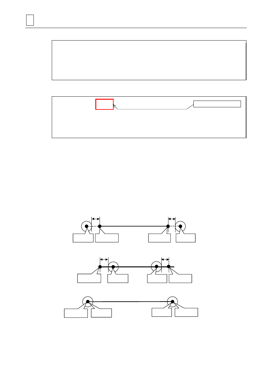
For line machining (milling by contouring control), the attributes of starting and ending points can
be set up in Line - Center, Line - Left, Line - Right, Chamfer - Right, and Chamfer - Left units.
This may cause the tool path in the TOOL PATH CHECK display to differ from that drawn by the
M640MT Pro. The tool path is determined by bit 3 of parameter E104. See Section 3-6, Line
Machining Units, of the PROGRAMMING MANUAL (MAZATROL) for more information.
Examples of the tool path for a Line - Center unit are shown below.
- E104 bit 3 = 0
Attribute: OPEN (the same tool path as when MT Pro parameter P3 bit 4 = 0)
E2
Cutting
start point
Shape’s
starting point
Shape’s
ending point
Cutting
end point
E2
Attribute: CLOSED
E30
Cutting
start point
Shape’s
starting point
Cutting
end point
Shape’s
ending point
E30
- E104 bit 3 = 1 (the same tool path as when MT Pro parameter P3 bit 4 = 1)
Cutting
start point
Shape’s
starting point
Cutting
end point
Shape’s
ending point
The starting (or ending) point of the shape and the starting (or ending) point of cutting agree,
irrespective of the attributes.
B-axis angle for machining
DIFFERENCES IN MAZATROL PROGRAMS
2
2-3
3.
Priority numbering scheme
The method of determining the order of machining is changed from the conventional process
layout scheme to a priority numbering scheme. The priority numbers can be set directly in the
PROGRAM display. See Chapter 4, PRIORITY FUNCTION FOR THE SAME TOOL, of the
PROGRAMMING MANUAL (MAZATROL) for more information.
A.
M640MT Pro
UNo.
1
UNIT
BAR
PART
OUT
CPT-X
80.
CPT-Z
0.
FIN-X
0.3
FIN-Z
0.1
SNo.
R 1
F 2
TOOL
GENERAL OUT
GENERAL OUT
NOM.
25. A
25. C
#
PAT.
0
!
DEP-1
2
!
DEP-2/NUM.
!
!
DEP-3
!
!
FIN-X
!
0.
FIN-Z
!
0.
C-SP
150
180
FR
0.4
0.2
M M
FIG
1
2
SHP
LIN
TPR
S-CNR
C 1.5
SPT-X
!
50.
SPT-Z
!
40.
FPT-X
50.
80.
FPT-Z
40.
70.
F-CNR/$
RADIUS/th
!
RGH
▼▼▼6
▼▼▼6
B.
MAZATROL MATRIX
UNo.
1
UNIT
BAR
PART
OUT
POS-B
90.
CPT-X
80.
CPT-Z
0.
FIN-X
0.3
FIN-Z
0.1
SNo.
R 1
F 2
TOOL
GENERAL OUT
GENERAL OUT
NOM.
25. A
25. C
No. #
1
2
PAT.
0
!
DEP-1
2
!
DEP-2/NUM.
!
!
DEP-3
!
!
FIN-X
!
0.
FIN-Z
!
0.
C-SP
150
180
FR
0.4
0.2
M M M
FIG
1
2
PTN
LIN
TPR
S-CNR
C 1.5
SPT-X
!
50.
SPT-Z
!
40.
FPT-X
50.
80.
FPT-Z
40.
70.
F-CNR/$
R/th
!
RGH
▼▼▼6
▼▼▼6
4.
Manual programming unit
While only seven types of G-codes can be used in a manual programming unit of the
M640MT Pro, the MAZATROL MATRIX allows general G-codes of EIA programming to be used.
See Section 3-18, Manual Program Machining Unit, of the PROGRAMMING MANUAL
(MAZATROL) as well as the PROGRAMMING MANUAL (EIA/ISO) for more information.
Note 1: Select a plane of circular interpolation before giving a G2/G3 command. If no plane is
determined beforehand, the XY-plane will be selected as a default setting.
Note 2: For milling as well as turning tools, tool wear compensation for manual programming
units can only occur along the axes of the rectangular coordinates of the machine.
Note 3: The manual programming unit does not allow incremental data input to be used for the
W-axis. To give a command of W-axis movement, specify absolute data with address B
as follows:
G110B2
G0B
xxx
G111
.
Machining priority number
2
DIFFERENCES IN MAZATROL PROGRAMS
2-4
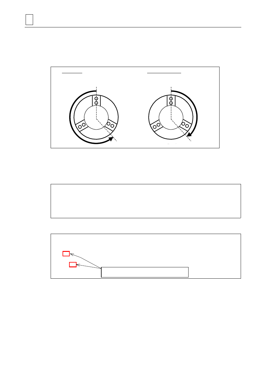
Note 4: While a G00 or G01 command given for the C-axis in a manual programming unit of the
M640MT Pro is always executed in the rotational direction according to the sign of the
specified numerical value, the MAZATROL MATRIX can execute such a command
through the shorter route. An example of operation is shown below.
Example:
G00C–220.
is given in a manual programming unit.
D740PB0015
M640MT Pro
Rotation in the negative direction
(as specified in the numerical value)
C = 0
–220
+140
C = 0
MAZATROL MATRIX
Rotation in the positive direction
(as for the shorter route)
Remark: For the above example, use the address H for incremental data input (as in
G00H-220.
) to forcibly obtain by the MAZATROL MATRIX a rotation in the
negative direction of the C-axis.
A.
M640MT Pro
UNo.
1
UNIT
MANUAL.P
CHANGE-PT
1
GEAR
1
TOOL
GENERAL OUT 80. A
#
SEQ
1
2
3
G
0
1
1
DATA-1
X
90.
Z –100.
X
102.
DATA-2
Z 5.
DATA-3
RADIUS/VARIABLE
!
!
!
RPM
V 120
FEED
REV 0.5
M
OFS
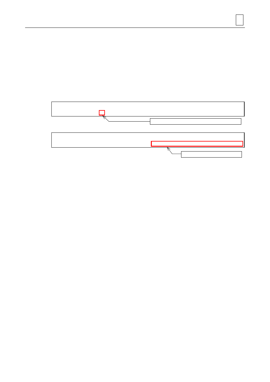
B.
MAZATROL MATRIX
UNo.
1
UNIT
MANL PRG
TOOL
GENERAL OUT
NOM-
φ
80. A
No.
#
POS-B
90.
SEQ
1
2
3
4
5
G1
96
0
1
1
G2
99
DATA-1
X
90.
Z –100.
X 102.
DATA-2
Z 5.
DATA-3
DATA-4
DATA-5
DATA-6
F 0.5
S
V 120
M/B
Explicit designation of G-codes: for constant cutting
speed (G96), and feed per revolution (G99)
DIFFERENCES IN MAZATROL PROGRAMS
2
2-5
5.
Workpiece transfer unit
Workpiece transfer information can be set up within a MAZATROL program of the MAZATROL
MATRIX. The transfer information can also be prepared in the SETUP INFORMATION display
similarly to the M640MT Pro. Transfer settings in the SETUP INFORMATION display are created
automatically from the data items specified in the MAZATROL program.
See Section 3-21, Workpiece Transfer Unit, of the PROGRAMMING MANUAL (MAZATROL) for
more information, as well as PART 3, Chapter 5, DISPLAYS RELATED TO MACHINING SETUP,
of the OPERATING MANUAL.
A.
M640MT Pro
UNo.
5
UNIT
TRANSFER CHK
SETUP-No.
1
HEAD
1->2
SPDL
4
PUSH
0
CHUCK
!
B.
MAZATROL MATRIX
UNo.
5
UNIT
TRANSFER
PAT.
CHUCK
HEAD
1->2
SPDL
4
PUSH
0
CHUCK
!
W1
-971.
W2
0.
Z-OFFSET
763.
C1
0.
C2
0.
C-OFFSET
0.
6.
TPC relay points
The entry of the X-coordinates of TPC approach and escape relay points is to be performed in
radius or diameter values for milling units according as bit 0 of parameter D105 is set to zero (0)
or one (1). Note that the entry in question must always be done in diameter values for turning
units. See Chapter 6, TPC DATA SETTING, of the PROGRAMMING MANUAL (MAZATROL) for
more information.
Number of reference to the Setup Information settings
Direct entry of transfer information
2
DIFFERENCES IN MAZATROL PROGRAMS
2-6
7.
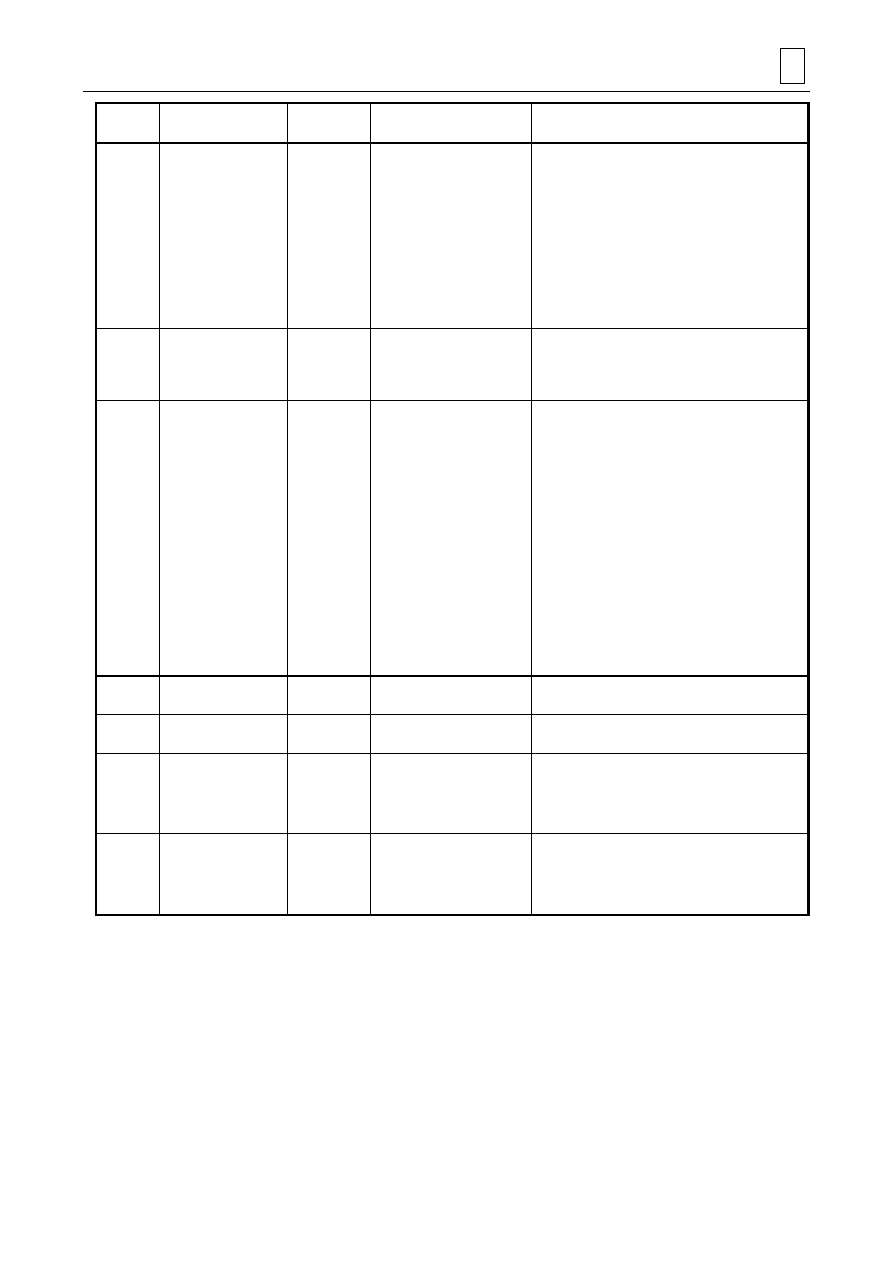
Tool wear compensation
Compensation of milling tools for wear is made valid for the axial direction of the tool. Wear
compensation is performed for turning and milling tools in the following directions:
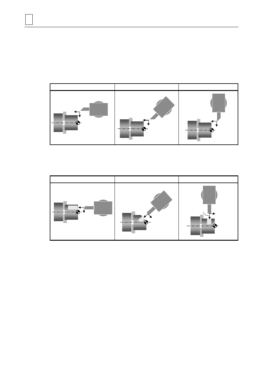
A.
For turning tools
Wear compensation for turning tools takes place in the longitudinal direction (Z) and radial
direction (X) of the workpiece, regardless of the B-axis index angle.
B = 0°
B = 45°
B = 90°
Comp. X
B = 0°
Comp. Z
Comp. X
Comp. Z
B = 45°
B = 90°
Comp. X
Comp. Z
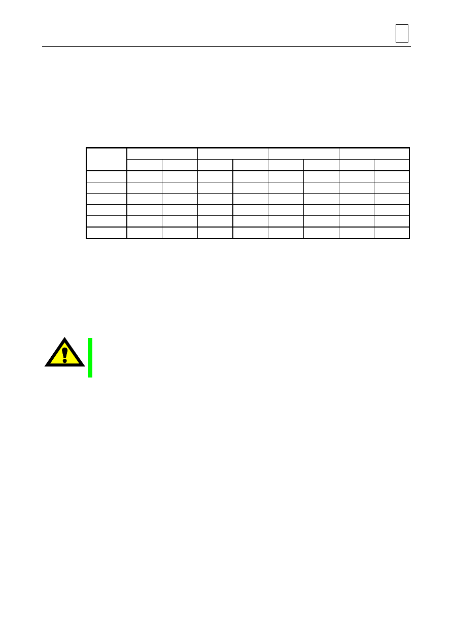
B.
For milling tools
Wear compensation for milling tools is performed with the radial direction of the tool taken as X,
and its axial direction taken as Z.
B = 0°
B = 45°
B = 90°
Comp. X
Comp. Z
B = 0°
Comp. X
Comp. Z
B = 45°
Comp. X
Comp. Z
B = 90°
E
MAZATROL PROGRAM CONVERSION FUNCTION
3
3-1
3
MAZATROL PROGRAM CONVERSION FUNCTION
1.
Outline
The MAZATROL program that has been created using the M640T/T NEXUS, M640MT,
M640M Pro or M640MT Pro can be converted into an appropriate format and then loaded into
the memory of the MAZATROL MATRIX. The input and output functions that can be used for the
conversion are as listed in the table below.
!: Convertible ×: Inconvertible
M640MT Pro
M640MT
M640T/T NEXUS
M640M Pro
Binary
Text
Binary
Text
Binary
Text
Binary
Text
CARD
!
!
!
!
!
!
!
!
HARD DISK
!
!
!
!
!
!
!
!
USB
!
!
!
!
!
!
!
!
FLOPPY
!
!
!
!
!
!
!
!
TAPE
—
!
—
!
—
!
—
!
CMT
!
—
!
—
!
—
!
—
Note:
After loading the MAZATROL program that has been created using another type of NC
unit, it is absolutely necessary to confirm the contents of the program and enter missing
data and data that has not been converted.
Remark: When a program created using an NC unit with an input sensitivity of micrometer
(0.001 mm) is loaded, some digital items may be displayed up to the fourth decimal
digit. Such items refer to values that have been set by the auto-setting function, and
can be used as they are since our NC unit has an input sensitivity of submicron
(0.0001 mm).
CAUTION
" Before starting the machining operation, be sure to confirm all contents of the program
obtained by conversion. Imperfections in the program could lead to machine damage and
operator injury.
2.
Restrictions
Loading programs created with the M640 series into the MAZATROL MATRIX is done by
automatic conversion into the format proper to the latter, indeed, but some items may be left
unset due to the following factors, and require manual setting.
- Setup data and barrier information
Setup data and barrier information prepared for the M640 series are excluded from the con-
version since the settings in question are to be re-set for the particular machine (as is the case
with Z-offset, C-offset and tailstock position data), to be specified internally in a MAZATROL
program (information on measurement interval and workpiece transfer), or absolutely unnec-
essary (barrier information).
- Process layout data
The method of determining the order of machining is changed from the conventional process
layout scheme to a priority numbering scheme, and priority number settings will be left unset
since the process layout data of the source programs prepared with the M640 series have no
information on the priority of tool usage.

3
MAZATROL PROGRAM CONVERSION FUNCTION
3-2
- TPC data
The TPC (Tool Path Control) data are used for the prevention of interference by a particular
control unit on a particular machine and must generally be re-set for another NC and another
machine. Therefore, TPC data are excluded from the conversion in question.
- Measurement unit
Units for measurement prepared with the M640 series are excluded from the conversion in
question since they do not contain necessary information for the advanced measurement
features (use of the Y-axis control, etc.).
- Manual programming unit
In the conversion of a manual program turning or milling unit of the M640 series into a
corresponding unit of the MAZATROL MATRIX without distinction between turning and milling,
dimensional information of incremental data input in the source unit is converted into
corresponding values of absolute data input. Every axis-movement value, however, in the
sequences of the converted unit will be left unset (blank) – in order to ensure operational safety
– if there is even only one dimensional value of incremental data input specified in the first
sequence of axis movement because no reliable conversion into values of absolute data input
can be obtained in such a case.
- Tool specifying method
In converting programs created by the M640 series in which the tools used are specified with
their numbers, the type and machining section for designating the necessary tools are
determined automatically with reference to the type and machining section of the source unit,
but the nominal size and suffix must be specified manually. Moreover, change the tool
information in a converted program as required for optimum machining conditions.
- Gear
Gear-shifting commands are excluded from the conversion in question since they must
generally be re-set for another machine according to the particular specifications of the spindle.
- Converting M640M Pro programs
As for programs prepared with the M640M Pro unit, only programs of workpiece scheme
(MILLING & TURN) can be converted appropriately.
MAZATROL PROGRAM CONVERSION FUNCTION
3
3-3
3.
Example of program conversion
Shown below is an example of the conversion conducted when a program created with the
M640MT Pro is loaded into the MAZATROL MATRIX. In this example, the B-axis angle needs to
be designated manually.
A.
M640MT Pro (Program before automatic conversion)
UNo.
0
MAT
CBN STL
OD-MAX
80.
ID-MIN
0.
LENGTH
100.
WORK FACE
0.
RPM
2000
TR2-DIA
200.
UNo.
1
UNIT
BAR
PART
OUT
CPT-X
80.
CPT-Z
0.
FIN-X
0.3
FIN-Z
0.1
SNo.
R 1
F 2
TOOL
GENERAL OUT
GENERAL OUT
NOM.
25. A
25. C
#
PAT.
0
#
DEP-1
2.
#
DEP-2/NUM.
#
#
DEP-3
#
#
FIN-X
#
0.
FIN-Z
#
0.
C-SP
150
180
FR
0.4
M M
FIG
1
2
SHP
LIN
S-CNR
C 1.5
SPT-X
#
50.
SPT-Z
#
40.
FPT-X
50.
80.
FPT-Z
40.
70.
F-CNR/$
RADIUS/th
#
RGH
▼▼▼6
▼▼▼6
UNo.
2
UNIT
DRILLING
MODE
XC
POS-B
#
POS-C
#
DIA
6.
DEPTH
20.
CHMF
0.
SNo.
1
TOOL
DRILL
NOM-
φ
6.
#
HOLE-
φ
6.
HOLE-DEP
20.
PRE-DIA
0.
PRE-DEP
100
RGH
PCK2
DEPTH
T 3.
C-SP
25
FR
0.12
M M
FIG
1
SHP
ARC
SPT-R/x
15
SPT-C/y
0.
SPT-Z
0.
NUM.
4
ANGLE
90.
Q R
0 0
UNo.
3
UNIT
END
COUNTER
0
RETURN
1
WK.No.
CONT.
NUM.
B.
MAZATROL MATRIX (Program after automatic conversion)
UNo.
0
MAT.
CBN STL
OD-MAX
80.
ID-MIN
0.
LENGTH
100.
WORK FACE
0.
RPM
2000
LOW TURR
200.
UNo.
1
UNIT
BAR
PART
OUT
POS-B
CPT-X
80.
CPT-Z
0.
FIN-X
0.3
FIN-Z
0.1
SNo.
R 1
F 2
TOOL
GENERAL OUT
GENERAL OUT
NOM.
25. A
25. C
No. #
PAT.
0
#
DEP-1
2.
#
DEP-2/NUM.
#
#
DEP-3
#
#
FIN-X
#
0.
FIN-Z
#
0.
C-SP
150
180
FR
0.4
M M M
FIG
1
2
PTN
LIN
S-CNR
C 1.5
SPT-X
#
50.
SPT-Z
#
40.
FPT-X
50.
80.
FPT-Z
40.
70.
F-CNR/$
R/th
#
RGH
▼▼▼6
▼▼▼6
UNo.
2
UNIT
DRILLING
MODE
XC
POS-B
#
POS-C
#
DIA
6.
DEPTH
20.
CHMF
0.
SNo.
1
TOOL
DRILL
NOM-
φ
6.
No.
HOLE-
φ
6.
HOLE-DEP
20.
PRE-DIA
0.
PRE-DEP
100
RGH
PCK2
DEPTH
T 3.
C-SP
25
FR
0.12
M M M
FIG
1
PTN
ARC
SPT-R/x
15
SPT-C/y
0.
SPT-Z
0.
NUM.
4
ANGLE
90.
Q R
0 0
UNo.
3
UNIT
END
CONTI.
REPEAT
#
SHIFT
#
NUMBER
0
ATC
RETURN
ZERO PT
LOW RET.
WORK No.
EXECUTE
#
To be designated manually.

3
MAZATROL PROGRAM CONVERSION FUNCTION
3-4
- NOTE -
E

DIFFERENCES IN EIA/ISO PROGRAMS
4
4-1
4
DIFFERENCES IN EIA/ISO PROGRAMS
4-1 Outline
This chapter describes the differences in EIA/ISO programs between the M640MT Pro and the
MAZATROL MATRIX. The differences are listed below.
No.
Item
Difference
1
G-code
Added G-codes ................................................. 23 types
Improved G-codes............................................. 6 types
G-codes that require program confirmation ...... 14 types
G-codes that require a program change ........... 5 types
2
M-code
Spindle-related M-codes are modified for a better understanding of system-by-system
commands.
3
System variables
The number of available system variables is increased for the MAZATROL MATRIX.
See Subsection 14-14-3, Variables, of the PROGRAMMING MANUAL (EIA/ISO) for
more information.
4
Smallest input
capacity
For the MAZATROL MATRIX, all axes are controlled in submicrons and the smallest
input capacity is 0.0001 mm (0.00001 in.).
Note 1: Refer to the respective sections for further details of the above-mentioned G- and M-
codes.
Note 2: For the G- and M-codes that require program confirmation or changes, be sure to
confirm the contents of the program.
Note 3: As the smallest input capacity differs between the MAZATROL MATRIX and the
M640MT Pro, change the program if an M640MT Pro program contains any value
concerned without a decimal point.
4-2
Differences in G-Codes
Differences in G-codes between the M640MT Pro and the MAZATROL MATRIX are listed in the
table below. The G-codes for the MAZATROL MATRIX correspond to standard-mode G-code
system A of the M640MT Pro. The G-codes classified as “Improved” in the table below can be
used intact for the MAZATROL MATRIX. Those classified as “Confirmation required” require
program modification according to the particular settings of the program and parameters. Finally
those which are classified as “Change required” require rewriting of the program section
concerned, since the programming method for the MAZATROL MATRIX is considerably
changed.
4
DIFFERENCES IN EIA/ISO PROGRAMS
4-2
MATRIX
G-code
Description
Classification
Programming format for
M640MT Pro
Programming format for
MAZATROL MATRIX
G02.1
Spiral interpolation
(CW)
G03.1
Spiral interpolation
(CCW)
Added
—
G17 G02.1(G03.1) Xp_Yp_I_J_(a_)F_P_
G18 G02.1(G03.1) Zp_Xp_K_I_(a_)F_P_
G19 G02.1(G03.1) Yp_Zp_J_K_(a_)F_P_
G05
High-speed
machining mode
Added
-—
G05P2
G05P0
G00, G01, G02, and G03 can be used.
G06.2
NURBS interpolation
Added
—
G6.2[P] K_X_Y_Z_[R_][F_]
G07
Virtual-axis inter-
polation
Added
—
G07
α0
Virtual axis setting
G07
α1
Virtual axis cancellation
G07.1
Cylindrical inter-
polation
Improved
G07.1 C_
G07.1 C0
Only the C-axis is available.
G07.1 [ABC]_
G07.1 [ABC]0
Another rotational axis can also be used.
G10
Programmed data
setting
Change
required
G10 L10 P_ X_(U_) Z_(W_)
Y_(V_) R_(C_) Q_
G10 L50 N_ P_ R_
G10 L10 P_ X_(U_) Z_(W_) Y_(V_) R_(C_) Q_
G10 L50 N_ P_ R_
- Confirm the parameters.
- Confirm the axis designation for tool offset data.
- G10 L2 is available for setting work offset data.
See Section 13-6, Programmed Data Setting, of
the PROGRAMMING MANUAL (EIA/ISO) for
more information.
G12.1
Polar coordinate
interpolation ON
G13.1
Polar coordinate
interpolation OFF
Change
required
G12.1
G13.1
The XC-plane is auto-
matically selected.
G17UH
G12.1
G13.1
A block of G17UH for plane selection is required.
Note: Add a block of G17UH; otherwise an alarm
will be caused.
G22
Pre-move stroke
check ON
G22
→ For stroke check accord-
ing to the parameters
(A25, A26).
G22 X_ Z_ I_ K_
→ For stroke check by
overwriting the
parameters (A25, A26).
G22 X_ Y_ Z_ I_ J_ K_
→ For stroke check according to the specified
values.
G23
G23
G23
Pre-move stroke
check OFF
Change
required
The inside or outside of the
specified boundary provides
the prohibition area (accord-
ing to B81 bit 6).
Inside prohibition area is to be specified.
—
Return to floating
reference point
—
G30.1 X(U)_ Z(W)_ C(H)_
—
G31.1
Multi-step skip 1
Added
—
G31.1 Xx/Uu Zz/Ww Yy/Vv Ff
G31.2
Multi-step skip 2
Added
—
G31.2 Xx/Uu Zz/Ww Yy/Vv Ff
G31.3
Multi-step skip 3
Added
—
G31.3 Xx/Uu Zz/Ww Yy/Vv Ff
G234.1
Holes on a circle
Added
—
G234.1Xx Yy Ir J
θ Kn
G235
Holes on a line
Added
—
G235Xx Yy Id J
θ Kn
G236
Holes on an arc
Added
—
G236Xx Yy Ir Jθ PΔ
θ Kn
—
Automatic tool offset
compensation (in X)
—
G36 Xx
—
DIFFERENCES IN EIA/ISO PROGRAMS
4
4-3
MATRIX
G-code
Description
Classification
Programming format for
M640MT Pro
Programming format for
MAZATROL MATRIX
G237.1
Holes on a grid
Added
—
G237.1Xx Yy IΔx Pnx JΔy Kny
G41.2
3-D tool radius
compensation (left)
Added
—
G41.2X_Y_Z_A_B_C_D_
G42.2
3-D tool radius
compensation (right)
Added
—
G42.2X_Y_Z_A_B_C_D_
G43.4
Tool tip point control
(Type 1)
Confirmation
required
Diameter or radius values
can be used for the X-axis.
Only radius values can be used for the X-axis.
G43.5
Tool tip point control
(Type 2)
Confirmation
required
Diameter or radius values
can be used for the X-axis.
Only radius values can be used for the X-axis.
—
Nose radius compen-
sation (Automatic
direction selection)
—
G46
—
G50
Spindle clamp speed
setting
Improved
G50 Ss Qq
G50 Ss Qq Rr
Specify the spindle for speed clamping with R.
R = 1 : Turning spindle 1.
R = 2 : Turning spindle 2.
R = 3 : Milling spindle.
The default value is R1 (Turning spindle 1).
Note: Speed clamping for turning spindle 2 can-
not be obtained by a G50 command
(without argument R) of the M640MT Pro
program.
G51.2
Polygonal machining
mode ON
Improved
G51.2 P_ Q_
G51.2 P_ Q_ D_
Specify the work spindle with D.
D = 1 : Work spindle as set in BA55.
D = 2 : Work spindle as set in BA56.
D = 3 : Work spindle as set in BA57.
D = 4 : Work spindle as set in BA58.
The default value is D1 (Work spindle as set in
BA55).
Turning spindle 2 can be used for polygonal
machining.
G52.5
MAZATROL coordi-
nate system cancel
Confirmation
required
G52.5
Can be given with another
command in the same
block.
G52.5
Must be given in a single-command block.
Note: An alarm will occur when this command is
given with another one (e.g. of G0) in the
same block.
G53.5
MAZATROL coordi-
nate system selection
Improved
G53.5
G53.5 P_(Offset No. of the
setup information)
Can be given with another
command in the same
block.
G53.5
G53.5 Z_ C_(Direct setting of offset values)
Must be given in a single-command block.
Note: An alarm will occur when this command is
given with another one (e.g. of G0) in the
same block. An alarm will also occur if
G53.5 is entered with argument P.
G54
G55
G56
G57
G58
G59
Selection of work-
piece coordinate
systems 1 to 6
Confirmation
required
G54
G55
G56
G57
G58
G59
When P77 = 1, the same
offset values are used for
spindles 1 and 2.
G54
G55
G56
G57
G58
G59
To use the same C-offset value for spindles 1 and
2, set up the offset value for the respective
systems.
4
DIFFERENCES IN EIA/ISO PROGRAMS
4-4
MATRIX
G-code
Description
Classification
Programming format for
M640MT Pro
Programming format for
MAZATROL MATRIX
G54.1
Additional workpiece
coordinate systems
Added
—
G54.1P1 to 300
G60
One-way positioning
Added
—
G60 Xx/Uu Zz/Ww
α
α
G63
Tapping mode
Added
—
G63
G66.1
User macro
modal call B
Added
—
G66.1P_L_<Argument>
—
Opposite turret mirror
image ON/OFF
—
G68/G69
—
G68.2
Oblique surface
machining
Added
—
G68.2
G83
Front driling cycle
(XC positioning)
Confirmation
required
G83 X/U_ C/H_ Z/W_ R_
Q_ P_ F_ L(K)_ M_
G83 X/U_ C/H_ Z/W_ R_ P_
F_ L(K)_ M_
G83 X/U_ C/H_ Z/W_ R_ Q_ P_ F_ K_ M_ D_
G83 X/U_ C/H_ Z/W_ R_ P_ F_ K_ M_
Specify the spindle with D.
D = 0 : Milling spindle of the system concerned.
D = 1 : Turning spindle 1.
D = 2 : Turning spindle 2.
The default value is D0 (Milling spindle).
Note: Use address K to specify the number of
repetitions.
G84
Front tapping cycle
(XC positioning)
Confirmation
required
G84 X/U_ C/H_ Z/W_ R_
Q_ P_ F_ L(K)_ M_
G84 X/U_ C/H_ Z/W_ R_ Q_ P_ F_ K_ M_ D_
Specify the spindle with D.
(Refer to the description of G83.)
Note: Use address K to specify the number of
repetitions.
G84.2
Front synchronous
tapping cycle
(XC positioning)
Confirmation
required
G84.2 X/U_ C/H_ Z/W_ R_
Q_ P_ F_ L(K)_ M_
G84.2 X/U_ C/H_ Z/W_ R_ Q_ P_ F_ K_ M_ D_
Specify the spindle with D.
(Refer to the description of G83.)
Note: Use address K to specify the number of
repetitions.
G85
Front boring cycle
(XC positioning)
Confirmation
required
G85 X/U_ C/H_ Z/W_ R_
Q_ P_ F_ L(K)_ M_
G85 X/U_ C/H_ Z/W_ R_ Q_ P_ F_ K_ M_ D_
Specify the spindle with D.
(Refer to the description of G83.)
Note: Use address K to specify the number of
repetitions.
G93
Inverse time feed
Added
—
G93
G96
Constant cutting
speed control ON
G97
Constant cutting
speed control OFF
Confirmation
required
G96 Ss Pp
G97
P11 bit 0: Selection of G96
as an initial value.
The turning spindle con-
cerned is selected with an
M-code.
G96 Ss Pp Rr
G97
F93 bit 0: Selection of G96 as an initial value.
Specify the turning spindle with R.
R = 1 : Turning spindle 1.
R = 2 : Turning spindle 2.
Note: Do not forget to add an argument R to the
M640MT Pro program; otherwise an alarm
will occur since spindle rotation cannot be
started.
DIFFERENCES IN EIA/ISO PROGRAMS
4
4-5
MATRIX
G-code
Description
Classification
Programming format for
M640MT Pro
Programming format for
MAZATROL MATRIX
G110 X_ Z_ C_
This command allows the Z-
axis of System 1 and the B-
axis (W-axis) of System 2 to
be controlled for cross
machining.
G110 X_ Z_ C_
This command allows the Z-axis of System 1 and
the B-axis (W-axis) of System 2 to be controlled
for cross machining.
G110
Cross machining
control ON
Improved
G110Z3
G110Z[B]2
Note: G110Z3 in an M640MT Pro program must
be changed as appropriate; otherwise an
alarm will be caused.
G110.1
Cross machining
control ON
(Use of the axis of
another system)
Added
—
G110.1X_Z_C_
G112
M-, S-, T-, B-code
output to opposite
system
Improved
G112 M_ M_ M_ M_ S_ T_
B_
G112 command can be
given with another G-code
of group 0 in the same
block.
G112 L_ M_ M_ M_ M_ S_ T_ B_
G112 must be given in a single-command block.
Specify the system with L.
L=1 : System 1.
L=2 : System 2.
(The default L value refers to the setting of
parameter BA71.)
Note: An alarm will occur if G112M3 (M4) in an
M640MT Pro program, a command given
in a section of the upper turret for rotating
turning spindle 2, is not changed as
appropriate. A command of G112M303
(M304) given in a section of the lower
turret will also cause an alarm.
G126
Superposition control
ON
Added
—
G126
G127
Superposition control
OFF
Added
—
G127
G136
Measurement macro
Workpiece, Coordi-
nate, or Tool
measurement
Change
required
G36.5 X(Z)_ R_ K_ P_ (T_)
Q_ A_ I_ D_ L_
G136 Q52 B_I_J_R_
(Correspondent to G36.5 of the M640MT Pro)
Note: Do not forget to change G36.5 as appropri-
ate; otherwise an alarm will occur.
G137
Compensation macro
Change
required
G37.5
G137
(Correspondent to G37.5 of the M640MT Pro)
Note: Do not forget to change G37.5 as appropri-
ate; otherwise an alarm will occur.
4
DIFFERENCES IN EIA/ISO PROGRAMS
4-6
4-3
Differences in M-Codes
The differences in M-codes are tabulated below. While the M640MT Pro requires the M-codes
related to turning spindle 2 to be preceded by G112, the MAZATROL MATRIX allows
independently determined M-codes to be used (without G112) for similar purposes. M-codes for
spindle selection, synchronization, and opening/closing the chuck are modified along with the
above change.
Type
Function
M640MT Pro
MAZATROL MATRIX
Selection of spindle 1
M302
M901
Spindle selection
Selection of spindle 2
M300
M902
Normal rotation
M3
M3
Reverse rotation
M4
M4
Stop of rotation
M5
M5
C1-axis control ON
M200
M200
C1-axis control OFF
M202
M202
C1-axis clamp
M210
M210
C1-axis brake
M211
M211
C1-axis unclamp
M212
M212
Opening the chuck
M6
M206
Commands for spindle 1,
given in a section of the
upper turret
Closing the chuck
M7
M207
Normal rotation
G112M3
M303
Reverse rotation
G112M4
M304
Stop of rotation
G112M5
M305
C2-axis control ON
G112M200
M300
C2-axis control OFF
G112M202
M302
C2-axis clamp
G112M210
M310
C2-axis brake
G112M211
M311
C2-axis unclamp
G112M212
M312
Opening the chuck
G112M6
M306
Commands for spindle 2,
given in a section of the
upper turret
Closing the chuck
G112M7
M307
Normal rotation
G112M3
M3
Reverse rotation
G112M4
M4
Stop of rotation
G112M5
M5
C1-axis control ON
G112M200
M200
C1-axis control OFF
G112M202
M202
C1-axis clamp
G112M210
M210
C1-axis brake
G112M211
M211
C1-axis unclamp
G112M212
M212
Opening the chuck
G112M6
M206
Commands for spindle 1,
given in a section of the
lower turret
Closing the chuck
G112M7
M207
DIFFERENCES IN EIA/ISO PROGRAMS
4
4-7
Type
Function
M640MT Pro
MAZATROL MATRIX
Normal rotation
M3
M303
Reverse rotation
M4
M304
Stop of rotation
M5
M305
C2-axis control ON
M200
M300
C2-axis control OFF
M202
M302
C2-axis clamp
M210
M310
C2-axis brake
M211
M311
C2-axis unclamp
M212
M312
Opening the chuck
M6
M306
Commands for spindle 2,
given in a section of the
lower turret
Closing the chuck
M7
M307
Synchronization (with spindle 1 as a
master)
M511
M511
Synchronization (with spindle 2 as a
master)
G110M511
M512
Synchronization
Cancellation of synchronization
M512
M513
End processing
Parts count, work number search,
and continuous execution of the
program.
M198P_Q_
M998S_Q_
Note: Use address S to specify
the work number.
Parts count, work number search,
and termination of operation.
M199P_Q_
M999S_Q_
Note: Use address S to specify
the work number.
D740PB0012
Spindle 1 selection M302
→ M901
SP1 normal rotation: M3
SP1 reverse rotation: M4
SP1 stop:
M5
C1-axis control ON:
M200
C1-axis control OFF: M202
Opening chuck 1:
M6
→ M206
Closing chuck 1:
M7
→ M207
C1-axis clamp:
M210
C1-axis brake:
M211
C1-axis unclamp:
M212
Spindle 1 selection M300
→ M901
SP1 normal rotation: G112M3
→ M3
SP1 reverse rotation: G112M4
→ M4
SP1 stop:
G112M5
→ M5
C1-axis control ON:
G112M200
→ M200
C1-axis control OFF: G112M202
→ M202
Opening chuck 1:
G112M6
→ M206
Closing chuck 1:
G112M7
→ M207
C1-axis clamp:
G112M210
→ M210
C1-axis brake:
G112M211
→ M211
C1-axis unclamp:
G112M212
→ M212
Spindle 2 selection M300→M902
SP2 normal rotation: G112M3
→ M303
SP2 reverse rotation: G112M4
→ M304
SP2 stop:
G112M5
→ M305
C2-axis control ON:
G112M200
→ M300
C2-axis control OFF: G112M202
→ M302
Opening chuck 2:
G112M6
→ M306
Closing chuck 2:
G112M7
→ M307
C2-axis clamp:
G112M210
→ M310
C2-axis brake:
G112M211
→ M311
C2-axis unclamp:
G112M212
→ M312
Spindle 2 selection M302
→ M902
SP2 normal rotation:
M3
→ M303
SP2 reverse rotation: M4
→ M304
SP2 stop:
M5
→ M305
C2-axis control ON:
M200
→ M300
C2-axis control OFF:
M202
→ M302
Opening chuck 2:
M6
→ M306
Closing chuck 2:
M7
→ M307
C2-axis clamp:
M210
→ M310
C2-axis brake:
M211
→ M311
C2-axis unclamp:
M212
→ M312
M203: Milling spindle normal rot.
M204: Milling spindle reverse rot.
M205: Milling spindle stop
M203: Milling spindle normal rot.
M204: Milling spindle reverse rot.
M205: Milling spindle stop

4
DIFFERENCES IN EIA/ISO PROGRAMS
4-8
4-4
Smallest Input Capacity
As the smallest input capacity differs between the MAZATROL MATRIX and the M640MT Pro,
change the program if an M640MT Pro program contains any value concerned without a decimal
point.
M640MT Pro
MAZATROL MATRIX
Linear axis:
1 = 0.001 mm or 0.0001 in.
Rotational axis: 1 = 0.0001°
Linear axis:
1 = 0.0001 mm or 0.00001 in.
Rotational axis: 1 = 0.0001°
E
INFORMATION FOR USERS WHO USE FLOPPY DISKS
5
5-1
5
INFORMATION FOR USERS WHO USE FLOPPY DISKS
5-1 Outline
The MAZATROL MATRIX is equipped with a USB interface, instead of a floppy-disk drive. Use
either of the methods below to load into the MAZATROL MATRIX the programs which have been
created with the M640 series and saved on a floppy disk. (See PART 3, Chapter 9, DISPLAYS
RELATED TO DATA STORAGE, of the OPERATING MANUAL for a detailed description of
loading operation.)
5-2 Methods
Two procedures are shown below.
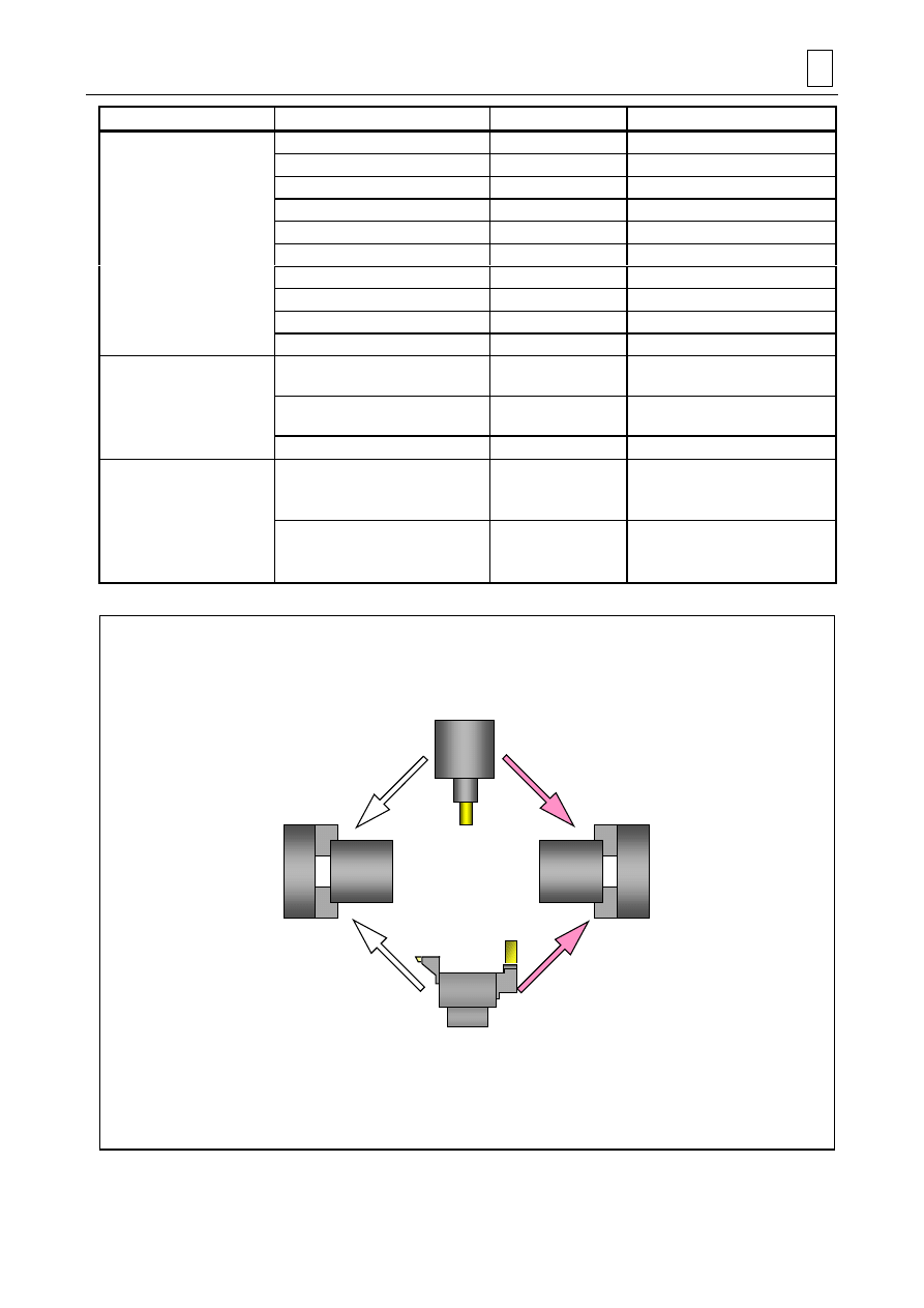
1.
Transfer to a USB memory
(1)
Copy the directory of the desired programs within the floppy disk into a USB memory by
using Explorer in an applicable, commercially available personal computer.
(2)
Use the DATA I/O display of the MAZATROL MATRIX to load the programs from the USB
memory.
D740PB0013
Floppy disk
(1)
(2)
USB memory
MAZATROL MATRIX
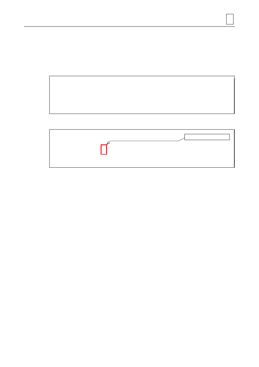
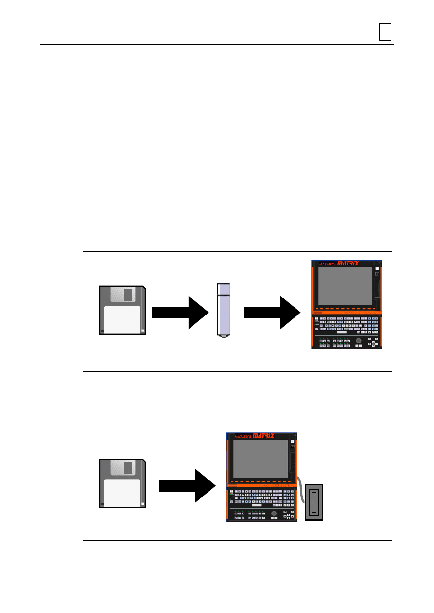
2.
Connection of a USB-use floppy-disk drive
(1)
Use the DATA I/O display to load the desired programs from the USB floppy-disk drive
connected to the MAZATROL MATRIX.
D740PB0014
Floppy disk
(1)
Floppy-disk drive
(USB-use)
MAZATROL MATRIX

5
INFORMATION FOR USERS WHO USE FLOPPY DISKS
5-2
- NOTE -
E
Document Outline
- SAFETY PRECAUTIONS
- BEFORE USING THE NC UNIT
- 1 OUTLINE
- 2 DIFFERENCES IN MAZATROL PROGRAMS
- 3 MAZATROL PROGRAM CONVERSION FUNCTION
- 4 DIFFERENCES IN EIA/ISO PROGRAMS
- 5 INFORMATION FOR USERS WHO USE FLOPPY DISKS
Wyszukiwarka
Podobne podstrony:
2006 mx pro tas
2006 mx pro sl
MX PRO Lo 80 100 120Service
2006 mx pro race
MAGIX Movie Edit Pro 18 MX Premium 11 0 2 2
Compare HUAWEI Nova 7 Pro 5G Vs Huawei P40 lite 5G GizBot
Mazatrol Fusion Conversational Programming Class for 640MT & MT Pro For Integrex Outline
2005 mx pro eta
2006 mx pro eta
2005 mx pro coil
2005 mx pro air
2006 mx pro
Mechanika Plynow Lab, Sitka Pro Nieznany
Corel Paint Shop Pro X Obrobka zdjec cyfrowych cwiczenia
competence vs performance
Dreamweaver MX Ćwiczenia
marcinstolp pro
więcej podobnych podstron