
BUSINESS MODELLING WITH UML:
DISTILLING DIRECTIONS FOR FUTURE RESEARCH
Sergio de Cesare, Mark Lycett
Department of Information Systems and Computing
Brunel University
Uxbridge, Middlesex, UB8 3PH
United Kingdom
{Sergio.deCesare, Mark.Lycett}@brunel.ac.uk
Dilip Patel
School of Computing, Information Systems and Mathematics
South Bank University
103 Borough Road
London SE1 0AA
United Kingdom
dilip@sbu.ac.uk
Keywords:
Business modelling, UML diagrams, Extensibility
Abstract:
The Unified Modelling Language (UML) was originally conceived as a general-purpose language capable of
modelling any type of system and has been used in a wide range of domains. However, when modelling
systems, the adoption of domain-specific languages can enable and enhance the clarity, readability and
communicability amongst modellers of the same domain. The UML provides support for extending the
language for defining domain-specific meta-elements. This paper approaches the UML from a business
perspective and analyses its potential as a business modelling language. The analysis proceeds along two
complementary paths: a critical study of UML diagrams and a description of UML extensibility mechanisms
for the definition of a business profile.
1. INTRODUCTION
The Unified Modelling Language (UML) has
emerged as a dominant software modelling language
within the object-oriented development community
(Kobryn 2000). Conceived as a general-purpose
language for the modelling of software systems, the
UML is defined as “a language for specifying,
visualising, constructing, and documenting the
artefacts of software systems, as well as for business
modelling and other non software systems” (OMG,
2000). This definition is based on the assumption
that the same underlying concepts and principles
characterise all systems (software and non-
software), regardless of the domain of applicability.
Consequently, the UML has been applied to a wide
range of domains from aerospace to e-commerce
underlining its potential for modelling systems that
are complex yet very different in nature. The
generality of the language is strengthened by a drive
for its standardisation. It is at present a de facto
standard of the Object Management Group (OMG)
who is currently proposing the UML specification
for international standardisation by the International
Organisation of Standardisation (ISO) (Kobryn
1999).
The assumption of general applicability
undoubtedly holds true when having to describe
systems whose behavioural patterns remain stable
over a long period of time. It may be argued,
however, that a standard modelling language alone
is not sufficient as the nature and characteristics of
the domains of applicability can be intensely
different. Business domains, in particular, have a set
of specific concepts and semantics, commonly

applied by people operating within that domain.
These concepts and the relationship amongst them
form the basis of a common understanding people
have of and within a domain. This shared
understanding can aid in the identification of
specialised metaconcepts, which UML recognises
via the dual concepts of extensibility mechanisms
and ‘profiles’. Extensibility mechanisms are
included in the language to allow modellers to
specialise detail (i.e., adapt it to context) without
having to modify the underlying modelling
language. Profiles represent tailored sets of
extensibility mechanisms that are applicable to
particular application domains.
With the above in mind, this paper explores the
following. Firstly, the extent to which the semantics
and the notation of the UML adhere to the
representation of the ‘fundamental’ generalised
concepts of the business domain. Secondly, the
extent to which extensibility mechanisms and
profiles are sufficient, as stand, to specialise
standard UML modelling elements to the needs of
the business domain. To enable this exploration, the
paper is structured as follows. Section 2 describes
the complex adaptive nature of business
organisations and the differences with other complex
systems. Since business complexity mainly derives
from an organisation’s complex behaviour, section 3
presents an overview of business process modelling
techniques, attempting to identify the basic concepts
underpinning any business model. On the basis of
these basic business concepts, Section 4 attempts to
assess the suitability of UML diagrams for business
modelling alongside their major limitations. Section
5 describes UML extensibility mechanisms and their
application to the definition of business specific
modelling concepts. The broad conclusion of the
work is that the UML, as stands, is not ideally suited
for business modelling and an agenda for further
research is presented in Section 6.
2. BUSINESS
COMPLEXITY
It is argued here that a case exists for
investigating whether special modelling techniques
and formalisations should be derived for business
organisations. This is based on the observation that
business organisations are complex systems that
constantly need to adapt and change to internal and
external factors in order to be competitive
(Johansson, McHugh et al. 1993). Business
organisations do not evolve in a stepwise fashion but
are best thought of as ‘emergent’ entities whose
features are products of continuous social
negotiation and consensus building (Truex,
Baskerville et al. 1999). Consequently, the
specification, visualisation, construction, and
documentation of business requirements is, at best,
only going to produce a static picture of a dynamic
situation (Lycett and Paul 1999). This is a unique
feature of social systems as, in natural systems, the
relationship between analyst and object is that of
‘concept to thing’, where only the analyst’s
knowledge may be subject to scrutiny (changing
knowledge of unchanging thing). This situation is
complicated in the social world where the object of
investigation exists within a pre-interpreted reality.
The relationship is that of ‘concept to concept’,
where both the observer’s knowledge and
knowledge of the observed may be placed under
scrutiny (changing knowledge of changing
knowledge).
Other factors contribute to aggravate this
modelling problem and help explain the internal
factors that generate change in the organisation.
Firstly, unacknowledged or unconscious motivation
and tacit skills may limit stakeholders’
understanding of themselves. Secondly, unintended
consequences and unacknowledged conditions (or
political factors) may limit the stakeholders and/or
analysts understanding of the social world. These
account for views expressed in the literature that
‘users cannot know what they want’ and ‘cannot
explain what they know’ (see Ackoff 1967; Parnas
and Clements 1986; Baskerville, Travis et al. 1992;
Jones and Walsham 1992; Paul 1994). Thirdly, in a
business, knowledge of problems is not/could not be
concentrated in one sole person. Business processes
are carried out within different organisational units
and by different people. As a consequence some
processes may become so complex as to not be
describable appropriately by anyone in the
organisation. In part, this relates to the extent that an
organisational problem exists as an independent
reality that can be modelled (Boland 1979;
Checkland 1981). Lastly, some knowledge relevant
to the problem situation may be difficult or
impossible to express within the descriptive
techniques available (Stage 1991); part reflecting a
view that descriptions of systems that abstract away
their complexity often abstract away their essence
(Brooks 1987).
3. BUSINESS
MODELLING
Business modelling can be defined as the
abstraction of the elements of a business

organisation and the relationships between them. In
modelling terms, the UML makes a claim as an
appropriate language and there is a nominal
applicability of UML elements (likely specialised)
and relationships. Most of the literature on business
modelling is focussed on business process
modelling, on the basis that the major complexities
of organisations derive from behaviour. A business
process can be defined as “a lateral or horizontal
organisational form that encapsulates the
interdependence of tasks, roles, people, departments
and functions required to provide a customer with a
product or a service” (Earl 1994, p.13). Business
processes define the dynamics of business
behaviour, act on entities or resources and are
carried out by parties. A party can be a person or an
organisational unit as defined by Fowler (1997).
Business process models can represent the
organisation as it currently behaves (descriptive ‘as-
is’) or as it could behave if changes in the business
processes are required (prescriptive ‘to-be’). Whilst
the forms of model are complimentary, the
prescriptive view is instrumental to strategies such
as business process reengineering (BPR) and
improvement (BPI). BPR is more radical in nature
and tends to revolutionise present business processes
(Hammer and Champy 1993), whereas the latter is
more gradual in nature looking at improving the
efficiency of business processes in an evolutionary
fashion (Davenport 1993).
A plethora of techniques exists that have been
applied to business process modelling, each
technique focusing on a specific aspect or set of
aspects of the business to model. Kettlinger et al.
(1997), in a study on methodologies, techniques and
tools for BPR, identify several techniques, most of
which (e.g. flowcharting and data flow
diagramming) derive from the software modelling
domain. It should be noted that a few of the
techniques listed are in reality methods, e.g. Socio-
Tech System Design and Soft Systems Method,
nonetheless these methods provide techniques for
the representation of different views of the business.
In order to understand whether the UML can add
positively to the above mix, an understanding of the
essential elements needed for business modelling is
required. Given that business organisations are
social systems, the characteristics of a business
therefore derive from those of a society. Homans
(1950) identifies the elements related to the
behaviour of social groups and then applies them
within a business context. These elements are:
concepts, activities, interactions and sentiments. The
latter can definitely be related to the informal side of
a business and its subsystems (e.g. information
system) and Homans defines a mutual dependency
between interaction and sentiment. Whilst it is
beyond the scope of this paper to look into the
informal aspects of an organisation and its influence
on the formal system, it is useful to underline that
only a few methods such as ETHICS (Mumford
1994) take ‘sentiments’ into account to a certain
extent. In a broad sense, however, the mapping of
the informal aspects to the formal aspects of an
organisation still remains an open research issue.
The elements identified by Homans (concepts,
activities and interactions) are implicitly also
defined by the techniques considered by Kettlinger
et al. (1997). Other elements also emerge. Ould
(1995) identifies the following basic concepts in
business process modelling: roles, actors, activities,
interactions, process goals and entities. These
concepts derive from STRIM, a modelling technique
based on Role Activity Diagramming. The reason
for considering these elements is directly connected
to the definition of business process given earlier in
this section. Actors interact through an
interdependency of tasks and business processes
achieve the goal of providing a customer with a
product or service. These elements or concepts
described by Ould (1995) will be taken into account
to assess the suitability of UML diagrams to
business modelling.
4. UML
DIAGRAMS
The UML has a rich set of diagrams for the
representation of both structural and behavioural
aspects of a system. These diagrams are to various
extents applicable during all phases of the system’s
lifecycle, from requirements specification to
implementation. A total of nine diagrams are defined
in the UML. This assortment of diagrams allows for
the representation of multiple perspectives,
especially for the representation of behaviour. Some
diagrams, namely statechart and activity diagrams,
are not derived from the object-oriented paradigm,
thus giving rise to potential problems in mapping
them to other diagrams of the system model
(Berkem 1998).
Although business modelling and business
process modelling are mentioned in different parts of
the UML specification, the documentation (OMG
2000) lacks a valid argumentation as to how the
individual diagrams can be applied in the context of
business modelling. The UML diagrams are
summarised for reference in Table 1. For each

diagram its potential to model each of the basic
business concepts is indicated. The business
concepts considered in this section are those
identified by Ould (1995).
The following subsections describe the potential
of the UML diagrams for business modelling and
present their main limitations in terms of their role in
business modelling and problems related to the
mapping between models and diagrams. Since
implementation diagrams model software
components and run-time processing they will not be
discussed in this section.
Table 1: UML diagrams and business modelling concepts.
4.1 Use
Case
Diagrams
Description
Use case diagrams model the functionality of a
system, as it is visible to external actors that
stimulate this functionality. Use cases have been
introduced by Jacobson et al. (1992) and have
proven to be an excellent tool for capturing high-
level system requirements. Use cases capture the
system as it is viewed from the outside and depict
the interaction between the system and external
actors. Actors lie outside of the system boundary.
Shifting the boundary of the system can provide a
useful mechanism for understanding how business
functionality (behaviour) maps to the high-level
functionality of the computer-based information
system. Fig. 1 illustrates such an example.
Fig. 1 illustrates two use case diagrams. Fig. 1a
represents functionality at a business level in which
the boundary is placed around the entire business
organisation. All functionality represented at this
level is seen by actors standing outside the business
and interacting with it, e.g. customers, suppliers,
revenue service, etc. Two use cases are depicted in
fig. 1a (order products and deferred payments). In
fig. 1b the system boundary is taken to a lower level,
Business Modelling Potential
Section Diagram
Description
R
O
L
E
S
A
C
T
O
R
S
A
C
T
I
V
I
T
I
E
S
I
N
T
E
R
A
C
T
I
O
N
S
P
R
O
C
E
S
S
G
O
A
L
S
E
N
T
I
T
I
E
S
4.1
Use case
Models the functionality of the system as it is visible to external actors
that stimulate this functionality.
•
•
•
Class
Models the static part of a system in terms of classes, relationships
amongst classes and their packaging.
•
•
4.3
Object
Models the representation of instances of class models.
•
•
Collaboration
Models object interaction via message passing placing emphasis on the
roles in the interaction and their links to each other.
•
•
•
•
4.2
Sequence
Models object interaction via message passing placing emphasis on the
sequence of interactions.
•
•
•
•
Statechart
Models the states and state transitions of an object of a given class.
•
•
4.4
Activity
Models the flow of activities defined for any given procedure.
•
•
Component
Models the dependencies amongst software components.
Not considered
Deployment
Models the configuration of run-time processing elements and the
software components, processes, and objects that live in them.
Not considered
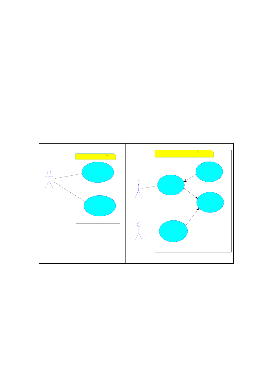
that of the computer-based information system. In
this specific instance, the actors lying beyond the
system boundary and interacting with the system are
workers of the organisation (sales clerk and finance
clerk). The two use case diagrams can be mapped to
one another to form an initial mapping between
business and computer-based information system
models. In this very simplified example:
Order products maps onto process order, process
high value order and browse profile;
Deferred payment maps onto arrange deferred
payment and browse profile.
The business metaconcepts that use cases are
capable of modelling are actors and process goals.
Actors are explicitly represented; process goals are
represented by one or more use cases. A use case
does not necessarily coincide with an entire business
process; however, groups of use cases can map into
one process to achieve a goal. In Fig. 1a the use
cases order products and deferred payment may be
mapped each to a corresponding business process,
whereas in Fig. 1b one process can be mapped to the
use cases process order, process high value order
and browse customer profile. The other business
process can be mapped to the use cases arrange
deferred payment and browse customer profile.
A role provides another business metconcept that
can be represented in use case diagrams. Modellers
often incur into some ambiguity between the
concepts of actor and role. An actor plays a role
when interacting with the system. For example, a
company can play the role of a customer or a
supplier whether it is buying or selling goods or
services. Hence the representation of an actor
implicitly states a role. Roles can also be modelled
explicitly by generalising/specialising an actor. In
Fig. 1b sales clerk and finance clerk can be modelled
as specialisations of clerk.
Figure 1: Different levels of representation with use case diagrams.
Limitations
In the modelling of actors, process goals and
roles, use cases per se do not present major
limitations. Problems can however arise when
mapping use case diagrams to other diagrams. Since
a use case merely models high-level functionality as
one or more actors perceive it, the internal activities
performed within the organisation to achieve such
functionality needs to be represented elsewhere,
such as an activity diagram. As a consequence,
integration and traceability amongst use case
diagrams and other UML diagrams becomes an
important issue (Berkem 1998). This matter will be
discussed further in sections 4.2 and 4.4.
4.2 Interaction
Diagrams
Description
Fig. 1b
Fig. 1a
Sales Clerk
Finance
Clerk
Process
order
Browse
Customer
Profile
Process
high value
customer
Arrange
deferred
payment
<<include>>
<<include>>
<<extend>>
Computer-Based
Customer
Order
product
Deferred
payment
Business Organisation

Interaction diagrams can assume two forms:
collaboration and sequence diagrams. In object-
oriented modelling an interaction occurs between
two objects when one object sends a message to
another object. The sending object requests an
operation and the receiving object is responsible for
knowing how to carry out that operation and its
execution. A set of interactions or collaboration is
defined within an interaction diagram in order to
‘realise’ a use case. A collaboration diagram
represents an interaction organised around the roles
in the interaction and their links to each other. A
sequence diagram represents the collaboration
differently highlighting the temporal sequence of the
interactions. Although collaboration and sequence
diagrams are considered semantically equivalent, a
sequence diagram provides better visual support for
branching. This allows for a clearer representation of
multiple scenarios of a use case on the same
diagram, whereas the representation of branching in
a collaboration diagram becomes less readable as the
number of collaborating objects and scenarios grow.
In business process modelling with RAD
techniques, interactions are normally defined
between roles and not between objects. The meaning
of interaction is slightly different than that assigned
to the term in the UML and object-orientation in
general. For instance, Ould (1995) explains business
interactions through the following examples: a
manager delegating a task to a subordinate, or the
handing over of a report. In both examples
interaction occurs between roles played by humans.
In collaboration and sequence diagrams interactions
can occur between objects or between actors and
objects.
For example, a business process aimed at
carrying out a design project can be defined by the
following activities: a designer prepares an estimate,
which is then sent to the project manger (Ould
1995). In a RAD the designer (role) prepares an
estimate (activity) and the project manager (role)
obtains the estimate from the designer (interaction),
hence interaction between roles. In an interaction
diagram the same example could be modelled as
follows:
The designer (actor) sends a message to the
‘estimate’ object invoking the ‘prepare estimate’
operation (interaction between actor and object);
The ‘estimate’ object then sends the prepared
estimate as a result back to the designer;
The ‘estimate’ object then sends a message to
itself invoking the ‘send to project manager’
operation;
The ‘estimate object’ sends the estimate to the
project manager (actor);
As a point of note, it is beyond the scope of this
paper to delve into architectural issues related to the
distinction between boundary, control and interface
objects as described by Jacobson et al (1992). For
this reason the estimate object described in the
example is a hybrid of the above-mentioned types.
Although interactions are defined and modelled
differently in RAD and UML, the end result is
equivalent. In the previous example both in the
RAD-based and UML-based textual descriptions,
the overall result has been an interaction between the
designer and the project manager. This is important
at a business level because it emphasises the
complementary roles of two different types of
diagrams, in which the former is aimed at
representing flow of activities, whereas the latter
models flow of messages amongst objects.
Limitations
Besides interactions, collaboration and sequence
diagrams have the potential of representing actors,
process goals and entities. Since interaction
diagrams generally map to realisations of use cases,
the actors and process goals are the same as those
defined in use case diagrams. Entities are defined as
objects whose structural and behavioural properties
are defined in class diagrams. A major limitation of
interaction diagrams is their inability to link to other
collaborations. This is fundamental when modelling
complex business processes in which various levels
of refinement may be necessary in order to manage
the underlying complexity. For this purpose, the
Objectory method (Jacobson, Christerson et al.
1992) defines the concept of probe, which can be
used within a sequence diagram to insert additional
behaviour defined in a use case.
4.3 Class and Object Diagrams
Description
Class and object diagrams are directly capable of
representing business entities as objects. Objects are
logically manipulated during business processes.
The shared attributes and operations of objects are
defined in classes. A class is a description of a set of
objects sharing the same attributes, operations,
relationships and semantics. Class diagrams also
represent different types of relationships amongst
classes. When two classes are associated to one
another, the association can carry on both ends the
name of roles played by the objects in the
relationship. For example, in the case of a payment
there is a relationship between a ‘person’ object and
a ‘payment’ object. In this association the person
making the payment plays the role of the payee.

Limitations
Given the static nature of classes/objects, these
diagrams seem to be adequate for defining business
entities; however, as section 5 will discuss, classes
can be stereotyped (i.e. specialised at a
metamodelling level) in order to enhance class
modelling for business organisations.
4.4 State and Activity Diagrams
Description
Statechart diagrams, also known as state
diagrams or state machines, model the sequence of
states and state transitions that an object traverses
during its lifetime. Although state diagrams have
originally been defined for modelling real time
systems (Harel 1987), they can be used to model
workflows manipulating and/or transforming one
object. State diagrams do not explicitly model any of
the business metaconcepts defined in section 3,
however when an object is in a given state, different
types of activities can be performed. Whether a state
diagram can represent a whole business process is
debatable, since the complexity of business
processes usually encompasses several objects.
More appropriate for this type of modelling are
activity diagrams.
The contribution of activity diagrams to business
process modelling seems to be promising, but as yet
the potential of activity diagrams has not been fully
exploited in this area. Activity diagrams have been
originally defined with the purpose of modelling the
computation and flow of control of the algorithm of
an operation. The UML specification defines an
activity diagram in terms of state machines. An
activity diagram is a variation of a state machine in
which the states represent the performance of actions
or subactivities (OMG 2000). Although correct, this
definition may generate some confusion when trying
to conceptually associate states/activities with
objects. In a state diagram all the states are defined
for objects of a specific class, in an activity diagram
the action states do not necessarily (and generally do
not) refer to actions performed by the same object.
Activity diagrams presently lie outside of the
object-oriented philosophy. They are not
semantically integrated with other diagrams, as are
use case, interaction and class diagrams. The UML
specification does not adequately define the
relationship between the elements of activity/state
diagrams and elements of other diagrams. This
represents a general problem/pitfall of the current
version of the UML, with implications of a more
specialised nature when taking into account the
business domain.
The main elements of an activity diagram are
action states. UML 1.3 introduces subactivity states,
which are basically invocations to other activity
diagrams. A transition from one state to another is
triggered by the termination of the action or
subactivity. With the term activity the UML refers to
the set of actions and transitions forming the entire
activity diagram. An action state represents the
execution of an atomic action, typically the
invocation of an operation. An activity diagram,
therefore, in a way reflects the contents of
interaction diagrams. Whilst interaction diagrams
represent objects passing messages, activity
diagrams represent the operations of the messages
being passed. In other words, in an activity diagram
the emphasis is placed on the operations rather than
the objects they belong to. Within the context of
object-oriented business modelling, an action
therefore generally maps onto an operation and a
subactivity to a collaboration. In the light of this the
link between activity and interaction diagrams
becomes more apparent.
Limitations
Activity diagrams are therefore capable of
representing business activities. The representation
of business processes is also possible, however, as
Berkem (1998) points out, business process
modelling requires, amongst other things, the
representation of past states of objects to allow for
better decisions and design with an evolutionary
pattern. Although referred specifically to activity
diagrams, these comments could also be applied to
use case and interaction diagrams. None of these
diagrams are, as they stand, able to model past states
of objects and evolutionary patterns. Such
requirements can be modelled ad hoc within the
system model (e.g. by defining a composite class
modelling its present and past states), nonetheless
the issue remains at a metamodelling level.
Roles can also be modelled in activity diagrams
by partitioning the diagram in so-called swimlanes.
The UML does not assign the term role to
swimlanes. In the UML swimlanes are merely an
arbitrary partitioning of elements with no semantics
(Kleppe and Warmer 2000); hence the underlying
roles can represent anything from an object to an
organisational unit or functional area. There is no
constraint imposing the nature of the role nor the
consistency amongst the roles defined (e.g. all
objects, all organisational units, etc.) This deficiency
also restricts the application of the concept of
responsibility to activity diagrams.

5. UML
EXTENSIBILITY
Business systems form a proper domain, in
which individuals communicate and interact by
using a set of specialised concepts. The semantics of
these concepts and the relationships amongst them
are defined by the context of the business domain.
Common concepts allow individuals to have a
common understanding of the domain they operate
in. This common understanding is generally referred
to as ‘ontology’ and definition of ontological
specialisations or domain specific semantics of a
modelling language is an emerging issue amongst
the UML community. UML 1.3 introduces profiles,
which serve the purpose of defining extensions to
the language. Profiles are containers for the three
extension mechanisms that are currently legal within
the UML: stereotypes, tagged values and constraints.
These extensions are not mutually exclusive.
A stereotype is defined by specialising a pre-
existing modelling element. For example, subsystem
is an example of a stereotyped package. A
subsystem, just like a package, groups logically
related concepts. Modelling elements are the basic
building blocks of a language, e.g. class, association,
operation, attribute, etc. A stereotype is defined by a
name and its semantics. The new semantics add to
those of the specialised modelling element. Since
stereotypes are specialisations of pre-existing
modelling elements, the stereotyped element
behaves like the element it derives from plus some
additional behaviour defined by the new semantics.
Stereotypes prevent a modelling language from
becoming overly complex and represent the most
sophisticated extension mechanism (Eriksson and
Penker 1998). Expanding the above example a
subsystem could represent an organisational unit of
an enterprise or the monitoring subsystem of an
environmental control system. The new semantics of
the subsystem stereotype consists of representing
elements, which together constitute a system part of
a greater system being modelled.
Constraints restrict the semantics or usage of
modelling elements and represent rules that restrict
the semantics of one or more modelling elements.
The new semantics is represented in the model
simply by specifying conditions that must be held
true. For example, in a university only final year
students have a supervisor for their project. Hence
the association between student and academic staff
representing this association can be restricted to final
year students {year = final year}. Tagged values
qualify a modelling element with pairs of name-
value information. For example, software
components can be labeled with tagged values
representing the author and the version: {Author =
John Smith}, {Version = 1.3}.
An initial attempt in extending the UML has
been made in version 1.1. UML 1.1 integrates within
its complete documentation the UML Extension for
Business Modelling document. However, as the
document emphasises, the extension merely serves
the purpose of registering the document. The current
version of the UML has not completed these
extensions either. The documentation only provides
a list of thirteen stereotypes; neither tagged values
nor constraints are defined. Table 2 lists the thirteen
business stereotypes.
Apart from a few of the stereotypes in Table 2
(e.g. work unit and worker), most of them only
vaguely resemble business-oriented concepts. They
are instead more oriented toward UML itself, i.e.
based on UML modelling elements such as use
cases. In fact use case models, systems and packages
are quite general and applicable throughout all types
of systems. The same can be said of object models
and systems.
Metamodel Class
Stereotype Name
Model
Use case model
Package
Use case system
Package
Use case package
Model Object
model
Subsystem Object
system
Subsystem Organisation
unit
Subsystem Work
unit
Class Worker
Class Case
worker
Class Internal
worker
Class Entity
Collaboration
Use case realisation
Association Subscribes
Table 2: UML defined business stereotypes.
Whilst extension mechanisms themselves work
quite well, the UML extension does not specify how
the business stereotypes have been derived, nor does
it seem complete. The UML business profile cannot
be considered a formal attempt to define ‘the set’ of
business concepts; however although the UML
Extension for Business Modelling lacks in the
definition of a set of recurrent business modelling
elements, this documentation can be used as a
starting point. In this direction Capozza et al. (1999)
propose various business stereotypes categorised
into seven groups (business i/o, persons, space-
related concepts, time-related concepts, logical
aggregates, functional concepts and other general
concepts). Eriksson and Penker (2000) propose

another set of business extensions to the UML. The
future work of the OMG will most likely also be
orientated toward the expansion of the extension for
business modelling and this provides a major
direction for future research.
6. CONCLUSION
The UML is a general-purpose modelling
language potentially capable of modelling any type
of system. For specific domains, however, it may be
useful to work with specialised modelling concepts
reflecting recurrent semantics of the domain. The
business domain is one such example. Business
complexity is augmented due especially to the
uncontrollable and unpredictable nature of change
and evolution of business requirements. This paper
has presented a critical analysis of the UML in the
context of business modelling. The analysis has
focussed on two main problem areas: suitability of
UML diagrams to model business organisations and
the use of the UML for abstracting high-level
business-specific concepts. In both areas the UML
currently presents deficiencies and research is not
fully developed.
The main limitations of UML diagrams to
business modelling can be directly or indirectly
related to the use and/or semantics of activity
diagrams and can be summarised in the following
points:
Business process modelling with the UML has
not been adequately achieved. Although activity
diagrams provide potential support for this purpose,
they are not semantically integrated with other
dynamic modelling diagrams (use case and
interaction diagrams).
The representation of roles is an important part
of an activity-based representation of a business
process. Roles can be represented in activity
diagrams by partitions or swimlanes, however the
semantics of partitions are not defined in the UML.
UML diagrams provide no mechanism for the
representation of past states of objects or for that of
evolutionary patterns.
Inability of sequence diagrams to refer to or
invoke other collaborations via mechanisms such as
probes.
Business organisations continually change and
adapt with inevitable consequences on business
requirements and models. These continuous
modifications produce ripple effects throughout the
business model(s) and model diagrams. A change in
one diagram conceptually relates to one or more
elements of other diagrams. Hence a change in one
part of the model maps semantically to other parts
and such semantic relationships need to be formally
defined within the specification of the modelling
language in order to map the effects of a change
throughout the model. For this reason, semantic
consistency throughout UML diagrams and
modelling elements is vital to business modelling.
Further research is necessary in order to
understand what elements of the business need to be
modelled. Significant effort should be focussed on
identifying other business concepts besides those
considered in this paper (roles, actors, activities,
interactions, process goals and entities). Examples of
such concepts are business services, rules
(Rouvellou, Degenaro et al. 2000) and events
(Snoeck, Poelmans et al. 2000). Future research
should also be directed toward the definition of a
UML profile for the business domain. Besides
providing a set of business-specific metaconcepts, a
specialised profile could enhance the semantics of
those UML modelling elements that are limited in
the way they currently represent business concepts.
This could also lead to a better integration of UML
diagrams within a business model. A further step in
the evolution of the UML is its use as an ontology
language (Cranefield and Purvis 1999). Research in
the area of UML profiling could provide a better
understanding of how and to what extent UML
extension mechanisms and elements can be applied
to defining ontologies.
REFERENCES
Ackoff, R. (1967). “Management
Misinformation Systems.” Management Science
14(4): 147-156.
Baskerville, R., J. Travis, et al. (1992). Systems
without Method: The Impact of New Technologies
on Information Systems Development Projects. The
Impact of Computer Supported Technologies on
Information Systems Development. K. Kendall, J.
DeGross and K. Lyytinen. Amsterdam, Elsevier
Science Publishers, B.V., North Holland Press: 195-
213.
Berkem, B. (1998). Formalizing a bridge from
the UML's Activity Diagram to Use Cases.
Workshop On the Usage of the UML - OOPSLA
'98, Vancouver.
Boland, R. J. (1979). “Control, Causality and
Information System Requirements.” Accounting,
Organisations and Society 4: 239-275.

Brooks, F. P. (1987). “No Silver Bullet: Essence
and Accidents of Software Engineering.” IEEE
Computer 20(4): 10-19.
Capozza, F., S. deCesare, et al. (1999).
Modelling Extensions for the Business Domain. 12th
International Conference on Software and Systems
Engineering and their Applications, Paris, France.
Checkland, P. (1981). Systems Thinking,
Systems Practice. Chichester, John Wiley and Sons.
Cranefield, S. and M. Purvis (1999). UML as an
Ontology Modelling Language. IJCAI-99 Workshop
on Intelligent Information Integration.
Davenport, T. H. (1993). Process Innovation.
Reengineering Work through Information
Technology, Harvard Business School Press.
Earl, M. J. (1994). “The New and Old of
Business Process Redesign.” Journal of Strategic
Information Systems 3(1): 5-22.
Eriksson, H. E. and M. Penker (1998). UML
Toolkit, John Wiley & Sons.
Fowler, M. (1997). Analysis Patterns, Addison-
Wesley.
Hammer, M. and C. Champy (1993).
Reengineering the Corporation: A Manifesto for
Business Revolution. New York, Harper Business.
Harel, D. (1987). “State charts: A Visual
Formalism for Complex Systems.” Science of
Computer Programming 8: 231 - 274.
Homans, G. C. (1950). The Human Group. New
York, Harcourt, Brace.
Jacobson, I., M. Christerson, et al. (1992).
Object-Oriented Software Engineering: A Use Case
Driven Approach, Addison-Wesley. ACM Press.
Johansson, H. J., P. McHugh, et al. (1993).
Business Process Reengineering, BreakPoint
Strategies for Market Dominance, John Wiley&
Sons.
Jones, M. and G. Walsham (1992). The Limits of
the Knowable: Organisational and Design
Knowledge in Systems Development. The Impact of
Computer Supported Technologies on Information
Systems Development. K. Kendall, J. DeGross and
K. Lyytinen. Amsterdam, Elsevier Science
Publishers: 195-213.
Kettlinger, W. J., J. T. C. Teng, et al. (1997).
“Business Process Change: A Study of
Methodologies, Techniques, abd Tools.” MIS
Quarterly 21(1): 55-80.
Kleppe, A. and J. Warmer (2000). Making UML
Activity Diagrams Object-Oriented. Technology of
Object-Oriented Languages and Systems (TOOLS
33), St. Malo, France, IEEE Conference
Proceedings.
Kobryn, C. (1999). "UML 2001: A
Standardization Odyssey." ACM Communications
42(10).
Kobryn, C. and T. Weigert (2000). "OMG UML
2.0 RFPs." ftp://ftp.omg.org/pub/docs/ad/00-09-
05.pdf.
Lycett, M. and R. J. Paul (1999). “Information
Systems Development: A Perspective on the
Challenge of Evolutionary Complexity.” European
Journal of Information Systems 8(2): 127-135.
Mumford, E. (1994). “New Treatment or Old
Remedies: Is Business Process Reengineering Really
Socio-Technical Design?” Journal of Strategic
Information Systems 3(4): 313-326.
OMG (2000). OMG Unified Modeling Language
Specification:
http://www.rational.com/media/uml/post.pdf.
Ould, M. (1995). Business Process: Modelling
and Analysis for Re-engineering and Improving,
Wiley.
Parnas, D. L. and P. Clements (1986). “A
Rational Design Process: How and Why to Fake It.”
IEEE Transactions on Software Engineering 12(2):
251-257.
Paul, R. J. (1994). “Why Users Cannot 'Get
What They Want'.” International Journal of
Manufacturing Systems Design 1(4): 389-394.
Eriksson, H. E. and M. Penker (2000). Business
Modeling With UML: Business Patterns at Work,
John Wiley & Sons.
Rouvellou, I., L. Degenaro, et al. (2000).
Extending Business Objects with Business Rules.
Technology of Object-Oriented Languages and
Systems (TOOLS 33), St. Malo, France, IEEE
Conference Proceedings.
Snoeck, M., S. Poelmans, et al. (2000). An
Architecture for Bridging OO and Business Process
Modelling. Technology of Object-Oriented
Languages and Systems (TOOLS 33), St. Malo,
France, IEEE Conference Proceedings.
Stage, J. (1991). The Use of Descriptions in the
Analysis and Design of Information Systems.
Collaborative Work, Social Communications and
Information Systems. P. Kerola, R. Lee, K. Lyytinen
and R. Stamper. Amsterdam, Elsevier Science
Publications: 237-260.
Truex, D. P., R. Baskerville, et al. (1999).
“Growing Systems in Emergent Organisations.”
Communications of the ACM 42(8): 117-123.
Winograd, T. and F. Flores (1986).
Understanding Computers and Cognition. Norwood
NJ, Ablex.
Document Outline
- INTRODUCTION
- BUSINESS COMPLEXITY
- BUSINESS MODELLING
- UML DIAGRAMS
- UML EXTENSIBILITY
- CONCLUSION
- REFERENCES
Wyszukiwarka
Podobne podstrony:
Business modeling with UML id 9 Nieznany (2)
Wind Turbine and Grid Connection Modelling with PSCAD
Nlp Steve Andreas Modelling With Nlp
Advanced Modeling with UML (OMG)
Computer Modelling with CATT Acoustic Theory and Practice of Diffusion Reflection and Array Modelin
Design Java Apps with UML 600 dpi
Business Process Modeling with EPC and UML
Dance, Shield Modelling of sound ®elds in enclosed spaces with absorbent room surfaces
Gender Games Doing Business With The Opposite Sex
Getting Started with Data Warehouse and Business Intelligence
Introduction to business modeling using the UML
Rational UML Profile for business modeling IBM
Dance, Shield Modelling of sound ®elds in enclosed spaces with absorbent room surfaces
Getting the edge in business with NLP
Sitesell Make Great Money With This Free Affiliate Program From Home Business Ebook
więcej podobnych podstron