
Prepared for:
Advancing Colorado’s
Renewable Energy
Program
Colorado Department of Agriculture
700 Kipling St, Suite 4000
Lakewood, CO 80215-8000
Exploring the Viability of Low
Head Hydro in Colorado’s Existing
Irrigation Infrastructure
Interim Report
Summary of Available Low Head Turbine Technologies
Interim Report
- Low Head Turbines
Prepared by:
Water Resource Advisors for the West
1499 W. 120
th
Ave., Suite 200
Denver, CO 80234
Phone: 303-452-6611
Fax: 303-452-2759
www.applegategroup.com
September 2010
AG File No. 10-101
Engines and Energy Conversion Laboratory
Department of Mechanical Engineering
430 N. College Ave
Fort Collins, CO 80524

TABLE OF CONTENTS
Introduction ............................................................................................................................................................................... 1
General Turbine Technologies ........................................................................................................................................... 2
Low Head Turbines ............................................................................................................................................................ 2
Site Conditions ..................................................................................................................................................................... 2
Turbine Selection Charts ................................................................................................................................................. 3
Types and Sizes of Generators ...................................................................................................................................... 5
Interconnect Approval Process ..................................................................................................................................... 7
Interconnection Cost ......................................................................................................................................................... 8
Revenue .................................................................................................................................................................................. 8
Additional Comments ....................................................................................................................................................... 9
Energy Systems and Design – LH1000 .................................................................................................................... 11
Power Pal ............................................................................................................................................................................. 12
Canyon Hydro – KAPLAN Turbine ............................................................................................................................. 13
Toshiba International – Hydro-eKIDS ...................................................................................................................... 14
Very Low Head Turbine ................................................................................................................................................. 15
Gilkes – Kaplan Turbine ................................................................................................................................................. 16
Mavel ...................................................................................................................................................................................... 17
Voith Hydro ......................................................................................................................................................................... 18
Andritz Hydro..................................................................................................................................................................... 19
HydroCoil Power ............................................................................................................................................................... 21
Ritz-Atro – Hydrodynamic Screw Turbine ............................................................................................................. 22

Alternative Hydro Solutions – Darrieus Water Turbine ................................................................................... 24
Hydrovolts ........................................................................................................................................................................... 25
Elephant Butte Irrigation District .............................................................................................................................. 26
Water Vortex Power Plant ............................................................................................................................................ 27

Low Head Turbines | Introduction
1
INTRODUCTION
Applegate Group, Inc. was awarded a Colorado Department of Agriculture ACRE grant to perform a
research study entitled “Exploring the Viability of Low Head Hydro in Colorado’s Irrigation
Infrastructure”. The study will be performed by taking a state-wide look at existing infrastructure
and current technologies. This report summarizes the progress of this research study which is
approximately 50% complete with a final report anticipated in Spring 2011. The main goals of this
study are to research low head hydro turbine technologies, explore interconnection issues, and to
quantify the potential of Colorado’s irrigation infrastructure to produce low head hydroelectricity.
To complete these goals five tasks were identified;
Task 1: Research low head hydropower technologies
Task 2: Inventory the infrastructure available in Colorado for low head hydropower generation
Task 3: Investigate interconnection issues
Task 4: Compare the technologies to the hydraulic structures
Task 5: Estimate a statewide potential
Task 1 has been completed and the result of this research is included in this report. A preliminary
overview of interconnection issues is also included. Task 2 is currently in progress; surveys are in
the process of being distributed to irrigation providers, and results are being collected. Once the
results of Task 2 are compiled, the technologies in this report will be compared with the hydraulic
structures described in the surveys. Two “project location” sites will be chosen from the surveys
and investigated in more detail. The interconnection issues associated with those sites will be
explored, as well as specific turbines and power production estimates. More specifics regarding the
applicability of these turbines to site conditions will be included in the final report.
A total of sixteen turbine manufacturers have been identified and are listed in this report. These
turbines are either impulse or reaction turbines, including propeller type, a hydroengine, screw
type turbines, hydrokinetic turbines and waterwheels. The head and flow ranges of each turbine
are mentioned and visually displayed in the attached chart. Contact information including websites
and telephone numbers are included for each manufacturer. All of the manufacturers listed in this
report have either been responsive to inquiry or have information on their websites.
Low Head Turbines | General Turbine Technologies
2
GENERAL TURBINE TECHNOLOGIES
LOW HEAD TURBINES
Generally low head turbines are going to be of the reaction type. The water passing through a
reaction turbine loses its energy, or pressure, as it passes the turbine blades. The turbine must be
encased in a pressurized housing, and fully submerged in water. This is different from an impulse
turbine which changes the velocity of the water. Water is directed at the blades of an impulse
turbine with a high velocity nozzle, and the velocity of the water turns the blades. An impulse
turbine can be open to the air, and only needs a casing to control splash. All turbine types can be
classified into one of these two groups.
FIGURE 1: TYPES OF HYDROPOWER TURBINES
The turbines are listed from higher head to lower head. The turbines highlighted with red are
considered low head turbines, and examples of these turbines are discussed in this report.
SITE CONDITIONS
The two conditions that are used to choose the appropriate turbine for a site are head and flow rate.
The head is measured as the vertical distance between the highest and lowest water surface, minus
any losses that occur through that drop (such as pipe friction). The flow rate is a measure of all of
the water that will be passing through the turbine. Turbines can generally operate through a range
of flow rates, but the size of that range varies with turbine type. Also the efficiency of the turbine
lowers as the flow rate varies from the designed flow rate. This is something to consider when
choosing a turbine for a site. It is possible that the best turbine may not utilize all of the flow
available at high flow, so that the range can also cover the low flow periods. A detailed analysis of
the flow over time will need to be performed to choose a turbine that is best suited for a site. The
Hydropower
Turbines
Impulse
Pelton
Turgo
Francis
Cross Flow
Reaction
Propeller Type
(e.g. Kaplan)
Screw Type
Waterwheels
Hydrokinetic
High
Head
Low
Head
Low Head Turbines | General Turbine Technologies
3
power produced by a site can be estimated using the following equation, where head is in feet and
flow is in cubic feet per second.
efficiency
Flow
Head
Power
8
.
11
This equation can provide an estimate of the power available at a site, either high or low head, but
the turbine manufacturer should be contacted regarding the efficiency of a particular turbine, and
how that efficiency may vary with flow rate.
TURBINE SELECTION CHARTS
Turbine selection charts can be used as a starting point to determine which turbine may be
applicable to a particular site. The ranges shown are approximate, and the turbine manufacturer
should be contacted to verify that the turbine is appropriate for the site’s specific conditions. The
turbines may operate within the whole range shown, but the efficiency may decrease as you
approach the corners or edges of the range. Please use these charts as a starting point and a visual
approximatation of the range of turbine applicability. This is also not an exhaustive listing of all
turbines available. These are the turbines that we believe will be appropriate in Colorado’s
irrigation infrastructure for sites in the low head range, between 5 and 30 feet. For clarity the
charts have been divided into two subranges.
Details on each of the turbines displayed in the chart are listed in the following section. Also the
ranges for individual turbines are explained or displayed in the description.
FIGURE 2: VERY LOW HEAD RANGE TURBINE SELECTION CHART
1.0
10.0
1
10
100
1000
H
e
ad
(ft)
Discharge (cfs)
Turbines in the very low head range
VLH Turbine
LH1000
Power Pal
Mavel TM3
Mavel TM5
Mavel TM10
Natel Energy
Hydrowatt
Voith EcoFlow
Low Head Turbines | General Turbine Technologies
4
FIGURE 3: LOW HEAD RANGE TURBINE SELECTION CHART
5
50
1
10
100
1000
H
e
ad
(ft)
Discharge (cfs)
Turbines in the low head range
Toshiba S
Toshiba M
Toshiba L
Andritz
Ossberger
Canyon
Hydro Kaplan
Hydrocoil
Ritz-Atro
Voith Kaplan
Low Head Turbines | Interconnection Issues
5
INTERCONNECTION ISSUES
Pending completion of the project specific site surveys, the project team has not approached
Colorado utilities to inventory interconnect challenges for small hydroelectric plants. However, the
research on available turbines, coupled with existing knowledge of utility interconnect issues, can
highlight interconnect challenges. Interconnection of small generation stations is well understood;
there are few significant technical issues. Instead, issues are primarily economic, with technical
hurdles tending to increase implementation costs. The following techno-economic topics are
discussed in this section:
1) Impact of generator size and type on interconnect process and equipment.
2) Interconnecting to utility service
3) Electricity sales arrangements
TYPES AND SIZES OF GENERATORS
Figure 4 illustrates the range of possible power outputs for the turbines identified in this report.
Each red square represents the lowest quoted size for one turbine type. Each blue diamond
represents the largest quoted size. Sizes have been restricted to the size range of likely installations
– 5-30 ft of head and 100-1500 cfs of flow. Turbine types outside of this range are not plotted. Since
turbine efficiencies are not generally quoted in preliminary information, efficiencies of 70-75%
were assumed for all turbine types. Considering these factors, output power is expected to lie
between approximately 0.2 KW and 3000 KW in size.
FIGURE 4: ESTIMATED OUTPUT SIZE RESTRICTED TO LIKELY INSTALLATION LOCATIONS
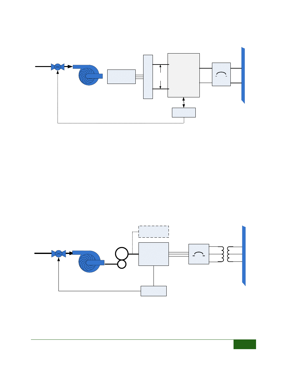
Similar to wind energy, smaller turbines tend to utilize power electronics – typically an inverter or
variable-frequency drive – to interconnect with the electrical power system as shown in Figure 5.
The inverter/drive provides synchronization with the utility and controls power production. The
system controller computes the correct loading on the turbine and generator to maximize power
0.1
1.0
10.0
100.0
1,000.0
10,000.0
1.0
10.0
100.0
Es
ti
m
at
e
d
T
u
rb
in
e
P
o
w
e
r
(K
W
)
Head (ft)
Range of Turbine Output Power
Max Power (KW)
Min Power (KW)
Low Head Turbines | Interconnection Issues
6
production. While shown as a single-phase connection, power electronics systems can connect to
three-phase circuits as well.
FIGURE 5: TYPICAL INTERCONNECT FOR SMALL TURBINES
Since turbine loading can be controlled electrically through the generator, water flow can, to some
extent, be controlled indirectly by adjusting turbine speed. As a result, some designs do not require
automatic control of the water flow rate (dotted line in figure), while other designs will require
traditional gate control. Most inverter-based systems can operate the turbine at variable speeds,
which can provide higher efficiencies at variable flow rates.
Larger turbines typically couple directly to three-phase electrical generators, most often through
fixed-ratio shaft couplings, belts or gears. The generators connect directly to the electrical grid, as
shown in Figure 6. Direct connection benefits from higher efficiency than the inverter system, but
suffers from fewer control options. Since the generator speed is effectively locked to the fixed
frequency of the grid, the turbine typically rotates at a constant speed, governed by the gears or
belts coupling the generator and turbine. Since speed is fixed, flow control must be provided
externally in most cases, either through automatic or manual adjustment of intake gates.
FIGURE 6: TYPICAL INTERCONNECT FOR LARGER TURBINES
Directly coupled systems must also be synchronized to the utility before closing the interconnect
breaker. In some cases, a “starting circuit” or starting motor is required. Other systems utilize flow
control to adjust the generator speed, bringing the system in synchronization with the utility.
Inverter or
Drive
System
3-Phase
Generator
R
e
c
ti
fi
e
r
2
4
0
-4
8
0
V
C
ir
c
u
it
Variable
DC
Controller
Breaker
U
ti
lit
y
Generator
Gears or
Belts
Transformer
(Optional)
Controller
Starting
Circuit
Breaker

Low Head Turbines | Interconnection Issues
7
INTERCONNECT APPROVAL PROCESS
Interconnection processes are governed by two primary factors – size and the type of generator.
From a regulatory standpoint, most generator sizes anticipated in this study slot most projects into
the “expedited approval” categories currently recognized by the Federal Energy Regulatory
Commission
1
(FERC) and the Colorado Public Utilities Commission
2
(C-PUC). This should reduce the
engineering costs and complexity of generation projects. Two key factors are considered to classify
a project for expedited approval – the size of the new project, and the total amount of generation
connected on a single feeder (i.e. distribution line from the nearest substation). Given the relatively
low penetration of distributed generation in Colorado, it is likely that the project size will be the
most important classification criteria. This topic will be further investigated in future stages of this
project.
Most distribution utilities (i.e. retail electric utilities) in Colorado have exclusive power purchase
agreements with a single generation or generation & transmission (G&T) operator. For example,
many rural cooperatives have exclusive provider agreements with Tri-State Transmission and
Generation. These agreements often limit the size of individual projects and total amount of power
the utilities can purchase from other sources, such as hydroelectric projects. Larger units, e.g. those
≥ 1000 KW, may require “power purchase agreements” directly with the G&T operator. The impact
of existing power purchase agreements on small hydroelectric projects will be assessed later in this
project, in general for the entire state, and in detail for specific study sites.
The type of generator also impacts certain technical interconnect requirements. The primary driver
behind this difference is the “fault current contribution” of the generation system. “Fault current”
can be casually described as how much instantaneous current a device produces if there is a fault
(e.g. a short circuit) between the device and another part of the grid. Power electronic systems, like
inverters, tend to have low fault current contributions. Rotating machines tend to have higher fault
current contributions. Therefore, inverter-based systems (Figure 5) typically require limited
engineering work prior to interconnect, while rotating machine systems (Figure 6) may require
more extensive and expensive simulation studies before the project will be approved. In addition,
many utilities now have extensive experience with photovoltaic inverters, leading to additional
comfort with inverter-based generation. Therefore, inverter-based systems may reduce
interconnection complexity.
Generation equipment must meet applicable standards before utilities will allow interconnection.
UL approval is typically required for most systems, although larger, engineered systems may only
require UL approval for components, and not on the entire installation. In addition, generation
equipment must typically meet additional standards, including:
IEEE 1547 – governs how generators synchronize with the grid and how they respond if
electrical service is lost.
1
FERC Order No. 2006, Standardization of Small Generator Interconnection Agreements and Procedures, USA
Federal Energy Regulatory Commission, May 12, 2005.
2
Colorado Public Utilities Commission, Code of Colorado Regulations (CCR) 723-3, Part 3, Rules Regulating Electric
Utilities, March 30, 2010.

Low Head Turbines | Interconnection Issues
8
IEEE 519 – specifies how “clean” the power output must be from generation equipment. It
particularly impacts power electronic systems, such as inverters and variable-frequency
drives.
INTERCONNECTION COST
With few exceptions, the total cost of interconnection must be borne by the generation project.
Costs include bringing electric service to the project location, transformers, service entrance,
meters and other electrical components, and application and inspection fees. Depending upon the
generation type and size, some engineering costs (e.g. fault or protection studies) may also be
incurred. Of these costs, extending distribution lines to remote sites is frequently the largest single
cost. Generation projects larger than a few kilowatts typically require a new or upgraded
connection to a distribution line. Most often, residential or farm service is insufficient for units
larger than 20 KW in size, and may be insufficient for generators as small as 5 KW. Extending
distribution lines is expensive, and may render remote projects uneconomical, especially for
smaller projects. Therefore, ideal projects exist at the intersection of “sites with good hydropower
resources” and “sites near sufficient electrical service.”
REVENUE
The value of generated electricity is ultimately governed by where it is used. As a first-level
analysis, three cases exist:
1) Electricity utilized where it is generated – i.e. “net metering”
2) Generation facilities smaller than 100KW
3) Generation facilities larger than 100 KW
If the electricity is generated at a facility where electric loads are larger than the generated power,
then the power can be utilized locally. Many utilities support the concept of “net metering,” where
the customer pays only for the “net” of consumption and production. For example, if a 50KW
hydropower project is installed at a plant that has an electricity load of 80 KW, then the customer
would pay for 30KW – the “net” of 80 KW of usage and 50 KW of production – plus distribution
service fees, typically based upon the size of the service or peak demand.
When electricity is “exported” to the grid it is effectively sold to the local utility for re-distribution
to other customers. For generation facilities smaller than 100 KW, utilities pay for exported
electricity at “avoided cost.” The C-PUC defines avoided cost as:
"Avoided cost" means the incremental or marginal cost to an electrical utility of electrical
energy … [that] the utility would generate itself or would purchase from another source.
It is important to note that avoided cost does not include the capital cost of the utility’s or T&G
operator’s generation equipment. It includes only the incremental costs – fuel, operation and
maintenance – and does not include capital cost recovery for the construction of the utility’s plant
and equipment. As a result, avoided costs are often dominated by the fuel costs of the largest, least-
expensive power plants, typically coal-fired thermal plants, and can be quite low as a result.
Utilities are obligated to publish fixed tariffs applicable to all generation facilities ≤ 100 KW,
reducing the uncertainty in financial calculations. For generation facilities larger than 100 KW,

Low Head Turbines | Interconnection Issues
9
power purchase rates are governed by other contractual vehicles, such as a bid or auction
procedure to set power and capacity purchase prices. While utilities are obligated to buy power
from projects ≤ 100 KW, they are not obligated to purchase from projects larger than 100 KW;
power purchase agreements are a matter for negotiation.
In many cases, hydroelectric projects will also qualify for “renewable energy credits,” or other
green power incentives, which can contribute substantially to revenue.
ADDITIONAL COMMENTS
No set rules can be stated at this time regarding the economics of any specific hydropower project.
Further investigation during this project will highlight opportunities and issues. However, a few
general observations can be made.
First, net metering typically provides the best financial return, since electricity utilized locally
represents a direct offset to the owner’s utility bill, that is, it is closer to the “total cost” of electricity,
versus the “avoided cost” offset paid when exporting power to the utility. However, it is currently
unclear if many attractive hydropower sites are properly situated to make net metering effective.
Substantial regulatory changes have recently occurred or are under discussion. These changes
generally favor the introduction of small and distributed generation, and are likely to positively
impact small renewable power sources, such as hydroelectric power. In addition, renewable
portfolio standards, which require utilities to produce energy from renewable resources, are
increasing utility interest in, and payments for, renewable energy projects. Many utilities are
aggressively pursuing small projects in an effort to meet these standards.
Regarding technical interconnect topics, power electronics continue to fall in price, driven by the
rapid growth in photovoltaic systems and use of power electronics for motor drives. Well
understood implementations of interconnect standards have also reduced utility concerns about
how these systems will behave during power outages. Given reduced prices and simplified
interconnect requirements, small power systems are increasingly moving to inverter-based
systems. These systems are often easier to operate and remotely monitor than synchronous or
induction generators; key attributes for remote sites.
Unfortunately, no similar cost reductions are likely for distribution extensions, transformers or
service upgrades. Indeed, copper prices remain high – and highly variable. As a result, service
upgrades will likely remain the key cost driver behind electrical interconnection for remote sites.
Low Head Turbines | Impulse Type Turbines
10
IMPULSE TYPE TURBINES
OSSBERGER - CROSS FLOW TURBINE
PO Box 736
Hayes, VA 23072
1-804-360-7992
www.hts-inc.com/ossbergerturbines.html
The Ossberger turbine is a Cross Flow turbine with a patented design that was first manufactured
in the 1920’s. There are over 9,000 power plants using the Ossberger Turbine. The turbines can be
supplied in a varitey of configurations including one or two cells, and horitzonal or vertical. A cross
flow turbine is designed to maintain efficiency over a wide range of flow rates. This turbine is
supplied by a Hydropower Turbine Systems, Inc. of Virginia.
FIGURE 7: OSSBERGER CROSS FLOW TURBINE AT THE
MAROON CREEK POWER PLANT, CITY OF ASPEN
FIGURE 8: RANGE OF SITE CONDITIONS
1
10
100
1000
1
10
100
1000
H
e
ad
(ft
)
Discharge (cfs)
Ossberger Cross Flow Turbine
Low Head Turbines | Reaction Propeller Type Turbines (Small)
11
REACTION PROPELLER TYPE TURBINES (SMALL)
ENERGY SYSTEMS AND DESIGN – LH1000
PO Box 4557
Sussex, NB E4E 5L7
506-433-3151
http://www.microhydropower.com/
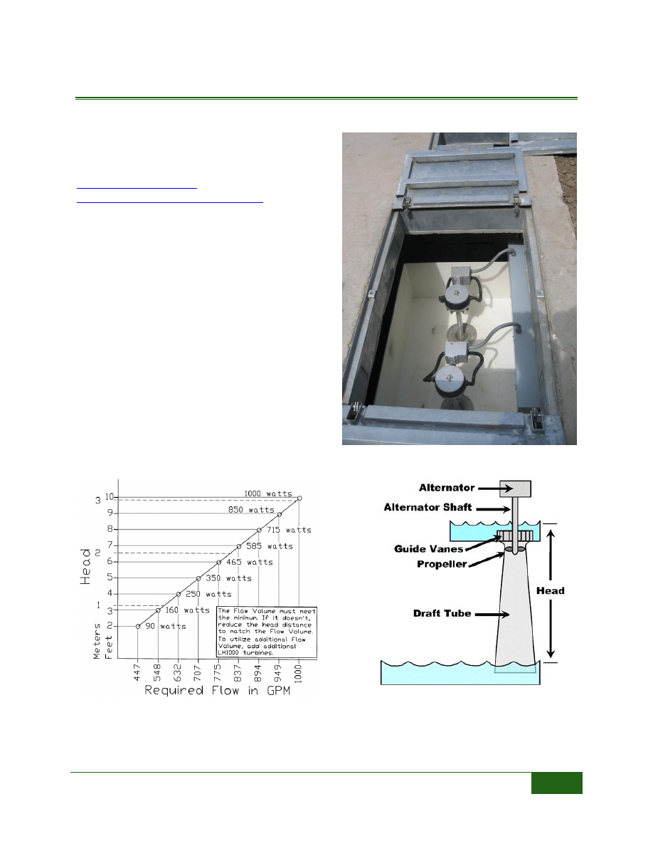
The LH1000 is a small propellor type turbine
suitable for sites with about 2 cfs, and 10 feet of
head. In these conditions one unit will produce 1
kW of DC electricity. The LH1000 uses a
permanent magenet alternator. An inverter is
utilized for AC systems, and the turbine can be
also be used to directly to charge batteries using
a charge controller. This turbine can be
purchased for between $3,000 and $4,000.
FIGURE 9: TWO LH1000 TURBINES INSTALLED IN
A VAULT (ES&D, 2010)
FIGURE 10: RANGE OF OPERATION
(WWW.ABSAK.COM)
FIGURE 11: BASIC COMPONENTS
(WWW.ABSAK.COM)
Low Head Turbines | Reaction Propeller Type Turbines (Small)
12
POWER PAL
2-416 Dallas Road
Victoria, BC V8V 1A9
CANADA
1-250-361-4348
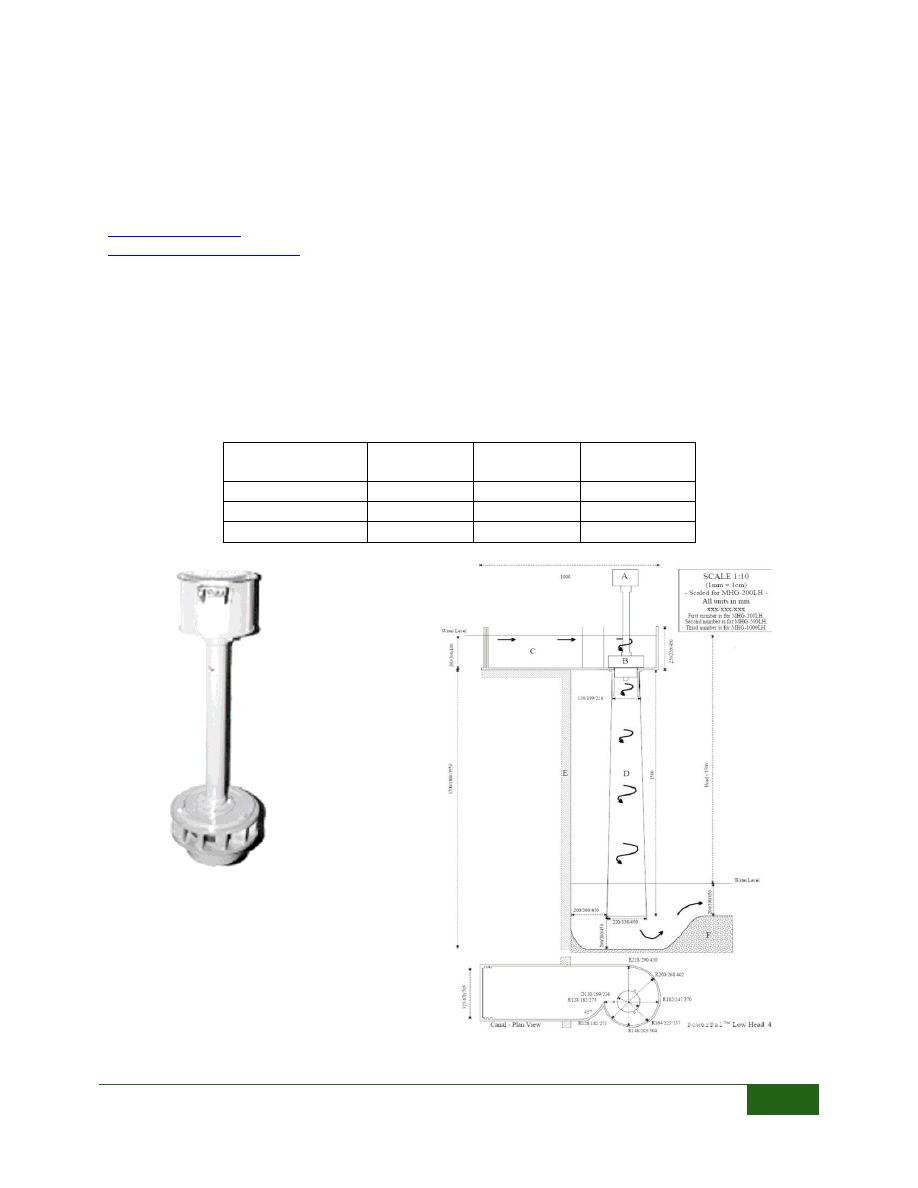
The Power Pal turbine is a very small, low head propellor type tubine that can produce up to 1 kW
of electricity. Three models are offered, producing 200, 500 and 1,000 Watts. The turbine is set at
the elevation of the incoming water and a draft tube extending below the turbine creates the head
differential with suction. At the combination of head and flow shown in the table below, each model
will produce the amount of power listed. This turbine is generally used for a stand alone
application, either a direct load or a battery charge. Grid connection of this type of turbine would
require additional equipment.
Power Pal
MGH-
200LH
MGH-
500LH
MHG-
1000LH
Flow (cfs)
1.23
2.47
4.6
Head (ft)
5
5
5
Power (KW)
0.2
0.5
1
FIGURE 12: POWER PAL
FIGURE 13: POWER PAL SCHEMATIC
Low Head Turbines | Reaction Propeller Type Turbines (Medium)
13
REACTION PROPELLER TYPE TURBINES (MEDIUM)
CANYON HYDRO – KAPLAN TURBINE
5500 Blue Heron Lane
Demming, WA 98244
1-360-592-5552
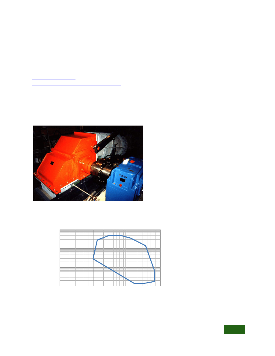
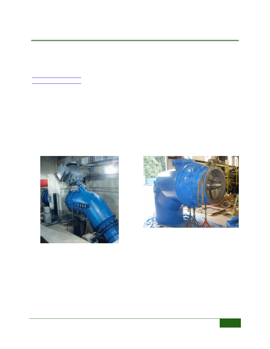
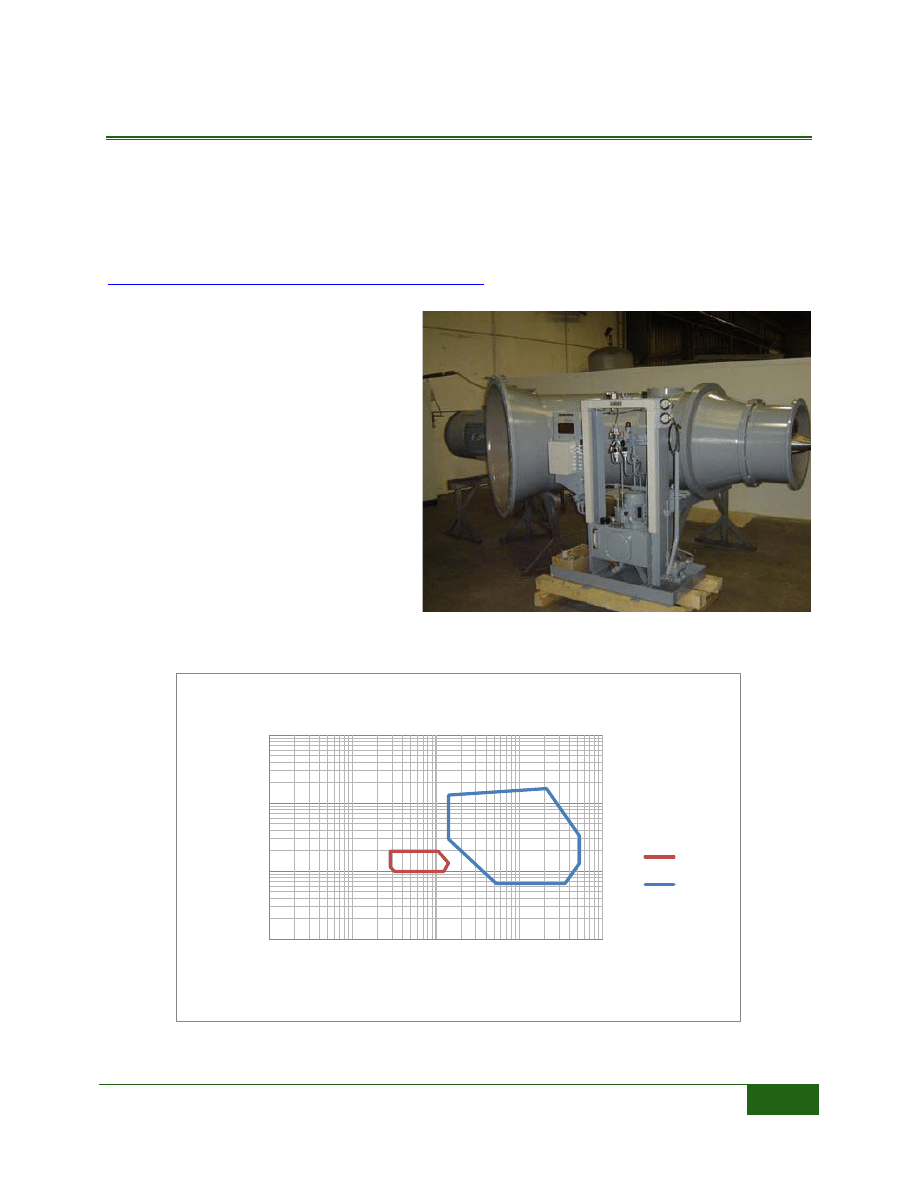
Canyon Hydro is located in Washington State and has been in business for over 30 years. Canyon
Hydro builds custom hydroelectric systems, including design and manufacturing the turbine, and
assembling the system to provide a “Water-to-Wire” package. A wide range of turbines are available
for both high and low head, large and small projects. For low head applications Canyon Hydro
suggests their Kaplan turbine based equipment package. The Kaplan turbine design adjusts to
varying head and varying flow using adjustable pitch runner blades and wicket gates. The efficiency
of the turbine is maintained down to about 35% of the design flow. This turbine is recommended
for sites with between 30 and 50 feet and flows ranging from 100 to 400 cfs. The turbine package
would be custom designed to the site conditions including the alignment of the intake and
discharge.
FIGURE 14: 300 KW KAPLAN TURBINE
INSTALLED IN LOGAN, UTAH
FIGURE 15: CANYON HYDRO KAPLAN TURBINE
Low Head Turbines | Reaction Propeller Type Turbines (Medium)
14
TOSHIBA INTERNATIONAL – HYDRO-EKIDS
18 Bayberry Drive
East Hampton, MA 01027
303-568-3881
www.tic.toshiba.com.au/hydro-ekids__8482_
The
Hydro-eKIDS
are
manufactured
in
three
standard sizes, S, M and L.
The runners can be chosen
from three alternatives to
match the site conditions.
The runner vane angle will
also be adjusted to match site
conditions. These turbines
can be installed in series or in
parallel to accomidate a
range of head and flow
conditions.
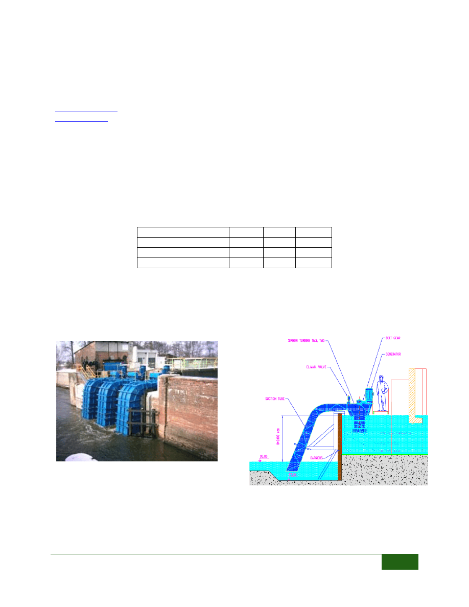
These are propellor type turbines and would be best suited for installation in an existing pipe or in
an outlet of a reservoir. The Type S produces between 5 and 35 kW, the Type M between 5 and 100
kW, and the Type L between 10 and 200 kW. Toshiba provides the turbine, generator and controls
in one package for this type of turbine. As seen in Figure 17, the turbine can be installed with a
siphon intake so not to distrurb the existing dam.
FIGURE 16: RANGE OF SITE CONDITIONS
1
10
100
1
10
100
1000
H
e
ad
(ft
)
Discharge (cfs)
Toshiba HYDRO-eKIDS
S
M
L
FIGURE 18: TYPE M (WWW.TIC.TOSHIBA.COM.AU)
FIGURE 17: EXAMPLE INSTALLATION WITH
SIPHON INTAKE
Low Head Turbines | Reaction Propeller Type Turbines (Medium)
15
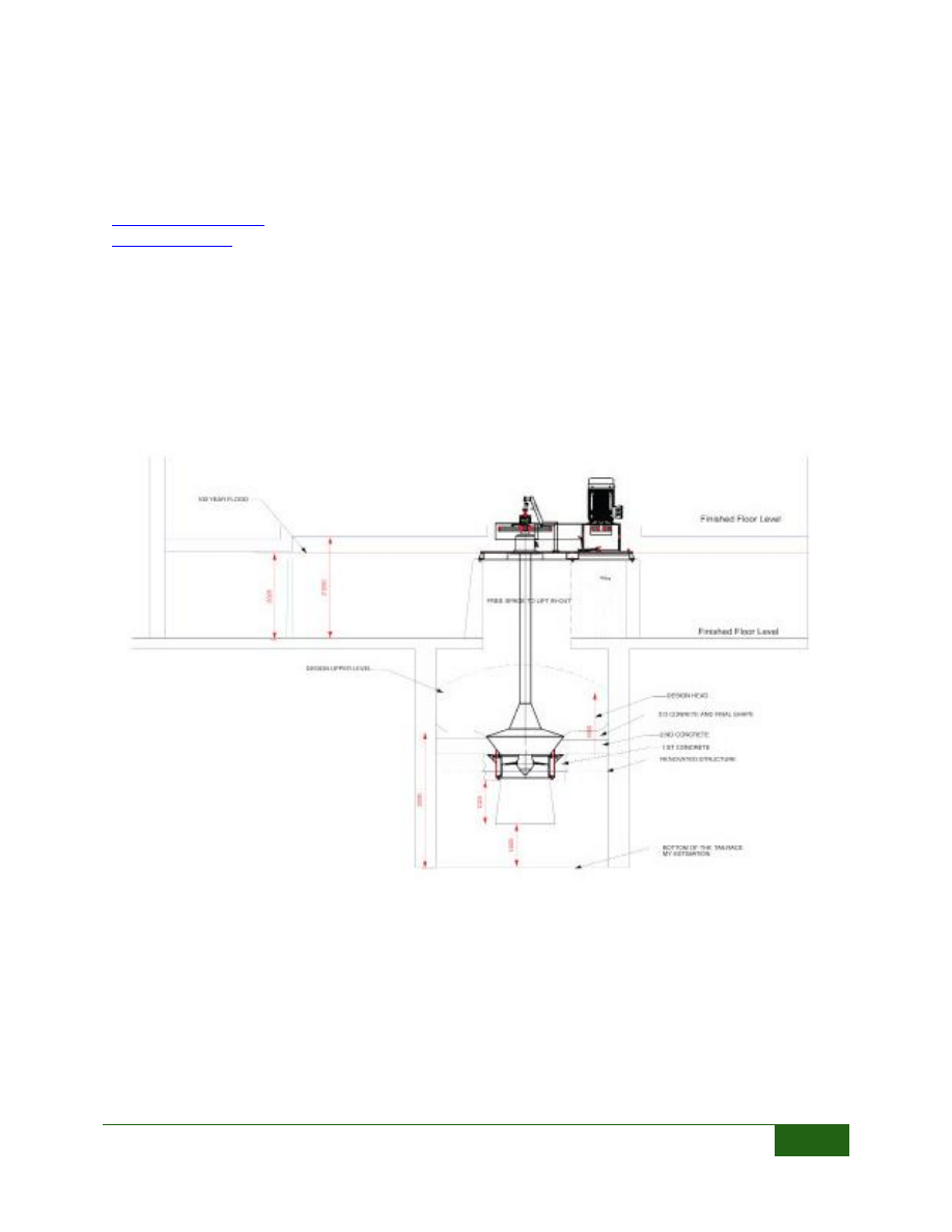
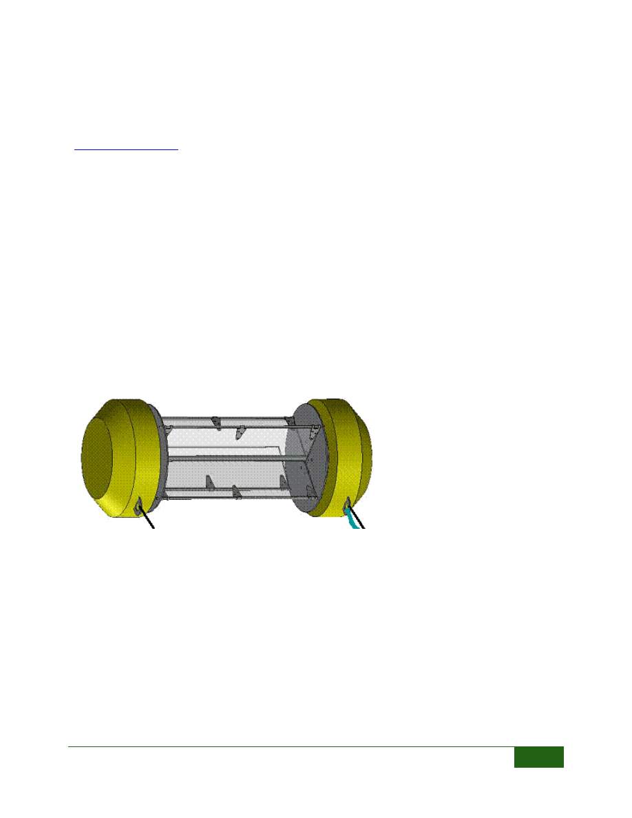
VERY LOW HEAD TURBINE
4 rue de la Megisserie
12100 Millau (France)
00 33 565-599-946
This turbine is in the pilot project stage of
development. A turbine has been installed in a
site in France. The company is eager to expand
its buisiness into the United States. The turbine
will be offered in five sizes to accomidate a
range of site conditions. This turbine is
intended to be installed in an open channel,
and a head differential will be created across
the turbine. This turbine would probably be
best suited for the larger canals in Colorado,
and in an existing structure to reduce the
infrastructure costs. At the maximum
discharge rate shown below this turbine
operates at almost 80% efficiency.
Maximum discharge through the turbine at
the specified head
Runner Diameter (feet)
N
e
t
H
e
ad
(
fee
t)
11.6 13.1 14.8 16.4 18.4
4.6
367
470
593
731
918
4.9
381
484
614
756
950
5.2
396
501
632
780
982
5.6
406
516
653
805
1010
5.9
417
530
671
830
1042
6.2
431
544
689
851
1070
6.6
441
558
706
872
1095
6.9
452
572
720
897
7.2
463
586
742
918
7.5
473
600
759
936
7.9
484
614
777
8.2
491
625
791
8.5
501
639
809
8.9
512
650
823
9.2
523
660
9.5
530
675
9.8
540
685
10.2 547
696
10.5 558
706
Power Produced (kW)
Runner Diameter (feet)
N
e
t
H
e
ad
(
fee
t)
11.6 13.1 14.8 16.4 18.4
4.6
113
144
182
226
284
4.9
125
159
202
251
315
5.2
138
175
223
276
347
5.6
151
192
244
302
380
5.9
164
209
266
329
415
6.2
178
227
288
357
450
6.6
192
245
311
386
486
6.9
207
264
335
415
7.2
222
283
359
445
7.5
237
302
384
476
7.9
253
322
409
8.2
269
343
435
8.5
285
363
462
8.9
302
385
488
9.2
318
406
9.5
336
428
9.8
353
450
10.2 371
473
10.5 387
496
FIGURE 19: VLH TURBINE INSTALLATION
(WWW.VLH-TURBINE.COM)
Low Head Turbines | Reaction Propeller Type Turbines (Medium)
16
GILKES – KAPLAN TURBINE
2103 – 4464 Markham Street
Victoria, BC V8Z 7X8
250-483-3883
Gilkes is a British company with a distributor in Canada. They manufacter both high and low head
turbines, for small and large hydro applications. The company has been in existance since 1856.
Gilkes manufactuers a small scale Kaplan turbine that may be installed in a drop structure. More
details about this turbine were unavailable at the time this report was published. We suggest
contacting the distributor to see if this turbine would be appropriate for a site. This turbine is
supplied with a head level sensor to optimize power production at a range of flow rates. A
hydraulically managed control system together with PLC controls enables the turbine to start-up,
synchronise and shut down automatically.
FIGURE 20: GILKES SMALL KAPLAN TURBINE
Low Head Turbines | Reaction Propeller Type Turbines (Medium)
17
MAVEL
121 Mount Vernon Street
Boston, MA 02108
617-242-2204
Mavel is a turbine manufacturer located in the Czech Republic, with a distributor in Massachusetts.
The company recently announced a Micro Line of turbines for low head projects. They have
successfully installed these turbines in Poland, Japan, and Latvia. Mavel has installed turbines in the
United States, but not turbines from the Micro Line. The Mavel Micro Turbines are a propellor type
turbine designed for low head, low flow site conditions. Currently three sizes of the turbine is
offered, the TM3, TM5 and TM10. The range of site conditions suitable for each turbine is listed in
the table below. These turbines can be installed in parallel if there is more flow available than a
single turbine can handle, as shown in the photograph below.
TM3
TM5
TM10
Head (ft)
5-20
5-20
7-16
Flow (cfs)
5-14
25-50 70-175
Power Output (kW)
0.7-13 2-50
30-180
The siphon outlet on these turbines may be beneficial if there is an exisitng structure that needs to
be bridged. Installing the siphon outlet may decrease installation costs if modifying the existing
structure is not feasible.
FIGURE 21: TM10 INSTALLATION
(WWW.MAVEL.CZ)
FIGURE 22: EXAMPLE INSTALLATION
Low Head Turbines | Reaction Propeller Type Turbines (Large)
18
REACTION PROPELLER TYPE TURBINES (LARGE)
VOITH HYDRO
760 East Berlin Road
York, PA 17408-8701
717-792-7000
Info.voithhydro@voith.com
www.us.voithhydro.com/vh_en_pas_small_hydro.htm
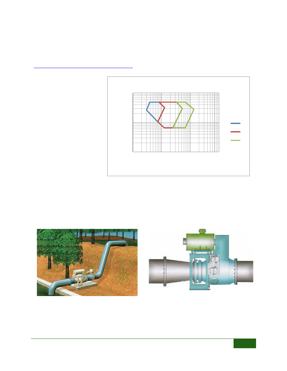
Voith Hydro is one of the major
manufacturers of large hydro turbines in
the world. They also manufacturer a line
of small hydro turbines including a low
head Kaplan turbine. The Kaplan turbines
can be manufactured with 3 to 7 blade
runners of any diameter, in vertical full or
semi spiral arrangements. Voith offers
multiple configurations including pit
turbines, S-turbines, bulb turbines, and
tubular axial turbines.
Voith also offers an “Ecoflow” turbine
with much lower head and flow
requirements. These turbines can produce
between 25 and 175kW and are designed
to integrate into existing structures.
FIGURE 24: RANGE OF SITE CONDITIONS
1
10
100
1000
1
10
100
1000
10000
He
ad
(
ft
)
Discharge (cfs)
Voith Hydro
Ecoflow
Kaplan
FIGURE 23: ECOFLOW TURBINE (WWW.KOESSLER.COM)
Low Head Turbines | Reaction Propeller Type Turbines (Large)
19
ANDRITZ HYDRO
Jeans Pautz
ANDRITZ HYDRO GmbH
Penzinger Strasse 76
1141 Vienna, Austria
+43 (1)891 00 0
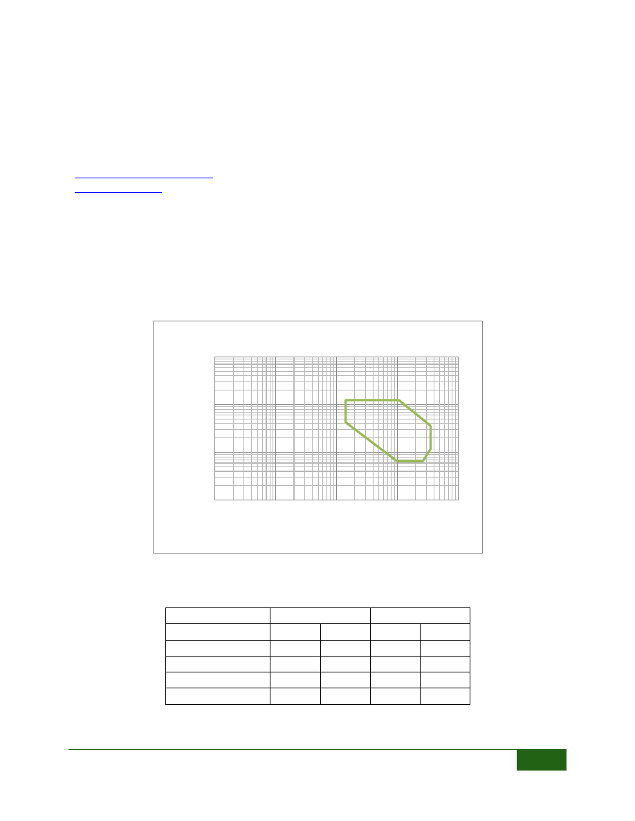
Andritz Hydro is an Austrian company that has installations worldwide, including in the United
States. They have a compact turbine line that would be suitable for Colorado’s irrigation canals.
These turbines require less infrastructure than Andritz’s larger traditional turbines. The head and
flow range of the low head Axial turbine is shown in the chart below. In the low head range of 5-30
feet this turbine would require at least 200 cfs to operate. These turbines would be best suited for
the largest canals in Colorado, with the ability to utilize up to 3,500 cfs at 20-40 feet of head. Andritz
also has a large line of hydro turbines, generally using more than 3,500 cfs.
FIGURE 25: RANGE OF SITE CONDITIONS
The specific turbines can operate in the following ranges.
Turbine Type
Head (ft)
Flow (cfs)
Belt Drive Bulb
6.6
15.6
212
883
Bevel Gear Bulb
6.6
39.4
80
1625
Axial
19.7
98.4
80
2295
Kaplan
6.6
39.4
141
2119
Eco-bulb
6.6
49.2
529
3531
1
10
100
1000
1
10
100
1000
10000
H
e
ad
(ft
)
Discharge (cfs)
Andritz Hydro Turbines
Low Head Turbines | Hydroengine
20
HYDROENGINE
NATEL ENERGY
2175 Monarch Street
Alameda, CA 94501
501-984-3639
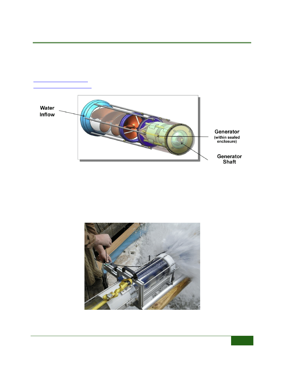
Natel Energy’s hydroengine is a unique design using the uplift created as water passes by curved
blades. This turbine is in the pilot project stage, and is ready for commercial development. A 10 kW
turbine was recently installed in an irrigation canal in Buckeye, Arizona. The turbine was installed
in an aging check structure that needed repair. These turbines will be offered in 5 sizes with the
following site conditions and power productions. The power produced is at the high end of the flow
range and at 13 feet of head.
Model
Head (ft)
Flow (cfs)
Power (kW)
SLH-10
3.3
19.7
15
37
32
SLH-50
3.3
19.7
63
155
133
SLH-100
3.3
19.7
127
310
266
SLH-200
3.3
19.7
253
620
533
SLH-500
3.3
19.7
633
1550
1332
The turbine is offered as a water-to-wire package including the turbine and draft tube, generator,
switchgear, SCADA compliant controls, as well as installation and maintenance support. This
system is intended to be installed in an existing drop or structure, requiring little civil
improvements. This system is referred to as a hydraulic engine instead of a hydraulic turbine,
because of the unique design, claimed to be the first fully flooded two-stage water impulse engine.
This design is fish friendly, allowing fish and debris to pass through the engine without damage.
FIGURE 26: CROSS SECTION OF
THE HYDROENGINE
(WWW.NATELENERGY.COM)
FIGURE 27: PILOT INSTALLATION
IN BUCKEYE, AZ
(WWW.NATELENERGY.COM)
Low Head Turbines | Screw Type Turbines
21
SCREW TYPE TURBINES
HYDROCOIL POWER
1359 Arbordale Road, 3
rd
floor
Wynnewood, PA 19041
862-397-4363
The HydroCoil Turbine is a very small turbine that can utilize heads between 10 and 70 feet of head,
and produce up to 2 kW of electricity. The turbine is in the funding stage and ready for
commercialization. Certified testing occurred on a prototype and using 12 feet of head generated
approximately 1.5 kW using 1.8 cfs. These turbines could be installed in “clusters” utilizing higher
flow rates, or in series to utilize longer drops. Although this turbine is not yet commercially
available, the manufacturer could be contacted to discuss your project and application for the
turbine.
FIGURE 28: HYDROCOIL IN USE
(WWW.HYDROCOILPOWER.COM)
Low Head Turbines | Screw Type Turbines
22
RITZ-ATRO – HYDRODYNAMIC SCREW TURBINE
Ritz-Atro GmbH
Max – Brod – Strabe 2
D-90471 Nurnberg, Germany
+49 911 998 12 -0
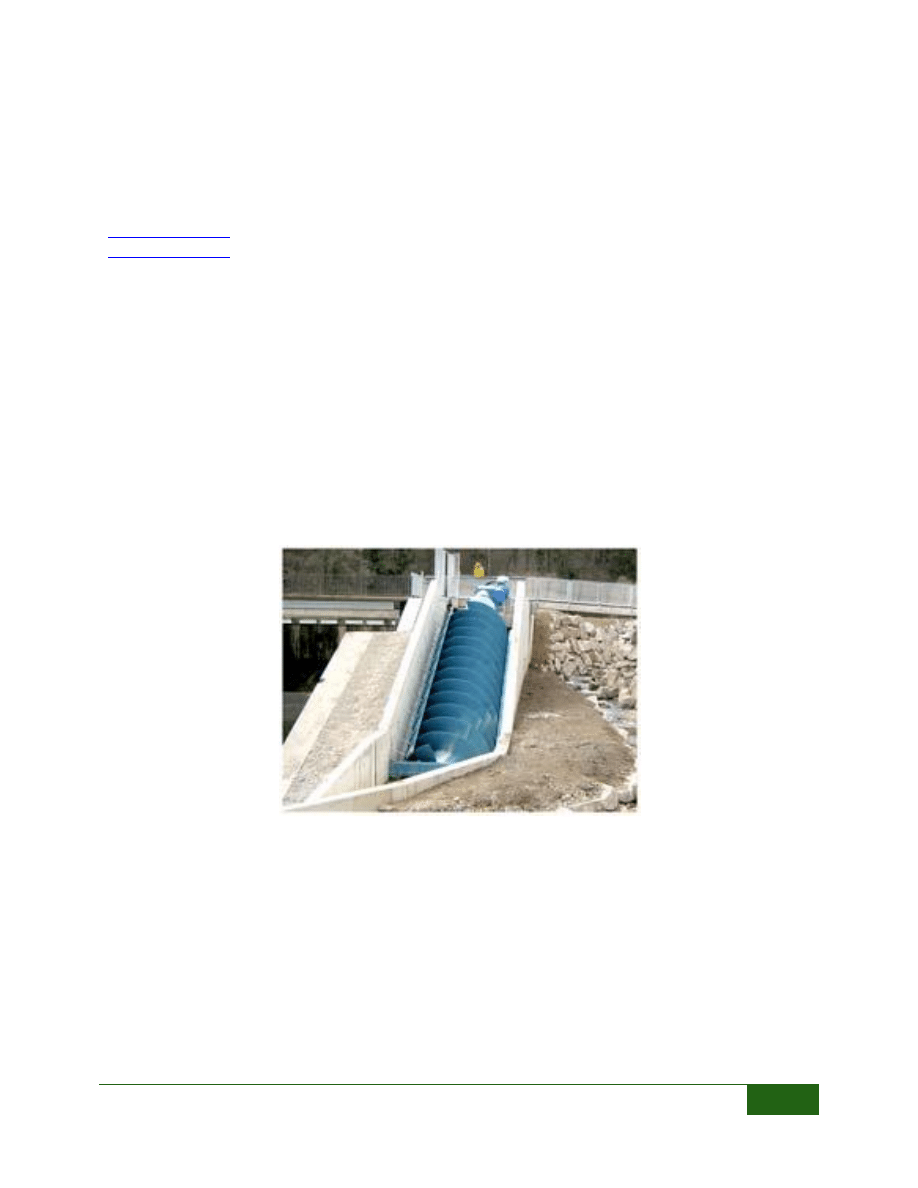
Ritz-Atro is a German Company that supplies pumps to the water and wastewater community,
specializing in Archimedean screw pumps. As a result they also manufacturer “hydrodynamic
screws”, which are turbines based on the Archimedean screw principle. These turbines are fish
friendly and do not require fine screening. These turbines also maintain their efficiency over
varying heads and flow rates. Eighty percent of peak efficiency is maintained down to 30% of the
design flow rate, and it can operate at as low as 5% of the design flow rate. Turbines are supplied in
many sizes and custom designed for each site. They can produce up to 300 kW of power, using up to
200 cfs, and heads up to 33 feet.
There are a number of distributers and installation in the United Kingdom. It appears that some of
these distributers are also interested in entering the U.S. market. This turbine could be used in
existing concrete structures with a unique geometry, as seen in the photograph below.
FIGURE 29: HYDRODYNAMIC SCREW (WWW.RITZ-ATRO.DE)
Low Head Turbines | Waterwheels
23
WATERWHEELS
HYDROWATT
Am Hafen 5
76189 Karlsruhe, Germany
+49 (0)721-831 86-0
http://www.hydrowatt.de/sites/english/home.html
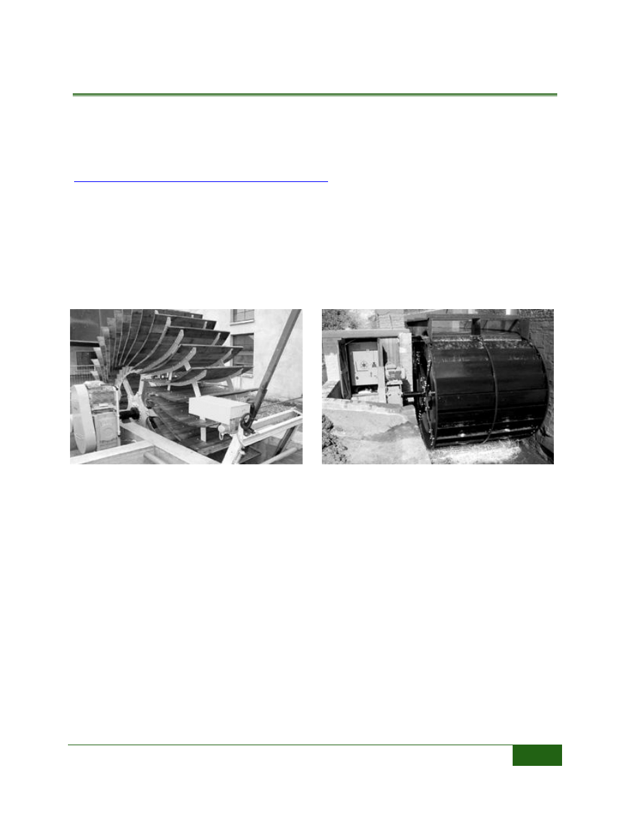
Hydrowatt of Germany, manufacturers both overshot and breastshot waterwheels. The water
enters an overshot waterwheel at the 12 o’clock position, and can be used at sites with heads
between 8 and 32 feet, and flows between 3.5 and 88 cfs. The water enters a breastshot waterwheel
below the axis, and can use between 3 and 10 feet of head and between 18 and 250 cfs of flow.
These traditional waterwheels could be used in a location where a waterwheel was once installed,
to recreate the historic site while producing electricity with a modern wheel and generator. These
turbines have an efficiency around 60% which is much lower than a Kaplan turbine, but the site
conditions may make these types of turbines an economical alternative.
FIGURE 31: OVERSHOT WATERWHEEL
(WWW.HYDROWATT.DE)
FIGURE 30: BREASTSHOT WATERWHEEL
(WWW.HYDROWATT.DE)
Low Head Turbines | Hydrokinetic
24
HYDROKINETIC
ALTERNATIVE HYDRO SOLUTIONS – DARRIEUS WATER TURBINE
Stephen Gregory
Suite 421 323 Richmond Street East
Toronto, Ontario M5A 4S7
416-368-5813
sdgregory@althydrosolutions.com
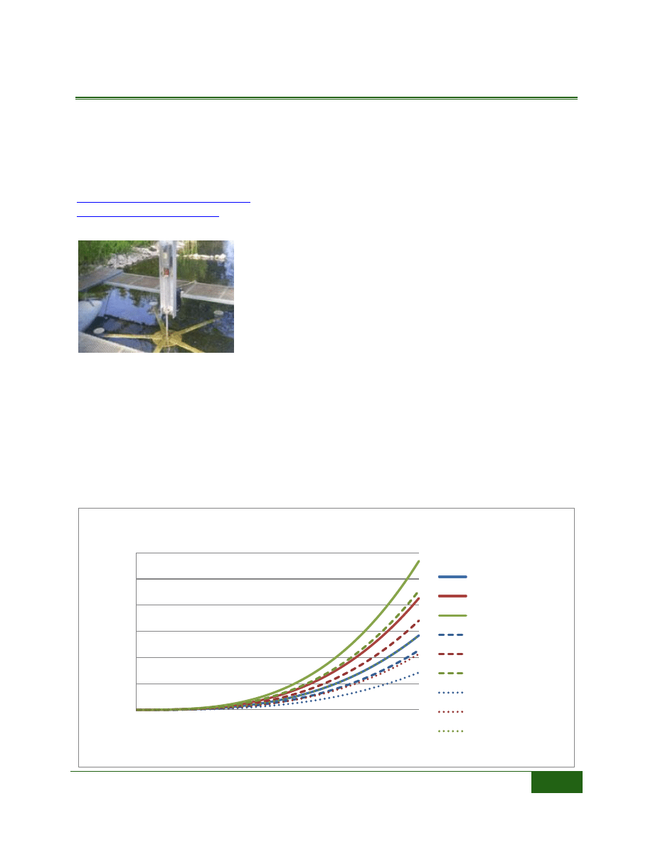
These Darrieus Water Turbines are manufactured in Canada, with
one installation in the United States. This turbine is considered a
hydrokinetic turbine that uses the velocity of the passing water to
produce power and requires no head differential. Generally
speaking this turbine can be installed in a canal with a water
depth of over 2 feet and with water velocity of more than 2.5 feet
per second. Each turbine is custom designed to the site’s
conditions and can produce between 1 and 4 kW of electricity.
The turbine is suspended in the water with a barge or a structure
crossing the canal. The turbine rotates on a vertical axis to turn a
generator located above the water surface. Below is a curve of expected power given the turbine’s
diameter and the depth of water the turbine is submerged in.
Colorado’s irrigation canals generally would not meet the criteria of depth and velocity that is
needed to produce power with these turbines, although conditions may exist at drop structures or
areas where the canal width is narrower. Trash accumulation may be an issue with these turbines,
therefore screening upstream may be required.
0
0.5
1
1.5
2
2.5
3
0
1
2
3
4
5
6
Pow
e
r
(k
W)
Water Velocity (ft/sec)
Darrieus Turbine Power Output
10 ft dia, 2 feet depth
10 ft dia, 3 foot depth
10 ft dia, 4 feet depth
8 ft dia, 2 ft depth
8 ft dia, 3 ft depth
8 ft dia, 4 ft depth
5 ft dia, 2 ft depth
5 ft dia, 3 ft depth
5 ft dia, 4 ft depth
FIGURE 32: DARRIUS WATER
TURBINE
Low Head Turbines | Hydrokinetic
25
HYDROVOLTS
210 South Hudson Street #330
Seattle, WA 98134
206-658-4380
The Hydrovolts turbine is in the pre development stage. They have tested one turbine in an
irrigation canal in Oregon. This turbine is “dropped in” to the canal and suspended using cables
attached to either bank. The turbine rotates on a horizontal axis with the generator located on the
ends of the turbine underwater. No modifications to the canal or additional structures are required
to deploy this technology. The company will be producing three sizes of turbines, the middle size is
rated at 5kW and will cost about $20,000, the larger size is 25kW and will cost about $50,000. Both
models are rated for 6.5 feet/second water velocity. At this velocity the water holds about 0.4 kW
per square foot; to produce 5 kW the turbine will need to cover at least 12.5 square feet of flow
area. This 5kW turbine may be approximately 7 feet wide and 2 feet in diameter.
Velocities over 6.5 feet/second will only be seen in an irrigation canal in certain situations, such as
below drops or chutes. Hydrokinetic technologies like this are feasible in canals with high
velocities, but they will only be able to produce a small amount of power. They will likely be useful
in situations where the power can be consumed at the turbine site, such as powering automation
equipment or remote pumping locations.
FIGURE 33: SCHEMATIC OF HYDROVOLTS TURBINE
(WWW.HYDROVOLTS.COM)
Low Head Turbines | Do-It-Yourself Turbines
26
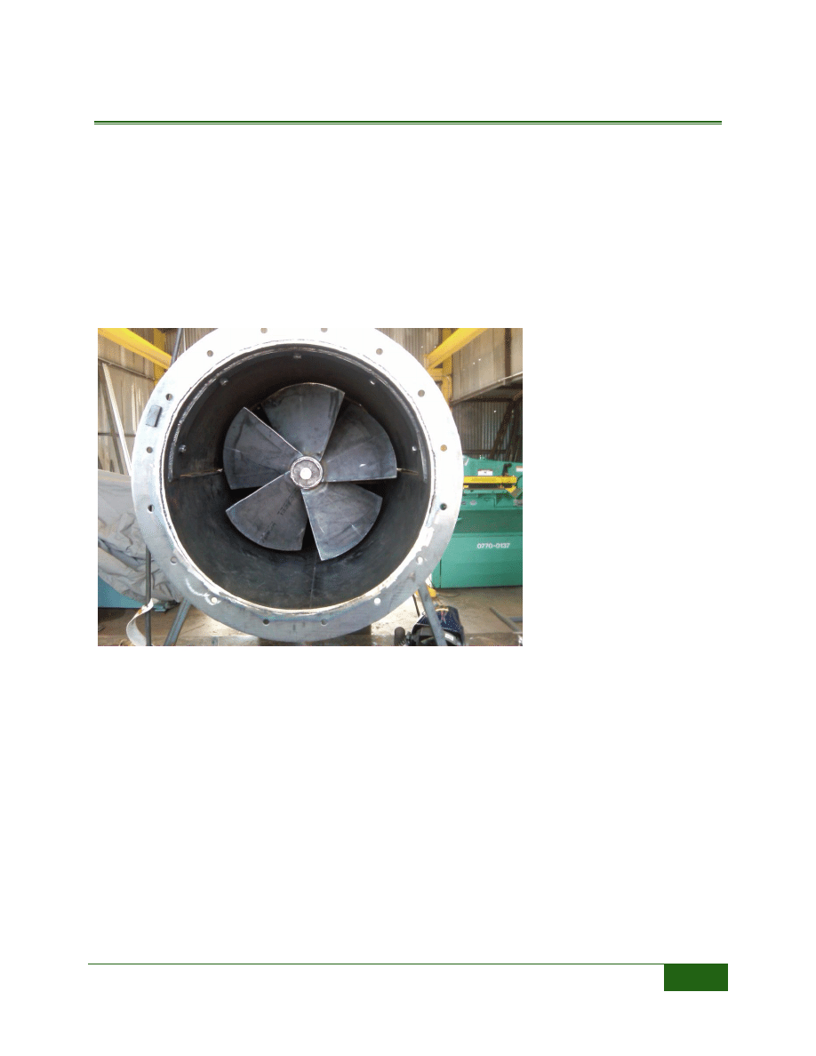
DO-IT-YOURSELF TURBINES
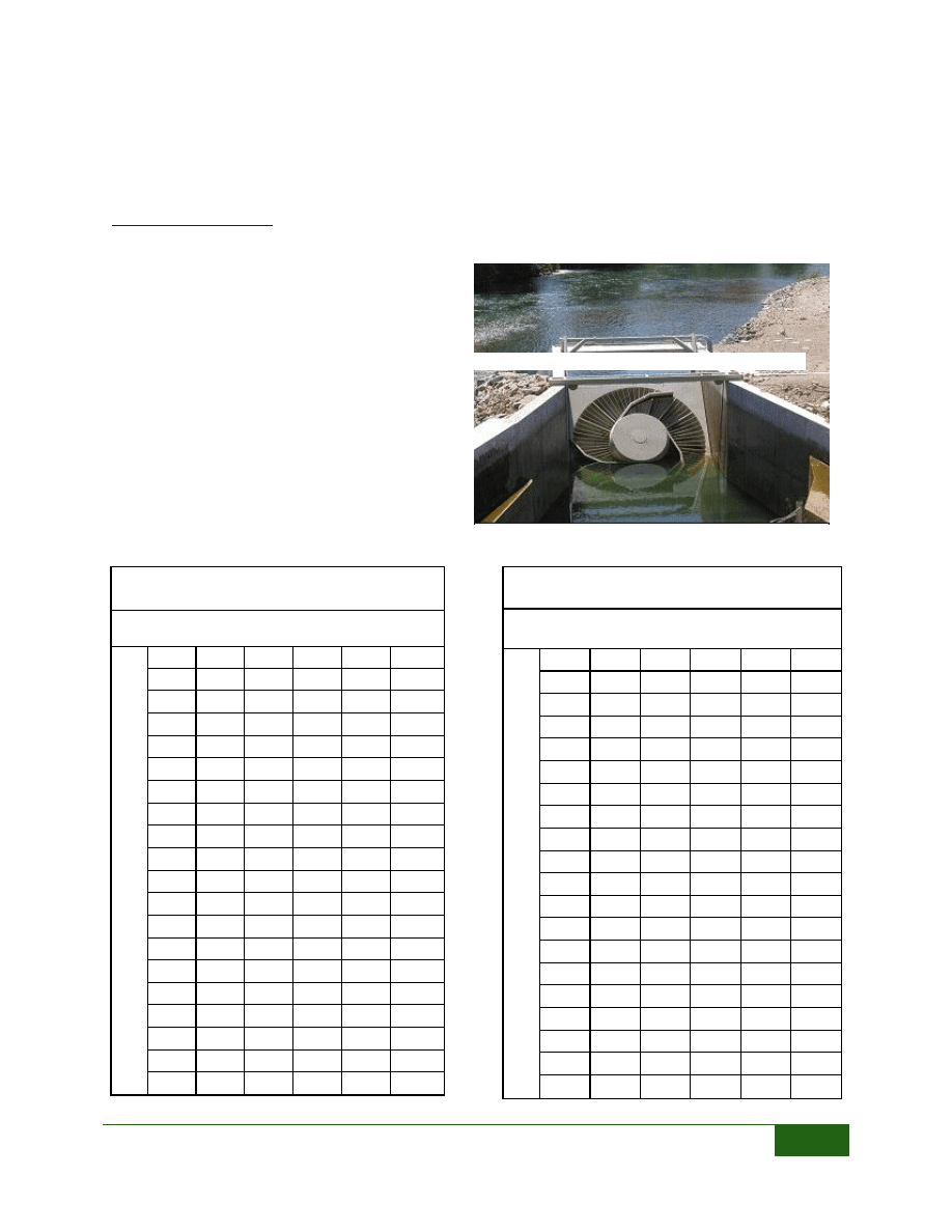
ELEPHANT BUTTE IRRIGATION DISTRICT
Las Cruses, NM
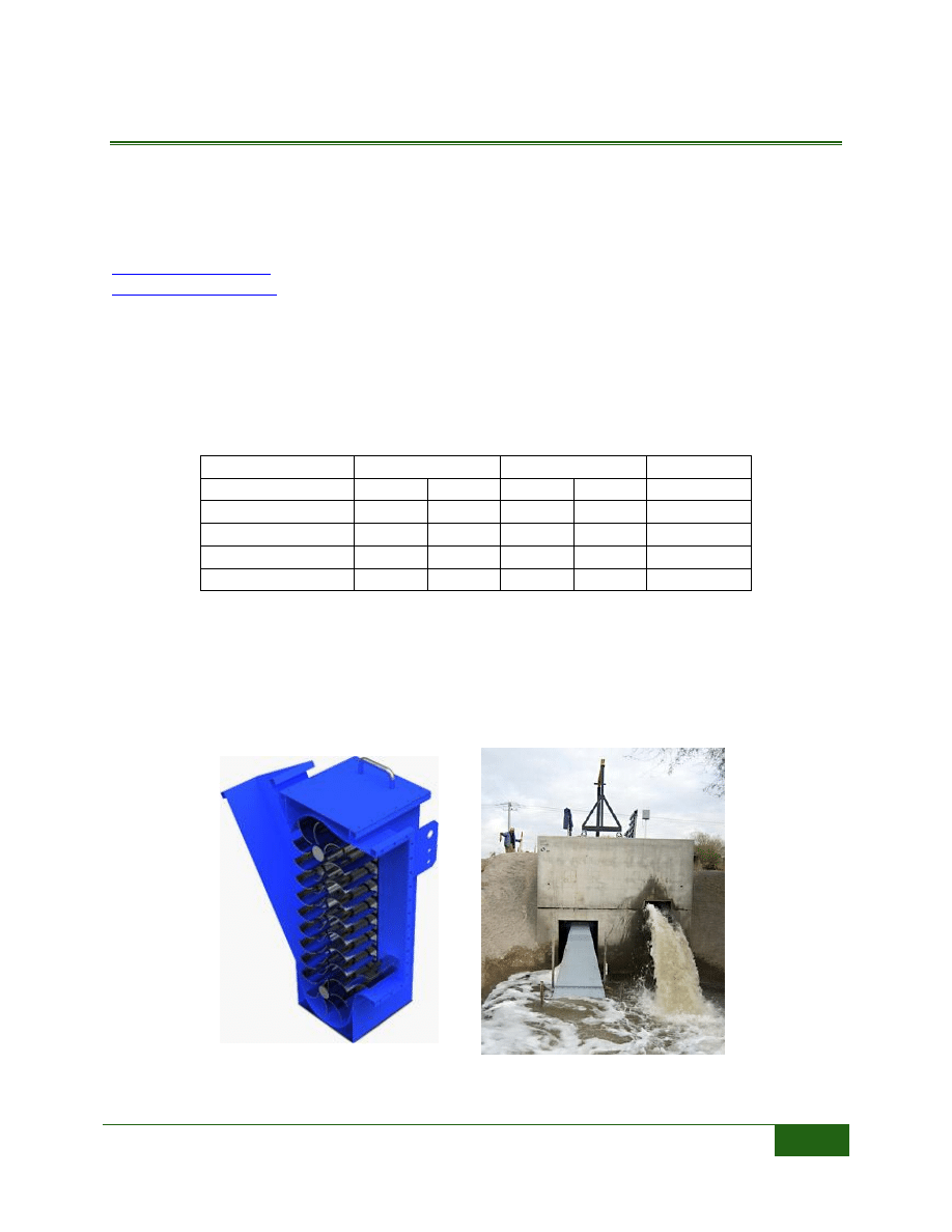
The staff of the Elephant Butte Irrigation district designed, manufactured and installed a turbine in
a drain off of their canal with 8 feet of head and about 20 cfs of flow. The irrigation district designed
and tested four turbine configurations before finalizing the design. They started with a paddlewheel
style turbine, moved on to an axial flow propeller type, and modified the blades to optimize the
power production. The final turbine design is shown in the photograph below. They also have
optimized their generator choice and are now producing about 6 kW of electricity.
The District has identified
over 100 sites on the system
where this type of turbine
could
be
installed.
By
designing and manufacturing
their own turbines, they are
able to save a significant
amount of cost. The efficiency
of the turbine is not as high
as
the
other
turbines
presented in this report, but
the cost is much lower and
with multiple sites the total
power produced could be as
high as 1.5 MW.
FIGURE 34: EBID KAPLAN STYLE TURBINE
Low Head Turbines | Do-It-Yourself Turbines
27
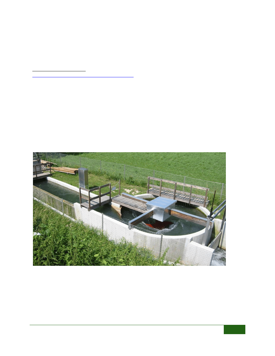
WATER VORTEX POWER PLANT
A-3200 Obergrafendorf
Wildgansstraße 5
AUSTRIA
Telephone: 0043-(0)2747-3106
office@zotloeterer.com
http://www.zotloeterer.com/our_company.php
The gravitational water vortex power plant was invented by an Austrian engineer, Franz Zotlöterer.
This power plant uses the rotational energy at the center of a vortex to turn a paddle type turbine.
There have been installations in Switzerland, Indonesia, and currently an installation is in progress
here in Colorado. The plant requires a very small head difference, and the configuration is very
unique. The turbine is set in the center of the vortex with the axis of rotation vertical, and the
generator is mounted above the water. The diameter of the spinning pool, quantity of flow and head
drop is used to determine the amount of power that can be produced at a site. For example, the
power plant shown in the figure below utilizes 4.6’ of head, 30 cfs of flow, and the spinning pool is
18 feet in diameter. This plant can produce 7.5 kW of electricity.
FIGURE 35: INSTALLATION IN SWITZERLAND (WWW.ZOTLOETERER.COM)
Wyszukiwarka
Podobne podstrony:
Interim Report Executive Summary
Interim Report By Task Force Updated From 12th nov 2004
Interim Report 1
Interim report 12 mth Chi Shing ES eng 20131121 c
INTERIM REPORT OF THE INTERAGENCY OCEAN POLICY TASK FORCE
(IV)A Preliminary Report on the Use of the McKenzie Protocol versus Williams Protocol in the Treatme
Course hydro pl 1
PNADD523 USAID SARi Report id 3 Nieznany
Hydro w1
Biochemia TZ wyklad 12 integracja metabolizmu low
Microactuator for Precise Head Positioning
hydro x car
baker Is Head Movement Still Needed for Noun Incorporation
hydro id 207614 Nieznany
EXTERIOR AND INTERIOR TRIM
więcej podobnych podstron