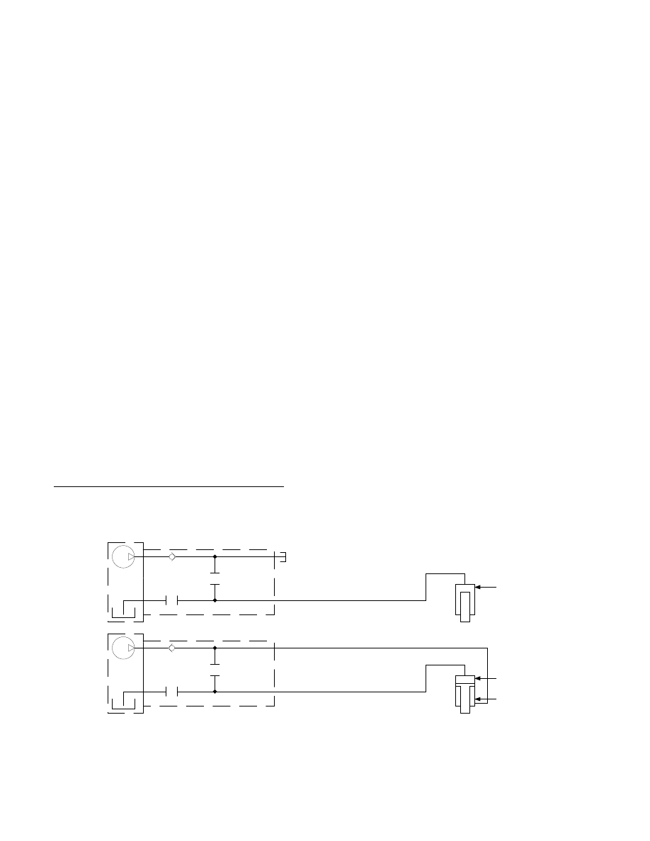
VALVE
RETRACT
VALVE
EXTEND
Single Acting Jacks
CAP END
VALVE
RETRACT
VALVE
EXTEND
Double Acting Jacks
CAP END
Figure 1
ROD END
LANDING GEAR
1. GENERAL INFORMATION
Landing gear systems are available for fifth wheel and tag style trailers. Most of the systems consist of two
jacks but there are single jack systems available. The jacks are available as single-acting (power down with
spring return) or double-acting (power down-power up). The landing gear jacks are available in the
following capacities and strokes:
Single-acting jacks
6,000# x 14” stroke (tag style trailers only)
6,000# x 21” stroke
10,000# x 21” stroke
Double-acting jacks 7,000# x 21” stroke
12,000# x 21” stroke
12,000# x 24” stroke
12,000# x 30” stroke
24,000# x 24” stroke
The landing gear jacks can be operated individually with a control valve arrangement for each jack or
operated at the same time with one control valve arrangement for both jacks. The single control valve
system allows the jacks to lift together but does not allow individual control of the jacks. With the
individual control valve arrangement, the jacks can be operated either way. Most systems presently used
have a control valve arrangement for each jack.
There are two basic types of control valve systems. There are the hydraulic switch systems, the control
valves are lever operated and systems controlled with an electronic switch that controls electric solenoid
valves. The newer style systems, including the hydraulic switch controls, will accommodate either single or
double-acting jacks. Some of the older systems, especially the older lever controlled systems, would only
work with single-acting jacks. The new hydraulic switch control systems have an auxiliary hand pump
which is optional with the electric switch controlled systems. The landing gear systems with double-acting
jacks use a regenerative hydraulic circuit. For a detailed explanation of the regenerative circuit see
ML37939 “Regenerative Hydraulic Circuits” under “Advanced Hydraulic Theory” in the HWH Online
Technical School. The following simple schematics will show how the same hydraulic circuit can be used
to operate either singe or double-acting jacks.
Some equipment used with landing gear systems is designed specifically for non-motorized vehicles
and is not compatible with motorized vehicles. It is important the correct equipment is used when
installing or repairing systems.
H
UNDERSTAND OPERATOR’S MANUAL BEFORE
TIRES OR CRAWLING UNDER VEHICLE.
USING. BLOCK FRAME AND TIRES BEFORE REMOVING
HWH HYDRAULIC LEVELING
STORE
EXTEND
WARNING
LEVELING
CAUTION!
LR
L
W
CORPORATION
H
LF
5 AMP
FUSE
OFF
LEVEL
R
R
RF
RR
STORE
EXTEND
RF
LF
LF
PRESSURE
RETURN
RF
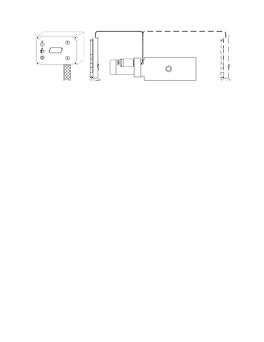
Figure 2
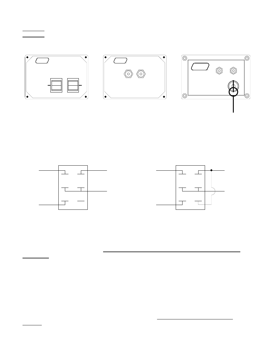
Figure 3
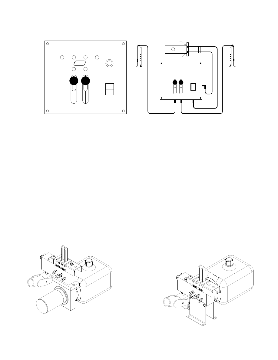
2. LANDING GEAR SYSTEMS WITH HYDRAULIC SWITCHES (LEVERS)
2-1 110 series lever controlled landing gear.
This was the very first control system for a landing gear system. This control system could only be used
with single acting jacks. It will probably be very rare to run into this system. The 110 series system is a two
lever valve with an integrated switch and light plate. Battery power is supplied to the rocker switch in the
light plate. With the rocker switch on, power is supplied to a small micro switch in the valve assembly.
When a lever is pushed to “EXTEND”, the micro switch contacts close, sending + voltage to the pump
relay coil. When the pump relay is turned on, the relay contacts supply + voltage to the pump motor. When
the pump motor is running, hydraulic pressure and flow is directed to the valve. The lever also depresses a
plunger which opens the extend valve for the jack. Fluid and pressure is directed to the jack, which extends
the jack. The jack will continue to extend until the control lever is released or the jack reaches full
extension. To retract the jack, the control lever is pushed to the “RETRACT” position. The lever depresses
a plunger which opens the retract valve for the jack. The pump does not run. The jack is equipped with
springs to pull the foot up and retract the cylinder. When pushing the levers to “EXTEND” or
“RETRACT”, the valves can be “feathered” to control the speed of extension or retraction. When extending
the jacks, it is best to push the levers to the full extend position so the pump motor does not labor
unnecessarily. The jacks with this system usually were equipped with jack down warning switches. The
light plate was wired differently than a 110 plate for motorized vehicles, this was so the warning light
package would only work if the panel rocker switch was on.
2-2 Hydraulic switch controlled landing gear with auxiliary hand pump.
X
R
E
T
E
T
LEFT SIDE JACK
LF
RIGHT SIDE JACK
RF
HOLD
PUSH AND
CONTROL
SWITCH
PUMP
Figure 4
This is the system that is presently being used when a lever controlled system is desired. The system works
with single or double-acting jacks. There is one control lever for each jack. Each lever has an “EXTEND”
and a “RETRACT” position. Moving the lever in either direction will depress a plunger which opens either
the extend or retract valve. When the system is equipped with an electric pump motor, the hydraulic switch
plate will have two toggle switches, one is an “ON/OFF” maintain switch the other is the pump control
switch. This is a momentary switch and must be held to the “ON” position to run the pump. Some early
systems have only the pump control switch. Battery + voltage is supplied to the “ON/OFF” switch. When
this switch is on, + voltage is supplied to the pump control switch. When the pump control switch is held to
the “ON” position, + voltage is supplied to the pump relay coil to turn the relay on. This supplies + voltage
to the pump motor causing the pump motor to run. If the system has no motor, the hand pump is used to
extend or with double-acting jacks, retract the landing gear jacks. Place the hydraulic switches in the
desired position, insert the pump handle and move the pump handle up and down. See section 4.
AUXILIARY HAND PUMP for a detailed explanation of the hand pump.
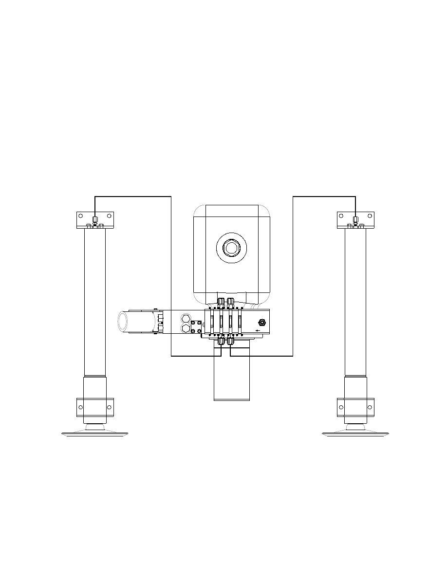
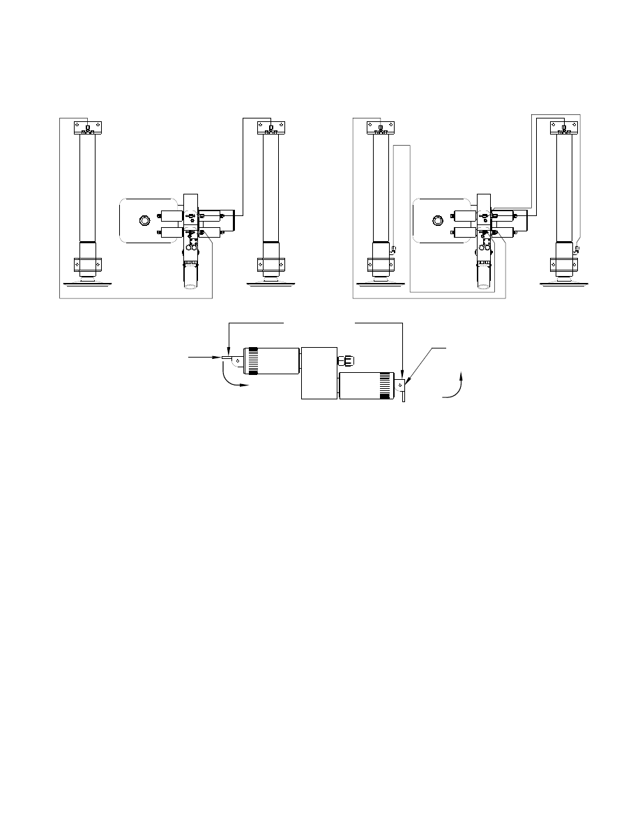
2-2.1 Hydraulic switch systems with single acting jacks.
With this system, there is only one hose to each jack. When the lever is pushed to the “EXTEND” position
and the pump is running, The extend valve directs fluid and pressure to the jack. If both levers are pushed
at the same time, the fluid pressure equalizes between the jacks and they lift together. When the levers are
pushed to the “RETRACT” position, the retract valves allow fluid to return to the valve from the jacks. The
hand pump or the electric pump motor is only used to extend the jacks. Springs are used to retract the jacks.
In either the “EXTEND” or “RETRACT” position, the levers can be “feathered” to speed up or slow down
the movement of the jacks. This is a useful feature, especially when retracting the landing gear to hitch the
trailer to a tow vehicle.
IMPORTANT: DO NOT SWAP FITTINGS OR
REVERSE HOSES BETWEEN THE CAP AND
ROD END OF THE LANDING GEAR JACKS.
LEFT SIDE JACK
RIGHT SIDE JACK
ROD END
ROD END
CAP END
CAP END
Figure 5
X
R
E
T
E
T
LF
RF
HOLD
PUSH AND
CONTROL
SWITCH
PUMP
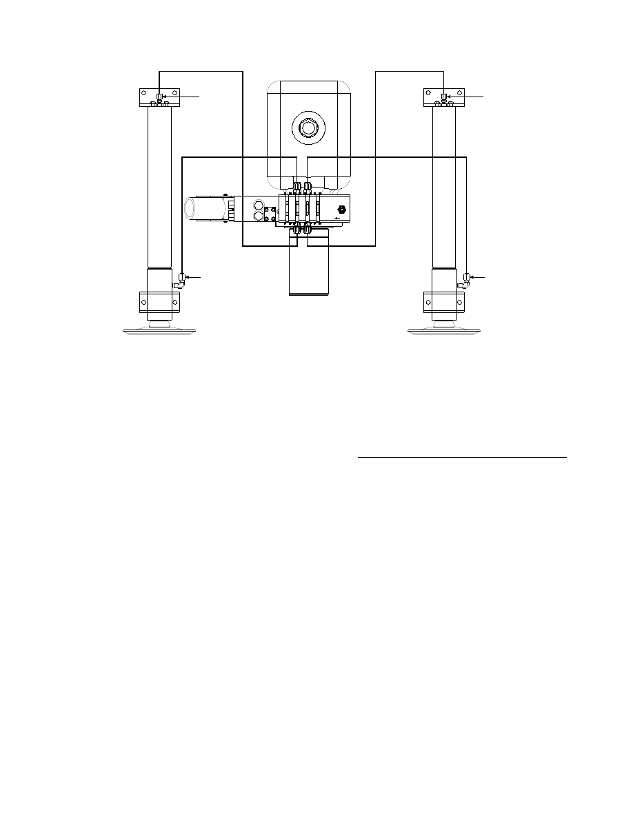
2-2.2 Hydraulic switch system with double-acting jacks.
The basic operation of a hydraulic switch system with double-acting jacks is same as the system with
single-acting jacks (2-2.1) except one thing; the pump must be used to retract the jacks. The double-acting
jacks have no return springs. Physically, the valve is the same; but, we run two hoses to the jacks instead of
one. Hydraulically, we use a regenerative hydraulic circuit to extend the jacks. The simple explanation for
regenerative is; we direct pressure to both sides of the cylinder. This creates a greater force on the cap side
of the cylinder and forces fluid from the rod side of the cylinder as the rod extends. This fluid if forced into
the cap end of the cylinder, thus, a regenerative cylinder. See ML37939 Regenerative Hydraulic Circuit
under “Advanced Hydraulic Theory” in the HWH Online Technical School for a detailed explanation of the
regenerative hydraulic circuit.
Like with the single-acting jacks, the control levers can be “feathered” to speed up or slow down the speed
of the jacks. When hitching the trailer, the weight of the trailer will force the jacks to retract without the
pump on when the control levers are pushed to the retract position. The pump will have to run to retract the
jacks completely after the weight of the trailer is not on the jacks.
3. LANDING GEAR SYSTEMS WITH ELECTRIC SWITCHES.
All electric switch controlled landing gear systems, past and present, use a room extension style manifold
with electric solenoid valves. The original landing gear system used the room manifold with the large
solenoid valves. These early systems were only available with single acting jacks equipped with springs.
The valve manifold only used one solenoid valve, the retract valve, unless there was a room extension
operated with the same manifold. If there were room extensions, the landing gear system used both the
extend and retract valves. There was no independent control of the landing gear jacks. If two jacks were
used, they were just teed together. The newer systems use a room style manifold with the small solenoid
valves and can be used with single or double-acting jacks. The new systems are available with or without
an auxiliary hand pump. The latest version of the new system will probably have a large solenoid valve as
the “retract” valve. If the system has room extensions, you will see large and small valves on the same side
of the manifold, the large valves being for the landing gear. The new style systems are actually simpler
electrically than the older systems. You will see this as we describe the different systems.
UNDERSTAND OPERATOR’S MANUAL BEFORE USING. BLOCK FRAME AND TIRES
SECURELY BEFORE REMOVING TIRES OR CRAWLING UNDER VEHICLE.
PENDANT
CONTROL
CAUTION!
STOP
EMERGENCY
RETRACT
EXTEND
HWH HYDRAULIC LANDING GEAR
H
CORPORATION
STORE
ON
H
W
R
One or Two Single Acting Landing Gear Jacks
Figure 6
3-1 Touch panel controlled landing gear system.
This is the first electric switch controlled landing gear system HWH produced. The system used a room
extension style manifold with large solenoid valves and one or two single acting jacks with return springs.
The touch panel was usually part of a control pendent but could be mounted permanently. The pendent
allowed the operator to stand away from the trailer while lifting or lowering the trailer with the landing
gear.
The touch panel has an “ON” button with an On indicator light, a “STORE” button with a Store indicator
light, an “EMERGENCY STOP” button, an up arrow button (extend landing gear) and a down arrow
button (retract landing gear). Some vehicle manufacturers supply a master power switch for the system to
control when the touch panel could be used. For any touch panel function to operate, the On indicator light
must be lit. When the “STORE” button is pushed, the Store indicator light will be on. The following is the
function of the panel buttons:
1. ON button. This button turns the panel on. The On indicator light will come on when the ON button is
pushed. With the On indicator light lit, all of the panel buttons will function.
2. STORE button. This button is used to store both jacks. This touch panel has an early version and a
later version with a STORE button change. The ON indicator light must be on for the STORE button to
function with either version of the panel. On the early version panel, the store function latches in
whenever the STORE button is pushed. The jacks retract without holding any buttons. The panel will turn
off 2 minutes after the jacks have fully retracted. The later version panel uses jacks that are equipped with
pressure switches. The STORE button will not work until the weight of the trailer is off the landing gear
jacks. Then the STORE button can be pushed and the store function will latch in. The panel will
automatically shut off 2 minutes after the jacks are fully retracted.
3. EMERGENCY OFF button. This button will turn the panel off, halting any operation that is in
progress. The valves and pump will turn off and any extension or retraction of the jacks would stop.
4. Up Arrow button. This is a momentary button used to extend the landing gear jacks. The pump will
run and both jacks will extend while this button is pushed. When the button is released, the pump will shut
off and the jacks will remain in their present position.
5. Down Arrow button. This is a momentary button used to retract the landing gear jacks. Both jacks
will retract while this button is pushed. When the button is released, the jacks will remain in their present
position. This button should be used to hitch the trailer to the tow vehicle with either the early or
later version of the touch panel. Note: This panel can be modified to accommodate double-acting jacks.
When modified, the pump will run when the STORE button or the Down Arrow is used. The panel
modification can only be done at HWH Corporation.
CORPORATION
CORPORATION
USING. BLOCK FRAME AND TIRES SECURELY BEFORE REMOVING TIRES
WARNING!
OR CRAWLING UNDER VEHICLE.
UNDERSTAND OPERATOR’S MANUAL BEFORE
EXTEND
RETRACT
LANDING GEAR
LF
R
RETRACT
EXTEND
RF
RETRACT
RF
EXTEND
LANDING GEAR
AND TIRES SECURELY BEFORE REMOVING TIRES
UNDERSTAND OPERATOR’S MANUAL BEFORE USING. BLOCK FRAME
OR CRAWLING UNDER VEHICLE.
WARNING!
EXTEND
RETRACT
LF
R
W
H
HYDRAULIC SYSTEMS
H
HYDRAULIC SYSTEMS
H
W
H
ON
TIRES OR CRAWLING UNDER VEHICLE.
TIRES SECURELY BEFORE REMOVING
BEFORE USING. BLOCK FRAME AND
UNDERSTAND OPERATOR’S MANUAL
H
WARNING!
H
CORPORATION
LANDING GEAR
W
RETRACT
EXTEND
R
LF
OFF
RF
Figure 7
CONTROL SWITCH
WIRING FOR
SINGLE-ACTING
LANDING GEAR
+12 VOLT
CONTROL
FOR EXTEND
VALVE
+12 VOLT
CONTROL
FOR RETRACT
VALVE
+12 VOLT
CONTROL
FOR PUMP
RELAY
+12 VOLT
TO COMMON
TERMINALS
CONTROL SWITCH
WIRING FOR
DOUBLE-ACTING
LANDING GEAR
+12 VOLT
CONTROL
FOR EXTEND
VALVE
+12 VOLT
CONTROL
FOR RETRACT
VALVE
+12 VOLT
CONTROL
FOR PUMP
RELAY
+12 VOLT
TO COMMON
TERMINALS
Figure 8
The following manuals contain operating information, hydraulic diagrams and electrical diagrams.
ML12621 Operator’s manual for landing gear system with one or two single-acting jacks.
ML17652 Operator’s manual for landing gear system with two single-acting jacks with a room extension.
3-2 Rocker or toggle switch controlled landing gear systems.
These are the most common panels that are presently used. These controls can be used with single-acting
jacks or double-acting jacks. The difference in the controls is the pump does not run when retracting single-
acting jacks. This is accomplished with a simple wiring change at the control switches. The switches used
are momentary ON-OFF-ON double pole-double throw switches.
Note: The common terminals of the control switches are sometimes wired with individual power
supplies; battery power for the pump side and switched power from the pump relay for the valve
control side. The trailers should also have a master power switch for the landing gear/room
extensions. This switch may be supplied by the trailer manufacturer or HWH. This switch will
supply battery power to the HWH control switch panel. Switch wiring depends on the manufacturer
and the type of jacks that are used. Always refer to system electrical schematics for specific wiring
information
The rocker/toggle switch landing gear systems all use a room extension style manifold. These manifolds
can accommodate one or more room extensions along with the landing gear and are available with or
without an auxiliary hand pump. At present, these manifolds are equipped with small solenoid valves that
have a special manual valve release cam that is not used with motorized vehicle systems. The next
generation manifolds will have a large valve for the retract side of the landing gear only. Each landing gear
jack has a pair of valves, an extend valve and a retract valve. Systems with single-acting jacks have one
hose per jack which attaches to the cap side of the jack. Systems with double-acting jacks have two hoses
to each jack, one to the cap side of the jack and one to the rod side of the jack. The double-acting landing
gear systems operate with a regenerative hydraulic circuit. See ML37939 “Regenerative Hydraulic
Circuits” under “Advanced Hydraulic Theory” in the HWH Online Technical School.
LEFT SIDE JACK
3E
2E
RIGHT SIDE JACK
2R
P42088
LEFT
JACK
EXT
RET
3R
P42089
RIGHT
JACK
EXT
RET
TOP VIEW
LEFT SIDE JACK
RIGHT SIDE JACK
System with Single-Acting Jacks
3E
2E
2R
P42088
LEFT
JACK
EXT
RET
3R
P42089
RIGHT
JACK
EXT
RET
TOP VIEW
System with Double-Acting Jacks
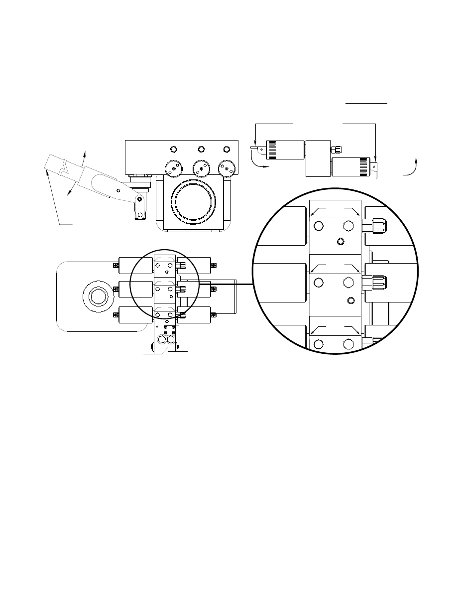
Figure 9
OPEN
RELEASE CAM
END VIEW
CLOSE
VALVE
POSITION
VALVE OPENED
POSITION
VALVE CLOSED
The following are hydraulic connection diagrams for electric switch controlled landing gear systems. The
valves marked “E” are jack extend valves and the valves marked “R” are the jack retract valves.
The basic operation of the systems is simple. With either single-acting or double-acting jacks, when a
rocker or toggle switch is pushed to “EXTEND”, a +12 volt signal from the switch turns the pump relay on.
This supplies voltage to the pump motor. The switch also supplies a +12 volt signal to the extend valve.
This directs fluid to the cap end of the jack to extend the jack. When the control switch is pushed to
“RETRACT”, the switch directs a +12 volt signal to the pump relay and retract valve (double-acting jacks),
or to just the retract valve (single-acting jacks). This allows fluid to return to the pump from the cap end of
the jack so the jack can retract. This is accomplished by springs pulling the foot of the jack up (single-
acting jacks) or the pump directing fluid to the rod side of the jack to force the jack to retract (double-acting
jacks).
The variables in how the system is put together do not affect the operation of the system, only how the
control switches are powered. If there is a master power switch, it must be on to supply power to the
control switch panel. If the HWH control panel has a key switch, this switch must be on to supply power to
the landing gear control switches. Always refer to specific system schematics for wiring information.
4 The auxiliary hand pump. The auxiliary hand pump is a backup pump for systems that incorporate an
electric pump motor. For systems with the hydraulic switches and no electric motor, the hand pump is the
only pump in the system. The hand pump can be used to operate the landing gear or room extensions. The
auxiliary hand pump is a two stage pump. The first stage is high flow and low pressure. The second stage is
a low flow with high pressure. This allows the jacks to be extended and retracted at a quick rate but still be
able to produce enough pressure to lift the trailer as needed. As the jacks meet some resistance such as
MOTION
OPERATING
HANDLE
HAND PUMP
AUXILIARY
TOP VIEW
ROOM
B-STYLE
JACK
RIGHT
LEFT
JACK
EXT
EXT
RET
RET
P42088
RET
P42089
EXT
P42091
FRONT VIEW
FIG 1
LEFT
JACK
EXT
RET
P42088
OPEN
JACK
RIGHT
EXT
RET
P42089
ROOM
B-STYLE
RET
EXT
P42091
RELEASE CAM
END VIEW
CLOSE
(1) room as indicated by the labels shown in FIG 1.
here represent a (3) function system of (2) jacks and
solenoid valves will very for each system. The diagrams shown
Each hydraulic function requires a pair of solenoid
valves one each for the extend and retract procedures. The
number of functions and the items controlled by each pair of
Figure 10
trying to lift the trailer, the pump handle will seem to “snap” as the pump goes to the second stage. The
pumping action will seem easier at first as the second stage creates more pressure.
Nothing special has to be done to use the hand pump. Insert the pump handle into the handle receptacle.
The handle receptacle swivels to accommodate accessibility issues. Use the valve release cams to open the
appropriate valve(s). Move the pump handle in an up and down motion. This produces the flow and
pressure to extend or retract the jacks or rooms. Normally the auxiliary pump will not need to be primed,
but if for some reason that does become necessary, refer to the owner’s manual. Page MP44.0009 is the
instruction sheet for priming the auxiliary hand pump.
Wyszukiwarka
Podobne podstrony:
Landing Page Color Change Instructions
Osprey CAM 104 D day 1944 (2) Utah Beach & The US Airborne Landings
Transponder Landing System, Lotnicze różności
Perfect Landing
The New Money Masters Series Landing Page
Navy Foreign State Aircraft Landing Procedures
Osprey CAM 104 D day 1944 (2) Utah Beach & The US Airborne Landings
Printing Landing Minimums
Landing Pages that Work 2013
Francesco Landini Deh! Dimmi tu (Squarcialupi Codex)(1)
Robert Zubrin First Landing
Stuart, Anne Cameron s Landing (v1 0) [rtf]
Crash Landing on Iduna Arthur Tofte
Landing the Air Marshal – Jennifer Blackwood
Leinster, Murray Second Landing
3 Doors Down Landing In London 1
105114bdfd234939e78 96154448shared dictation landing
#0554 – An Emergency Airplane Landing
więcej podobnych podstron