
VERO UK
1
VERO UK TRAINING MATERIAL
Version 20
Cutting a punch
VERO UK
2
Cutting a Punch
Things that will be covered in this section.
•
Editing geometry start/end points
•
Applying additional tags
•
Moving start points
From the menu select file > Open
Open the file - Punch.wkf
Select Machining > CAM Navigator,
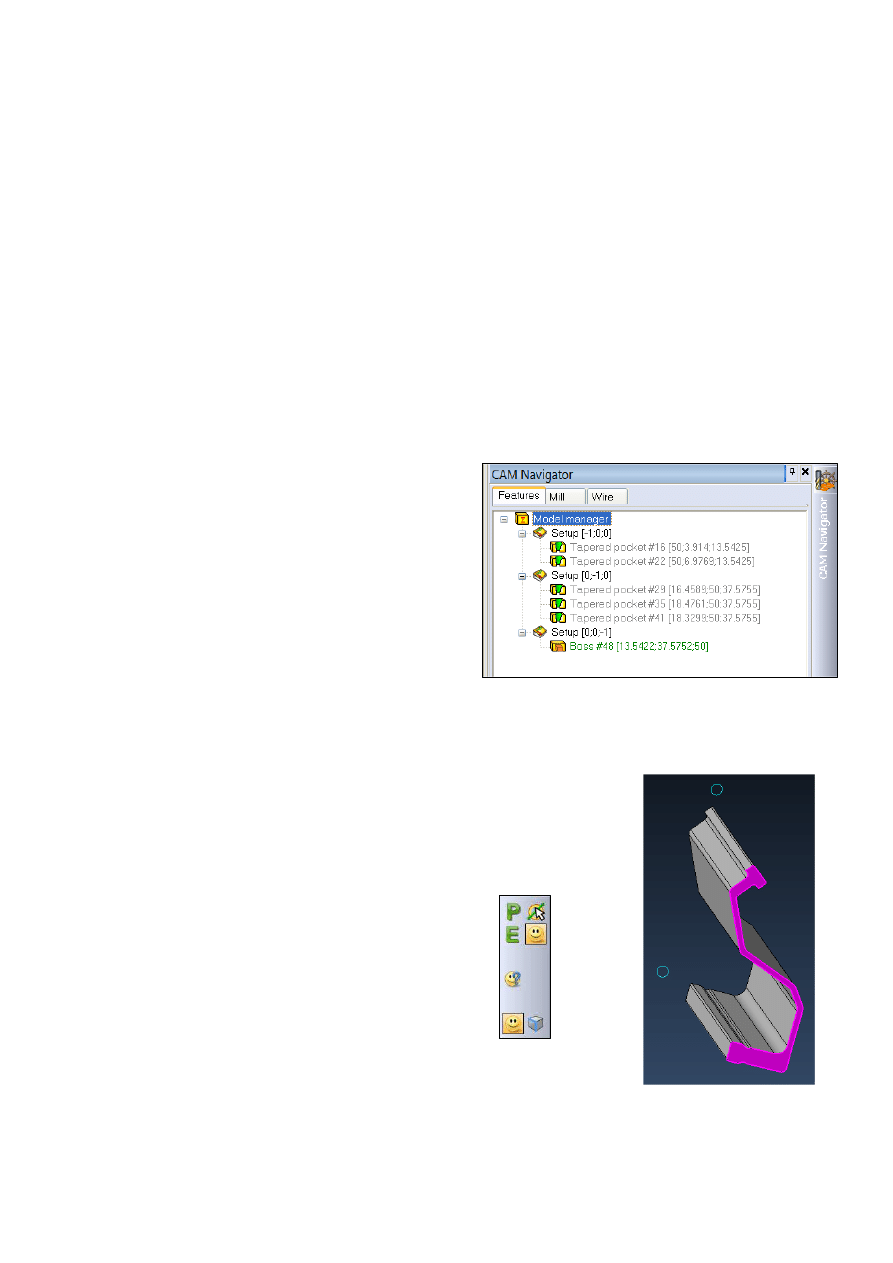
If the recognition on this part is done by
righthand clicking the model manager,
the result would be that a total of 6
features would be created on 3 different
setups, in this case it may be
acceptable but on models with a large
number of features this could make for
a very cluttered model manager window
To ensure that we only find features oriented in the Z direction we will
create a setup to use for the feature recognition,
Righthand click on the Model manager and select, Add
setup, the system will ask you to pick a face or element,
ensure the Face selection icon is active and pick the top
face of the punch as shown
VERO UK
3
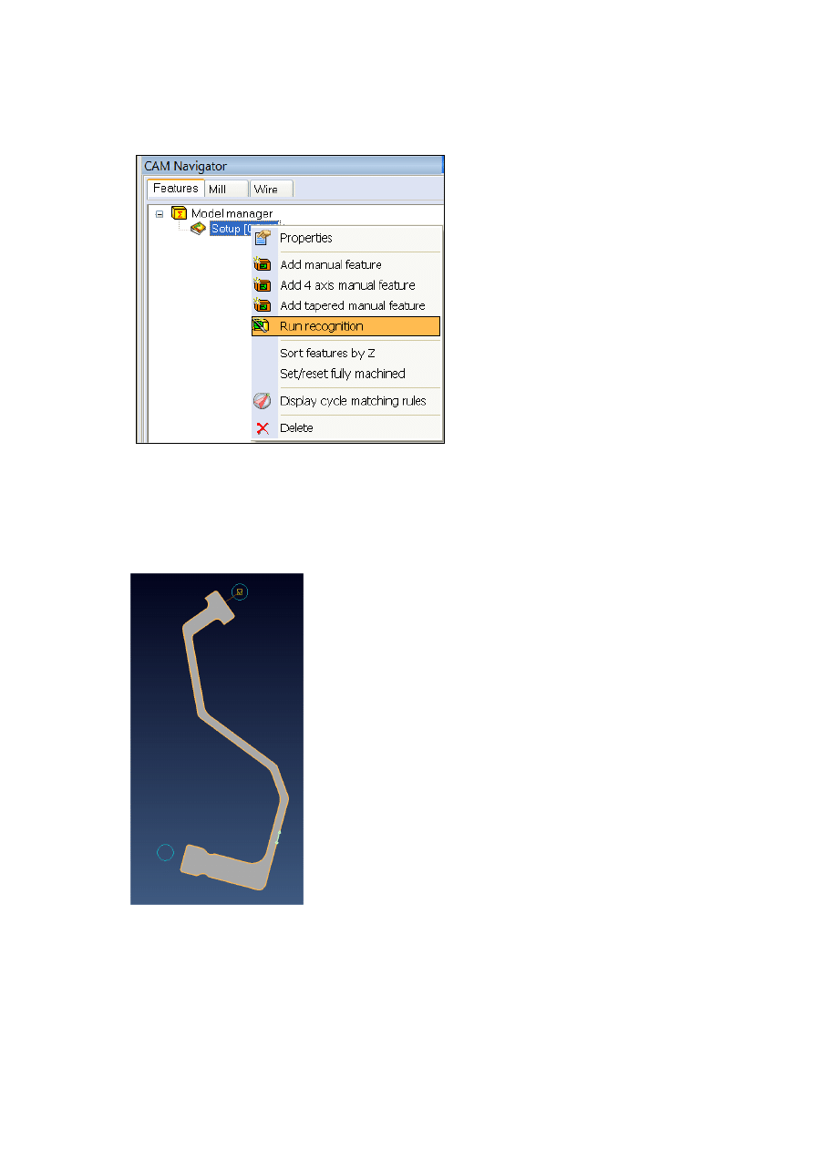
The Cam navigator will now have a new Setup added to it, righthand click
the setup and run recognition to extract the punch feature
The result will be the addition of a single Boss feature to the previously
created setup, add a 2-axis wire EDM opperation to this feature.
The wire start/retract point for this operation has
been automatically generated from one of the
small circles.
VERO UK
4
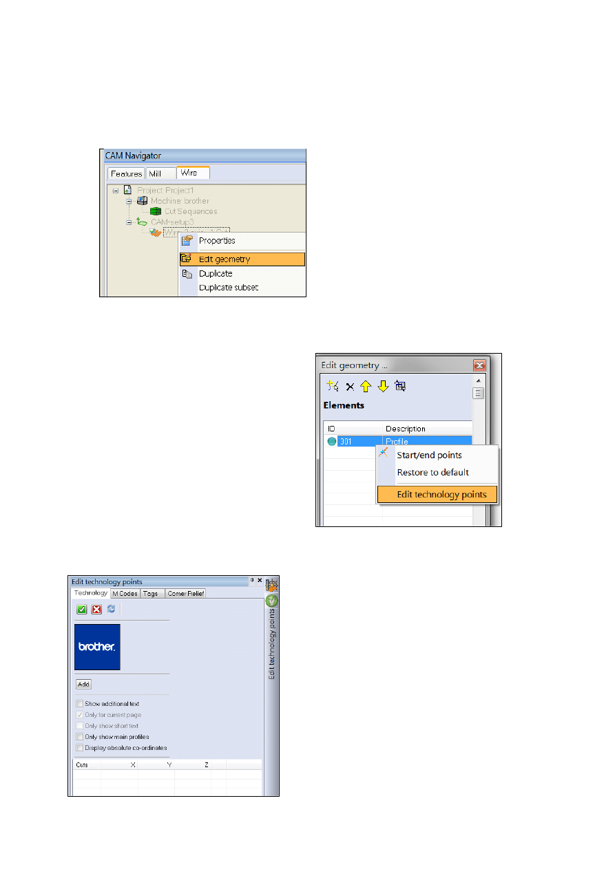
You may have noticed that there are two circles drawn, this is because we
will be using 2 start points for this punch to reduce the chances of the
punch twisting during cutting.
Righthand click on the wire
operation and select Edit
geometry
Righthand click on Edit Tec points
You will now be pesented with a new
panel on the right of the screen, select
the Tags tab, then the Add button
VERO UK
5
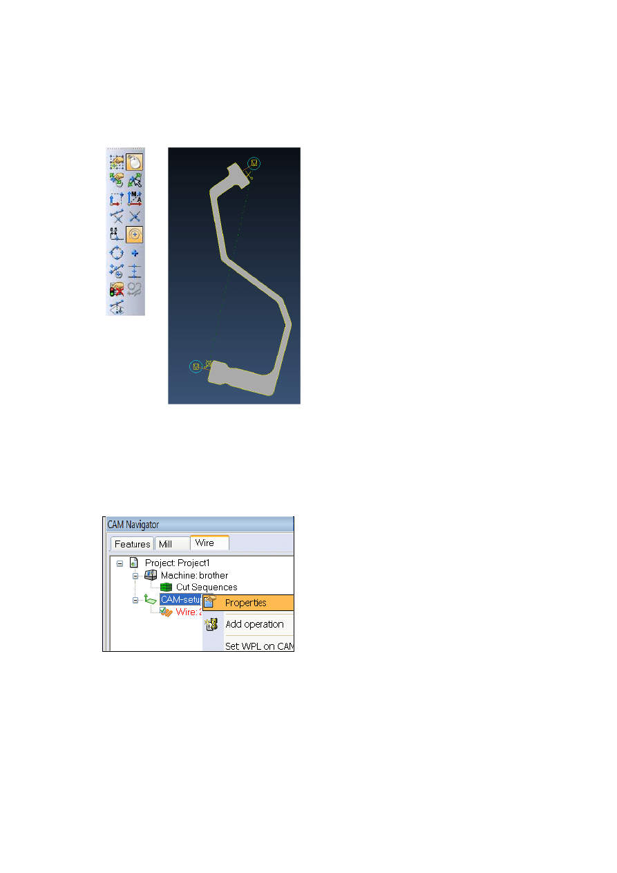
Ensure the centre of a circle/arc selection icon is active and pick the
second circle, the new approach/retract/start/stop will be created in this
position.
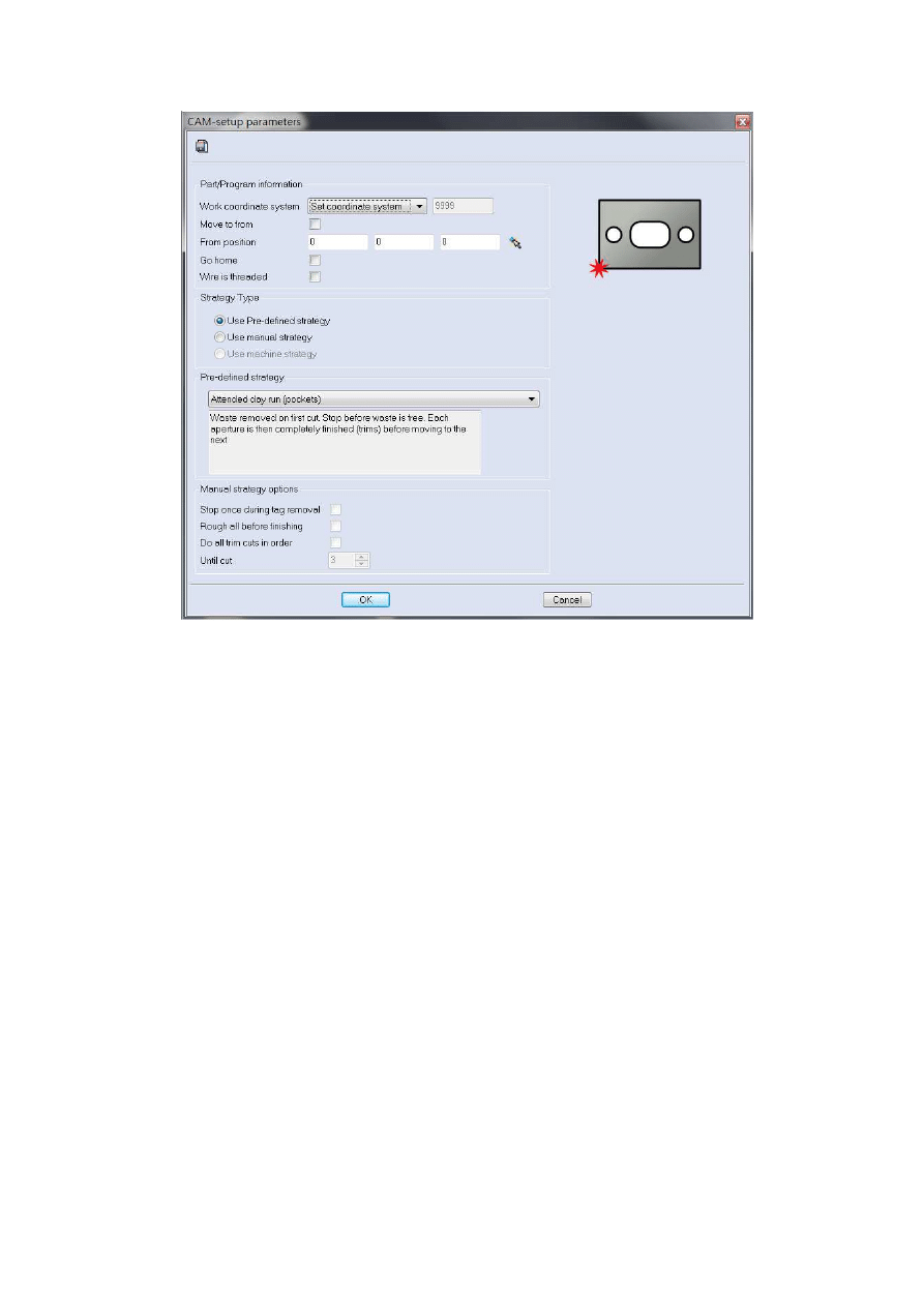
Righthand click on the CAM-setup and select the properties option from
the menu. *
Activate Use Pre-defined strategy and select Unattended bosses from
the drop-down menu, click OK
VERO UK
6
Select the Wire tab in CAM Navigator, righthand click on the Project,
select properties, choose a Piece material and Wire and click OK
*Tip – You can also lefthand double click on most options
VERO UK
7
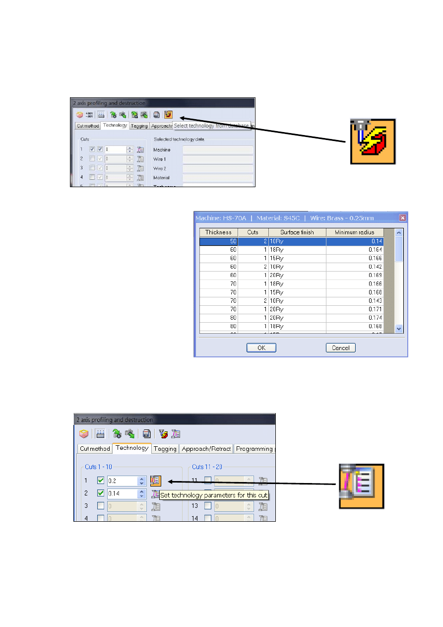
Righthand click on wire and, select properties, click the Select
technology from database button
and select a technology with
a thickness of 50mm and 2
cuts, click OK
Note – This dialog will be
different for each machine
manufacturer
This will load-in the offsets and register settings for your machine, click the
Set technology parameters for this cut button to see the register
settings that have been loaded
VERO UK
8
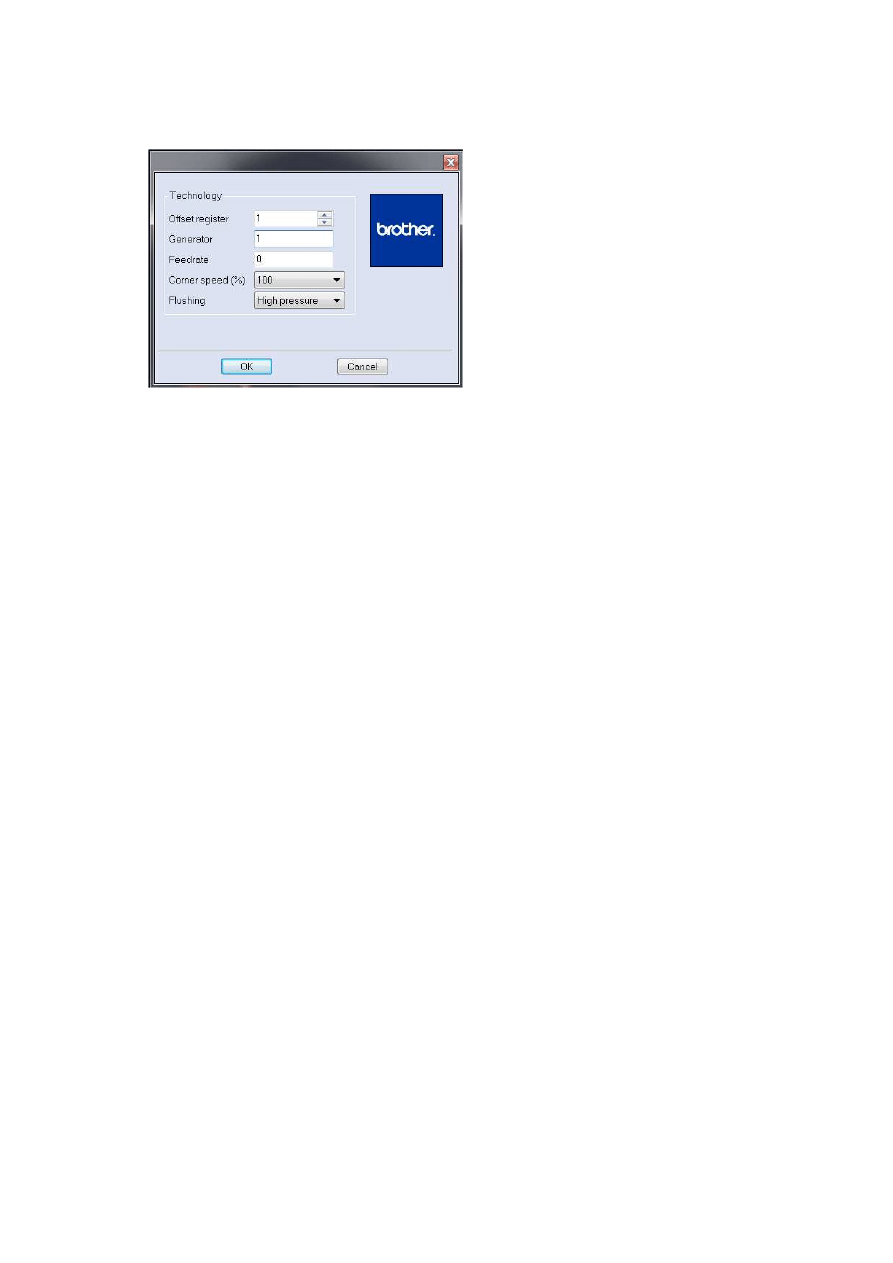
Note - This dialog will look different for each machine manufacturer
Click OK
Use the following parameters for this machining
Use distance for tag with tag distance of 1mm
Stop at end of tag cut = ticked with distance 0.4 *
Lead off distance 0.5mm
Upper nozzle 50mm
Lower nozzle 0mm
Select OK on the dialog
Righthand click Path-Lab from the CAM Navigator and run the wire path
simulation to check your part
* This will add an additional stop at the end of the job just prior to the
punch becoming detached, this will prevent the punch from accidentally
dropping, a light tap with a soft hammer will release the part.
Wyszukiwarka
Podobne podstrony:
6 Wire?M V20 cutting a punch
12 Wire?M V20 Cutting a 4 axis part
4 Wire EDM V20 2axis from linearc
5 Wire EDM V20 2axis from solids
9 Wire?M V20 No Core Cutting
Wire?M V20 front page
10 Wire?M V20 Taper & Land
8 Wire?M V20 cut sequencing
5 Wire?M V20 *xis from solids
4 Wire?M V20 *xis from linearc
7 Wire?M V20 Open Profiles
11 Wire?M V20 4 axis profiles & constraints
83 1183 1198 Influence of Non Metallic Inclusions in Super Finish Wire Cutting
Cutting Board 1
Cutting Edge Placement Tests
EDM trochimiak
więcej podobnych podstron