
Appendix 8.2.8 Firewall Services Module
Overview
This appendix includes the following topics:
■
Objectives
■
FWSM Overview
■
Network Model
■
Getting Started
■
Using PDM with the FWSM
■
Troubleshooting the FWSM
■
Summary
Objectives
Upon completion of this appendix, the student will be able to
perform the following tasks:
■
Describe the FWSM features and benefits.
■
Explain the similarities and differences between the FWSM
and the PIX Security Appliance.
■
Describe a typical deployment scenario for the FWSM.
■
Initialize the FWSM.
■
Configure the switch VLANs.
■
Configure the FWSM interfaces.
■
Prepare the FWSM to work with PDM.
■
Install PDM on the FWSM.
FWSM Overview
FWSM Key Features
FWSM Key Features (Cont.)
FWSM and PIX Security Appliance Comparison
FWSM and PIX Security Appliance Feature Comparison (cont.)
Cayalyst 6500 Switch Requirements
This section introduces the FWSM.
The Cisco Firewall Services Module (FWSM) is an integrated
module for the Cisco Catalyst 6500 Series Switch. The Cisco
Catalyst 6500 provides intelligent services such as firewall
capability, intrusion detection, and virtual private networking,
along with multilayer LAN, WAN, and MAN switching
capabilities.
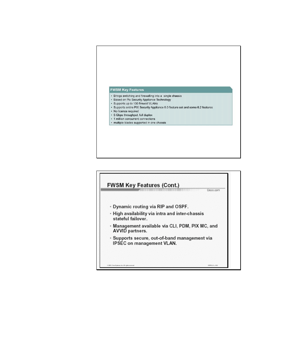
The Cisco FWSM is a high-performance firewall solution,
providing 5 Gbps of throughput per module and scaling to 20Gb of
bandwidth with multiple modules in one chassis. The FWSM is
completely VLAN aware, offers dynamic routing, and is fully
integrated within the Cisco Catalyst 6500 Series switches. The
FWSM is based on Cisco PIX Security Appliance technology, and
therefore offers the same security and reliability. It includes the
entire PIX Security Appliance 6.0 software feature set and some of
the features of PIX Security Appliance software version 6.2.
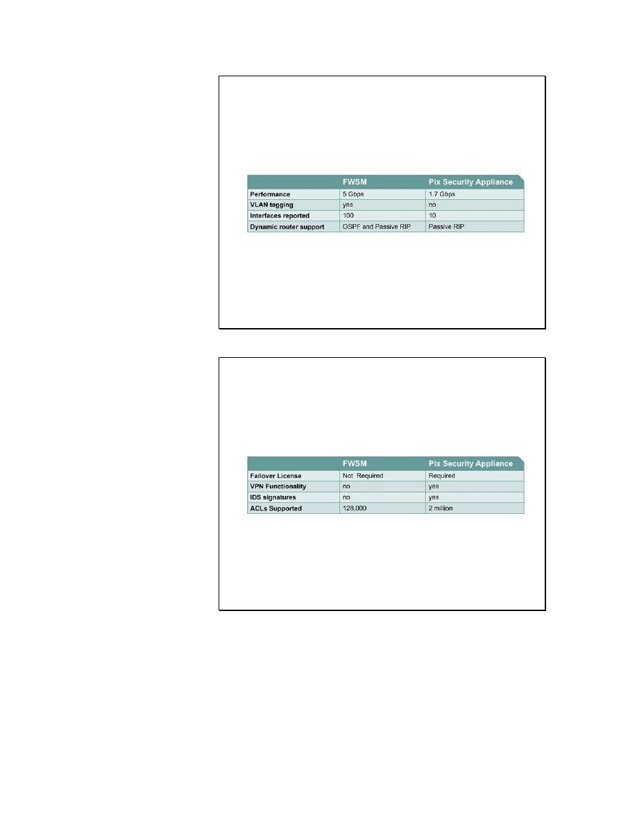
the FWSM also offers dynamic routing via RIP and OSPF, intra-
and inter-chassis failover, a variety of management options, and
secure out-of-band management via IPSec. It supports the
following features of PIX Security Appliance software version 6.2:
■
Command authorization
■
Object grouping
■
ILS/NetMeeting fixup
■
URL filtering enhancement

The FWSM can operate with 802.1q and Inter-Switch Link (ISL)
protocols and supports up to 100 firewall VLANs. Other ways in
which the FWSM differs from the PIX Security Appliance are as
follow:
■
By default, both inbound and outbound connections are
denied.
■
The conduit command is not supported.
■
Active X and Java filtering fixups are not supported.
■
By default, the http fixup is disabled.
■
Bi-directional NAT is not supported.
■
The OSPF routing protocol is supported.
Other differences between the FWSM and the PIX Security
Appliance include the following:
■
No licensing is required.
■
VPN functionality (IPSEC, PPTP and L2TP) for packets
flowing across the firewall is not supported.
■
IDS Syslog messages are not generated.
■
The maximum number of ACLs supported is 128,000.
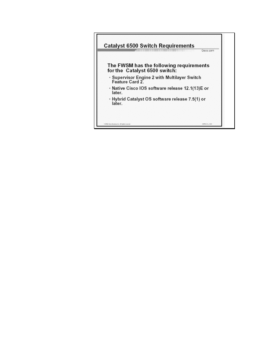
The FWSM occupies one slot in a Cisco Catalyst 6500 switch. Up
to four modules can be installed in the same switch chassis. The
FWSM has the following requirements for the Catalyst 6500
switch:
■
Supervisor 2 with Multilayer Switch Feature Card 2
(MSFC2)
■
Native Cisco IOS® software release 12.1(13)E or higher
■
Hybrid CatOS minimum software release 7.5(1)
Network Model: Typical FWSM deployments and traffic flow
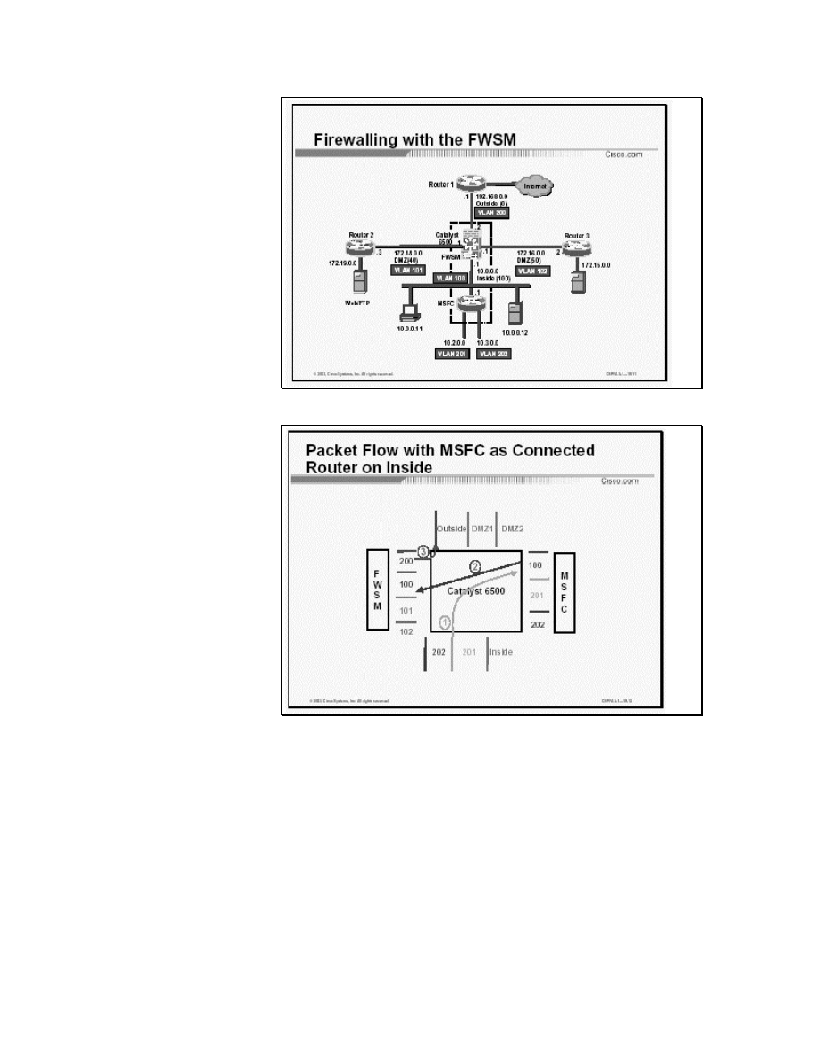
Figure [1]: Firewalling with the FWSM
Figure 2 Packet Flow with MSFC as Connected Router on the Outside
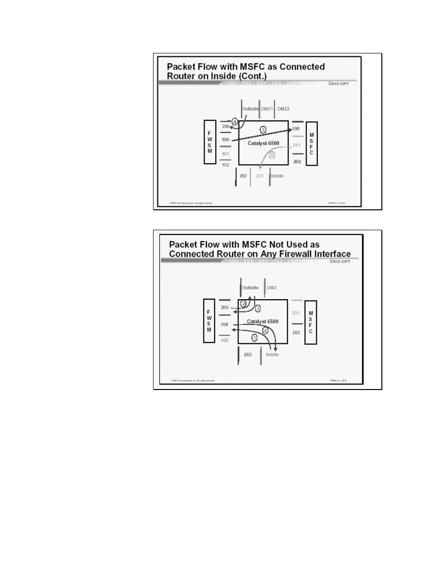
Figure 3 Packet Flow with MSFC as Connected Router on Inside (Cont.)
Packet Flow with MSFC Not Used as Connected Router on Any Firewall
Interface
The Firewall Services Module can be used in a variety of
topologies depending on the network needs. For example, in a data
center the requirement may be to provide access control or
segregate security domains. A security domain can be a collection
of servers with the same security level. Within that domain,
multiple subnets or server farms can exist. When configured to
function on the perimeter of the network, the FWSM module can
provide access control to the inside network as a whole, or
segregate multiple security zones through VLAN interfaces of

different security levels. The security zones can be either in the
same network or can define the boundaries of multiple networks.
The FWSM configuration has the following characteristics:
■
Each firewall interface is a Layer 3 interface. It is uniquely
associated with a VLAN, a Security Level and an IP
address.
■
An interface is firewalled depending on where the interface
is used. The module interfaces are firewalled while all other
interfaces in the system are considered to be outside the
firewall. Each firewall interface has a fixed VLAN.
■
The MSFC may be configured as a connected router on any
one and only one firewall interface, but it is not necessary
to configure the MSFC as a connected router. The FWSM
views all networks or sub-networks beyond an interface as
belonging to the same security level.
■
Traffic from all of the non-firewall VLANs in the switch
(those not recognized by the module) is routed through the
MSFC without being stopped by the firewall.
The Figure [1] shows a firewall configuration with the FWSM[1].
The switch and the router beneath it represent a FWSM and a
Multilayer Switch Feature Card (MSFC) respectively within same
switch. The MSFC, which provides multiprotocol routing with
multi-layer switching for the Catalyst 6000 family switch Ethernet
interfaces, is used in this example as a router on the network inside
the firewall. VLANs 100, 101 and 102 are configured as firewall
VLANs. The MSFC is connected to only one of the controlled
firewall interfaces. All router interfaces configured on the MSFC
are considered to be the same security level as the firewall
interface to which the MSFC is connected. In this example,
VLANs 201 and 202, which are not configured as controlled, are
considered inside the firewall, but traffic between them is routed
by the MSFC without being protected by the firewall.
Figure 2 shows some of the VLANs carrying traffic assigned to the
FWSM[2]. Only the traffic on those VLANs is protected by
firewalls. The arrows trace a connection originating from VLAN
201 (effectively inside) and destined for the outside interface. The
following sequence of events occurs:
1. The packet from the inside interface (VLAN 201) is bridged
to the MSFC interface.
2. The MSFC routes the packet to the firewall interface
(VLAN 100).

3. The firewall module rewrites the packet with the destination
VLAN as 200. The packet from the firewall module is
bridged to the outside interface.
4. The return packet from the outside interface on VLAN 200
is bridged to the firewall interface.
5. The firewall re-writes the packet with the destination VLAN
as 100. The packet from the FWSM is bridged to the MSFC
interface.
6. The MSFC routes the packet back to the inside interface (VLAN
201).
Figure 3 explains the case in which the MSFC is not used as a
connected router on any firewall interface[3]. The arrows trace a
connection originating from VLAN 100 (inside) and destined for
the outside interface. The following sequence of events occurs
1. The packet from the inside interface on VLAN 100 is
bridged to the FWSM interface.
2. Depending on the firewall configuration, the FWSM
rewrites the packet with the destination VLAN as 200. The
packet from the firewall module is bridged to the outside
interface.
3. The return packet from the outside interface on VLAN 200
is bridged to the FWSM interface.
4. Depending on the firewall configuration and earlier state
maintained as a result of packet 1, the FWSM rewrites the
packet with the destination VLAN as 100.
The packet from the firewall module is bridged to the inside
interface.
FWSM Configuration
Figure 1 Getting Started with the FWSM
Figure 2 Initializing the FWSM
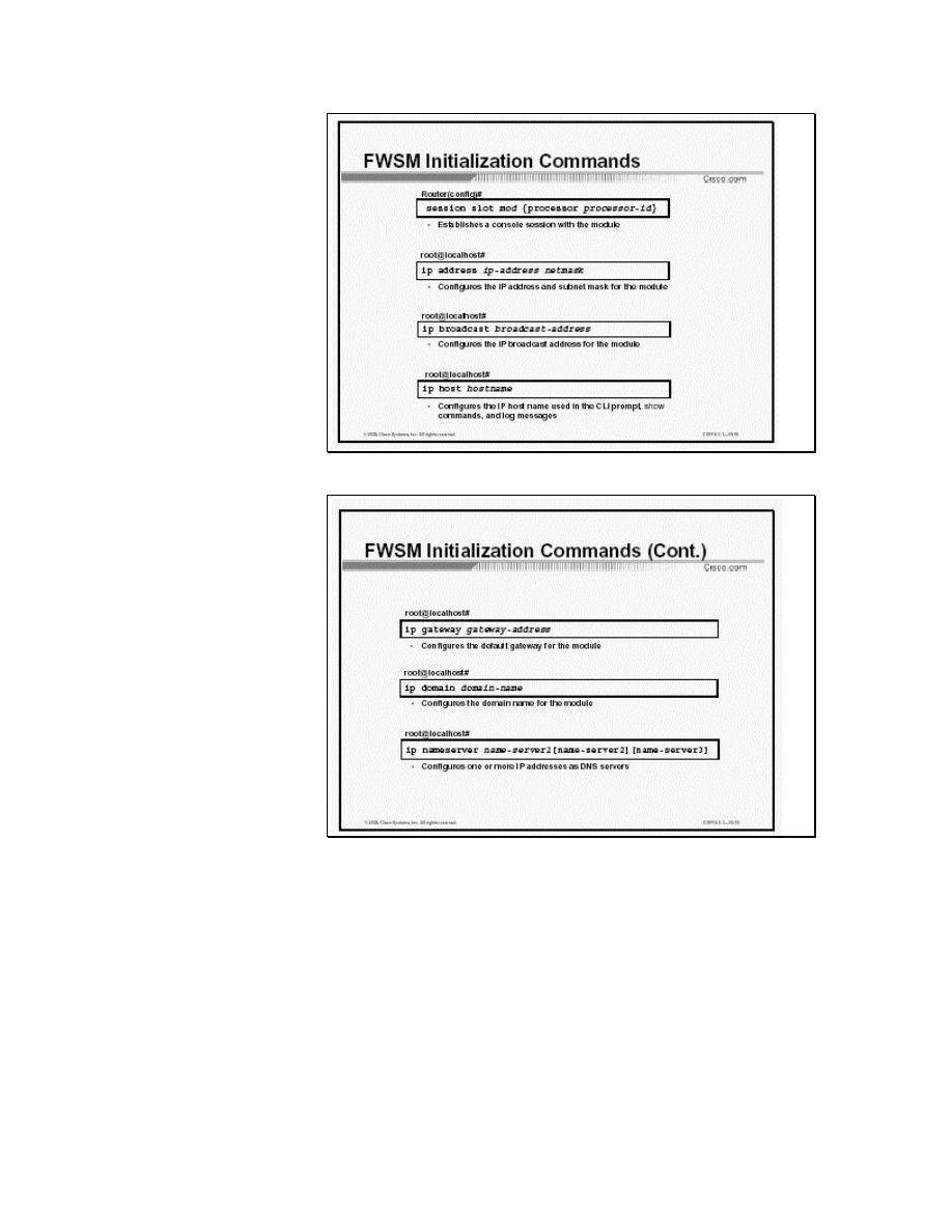
Figure 3 FWSM Initialization Commands
Figure 4 FWSM Initialization Commands (Cont.)
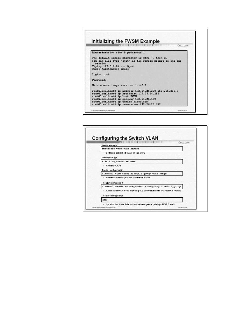
Figure 5 Initializing the FWSM Example
Figure 6 Configuring the Switch VLAN
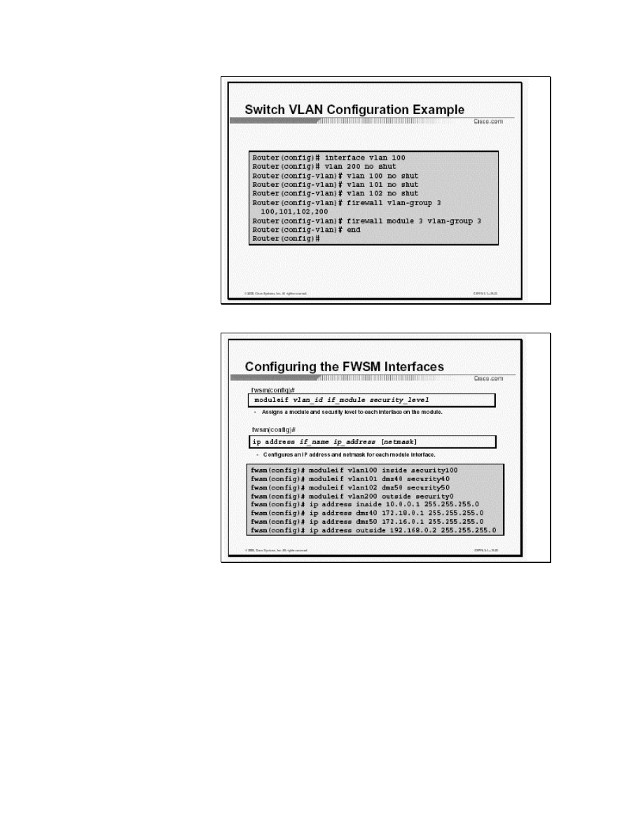
Figure 7 Switch VLAN Configuration Example
Figure 8 Configuring the FWSM Interfaces
Administrators can access the switch Command Line Interface
(CLI) through a Telnet connection to the switch or through the
switch console interface. From the switch console, an administrator
can session into the FWSM to configure it.
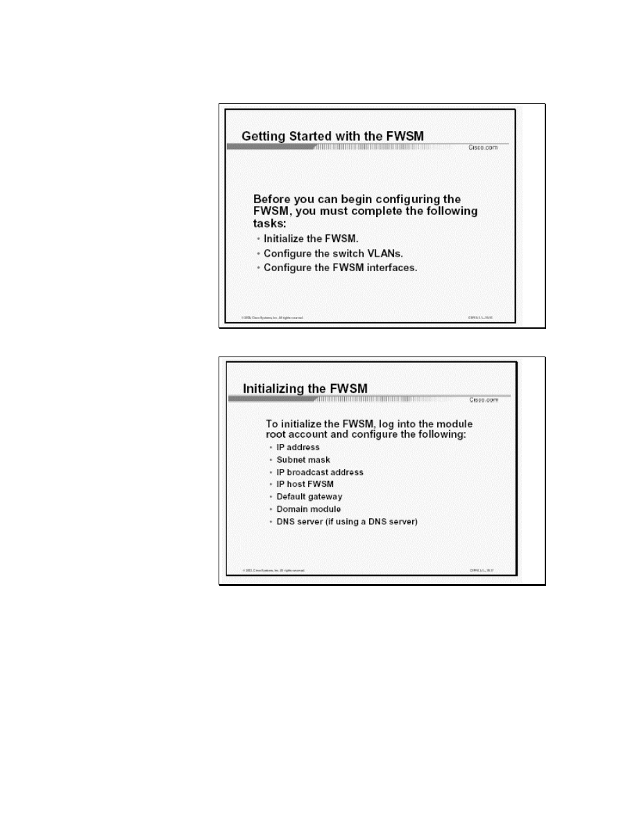
Before an administrator can configure the FWSM, the
following tasks must be completed.
■
Initialize the FWSM
■
Configure the switch VLANs
■
Configure the FWSM interfaces
Step 1
Enter the show module command to verify that the system
acknowledges the new module and has brought it online. The
syntax for the show module command is as follows:
show module [mod-num | all]
mod-num
Number of the module and the port on the module.
all
Displays the information for all modules.
The following is an example of the output of the show module
command:
Figure: The output of the show module command
Step 2
Use the session slot command to establish a console session
with the module. The syntax for the session slot command is
as follows:
session slot mod {processor processor-id}
mod
Slot number
processor processor-
id
Processor ID
Step 3
At the login prompt, type root to log in to the root account.
Step 4
At the password prompt, type root as the root password.
Step 5
Use the ip address command to configure the IP address and
subnet mask. The syntax for the ip address command is as follows:
ip address ip-address netmask
Ip-address
IP address of the module
netmask
Netmask for ip-address
Step 6
Use the ip broadcast command to configure the IP broadcast
address. The syntax for the ip broadcast command is as
follows:
ip broadcast broadcast-address
broadcast-address Broadcast address for network ip-address
Step 7
Use the ip host command to configure the IP host module used
in the CLI prompt, show commands, and log messages. The syntax
for the ip host command is as follows:
ip host hostname
hostname
Module name to be used in CLI prompt,
show commands, and log message
Step 8
Use the ip gateway command to configure the default gateway.
The syntax for the ip gateway command is as follows:
ip gateway gateway-address
gateway-address
Gateway of last resort to be bused by the
module
Step 9
Use the ip domain command to configure the domain name for
the module. The syntax for the ip domain command is as
follows:
ip domain domain-name
domain-name
Domain name for the module
Step 10
Use the ip nameserver command to configure one or more IP
addresses as DNS name servers. The syntax for the ip
nameserver command is as follows:
ip nameserver name-server1 [name-server2][name-server3]]

name-server1
IP address of DNS sever(s)
name-server2
IP address of second DNS server if using a
second DNS server
name-server3
IP address of third DNS server if using a third
DNS server
Figure 5shows an example of initializing a firewall module in Slot
9 of a Catalyst 6500 switch[5].
To prevent losing the switch configuration or having the definition
of a firewall interface becoming out of synchronization between
the module and the route processor, the administrator should first
configure a VLAN on the route processor MSFC and then
configure the VLANs for the module. VLAN IDs must be the same
for the switch and the module. The route processor configuration
for the module requires only a single VLAN for the firewall and a
non-firewall VLAN. After the route processor VLAN is
configured, the controlled VLAN is sent to the module. The
administrator can then configure the module firewall functions.
To enable a single controlled VLAN as the router interface on the
route processor, complete the following steps:
Step 1
Use the interface vlan command to define a controlled
VLAN on the MSFC (route processor). The syntax of the
interface vlan command is as follows:
interface vlan vlan_number
vlan_number
Number of the VLAN
Step 2
Use the vlan command to create VLANs. The syntax for the
vlan command is as follows:
vlan vlan_number no shut
vlan_number
Number of the VLAN
Step 3
Use the firewall vlan-group command to create a firewall
group of controlled VLANs. The syntax for the firewall
vlan-group command is as follows:
firewall vlan-group firewall_group vlan_range
firewall_group
Name of the firewall vlan group

vlan_range
Numerical range of VLAN numbers to be included
in the group
Step 4
Use the firewall module command to attach the VLAN and
firewall group to the slot where the module is located. The syntax
for the firewall module command is as follows:
firewall module module_number vlan-group firewall_group
module_number
Number of the module
firewall_group
Name of the firewall vlan group
Step 5
Use the end command to update the VLAN database and return to
privileged EXEC mode. The syntax for the end command is as
follows:
end
The figure shows how to enable a controlled VLAN in global
configuration mode.
VLAN 100 is defined as the single controlled VLAN on the
MSFC. VLANs 200, 100, 101, and 102 are then created in the
switch and assigned to firewall vlan group 3. Group 3 is attached
to slot 3, the slot in which the FWSM is installed.
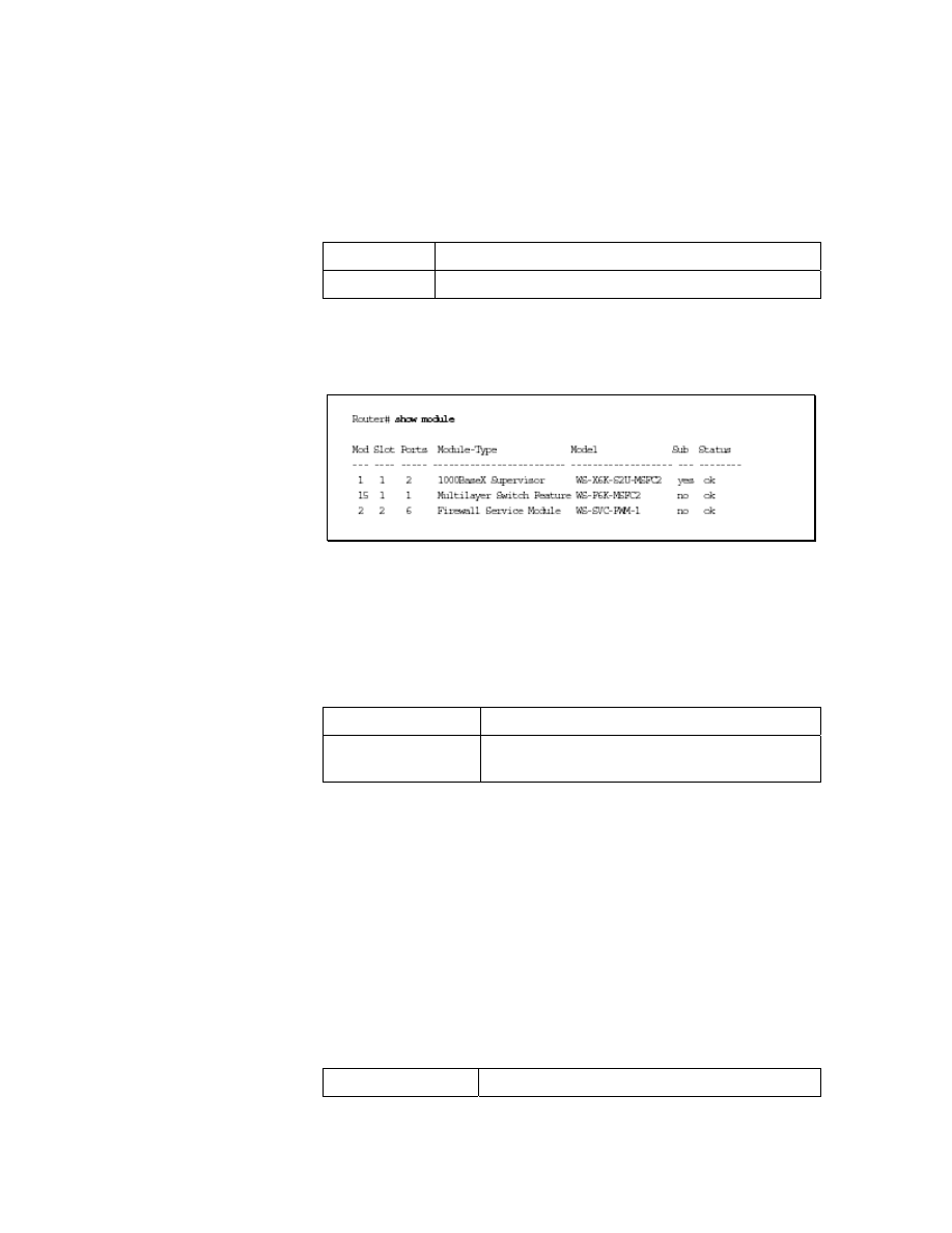
To configure the module interfaces, complete the following steps:
Step 1
Use the moduleif command to assign a module and security
level to each interface on the module. The syntax of the
moduleif command is as follows:
moduleif vlan_id if_module security_level
Step 2
Use the ip address command to configure an IP address and
netmask for each module interface. The syntax for the ip
address command is as follows:
ip address if_module ip_address [netmask]
Once the FWSM is initialized, and the switch vlans and the FWSM
interfaces are configured, the administrator is ready to configure
the FWSM to allow the desired traffic to protected networks. This
will require the creation of Access Control Lists ACLs to allow
outbound as well as inbound traffic. This is because the FWSM,

unlike the PIX Security Appliance, denies all inbound and
outbound connections that are not explicitly permitted by ACLs.
Configuring the firewall policy in the FWSM is much like doing so
in the PIX Security Appliance because the FWSM application
software is similar to that of the PIX Security Appliance software.
For a description of the PIX Security Appliance commands
supported by the FWSM, go to the following
This page contains the following:
■
Commands that support the maintenance software
■
Cisco IOS commands that support the FWSM
■
New commands specific to the FWSM
■
PIX Security Appliance commands that were changed for
the FWSM
■
PIX Security Appliance commands that are not used by the
FWSM
■
PIX Security Appliance commands used by the FWSM and
their corresponding PIX Security Appliance software
versions
Using PDM with the FWSM
Figure 1 PDM and the FWSM
Figure 2 Preparing the FWSM for PDM
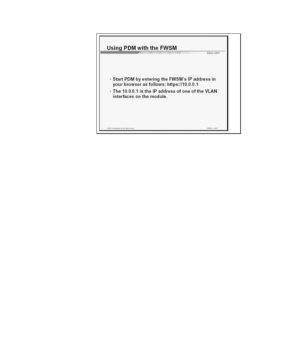
Figure 3 Using PDM with the FWSM
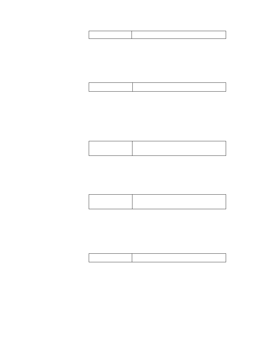
The PDM can be used to configure and monitor the FWSM. When
running on the FWSM, PDM looks somewhat different because it
does not have the Wizards menu or the VPN tab. Furthermore, the
System Properties Interfaces table looks different. Running on the
FWSM, the interfaces in the table are a combination of interfaces
configured on the FWSM and the output from the show vlan
command. PDM supports VLANs and Syslog rate limiting but
does not support OSPF.
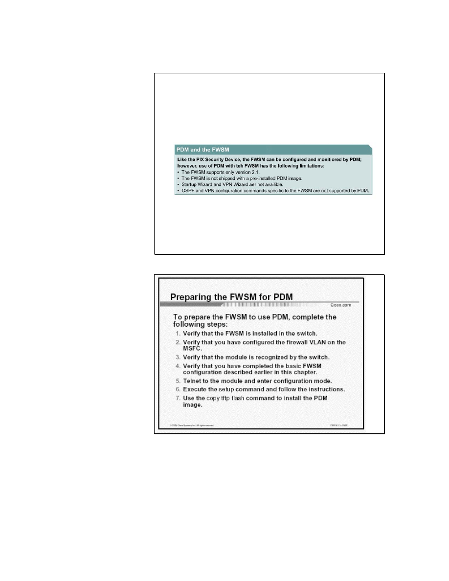
The figure shows the steps needed to prepare the FWSM to use
PDM. Be sure to have initialized the FWSM before attempting to
install PDM.
To start using PDM to configure the FWSM, use the HTTP secure
(https) command and type the following address:
https://IP address of FWSM
The IP address is the address of one of the VLAN interfaces on the
FWSM.
Troubleshooting the FWSM
Figure 4 Status LED
Figure 5 Status LED Descriptions
Figure 6 Resetting and Rebooting the FWSM
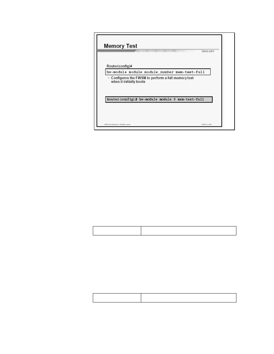
Figure 7 Memory Test
This section provides troubleshooting information that can be used
to determine the possible causes for the Catalyst 6000 FWSM not
functioning properly.
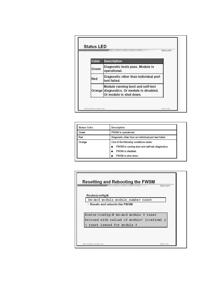
The status LED is a quick method to determine the state of the
FWSM. The status LED is located in the left corner of the module.
LED status colors are described in the following table:
If it is impossible to reach the module through the CLI or an
external Telnet session, enter the hw-mod module
module_number reset command to reset and reboot the
module. The reset process requires several minutes. The syntax for
the command is as follows:
hw-module module module_number reset
module_number
Number of module *** wish to reset
The figure shows how to reset the module, installed in Slot 9, from
the CLI. [***Figure reference—Which Figure shows this?]
When the FWSM initially boots, by default it runs a partial
memory test. To perform a full memory test, use the hw-module
module module_number memtest- full command. The
syntax of the command is as follows:
hw-module module module_number mem-test-full
module_number
Number of module
A full memory test takes more time to complete than a partial
memory test depending on the memory size. The table lists the
memory and approximate boot time for a long memory test.
Memory Size
Boot Time
512MB 3
minutes
1GB 6
minutes
Summary
Figure 8 FWSM Configuration Summary
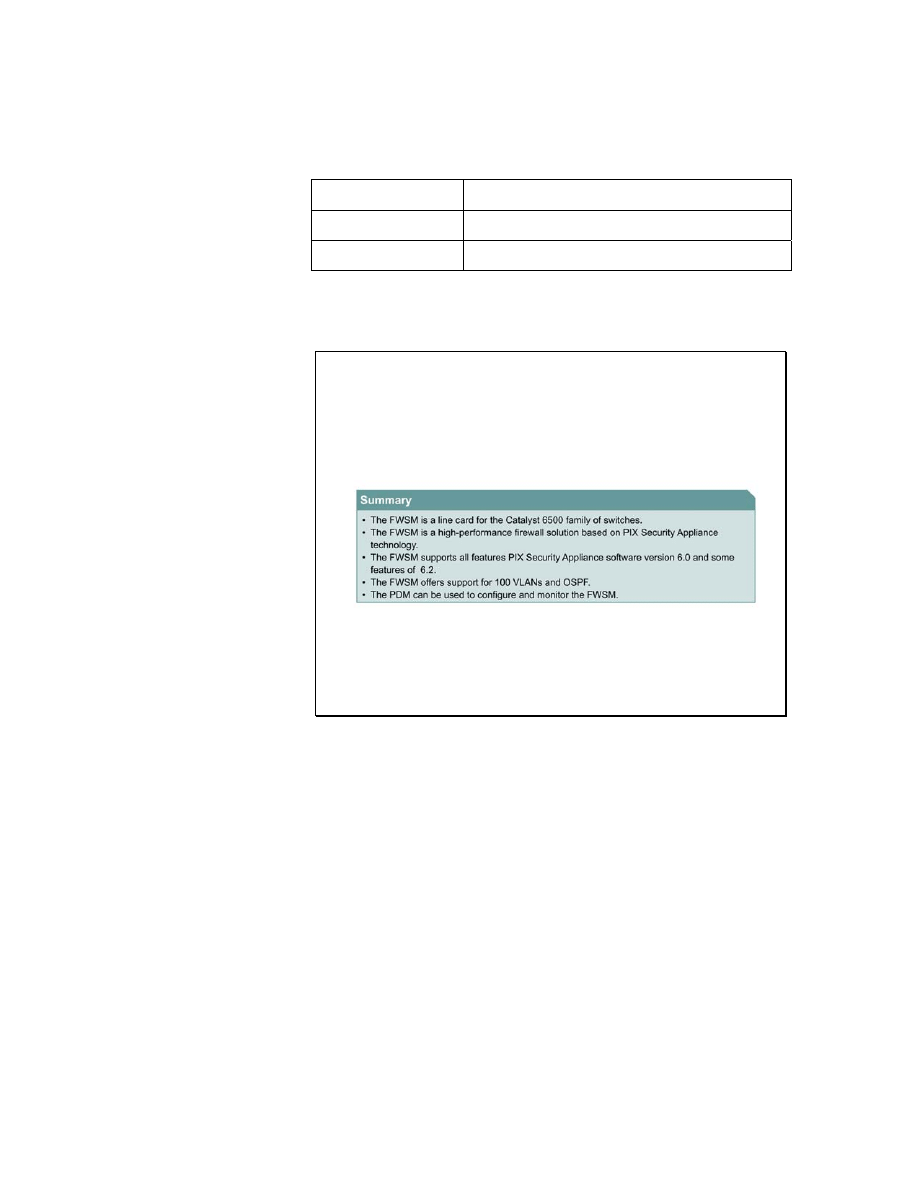
This section has introduced the FWSM line card, summarized its
configuration, and introduced its control via the PDM.
Document Outline
Wyszukiwarka
Podobne podstrony:
W 4 S 52(APP 2)KOLORY I SYMBOLE
APP Najwiekszy Wspolny Dzielnik
App 2DWDM 2OADM
App 11 3 2a
Google App Engine Kod w chmurze googap
app 4 pronun id 67204 Nieznany (2)
App 4 3 1
minimum funkcji unimodalnej APP Minimum Funkcji Unimodalnej
APP Zadania 06 Podprogramy
APP Zadania 07 Tablice Jednowymiarowe
APP Zadania 06 Podprogramy
APP Zadania 09 Rekordy
APP 09 Rekordy
APP 07 Tablice Jednowymiarowe
w 4 s 52(app 2)kolory i symbole
APP 12 Typy Wskaznikowe Ogolne
APP Stosy Kolejki Listy 2011
App 11 3 3
więcej podobnych podstron