2002 CAMRY (EWD461U)
174
ABS (TMC Made)
40A
ABS
NO. 3
From Power Source System (See Page 62)
1E
40A
ABS
NO. 2
1G
5
3B
3B
85
95
3B
3B
64
74
(*1)
(*2)
3B
3B
75
85
3B
3B
74
84
(*1)
(*2)
A
10
A
35
B
9
B
3
A
40
IF3
12
IF3
13
IF4
10
IF4
22
ID1
1
2
1
ID1
4
IF4
8
2
1
IF4
9
IN2
3
IN2
9
SB
SB
W
W–
L
R–
B
W–
L
W
L–
O
L–
W
R–
Y
R–
B
L–
O
L–
W
R–
Y
W
W
R
G
P
L
R
G
P
L
P
L
1
23
13
26
5
32
11
12
33
34
Combination Meter
C 7(A), C 8(B)
S 1
ABS Speed Sensor
Rear LH
A32
ABS Speed Sensor
Rear RH
A33
1
2
(*3
)
1
2
7
10A
IG2
1C
7
B–
O
S
peedom
et
er
N
P
ABS
Brake
2G
8
2O
5
27 A
A
22
A
2
II
W–
B
2R
8
2M
8
3A
3A
64
54
(*1)
(*2)
3A
3A
94
84
SB
SB
(*2)
(*1)
W
W
(* 1)
(* 2)
(* 1)
(* 2)
(*3
)(
*3
)
RL+
RL–
RR+
RR–
+BS
+BM
WA
EBDW
SP1
PN
Skid Control ECU with Actuator
Skid Control ECU with Actuator
2002 CAMRY (EWD461U)
175
10A
ECU–IG
2G
21
1
2
1
2
2G
11
2S
7
2G
23
1
EB
EA
15A
STOP
2G
13
From Power Source System (See Page 62)
3B
3B
52
62
3B
3B
51
61
(* 1)
(* 2)
3B
3B
62
72
3B
3B
61
71
(* 1)
(* 2)
IF4
21
2L
4
2P
4
2G
7
2G
19
Y–
R
Y–
R
W
G–
W
G–
W
W
P–
B
W
W
W
P–
B
B
W
Y
BR
R–
W
W–
B
W–
B
R–
W
R–
W
R–
W
W–
B
W–
B
25
10
14
16
7
13
30
31
8
9
18
2
24
Data Link Connector 3
D 3
S 1
ABS Speed Sensor
Front RH
A 7
ABS Speed Sensor
Front LH
A 6
P
a
rk
ing B
rak
e S
W
P 3
Stop Light
SW
S14
W
2L
3
2G
18
SIL
TC
J
u
n
c
tion C
o
n
nec
to
r
J 7
(P
edal
T
y
pe
)
(Le
v
e
r T
y
p
e
)
* 1 : Automatic A/C
* 2 : Manual A/C
1
2
3A
3A
120
110
3B
3B
109
119
(*1)
(*2)
3A
3A
100
90
3B
3B
99
109
(*1)
(*2)
W
W
W
W
IL2
19
IL2
18
P
N
10A
GAUGE2
2B
6
R–
L
IL1
3
A
/T
I
ndi
c
a
to
r
Li
ght
S
W
A 4
G–
W
R
R–L
1
5
3
LG
–B
IF3
7
LG
–B
TS
15
14
E 3
E 3
W–B
A
A
(Lev
er
T
y
p
e
)
* 3 : 1MZ–FE
FR–
FR+
FL–
FL+
PKB
GND
GND
IG+
STP
VS
D/G
TC
Skid Control ECU with Actuator
Skid Control ECU with Actuator
2002 CAMRY (EWD461U)
176
ABS (TMC Made)
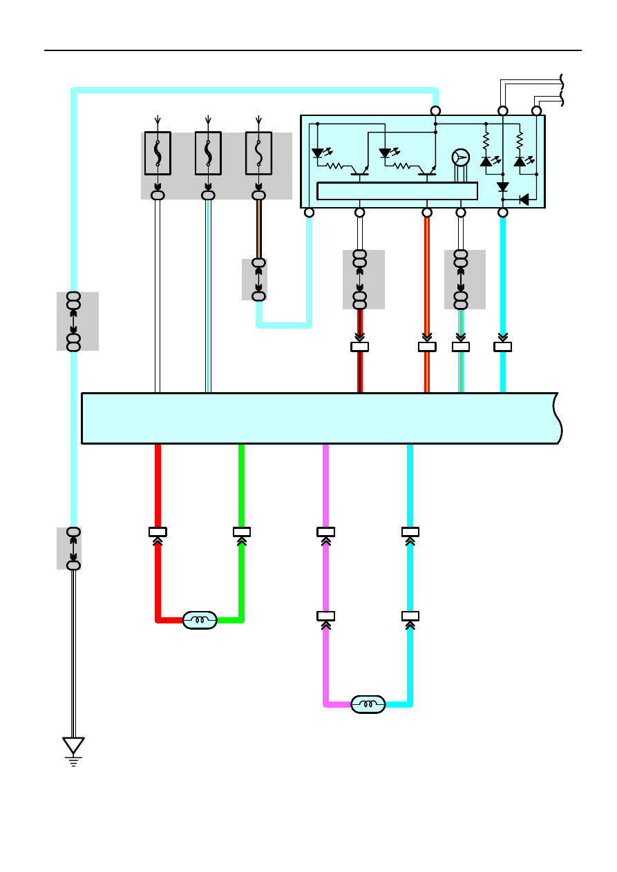
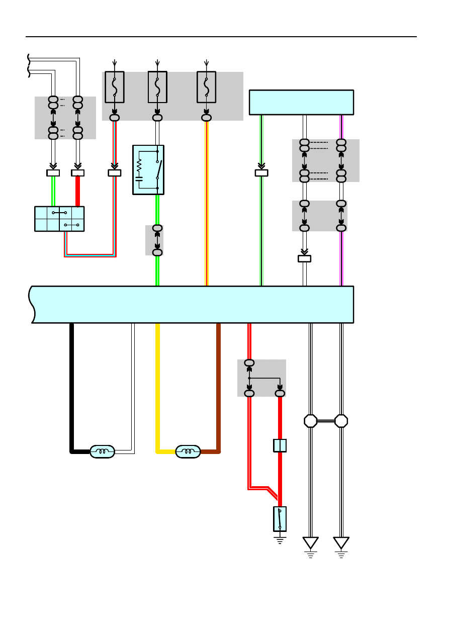
This system controls the respective brake fluid pressures acting on the disc brake cylinders of the right front wheel, left front
wheel and rear wheels when the brakes are applied in a panic stop so that the wheels do not lock. This results in improved
directional stability and steerability during panic braking.
1. Input Signals
(1) Speed sensor signal
The speed of the wheels is detected and input to TERMINALS 9, 11, 31 and 33 of the skid control ECU with actuator.
(2) Stop light SW signal
A signal is input to TERMINAL 10 of the skid control ECU with actuator when the brake pedal is depressed.
2. System Operation
During sudden braking the skid control ECU with actuator has signals input from each sensor, which controls the current to
the solenoid inside the actuator and lets the hydraulic pressure acting on each wheel cylinder escape to the reservoir. The
pump inside the actuator is also operating at this time and it returns the brake fluid from the reservoir to the master cylinder,
thus preventing locking of the vehicle wheels.
If the skid control ECU with actuator judges that the hydraulic pressure acting on the wheel cylinder is insufficient, the current
on the solenoid is controlled and the hydraulic pressure is increased. Holding of the hydraulic pressure is also controlled by
the skid control ECU with actuator, by the same method as above. Pressure reduction, holding and increase are repeated to
maintain vehicle stability and to improve steerability during sudden braking.
A6, A7 ABS Speed Sensor Front LH, RH
2–1 : Approx. 1.6 k
Ω
A32, A33 ABS Speed Sensor Rear LH, RH
2–1 : Approx. 1.6 k
Ω
S1 Skid Control ECU with Actuator
2, 24–Ground : Always continuity
25–Ground : Approx. 12 volts with the ignition SW at ON position
10–Ground : Approx. 12 volts with the brake pedal depressed
1, 25–Ground : Always approx. 12 volts
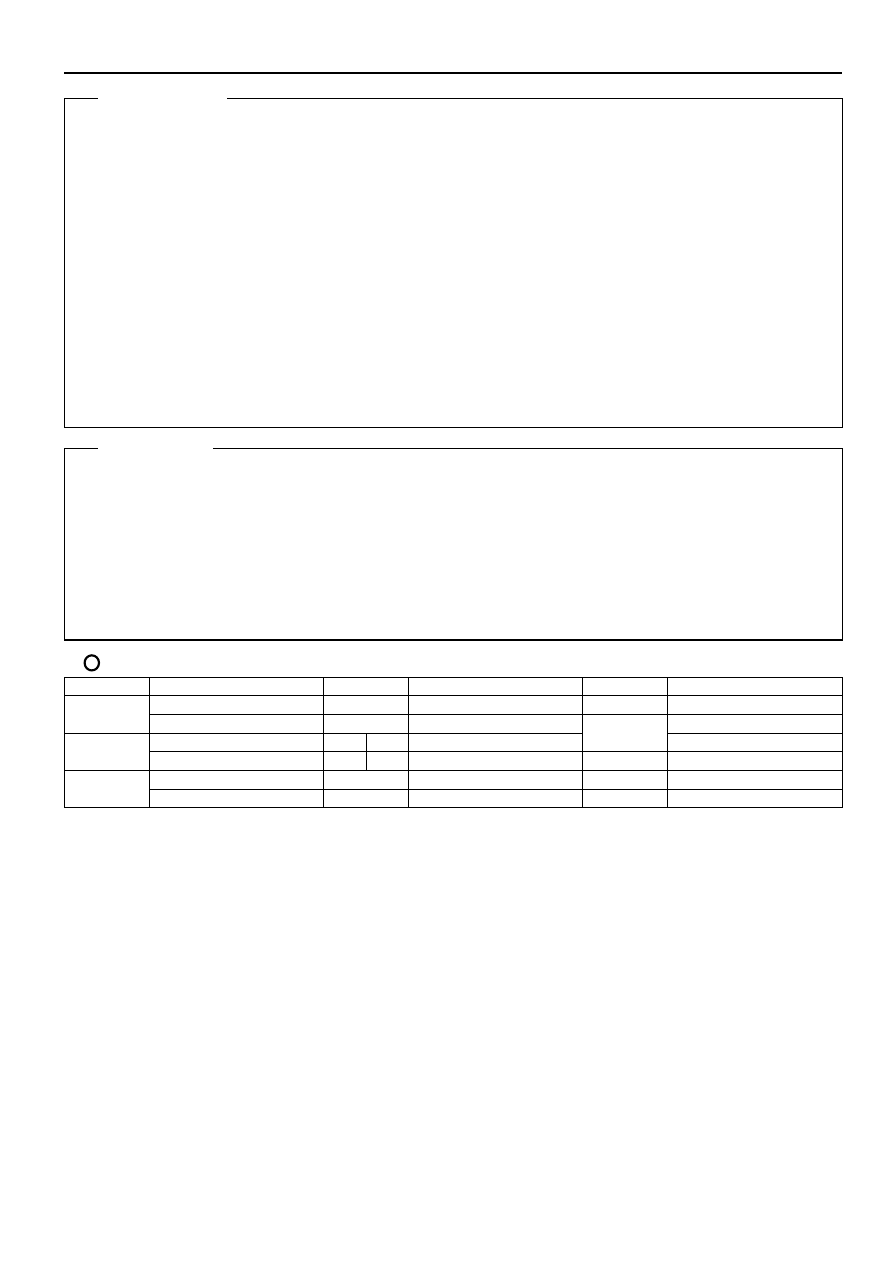
: Parts Location
Code
See Page
Code
See Page
Code
See Page
A4
A32
P3
A4
A33
S1
A6
C7
A
S1
A6
C8
B
S14
A7
D3
A7
J7
System Outline
Service Hints
2002 CAMRY (EWD461U)
177
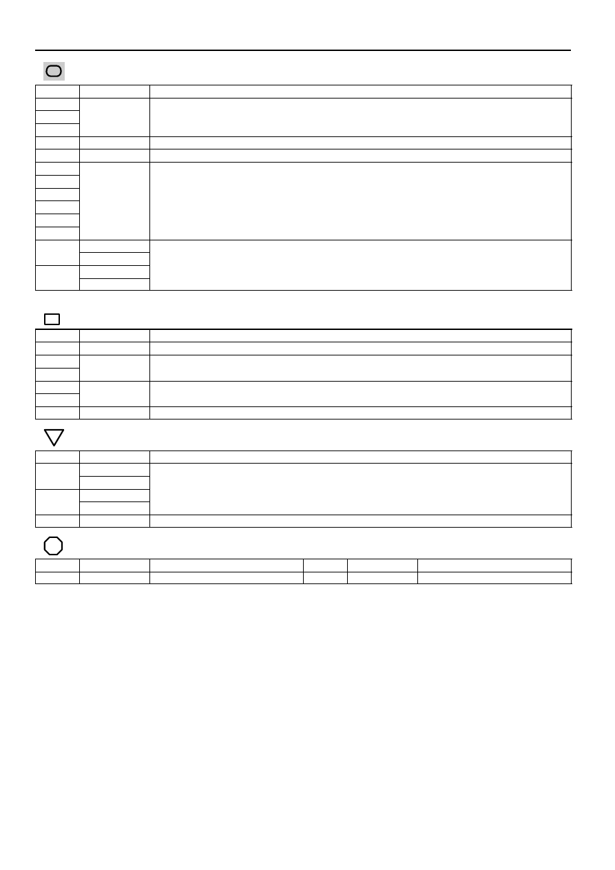
: Junction Block and Wire Harness Connector
Code
See Page
Junction Block and Wire Harness (Connector Location)
1C
1E
Engine Room Main Wire and Engine Room J/B (Engine Compartment Left)
1G
g
g
(
g
)
2B
Instrument Panel Wire and Driver Side J/B (Lower Finish Panel)
2G
Engine Room Main Wire and Driver Side J/B (Lower Finish Panel)
2L
2M
2O
Instrument Panel Wire and Driver Side J/B (Lower Finish Panel)
2P
Instrument Panel Wire and Driver Side J/B (Lower Finish Panel)
2R
2S
3A
3A
Instrument Panel Wire and Passenger Side J/B (Instrument Panel Brace RH)
3B
Instrument Panel Wire and Passenger Side J/B (Instrument Panel Brace RH)
3B
∗
1 : TMC Made Automatic A/C
∗
2 : TMC Made Manual A/C
: Connector Joining Wire Harness and Wire Harness
Code
See Page
Joining Wire Harness and Wire Harness (Connector Location)
ID1
Engine Room Main Wire and Floor Wire (Left Side of Driver Side J/B)
IF3
Engine Room Main Wire and Instrument Panel Wire (Right Side of Steering Column Tube)
IF4
Engine Room Main Wire and Instrument Panel Wire (Right Side of Steering Column Tube)
IL1
Engine Wire and Instrument Panel Wire (Behind the Glove Box)
IL2
Engine Wire and Instrument Panel Wire (Behind the Glove Box)
IN2
Instrument Panel Wire and Floor No.2 Wire (Right Kick Panel)
: Ground Points
Code
See Page
Ground Points Location
EA
EA
Right Fender
EB
Right Fender
EB
II
Cowl Side Panel LH
: Splice Points
Code
See Page
Wire Harness with Splice Points
Code
See Page
Wire Harness with Splice Points
E3
Engine Room Main Wire
E3
Engine Room Main Wire
Wyszukiwarka
Podobne podstrony:
ABS Octawia 1999
Flatten Your Abs
Badanie uk prcent C5 prcent 82adu ABS
05 Streszczenie TMC
07 Streszczenie TMC
ABS Ćwiczenie mięśni brzucha
DEMONTAŻ MONTAŻ KALKULATOR ABS
28 układ ABS
2 abs
ABS in 8min
pytania TMC, pytania sprezarka, Laboratorium „Termodynamika”
Absorbcja promieniowania gamma, ABS G TY, POLITECHNIKA SLASKA
ABS,EDS,ASR,ESP od98
ABS control
ABS wersia D Cab r1 2[1]
ABS TMMK
07 Streszczenie TMC
więcej podobnych podstron