
Editing the Toolpath
Please note that these options are only available in the milling and turning environment
Several commands allow you to edit the toolpath itself. These can be selected from Toolpath (Edit menu):
Section - Changes a toolpath section.
Split - Breaks up a toolpath.
Delete - Deletes a toolpath section.
Note that once a toolpath has been edited using one of these commands, it is no longer a normal machining
instruction and cannot be edited or regenerated.
Toolpaths that have been edited will be shown with an appropriate comment after the command name in
the instruction list.
1
EdgeCAM User Guide

Editing the Toolpath
Please note that these options are only available in the milling and turning environment
Several commands allow you to edit the toolpath itself. These can be selected from Toolpath (Edit menu):
Section - Changes a toolpath section.
Split - Breaks up a toolpath.
Delete - Deletes a toolpath section.
Note that once a toolpath has been edited using one of these commands, it is no longer a normal machining
instruction and cannot be edited or regenerated.
Toolpaths that have been edited will be shown with an appropriate comment after the command name in
the instruction list.
Deleting a Section of a Toolpath
The command Toolpath Delete (Edit menu) lets you remove part of a toolpath between two selected
points. The system then creates a linear tool move to link the two parts of the toolpath.
Link Control – (Milling only) Specifies how the link moves are to be created. Select Shortest to create a
single linear move. Select Retract to create a vertical move to the Retract plane (defined below) before
adding a link move.
Depth Parameters – (Milling only) Specifies the Clearance and Retract depth levels used by the system to
generate the link moves.
Screen Snap – Check this box to select a toolpath from the screen rather than a command from the
instruction list.
2
EdgeCAM User Guide

Editing the Toolpath
Please note that these options are only available in the milling and turning environment
Several commands allow you to edit the toolpath itself. These can be selected from Toolpath (Edit menu):
Section - Changes a toolpath section.
Split - Breaks up a toolpath.
Delete - Deletes a toolpath section.
Note that once a toolpath has been edited using one of these commands, it is no longer a normal machining
instruction and cannot be edited or regenerated.
Toolpaths that have been edited will be shown with an appropriate comment after the command name in
the instruction list.
Editing a Section of a Toolpath
The command Toolpath Section (Edit menu) lets you change part of a toolpath between two selected
points.
Location – Check this box to move a node on the toolpath. If you reposition an arc move, it will change into
a linear move.
Feedrate – Specify the tool feedrate in the workplane for the selected part of the toolpath.
Plunge Feed – (Milling only) Specify the vertical tool feedrate (into and out of the workplane) for the
selected part of the toolpath.
Speed – Specify the spindle speed to be used during the selected part of the toolpath.
Rapid – Check this box to change the selected part of the toolpath to all rapid moves.
Screen Snap – Check this box to select the toolpath from the screen rather than from the instruction list.
3
EdgeCAM User Guide

Editing the Toolpath
Please note that these options are only available in the milling and turning environment
Several commands allow you to edit the toolpath itself. These can be selected from Toolpath (Edit menu):
Section - Changes a toolpath section.
Split - Breaks up a toolpath.
Delete - Deletes a toolpath section.
Note that once a toolpath has been edited using one of these commands, it is no longer a normal machining
instruction and cannot be edited or regenerated.
Toolpaths that have been edited will be shown with an appropriate comment after the command name in
the instruction list.
Splitting a Toolpath
The command Toolpath Split (Edit menu) lets you break a toolpath at a selected point to produce two
separate toolpaths. This lets you insert new commands between the two toolpaths.
Screen Snap – Check this box to select a toolpath from the screen rather than a command from the
instruction list. The toolpath will then be broken at the point nearest to the digitised point on the screen.
4
EdgeCAM User Guide
Editing the Toolpath
Please note that these options are only available in the milling and turning environment
Several commands allow you to edit the toolpath itself. These can be selected from Toolpath (Edit menu):
Section - Changes a toolpath section.
Split - Breaks up a toolpath.
Delete - Deletes a toolpath section.
Note that once a toolpath has been edited using one of these commands, it is no longer a normal machining
instruction and cannot be edited or regenerated.
Toolpaths that have been edited will be shown with an appropriate comment after the command name in
the instruction list.
Transforming the Toolpaths
Several commands are available to copy or alter one or more machining operations from the instruction list.
Note that only the toolpaths are altered by these commands – there is no alteration of the original design
geometry.
These commands copy and transform the calculated toolpath. They do not regenerate the path in its new
position. This means that fixed points such as home or toolchange positions and moves to Z clearance may
not give the desired output. Such moves should not be included in the instructions to be transformed.
Subroutines used for repeating the hole cycle positions may also be invalidated as they will no longer have
unique identifying numbers.
These are the Edit menu commands (in Manufacture Mode):
Transform Mirror – (Milling and Wire only) Check to reverse the order of the sequence and the direction of
the tool along the toolpath on the mirrored instructions.
Note that this literally reverses the direction and
that the tool will cut in the opposite direction. If multiple passes have been made, the Reverse command will
cause the last pass to be cut first.
On simple toolpaths the Reverse command will allow the climb/upcut conditions to be maintained on a
mirrored toolpath.
Transform Repeat – (Milling only) Copies the toolpath at successive depths.
Transform Rotate – (Milling and Wire only) Rotates or copies a series of operations one or more times
about a selected point. This is used where the same feature appears several times about a central point.
5
EdgeCAM User Guide
Editing the Toolpath
Please note that these options are only available in the milling and turning environment
Several commands allow you to edit the toolpath itself. These can be selected from Toolpath (Edit menu):
Section - Changes a toolpath section.
Split - Breaks up a toolpath.
Delete - Deletes a toolpath section.
Note that once a toolpath has been edited using one of these commands, it is no longer a normal machining
instruction and cannot be edited or regenerated.
Toolpaths that have been edited will be shown with an appropriate comment after the command name in
the instruction list.
Transform Translate – Moves or copies a series of operations one or more times. This is used where the
same feature appears more than once in a component.
Changes have been made in EdgeCAM 7.00 to the way in which the Translate command works,
particularly for controller subroutines. These changes result in a better correlation between the moves
shown by EdgeCAM graphics and the toolpath on the machine tool. See Notes on Translate Command.
In Wire Erosion, you may only translate the toolpath in the X and Y directions.
6
EdgeCAM User Guide

Editing the Toolpath
Please note that these options are only available in the milling and turning environment
Several commands allow you to edit the toolpath itself. These can be selected from Toolpath (Edit menu):
Section - Changes a toolpath section.
Split - Breaks up a toolpath.
Delete - Deletes a toolpath section.
Note that once a toolpath has been edited using one of these commands, it is no longer a normal machining
instruction and cannot be edited or regenerated.
Toolpaths that have been edited will be shown with an appropriate comment after the command name in
the instruction list.
Notes on Translate Command
Changes have been made in EdgeCAM 7.00 to the way in which the Translate command works, particularly
for controller subroutines. These changes result in a better correlation between the moves shown by
EdgeCAM graphics and the toolpath on the machine tool.
Translated moves
EdgeCAM translates the toolpath as represented by move end points within the designated labels. From a
machine tool point of view the "Start" of a sub-routine is, therefore, the End of the move leading to that first
endpoint. Slightly different results will be seen depending on the type of move. A direct rapid or feed move
will result in its end point being the subroutine start and the move will effectively be "lost" in repeats of the
subroutine. A 2D rapid, doglegged, move (e.g. XY and then Z) will give the dogleg point as subroutine start
and only the first segment of the move will be lost.
Note that the graphics often show an apparent dogleg when resolved rapids are not used. This intermediate
point does not exist on the NC data - it is purely for visualisation purposes - and will not be used as a start
point.
Some previous changes in this area have been removed from EdgeCAM. This means that in some cases
the graphical representation will change, compared to previous versions, to more closely represent what
happens on the machine tool.
Good practice
For safety reasons, subroutines should always start and finish at a safe clearance height. If this practice is
followed then the link moves between subroutines can be expected to also be at the safe height. The
subroutine should always include the liftout move at the end of a cut.
A specific move to a point near to the required start of the subroutine before defining the subroutine is
recommended. This is generally preferable to making a move direct from, say, toolchange and relying on
the 2D rapid's dogleg to be the start point. If the machine tool movements are not exactly as represented on
screen then this will minimise the discrepancy.
Code Generators
Some additional system variables have been added to the Code Generator to pass the subroutine start
point.
In macros TRANSLATE and RESET, the variables XEND, YEND, ZEND now represent the end of
any approach move and thus the start of the subroutine.
In macros SUBSTART and SUBCALL, the existing variables NEXTXMOVE, NEXTYMOVE,
NEXTZMOVE can be used.
The TRANSLATE Macro (No. 32) should now use XEND etc. as subroutine start point instead of
XSUB etc. Rapid approach moves to this point should be output.
The SUBSTART Macro (No. 55 ) should use NEXTXMOVE etc. as a "HOLD" point for calculation of
incremental moves.
The SUBCALL Macro (No. ) should include a rapid approach move to NEXTXMOVE etc.
Existing code generator files will continue to work as before since no existing variables have been changed.
It may be, however, that their actions are not correctly represented on screen by EdgeCAM graphics.
The Code Wizard templates for milling and turning have been updated to match the graphics. Template
based code generators should be updated to the version 7.00 templates to take advantage of these
changes.
The templates have also been updated to make the switch between incremental and absolute subroutines
easier. The logic within the template will now determine whether to use the Rapid or Translate code
constructors and G90/91 blocks will only be output by subroutine start and end if they are required. This last
change is within the default sequence of the code constructors. It will not be applied automatically to
updated CGD files but will be available for newly created files.
It should always be remembered that the exact action of a machine tool when using controller cycles is
beyond the control of EdgeCAM. It is the user's responsibility to ensure that his code generators are
7
EdgeCAM User Guide

Editing the Toolpath
Please note that these options are only available in the milling and turning environment
Several commands allow you to edit the toolpath itself. These can be selected from Toolpath (Edit menu):
Section - Changes a toolpath section.
Split - Breaks up a toolpath.
Delete - Deletes a toolpath section.
Note that once a toolpath has been edited using one of these commands, it is no longer a normal machining
instruction and cannot be edited or regenerated.
Toolpaths that have been edited will be shown with an appropriate comment after the command name in
the instruction list.
correctly configured and that the on-screen representation closely matches the actions of his controllers.
8
EdgeCAM User Guide

Editing the Toolpath
Please note that these options are only available in the milling and turning environment
Several commands allow you to edit the toolpath itself. These can be selected from Toolpath (Edit menu):
Section - Changes a toolpath section.
Split - Breaks up a toolpath.
Delete - Deletes a toolpath section.
Note that once a toolpath has been edited using one of these commands, it is no longer a normal machining
instruction and cannot be edited or regenerated.
Toolpaths that have been edited will be shown with an appropriate comment after the command name in
the instruction list.
Using Matrix Mode
Only available in the milling environment
Matrix Mode lets you repeat an operation or series of operations at regular intervals, specifying the number
of rows and columns you need in your grid or matrix.
EdgeCAM always displays the selected geometry in the bottom left hand corner of the Matrix. The various
elements of the matrix are machined starting from the bottom left hand corner by default. However, when
you select a tool, the Quadrant list box lets you start from the other corners of the Matrix. (Note that the
Quadrant parameter must have been enabled in your code generator for this to work.)
Matrix Mode Start (Edit menu) is used before the sequence of machining commands that are to be
matrixed.
You now perform a normal sequence of toolchanges and machining cycles on the geometry as a
single part.
Matrix Mode Finish (Edit menu) is used after you have finished entering the sequence of commands that
are to be matrixed.
Each Matrix Mode Start must be completed with a Matrix Mode Finish command.
Note that the Mode (View menu) command contains a ‘Matrix’ check box that allows you to display or hide
the Matrixed toolpath.
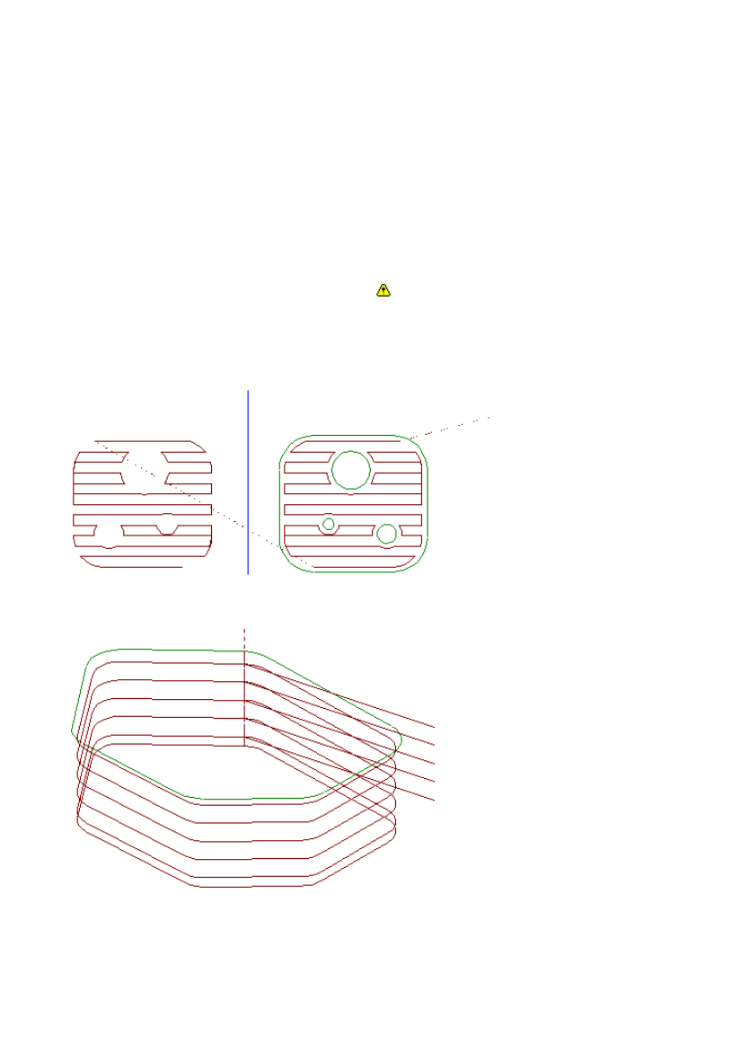
In this example, a Lacing area clearance toolpath has been created after a Matrix Mode Start.
On selecting the Matrix Mode Finish command, the Lacing toolpath is repeated in a grid according to the
parameters specified in the Matrix Mode Start command.
Repeats – Specify the number of cells in the matrix in the X and Y direction.
Fret – Specify the number of Border widths (Double or Single) separating each cell in the matrix.
Border – Specify the border spacing in part units in X and Y.
Length – Specify the distance between each cell in the matrix in X and Y.
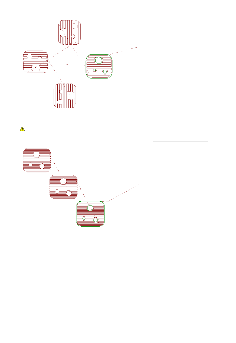
Dead Zones – Allows you to specify areas that can be used by clamps or fixturing. Define the dead zones
by nominating two sides of the matrix rectangle and a distance in from the edge.
This example has X Repeats=5 and Y Repeats=4, and a Dead Zone along the bottom right of the matrix:
Direction – Specifies which cell is to be machined after the first cell. Select between Row or Column.
Column forces the tool to move to a cell in the Y direction and Row (the default) forces the tool to move to a
cell in the X direction.
Lace Cut – Deselect to move the tool in the same direction along each row or column. The default setting of
the checked box moves the tool to the next cell with the shortest possible movement.
Subroutines – Select Pathtrace to avoid using subroutines when generating CNC code from this matrixed
toolpath. The default setting of Controller will use subroutines where available.
Define Layout – Select to ignore the Direction modifier and specify exactly in which order the individual
cells are to be machined. The system displays a diagram of the cells in the matrix. Select each cell in the
order you want the cells machined in. As each cell is selected, it is given a number to show its position in
the sequence.
9
EdgeCAM User Guide

Editing the Toolpath
Please note that these options are only available in the milling and turning environment
Several commands allow you to edit the toolpath itself. These can be selected from Toolpath (Edit menu):
Section - Changes a toolpath section.
Split - Breaks up a toolpath.
Delete - Deletes a toolpath section.
Note that once a toolpath has been edited using one of these commands, it is no longer a normal machining
instruction and cannot be edited or regenerated.
Toolpaths that have been edited will be shown with an appropriate comment after the command name in
the instruction list.
Copyright
(C)1988-2005 Pathtrace Engineering Systems. All rights reserved.
Pathtrace Engineering Systems and its registered resellers or sub-resellers shall have no liability or
responsibility to the licensee or any other person or entity with respect to any liability, loss or damage
caused or alleged to be caused directly or indirectly by this product, including but not limited to any
interruption of service, loss of business or anticipatory profits or consequent damages resulting from the use
or operation of this software.
Microsoft, Windows and Windows NT are registered trademarks of Microsoft Corporation.
MemoHASP is a registered trademark of Aladdin Knowledge Systems Ltd.
NetSentinel is a trademark of Rainbow Technologies, Inc.
OpenGL(r) and Optimizer are trademarks of Silicon Graphics Inc.
Parasolid is a trademark of Unigraphics Solutions Inc.
Autodesk Inventor (tm) is a trademark of Autodesk Inc.
SolidWorks is a registered trademark of SolidWorks Corporation.
Solid Edge is a registered trademark of EDS Inc.
PTC, Pro/DESKTOP, Pro/ENGINEER(r), GRANITE (tm) One, are trademarks or registered trademarks of
Parametric Technology Corporation or its subsidiaries in the U.S. and in other countries.
AutoCAD and DXF are registered trademarks of Autodesk Inc.
MicroStation is a trademark of Bentley Systems Inc., an affiliate of Intergraph Corporation.
IGDS is a trademark of Intergraph Corporation.
EdgeCAM Simulator and EdgeCAM Verify use technology developed by Lightworks Designs Ltd.
ACIS is a trademark of Spatial Technology, Inc., and was developed in co-operation with Three-Space, Ltd.,
Cambridge, England, and Applied Geometry Corporation, Seattle, Washington.
Other brands and product names are trademarks of their respective owners.
The information contained within this document is subject to change without notice and does not represent
a commitment on the part of the vendor. The software described in this document is furnished under a
licence agreement and may only be used or copied only in accordance with the terms of the agreement.
Pathtrace Engineering Systems
45 Boulton Road · Reading · Berkshire · England · RG2 0NH
Telephone +44 (0)118 975 6084 · Facsimile +44 (0)118 975 6143
10
EdgeCAM User Guide
Document Outline
- Editing the Toolpath
Wyszukiwarka
Podobne podstrony:
Czasowniki modalne The modal verbs czesc I
The American Society for the Prevention of Cruelty
Christmas around the world
The uA741 Operational Amplifier[1]
The law of the European Union
Parzuchowski, Purek ON THE DYNAMIC
A Behavioral Genetic Study of the Overlap Between Personality and Parenting
How to read the equine ECG id 2 Nieznany
Pirates of the Spanish Main Smuggler's Song
Magiczne przygody kubusia puchatka 3 THE SILENTS OF THE LAMBS
hawking the future of quantum cosmology
An%20Analysis%20of%20the%20Data%20Obtained%20from%20Ventilat
Jacobsson G A Rare Variant of the Name of Smolensk in Old Russian 1964
OBE Gods of the Shroud Free Preview
Posterior Capsular Contracture of the Shoulder
Fallow the Leader
LotR The Ruins of Annuminas
więcej podobnych podstron