Teachware
CNC Technology
Contents

CNC Basics -
Excerpt
MTS TeachWare Student’s Book - © MTS GmbH 1999
MTS Mathematisch Technische Software-Entwicklung GmbH • Kaiserin-Augusta-Allee 101 • D-10553 Berlin
Phone: +49 / 30 / 349 960 - 0 • Fax: +49 / 30 / 349 960 -25 • World Wide Web: http://www.mts-cnc.com • email: mts@mts-cnc.com
Introduction into CNC Technology
© MTS GmbH 1997
11
1.3
Characteristics of modern CNC machine tools
Controllable feed and rotation axis
Work part machining on CNC machine tools requires controllable and adjustable infeed axes which are run
by the servo motors independent of each other. The hand wheels typical of conventional machine tools are
consequently redundant on a modern machine tool.
CNC lathes (see figure 3) have at least 2 controllable or adjustable feed axes marked as X and Z.
X
Z
Figure 3
Controllable NC axes on an automatic lathe
CNC- milling machines (see figure 4) on the other hand have at least 3 controllable or adjustable feed axes
marked as X, Y, Z.
Z
Y
X
Figure 4
Controllable NC axes on a milling machine
Introduction into CNC Technology
© MTS GmbH 1997
16
In CNC milling the main function of the work part clamping devices is the correct positioning of the work
parts. The work part clamping should allow a work part change which is as quick, easy to approach, correctly
and exactly positioned, reproducible as possible. For simple machining controllable, hydraulic chuck jaws are
sufficient. For milling on all sides the complete machining should be possible with as few re-clamping as pos-
sible. For complicated milling parts milling fixtures, also with integrated automatic rotation, are being manu-
factured or built out of available modular systems to allow, as far as possible, complete machining without re-
clamping. Work part pallets, which are loaded with the next work part by the operator outside the work room
and then automatically taken into the right machining position, are increasingly being used.
Tool change facilities
Figure 12
Example of a turret
CNC tool machines are equipped with controllable
automatic tool change facilities. Depending on the
type and application area these tool change facilities
can simultaneously take various quantities of tools
and set the tool called by the NC program into work-
ing position. The most common types are:
•
the tool turret
•
the tool magazine.
The tool turret (see figure 12) is mostly used for
lathes and the tool magazine for milling machines.
If a new tool is called by the NC program the turret
rotates as long as the required tool achieves working
position. Presently such a tool change only takes
fractions of seconds.
Depending on the type and size, the turrets of the CNC machines have 8 to 16 tool places. In large milling
centers up to 3 turrets can be used simultaneously. If more than 48 tools are used tool magazines of different
types are used in such machining centers allowing a charge of up to 100 and even more tools. There are
longitudinal magazines, ring magazines, plate magazines and chain magazines (see figure 13) as well as
cassette magazines.
Figure 13
Example of a chain magazine
Introduction into CNC Technology
© MTS GmbH 1997
17
1
2
3
4
Figure 14
Automatic tool change facility
milling tools
tool gripper (tool changer)
work spindle
tool magazine
In the tool magazine the tool change takes place using a gripping system also called tool changer (see figure
14). The change takes place with a double arm gripping device after a new tool has been called in the NC
program as follows:
•
Positioning the desired tool in magazine into tool changing position
•
Taking the work spindle into changing position
•
Revolving the tool gripping device to the old tool in the spindle and to the new tool in the magazine
•
Taking the tools into the spindle and magazine and revolving the tool gripping device
•
Placing the tools into the spindle sleeve or magazine
•
Returning the tool gripping device into home position
The tool change procedure takes between 6 to 15 seconds, whereby the quickest tool changers are able to
make the tool change in merely one second.
Security precautions on CNC machine tools
The target of work security is to eliminate accidents and damages to persons, machines and facilities at work
site.
Basically the same work security precautions apply to working on CNC machines as to conventional machine
tools. They can be classified in three categories:
•
Danger elimination
Defects on machines and on all devices necessary for work need to be registered at once.
Emergency exits have to be kept free.
No sharp objects should be carried in clothing.
Watches and rings are to be taken off.
•
Screening and marking risky areas:
The security precautions and corresponding notifications are not allowed to be removed or inacti-
vated.
Moving and intersecting parts must be screened.
•
Eliminating danger exposure
Protective clothing must be worn to protect from possible sparks and flashes.
Protective glasses or protective shields must be worn to protect the eyes.
Damaged electrical cables are not allowed to be used.
Basic Geometry for CNC Machining
© MTS GmbH 1997
24
Coordinate system definition with reference to machine or work part
Machine coordinate system
The machine coordinate system of the CNC machine tool is defined by the manufacturer and cannot be
changed. The point of origin for this machine coordinate system, also called machine zero point M, cannot be
shifted in its location (see figure 21).
Work part coordinate system
The work part coordinate system is defined by the programmer and can be changed. The location of the point
of origin for the work part coordinate system, also called work part zero point W, can be specified as desired
(see figure 22).
M
X
Y
Z
M Machine zero point
X
Y
Z
W
W Work part zero point
Figure 21
Machine coordinate system
Figure 22
Work part coordinate system
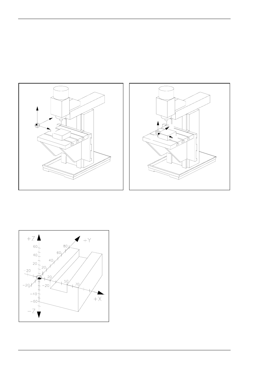
CNC milling machine
The design of the CNC machine specifies the definition of the respective coordinate system. Correspond-
ingly, the Z axis is specified as the working spindle (tool carrier) in CNC milling machines (see figure 23),
whereby the positive Z direction runs from the work part upwards to the tool.
Figure 23
Milling part in three-dimensional Cartesian coordinate
system
The X axis and the Y axis are usually parallel to
the clamping plane of the work part.
When standing in front of the machine the positive
X direction runs to the right and the Y axis away
from the viewer.
The zero point of the coordinate system is rec-
ommended to be placed on the outer edge of the
work part.
Basic Geometry for CNC Machining
© MTS GmbH 1997
25
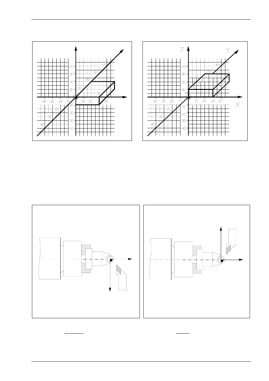
For an easier calculation of the points needed for programming it is advisable to use the outer edges of the
upper (see figure 24) or the lower area (see figure 25).
X
Y
Z
Figure 24
Work part zero point in the upper left outer edge
Figure 25
Work part zero point in the lower left outer edge
CNC lathes
In the CNC lathes the working spindle (tool carrier) is specified as Z axis. This means the Z axis is identical to
the rotation axis (see figure 26 and 27). The direction of the Z axis is specified so that the tool withdraws from
the work part when moving to the positive axis direction.
The X axis is located in a right angle to the Z axis. However, the direction of the X axis always depends on if
the tool is located in front of (see figure 26) or behind (see figure 27) the rotation center.
W
+ X
+ Z
W
+ X
+ Z
Figure 26
Milling work part in Cartesian coordinate system
with 2-axis tool in front of the rotation center
Figure 27
Milling work part in Cartesian coordinate system
with 2-axis tool behind the rotation center
Basic Geometry for CNC Machining
© MTS GmbH 1997
38
2.3
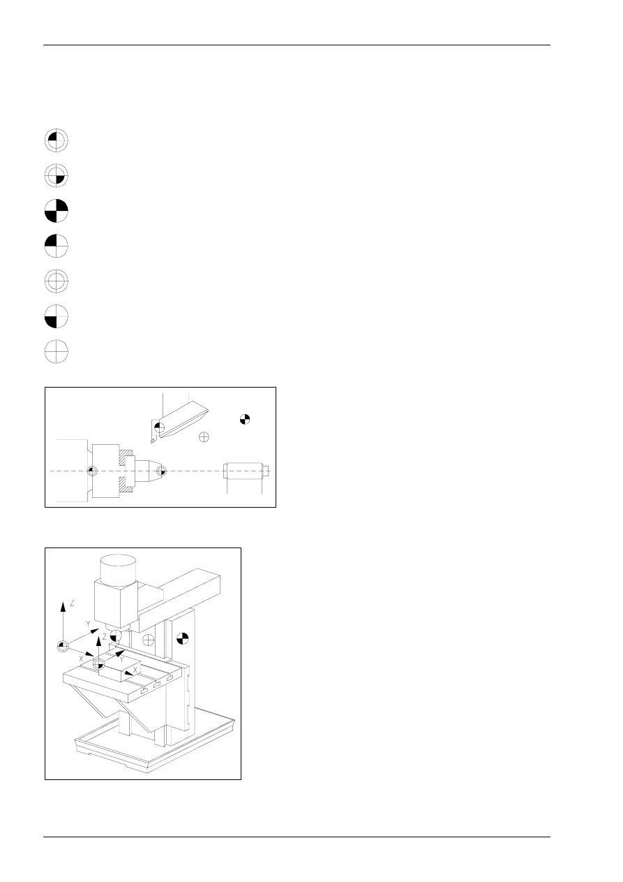
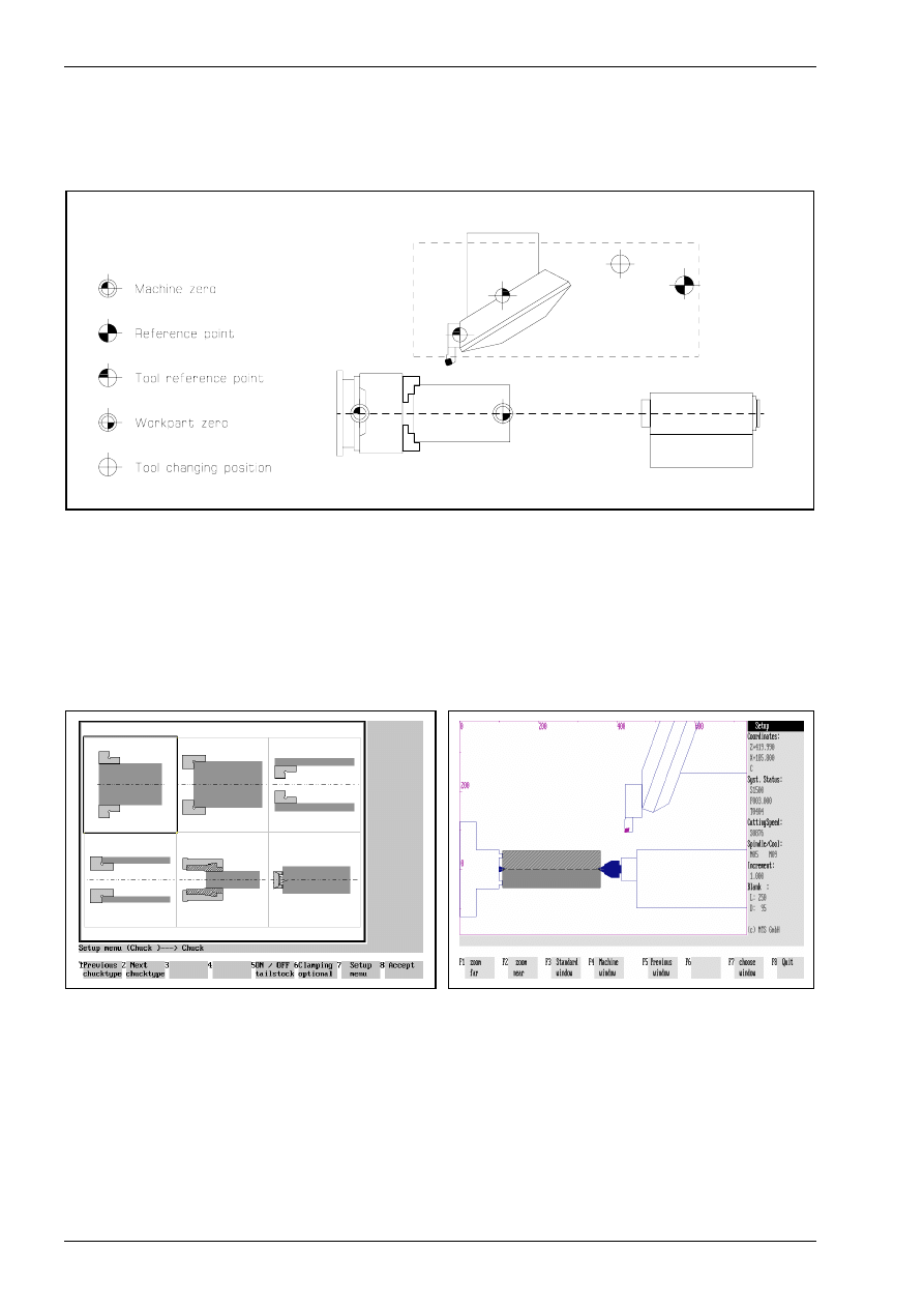
Zero and reference points on CNC machine tools
Types of zero and reference points
M
machine zero point
W
work part zero point
R
reference point
E
tool reference point
B
tool setup point
A
tool shank point
N
tool change point
E
R
N
W
M
Figure 43
Location of the zero and reference points for turning
Machine zero point M
Each numerically controlled machine tool works with
a machine coordinate system. The machine zero
point is the origin of the machine-referenced coordi-
nate system. It is specified by the machine manufac-
turer and its position cannot be changed. In general,
the machine zero point M is located in the center of
the work spindle nose for CNC lathes and above the
left corner edge of the work part carrier for CNC verti-
cal milling machines.
R
N
W
A
M
Figure 44
Location of the zero and reference point for milling
Reference point R
A machine tool with an incremental travel path meas-
uring system needs a calibration point which also
serves for controlling the tool and work part move-
ments. This calibration point is called the reference
point R. Its location is set exactly by a limit switch on
each travel axis. The coordinates of the reference
point, with reference to the machine zero point, al-
ways have the same value. This value has a set ad-
justment in the CNC control. After switching the ma-
chine on the reference point has to be approached
from all axes to calibrate the incremental travel path
measuring system.
Basic Geometry for CNC Machining
© MTS GmbH 1997
45
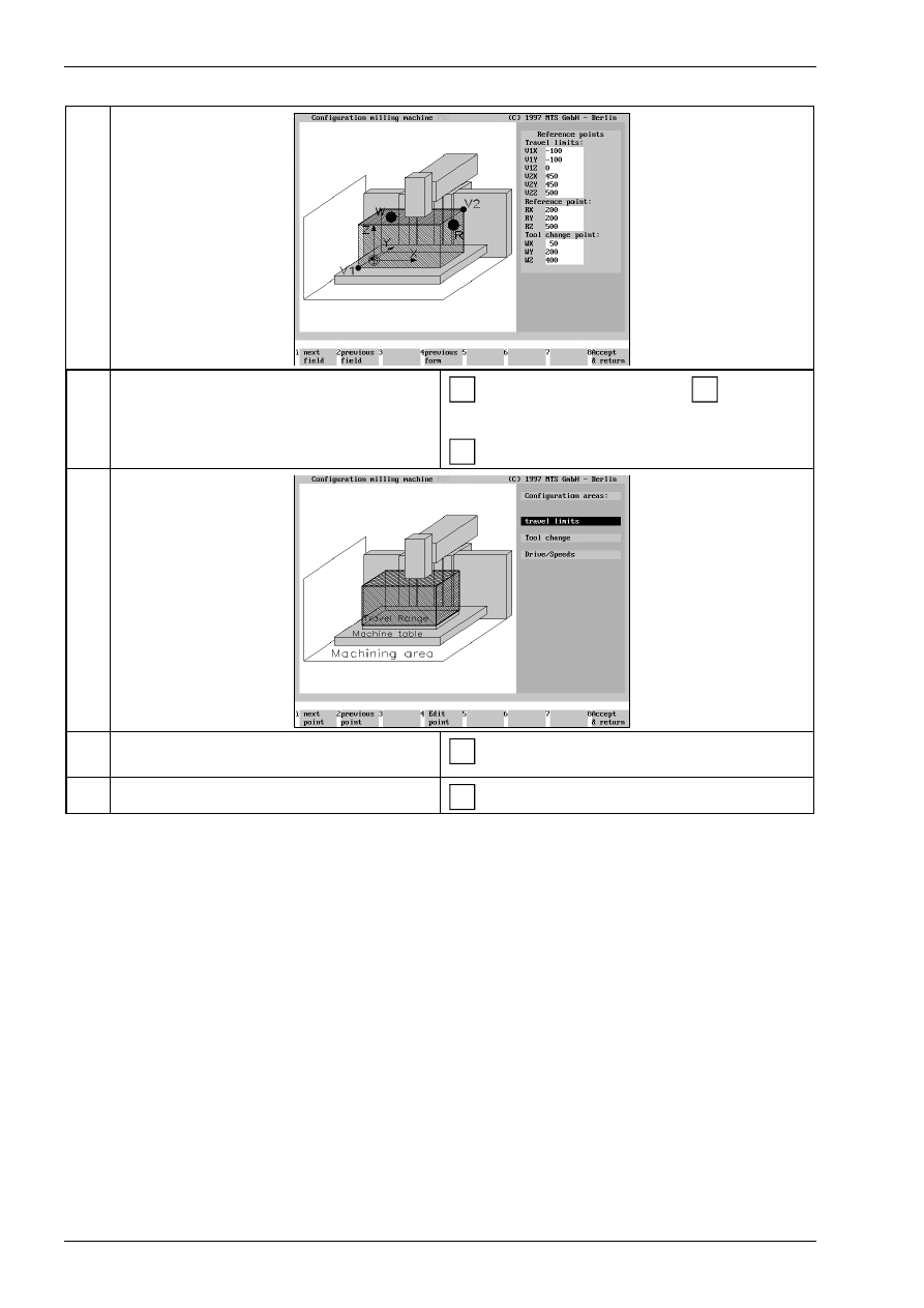
CNC exercise
Generating the machine room of a CNC milling machine
Description
Entry
1. Call the configuration in the main menu.
F5
(Configuration)
2. Select the MTS milling machine.
F1
or select
F2
3. Call the configuration management.
F5
(Config managm)
4. Generate a new configuration.
F1
(Generate)
5. Enter a new name, e.g. FS2.
F8
use the keyboard to type the new name „FS2“.
(generate)
6. Select default values,
for example, MAKINO FX 650
F8
or select
(Default data)
7. Select the configuration point „machine room“.
F1
or select
F2
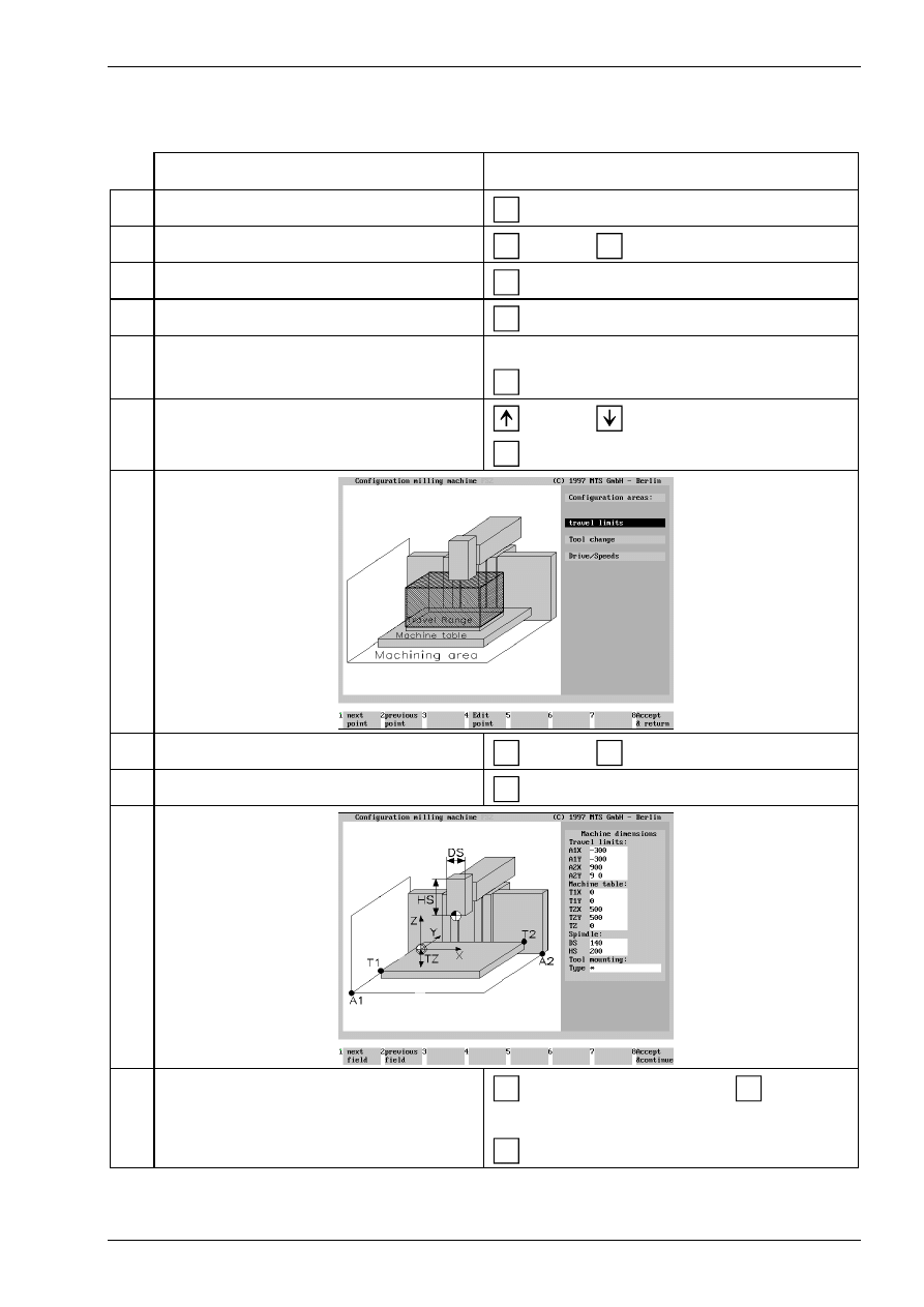
8. Change the machine room data.
F4
(Edit point)
9. Enter the machine room data.
F1
F8
or select the individual points
F2
Use the keyboard to type in the values.
(Accept & Continue)
Basic Geometry for CNC Machining
© MTS GmbH 1997
46
10. Enter the data for the reference points.
F1
F8
or select the individual points
F2
Use the keyboard to type in the values.
(Accept & Continue)
11. Quit the menu configuration for milling ma-
chine.
F8
(Accept & Return)
12. Quit the main menu „configuration“
F8
(Accept & Terminate)
Basic Geometry for CNC Machining
© MTS GmbH 1997
60
2.5
Tool Compensations for CNC Machining
Using tool compensation values
Using the tool compensation values it is easy to program a work part without consideration of the actually
applicable tool lengths or tool radii. The available work part drawing data can be directly used for program-
ming. The tool data, lengths as well as radii of the milling machines or indexable inserts are automatically
considered by the CNC control.
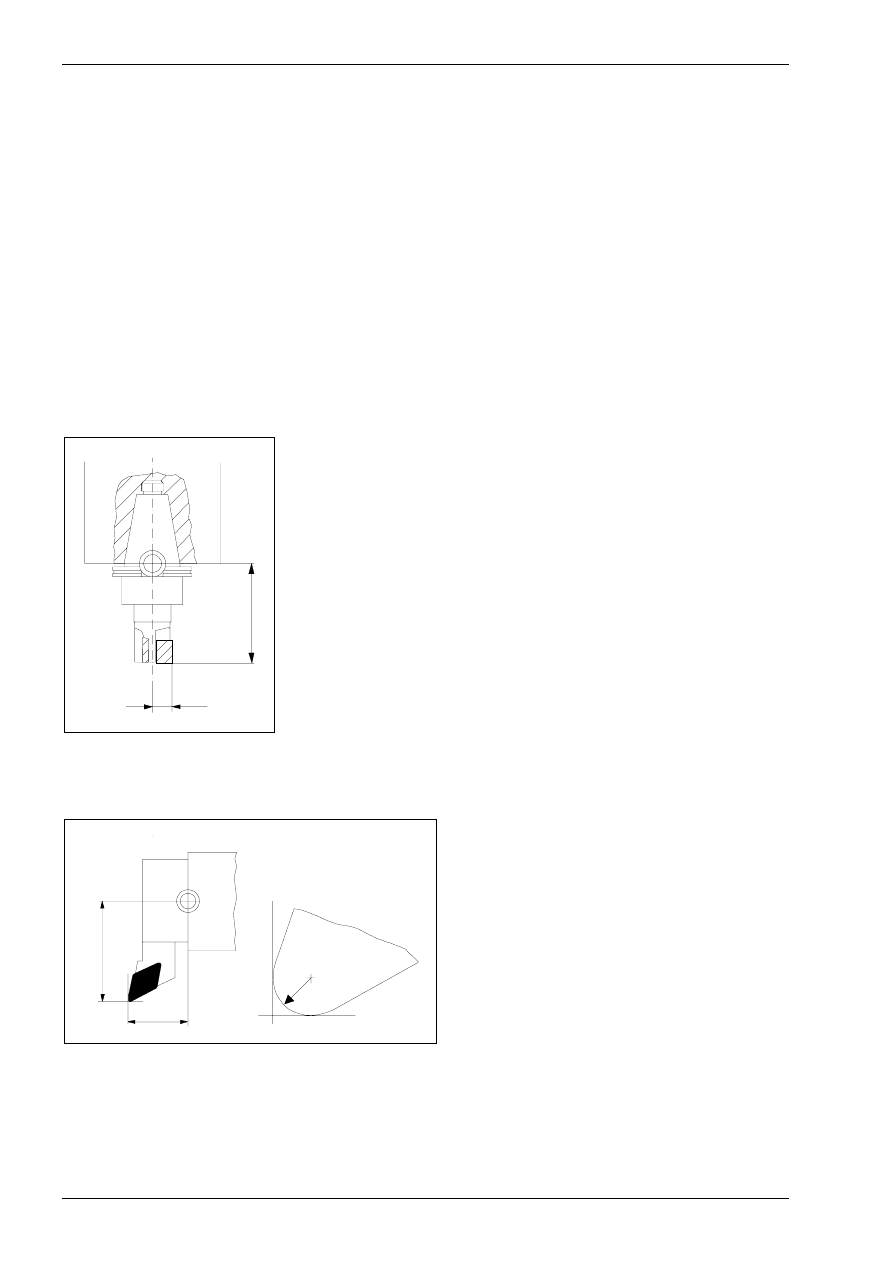
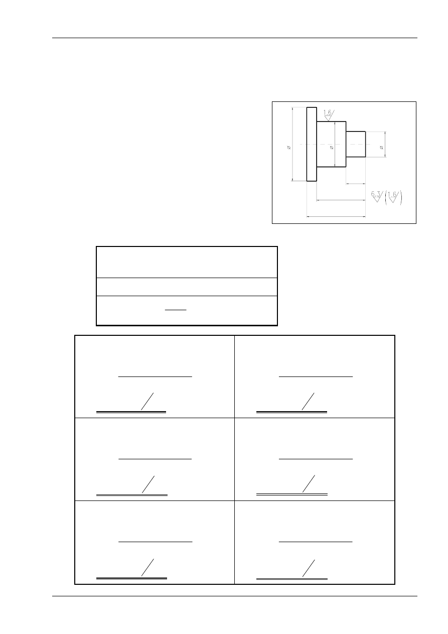
Tool length compensation for milling and turning
A tool length compensationregarding the reference point enables the adjustment between the set and actual
tool length, as in case of tool finishing. This tool length value has to be available for the control. For this it is
necessary to measure the length L, i.e. the distance between the tool setup point B and the cutting tip, and to
enter it into the control (see chapter on tool measuring page 67 ff.).
In case of milling tools the length is defined in Z direction (see figure 71).
B
R
L
Figure 71
Tool compensation values on a cutting tool
B
tool setup point
L
length = distance of the cutting tip to the tool
setup point in Z
R
radius of the milling tool
In case of lathe tools the length L is defined in Z direction (see figure 72).
B
R
Q
L
Figure 72
Tool compensation values on a lathe tool
B
tool setup point
L
length = distance of the cutting tip to the tool
set-in point in Z
Q
overhang = distance of the cutting tip to the
tool setup point in X
R
cutting radius
In the CNC control these tool compensation values are stored in the compensation value storage, whereby in
most CNC controls it is possible to describe up to 99 tools. These values have to be activated during ma-
chining. This is done by calling the data within the NC program, e.g. with the address H or by specific places
in the T word.
Basic Geometry for CNC Machining
© MTS GmbH 1997
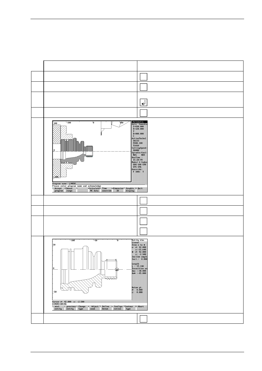
81
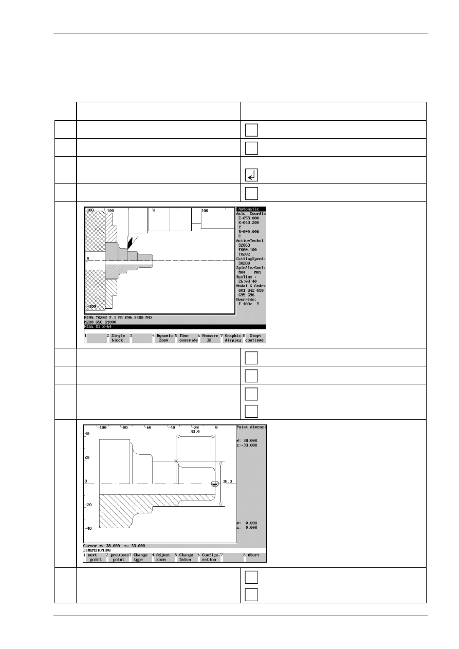
Measuring the work part
A work part can be measured either after machining (automatic run) or during machining after each machin-
ing step (in single block run).
Procedure:
Description
Entry
1. Call CNC turning in the main menu.
F1
(Turning)
2. Select automatic run.
F3
(Automatic mode)
3. Call a stored NC program, e.g. GEWBU2.
Type „GEWBU2“ using the keyboard and
confirm.
4. Select simulation mode for automatic run.
F1
(Automatic mode)
Machining is simulated on the screen
5. Select measuring menu.
F6
(Dimension 3D)
6. Select the menu for entity measuring.
F6
(Entity dimension)
7. Select the entity to be measured.
F1
F2
(next entity) or
(previous entity)
The data for the selected entity are dis-
played in each case.
8. Quit the menu for entity measuring.
F8
(Abort)
Basic Geometry for CNC Machining
© MTS GmbH 1997
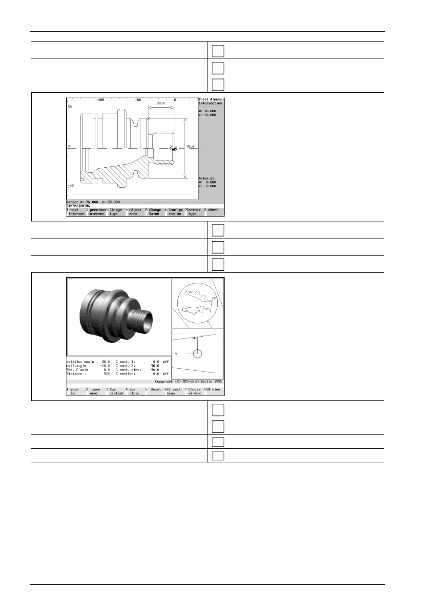
82
9. Select menu for point dimensioning.
F7
(Point dimension)
10. Select the point to be measured.
F1
F2
(next point) or
(previous point)
The data of the selected point are dis-
played in each case.
11. Quit the menu for point measuring.
F8
(Abort)
12. Select the menu for 3D representation.
F1
(3D display)
13. Generate the 3D representation.
F8
(3D view)
14. Quit the menu for 3D representation.
ESC
ESC
15. Quit the measuring menu.
F 8
(Quit)
16. Quit the simulation mode of automatic run.
F 8
(Quit)
Technological Basics for CNC Machining
© MTS GmbH 1997
92
Cutting edge geometry
Each machining process requires its cutting edge geometry. Only this can guarantee ideal production times,
long cutting-edge life and high surface quality. The angles of the tool cutting edge play a decisive role here
(vgl. Abbildung 103).
α
0
β
0
γ
0
χ
r
ε
r
λ
s
α
0
clearance angle
β
0
wedge angle
γ
0
angle of rake
ε
r
angle of point
λ
s
angle of inclination
χ
r
adjustment angle
Figure 103
Cutting geometries in turning
Clearance angle
α
:
The clearance angle reduces friction and heating up of the tool edge and the work
part.
Wedge angle
β
:
The size of the wedge angle depends on the hardness and toughness of the work part.
The smaller the wedge angle the lighter the cutting, however, the larger the edge abra-
sion and the shorter the cutting edge life.
Angle of rake
γ
:
The angle of rake has an influence on chip building and cutting forces. The larger the
angle of rake the smaller the cutting force, however, cutting edge breach and abrasion
are increased because of total decarburization. Solid, medium hard materials require
an angle of rake of approx. 10°. Hard and brittle materials require a small or even a
negative angle of rake.
Adjustment angle
χ
: In the first place the entering angle has an influence on infeed force, on the forces
against the work part clamping and work part as well as on the cutting width and thick-
ness. In case of solid clamping situation an entering angle of 30 to 60° is selected.
Only for thin shafts or right angled offsets 90° is selected for the adjustment angle.
Inclination angle
λ
: For finishing a positive, for roughing a negative inclination angle is frequently selected.
When negative angles of rake are used the cutting edge tip is exposed to less stress.
When positive inclination angle is used the chip flow is directed away from the work
part.
Angle of point
ε
:
The larger the angle of point the better the stability of the tool edge and the better the
heat removal.
Technological Basics for CNC Machining
© MTS GmbH 1997
94
Cutting value
Turning is a cutting operation with a circular cutting movement and an infeed which can be in any relation to
the cutting direction. In most cases the cutting movement is made by the rotation of the work part and the
infeed of the tool (see figure 110). The
•
cutting speed v
c
and the
•
infeed speed v
f
overlap and result in a continuous cutting process.
Cutting speed v
c
Cutting speed is the movement between the tool and the work part causing only a single chip removal during
one rotation without infeed. The symbol for cutting speed is v
c
and is indicated in m/min.
In general the speed indicates the traversed path
s
within a certain period of time
t
. It is calculated as follows:
v
s
t
=
in path/time
The traversed path
s
for a work part rotation can be generated in turning using the work part diameter d on
the cutting edge tip and the constant
π
:
s
d
= π
*
in m
The starting point for the calculation of the cutting speed is now a time unit t = 1 min. The result is herewith
cutting speed v
c
:
v
d
t
c
=
π
*
in m/min
The number or work part rotations in one minute is indicated as a number of rotations n (in rotations per min-
ute):
t
n
=
1
in min
As a result the following formula is achieved for the calculation of the cutting speed v
c
:
v
d n
c
= π
* *
in m/min
v
v
f
c
n
n
number of rotations
in U/min
v
f
infeed speed
in mm/
v
c
cutting speed
in m/min
v
c
=
π
* d * n
Figure 110
Cutting values in turning
Technological Basics for CNC Machining
© MTS GmbH 1997
99
11. If required display further information on turn-
ing tool.
1) indexable inserts:
F2
(help graphic)
12. 2) tool holder:
F2
(help graphic)
13. 3) tool carrier:
F2
(help graphic)
Technological Basics for CNC Machining
© MTS GmbH 1997
106
Cutting geometry
Unlike lathe tools milling tools have several cutting edges (see figure 119). Typical of milling is the disconti-
nuous cut as each cutting edge works only for a time.
ϕ
s
e
a
d
z
f
d:
diameter of the milling tool
z:
number of teeth
f
z
:
feed per tooth
a
e
:
entering point
ϕ
S
:
entering angle
α
0
a
p
β
0
γ
0
λ
s
α
0
:
clearance angle
β
0
:
wedge angle
γ
0
:
angle of rake
λ
S
:
angle of twist of the edges
a
p
:
cutting width
Figure 119
Cutting geometry milling
Clearance angle
α
:
The clearance angle is to reduce the friction and consequently the heating of the cut-
ting edge and of the work part.
Wedge angle
β
:
The size of the wedge angle depends on the hardness of the work part. The smaller
the wedge angle the lighter the cutting, however the greater the cutting abrasion and
the shorter the cutting edge life.
Angle of rake
γ
:
The angle of rake influences cutting chip formation and cutting forces. The larger the
angle of rake of the chip the smaller the cutting force, however the risk to breach as
well as abrasion of the cutting edge are increased due to erosion.
Entering angle
ϕ
S
:
The entering angle indicates the machining path of the tool with reference to the
circumference. It depend on the size of the entering point.
Inclination angle
λ
: The size of the inclination angle influences the process of chamfering and cutting-out.
Since the inclined cutting edges are consecutively engaged the milling tool runs with
increased quietness.
Technological Basics for CNC Machining
© MTS GmbH 1997
115
3.4
Calculation of technological data for CNC machining
Calculation examples of technological data for CNC turning
1. Example:
On a CNC-lathe the sketched bolt is to be roughed as
well as finished in four cuts with cutting depths of 6; 6; 5
and 5 mm and a finishing allowance of 0,5 mm.
The cutting speed for roughing is v
cv
= 280 m/min and
for finishing v
cf
=
400 m/min.
Calculate the number of rotations for each cut.
6 0
5 0
2 0
25
70
45
Calculating the number of rotations for roughing (Cut 1-4) and for finishing (Cut 5-6)
datum:
v
cv
= 280 m/min
v
cf
= 400 m/min
unknown:
n in 1/min
valid :
n
v
d
c
= π
*
1. Cut
∅
= 58mm
v
cv
= 280 m/min
n
m
m
1
280
0 058
= π
* min* ,
n
1
1537 1
=
min
2. Cut
∅
= 46mm
v
cv
= 280 m/min
n
m
m
2
280
0 046
= π
* min* ,
n
2
1938 1
=
min
3. Cut
∅
= 36mm
v
cv
= 280 m/min
n
m
3
280m
0 036
= π
* min* ,
n
3
2476 1
=
min
4. Cut
∅
= 26mm
v
cv
= 280 m/min
n
m
m
4
280
0 026
= π
* min* ,
n
4
3428 1
=
min
5. Cut
∅
= 25 mm
v
cf
= 400 m/min
n
m
m
5
400
0 025
= π
* min* ,
n
5
5393 1
=
min
6. Cut
∅
= 45 mm
v
cf
= 400 m/min
n
m
m
6
400
0 045
= π
* min* ,
n
6
2830 1
=
min
Technological Basics for CNC Machining
© MTS GmbH 1997
125
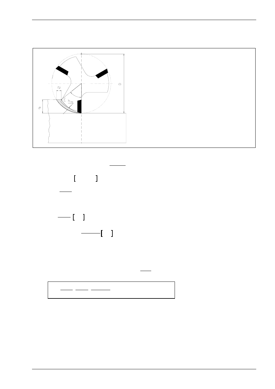
Calculating the cutting force and motor power
For calculating the cutting force, the same compensation factors are used for milling as in for turning..
ϕ
s
a
p
cutting depth
a
e
entering point
b
chip width
F
cz
cutting force per edge (mean)
ϕ
s
entering angle
h
m
middle chip thickness
f
z
feed per edge
z
number of cutter edges
z
e
number of edges in operation
D
diameter of milling cutter
λ
angle of twist of edges
κ
adjustment angle of edges
k
c
specific cutting force
k
c1-1
specific cutting force related to chip diame-
ter
b h
m
⋅
=1 mm
m
c
chip thickness index
These are either taken from a book of specifications or, as in the case of the angle of rake variation factor,
calculated with the formula
K
o
o
ok
γ
γ γ
= −
−
1
66 7
.
. For milling, the cutting force is:
F
F
z N
N
c
cz
e
=
⋅
⋅ =
1
. In this formula
z
z
e
s
= ⋅
°
ϕ
360
and
F
b h
k
cz
m
c
= ⋅ ⋅
. Herewith are
b
a
e
=
cos
λ
mm
and
h
f
a
d
mm
m
z
e
s
= ⋅
⋅
°⋅
⋅ ⋅
sin
κ
π ϕ
360
.
κ
=90°-
λ
for milling cutters with angle of twist.
Taking into account the compensation factors, the cutting force can be calculated with the formula:
F
z b h k
K
K
K
mm mm
N
mm
N
c
e
m
c
v
ver
o
= ⋅ ⋅ ⋅ ⋅
⋅
⋅
⋅
⋅
=
γ
2
and with
z b h
e
m
, ,
yields the formula
F
z
a
a
d
f
k
K
K
K
c
s
e
p
s
z
c
v
ver
o
= ⋅
°
⋅
⋅
°⋅
⋅ ⋅
⋅ ⋅
⋅ ⋅
⋅
⋅
ϕ
λ π ϕ
κ
γ
360
360
cos
sin

Introduction into NC programming
© MTS GmbH 1997
158
4.2
NC programming basics
A NC-program comprises a series of commands with which the CNC-machine tool is instructed to manufac-
ture a certain tool.
For each machining process on a CNC-machine tool, the NC-program has a command with relevant infor-
mation. These commands are alphanumerically coded, i.e. they consist of letters, numbers and characters.
NC programming standards (ISO)
The ISO-Norm 6983 strives for standardizing the NC-programming of machines in the production area. This
is however limited to standardizing certain commands as well the general structure of a NC-program. CNC-
control manufacturers have considerable liberty for incorporating their own NC-commands in their controls.
Subsequently, the general structure of an NC-program according to ISO 6983 is illustrated.
Structure of an NC program
Structure of an NC program:
A complete NC-program consists of the following elements:
% TP0147
NC-program beginning,
N10 G54 X80 Y100...
...
N75 G01 Z-10 F0.3 S1800 T03 M08
...
a series of NC-blocks
with the information for machining and
N435 M30
a command for ending the program.
figure 5
Structure of an NC-program
The program beginning consists of a character or a command (ex. %) which informs the CNC-control that a
NC-program will follow. Additionally, the first line of the NC-program also contains the program name (ex.
TP0147). Furthermore, both characteristics are also important for the NC-program manager as well as for
calling the NC-programs in the CNC-control.
NC-program names can contain alphanumerical or numerical characters. For most CNC-controls 2-6 digit
character sequences are used for identification.
An NC-program consists of a chronological sequence of blocks. They contain the relevant geometric and
technical information that the CNC-control requires for each machining step.
The program end is commanded with M30 or M02.
Everything that stands before the character % for commenting the program is ignored by the control. This
enables any explanations on the program or tool to be attached preceding the actual program. Comments
are also allowed within a program, e.g. for identifying particular blocks. These, however, must be set in
brackets.
Introduction into NC programming
© MTS GmbH 1997
159
Structure of a program block
Every NC-block consists of a block number, a number of words as well as a specific control character which
informs the CNC-control that the NC-block has ended. This control character is called LF for line feed. It is
automatically generated in NC-programming when the enter-key of the CNC-control or the enter-key on the
PC-keyboard is pressed.
N75
G01
Z-10.75
F0.3
S1800
T03
M08
LF
Number of
the NC-block
Word
Word
Word
Word
Word
Word
invisible block
ending char-
acter
figure 6
Structure of a program block
Structure of a program word
A word consists of address letters and a number with a plus/minus sign. The definition and sequence are
designated in the programming instructions of the CNC-control systems. Depending on the address letter, the
number either pertains to a code or a value.
Example
Address
Number
Definition
N75
N
75
For the address N, 75 is the number of the NC-block.
G01
G
01
For the address G, 01 is a code. The NC-command G01 is "Moving
the tool along a straight line at infeed speed".
Z-10.75
Z
-10.75
For the address Z, -10.75 is a value. Corresponding to the NC-
command G01 of the preceding NC-block example, this means that
the tool is to be moved to the position Z=-10.75 in the current tool co-
ordinate system.
figure 7
Structure of a program word
The form of numerical entry depends on the CNC-control: Z-35.5 is equivalent to e.g. the same target coordi-
nates as Z-035.500. For most CNC-controls the positive sign "+" can be excluded in the NC-program.
Generally, three groups of words in an NC-block can be differentiated:
G-Functions
Coordinates
Additional and Switching Func-
tions
G00
G01
G02
G54
X
Y
Z
F
S
T
M
figure 8
Groups of program words

Introduction into NC programming
© MTS GmbH 1997
160
The sequence of the words in an NC-block is designated as follows:
Address
Definition
1.
N
block number
2.
G
G-functions
3.
X, Y, Z
coordinates
4.
I, J, K
interpolation parameter
5.
F
feed
6.
S
speed
7.
T
tool position
8.
M
additional functions
figure 9
Sequence of program words
Words that are not needed by a block can be excluded.
Block number N
The block number is the first word in a block and designates it. It can only be conferred once. The block
number has no influence on the execution of the individual blocks since they are invoked following the order
in which they were entered into the control.
G-function
Together with the words for the coordinates, this word essentially determines the geometric part of the NC-
program. It consists of the address letter G and a two-digit code.
Coordinates X, Y, Z
The coordinates X, Y, Z define the target points that are needed for travel.
Interpolation parameters I, J, K
The interpolation parameters I, J, K are e.g. used to define the center of a circle for circular movements. They
are usually entered incrementally.
Feed F
The speed at which the tool is to be moved is programmed with the function F. The infeed speed is usually
entered in mm/min. For turning, the unit mm/U pertaining to spindle rotation can also be used.
Spindle speed S
The function S is for entering the spindle speed. It can be directly programmed in rotations per minute.
Tool position T
The address T together with a numerical code designates a specific tool. The definition of this address differs
according to the control and can have the following functions:
•
Saving the tool dimensions in the tool offset table
•
Loading the tool from the tool magazine.
Additional functions M
The additional functions, also known as auxiliary functions, primarily contain technical data that is not pro-
grammed in the words with address letters F, S, T. These functions are entered with the address letter M and
a two-digit code.
Introduction into NC programming
© MTS GmbH 1997
167
4.3
Introduction to manual NC programming
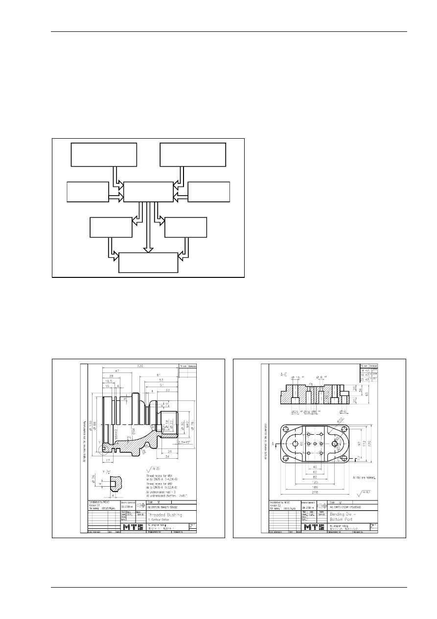
Procedure for manual NC programming
The procedure for manual programming can be divided into four steps:
1. analysis of workshop drawings
2. definition of work plans
3. choice of clamping devices and necessary tools (set-up sheet)
4. generating the NC program (program sheet)
Various documents must be analyzed and plans for production execution must be created. (see fig. 10).
s tu d y
w o rk s h o p d ra w in g
s tu d y
w o rk o rd e r
p ro g ra m m e r
cla m p in g
d e v ic e s
to o ls
w o rk p la n
se t-u p fo rm
p ro g ra m s h e e t
figure 10
Procedure for manual programming
Analysis of workshop drawings
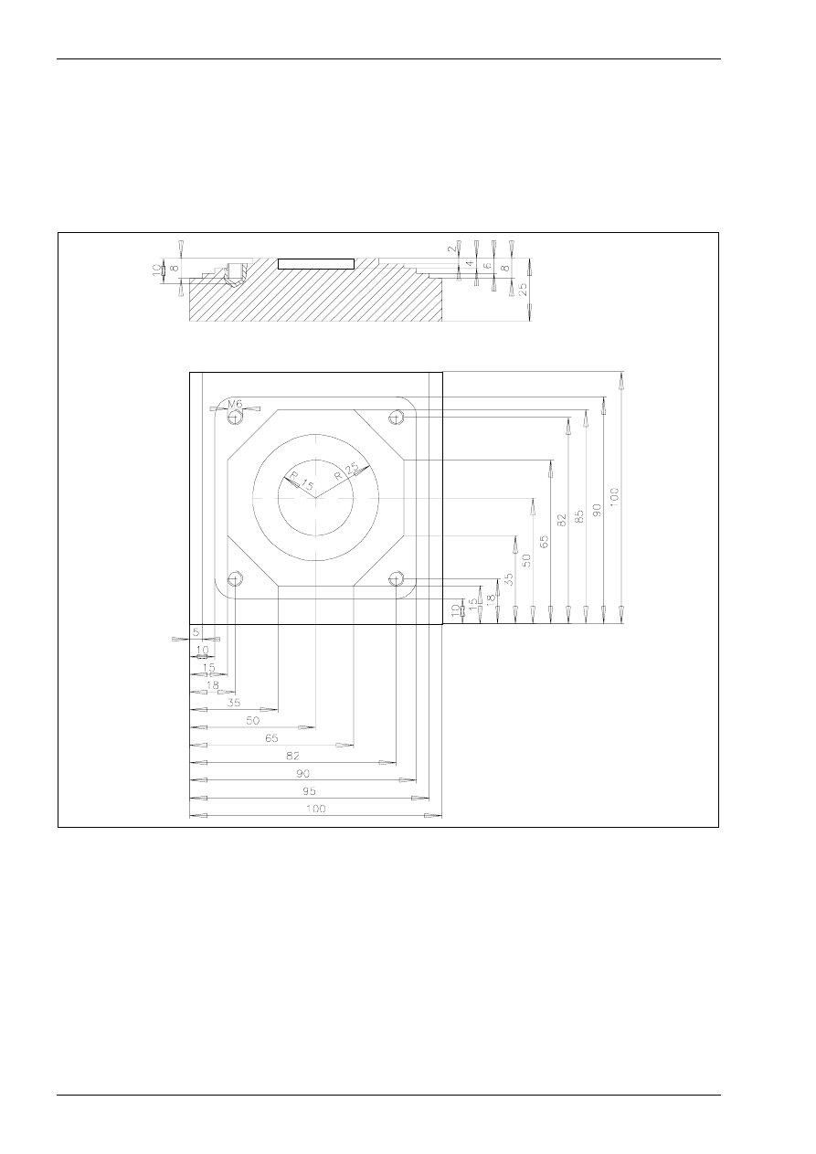
The workshop drawing (see fig. 11) contains the geometric and technical information for the finished part.
The dimensions, the surface specifications as well as information on the machining procedure to be used
(e.g. cutting, threading, hardening) are taken from the drawing. Information on the work to be executed as
well as on the number of work parts and the deadlines is specified in the work order.
figure 11
Workshop drawing turning
figure 12
Workshop drawing milling
Introduction into NC programming
© MTS GmbH 1997
170
Manual NC programming Turning
CNC exercise
Instructed generation of NC-programs for CNC-turning operations
Task:
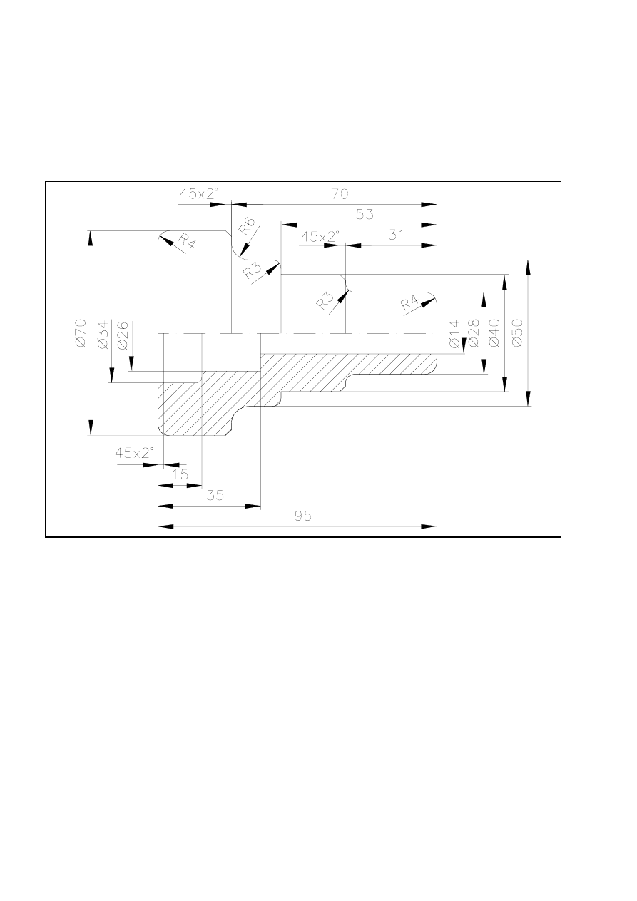
An NC-program is to be generated for manufacturing the following part.
figure 17
Follow the subsequent steps for generating the NC-program:
1. definition of the work plan
2. choice of clamping devices and necessary tools
3. generating the NC program
4. simulating the NC program
Introduction into NC programming
© MTS GmbH 1997
171
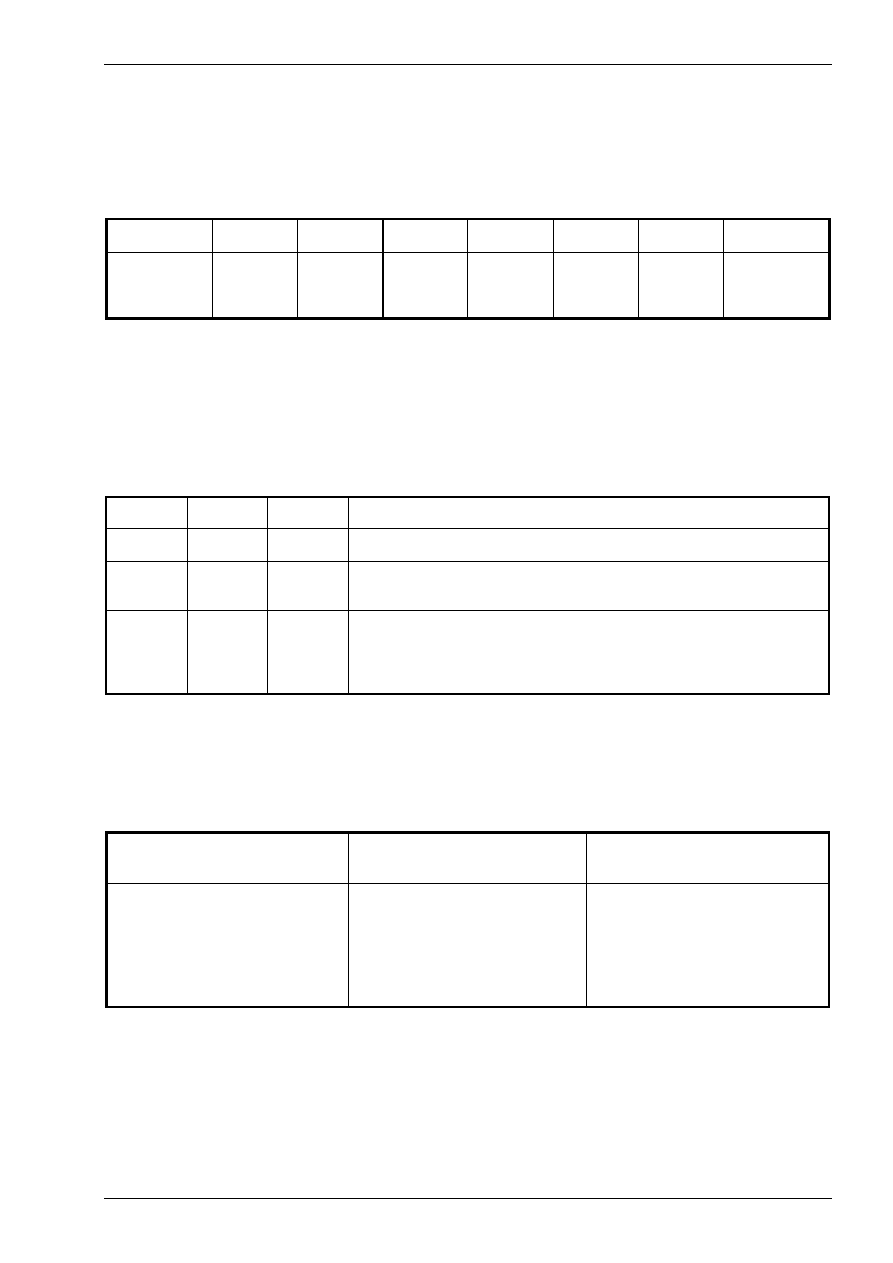
Definition of the work plan
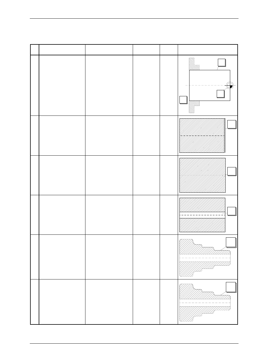
Work plan for machining the first side:
Machining Sequence
Tool
Turret Posi-
tion
Cutting
Values
Outline
1
2
3
check blank
dimensions
clamp work part
1.side
define work part zero
point
1
2
3
4 Face Turning
Left Corner Tool
CL-SCLCL-2020/R/1208
T04
G96
F0.15
S140
4
5 Centering
Center Drill
CD-03.15/050/R/HSS
T09
G97
F0.16
S1800
5
6 Drilling
Twist Drill Ø 14mm
DR-18.00/130/R/HSS
T07
G97
F0.22
S1000
6
7 Outside contour
roughing
Left Corner Tool
CL-SCLCL-2020/R/1208
T04
G96
F0.1
S140
7
8 Outside contour fin-
ishing
Left Corner Tool
CL-SVJCL-2020/R/1604
T02
G96
F0.1
S280
8
Introduction into NC programming
© MTS GmbH 1997
172
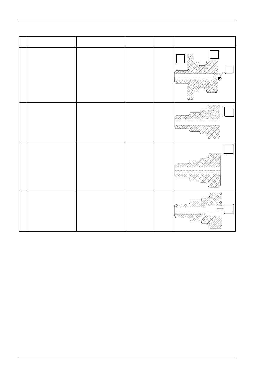
Work plan for machining the second side:
Machining Sequence
Tool
Turret Posi-
tion
Cutting
Values
Outline
1
2
3
check work part
clamp work part
2.side
define work part zero
point
1
2
3
4 Face Turning with
offset 0.2mm
Left Corner Tool
CL-SCLCL-2020/R/1208
T04
G96
F0.28
S140
4
5 Outside contour
roughing
Left Corner Tool
CL-SCLCL-2020/R/1208
T04
G96
F0.28
S140
5
6 Predrilling
Reversible Tip Drill
Ø 22mm
DI-22.00/051/R/HMT
T12
G97
F0.2
S850
6
Introduction into NC programming
© MTS GmbH 1997
173
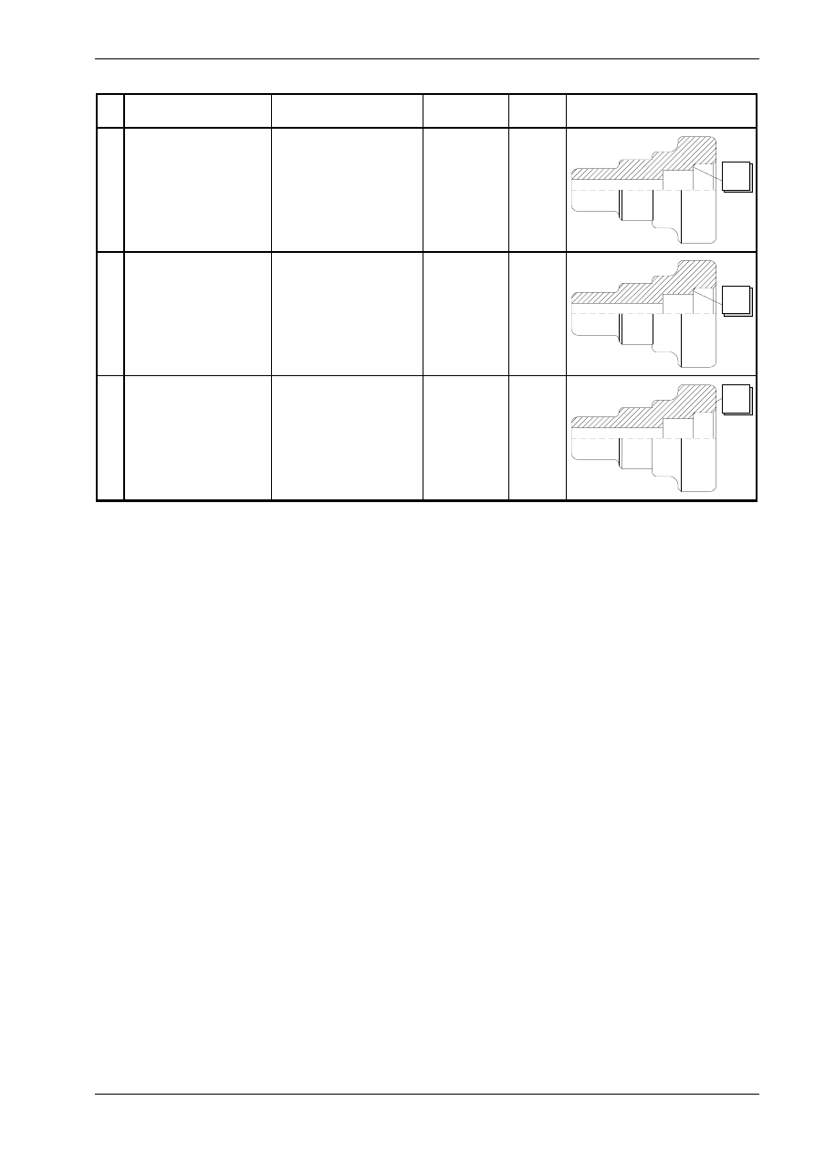
Machining Sequence
Tool
Turret Posi-
tion
Cutting
Values
Outline
7 Inside contour rough-
ing with offset
Inside Turning Tool
Post
BI-SDQCL-1616/R1104
T05
G96
F0.2
S120
7
8 Inside contour finish-
ing
Inside Turning Tool
Post
BI-SVQJCL-2020/R/1604
T10
G96
F0.1
S220
8
9 Outside contour fin-
ishing
Left Corner Tool
CL-SVJCL-2020/R/1604
T02
G96
F0.1
S280
9
Introduction into NC programming
© MTS GmbH 1997
189
Quality control by measuring work results
A work part can be measured after machining (automatic mode) or during machining after every operation
(single block) and can be compared with the values in the drawing.
Procedure:
Description
Entry
1. Call CNC turning in the main menu.
F1
(turning)
2. Select menu automatic mode.
F2
(automatic mode)
3. Call a present NC program,
par example GEWBU2.
Using the keyboard type in„GEWBU2“ and
confirm.
4. Select the simulation type „automatic mode“.
F1
(Automatic mode)
On the screen the simulation of the ma-
chining starts.
5. Select menu measurement.
F6
(Dimension 3D)
6. Select menu point dimension.
F6
(Point dimension)
7. Select the point for measurement.
F1
F2
(next point) or
(previous point)
For the selected point the data are shown
on the screen
8. Quit the menu measurement.
F8
F8
(Abort)
(Quit)
Introduction into NC programming
© MTS GmbH 1997
190
Manual NC programming Milling
CNC Exercise
Instructed generation of NC-programs for CNC-milling
Task:
An NC-program is to be generated for manufacturing the following part:
figure 26
Follow the subsequent steps for generating the NC-program:
1. definition of the work plan
2. choice of clamping devices and necessary tools
3. generating the NC program
4. simulating the NC program

Control test „Introduction into NC programming“
© MTS GmbH 1997
205
Control test „Introduction into NC programming“
1.
List the steps for manual programming.
2.
What is the difference between a work plan and a programming sheet?
3.
Explain the meaning of "switching information".
4.
Name and explain five commands for a CNC-machine.
5.
Explain the structure of an NC-program.
6.
Explain the structure of a program block.
7.
Explain the structure of a program word.
8.
Explain the address letters F, S, T, M, X, Y, Z.
9.
Explain the following program words for
a)
absolute programming (G90)
b)
incremental programming (G91)!
X 53, Z 184.005
10.
What do the address letters I, J, K express?
11.
Define the following functions with the corresponding program words
(G-command or M-command)
clockwise circular interpolation
activate coolant
activate spindle in clockwise rotation
12.
For which cases are constant cutting speeds required? Explain why.
13.
With which G-function is constant cutting speed programmed?
14.
Read and explain the following program block.
Illustrate the sequence of motions.
G01 G95 X100 Z-5 F0.25 S600 T0101
15.
Read and explain the following program block.
Illustrate the sequence of motions.
G02 G96 X30 Z-30 I30 K-15 F0.2 S180
16.
Read and explain the following program section!
N5
G90
G96
T0101
S100
M3
M8
N10
G0
X133
Z2
N20
G1
Z-395
F0.3
N30
G0
X135
Z2
N40
X123
N50
G1
Z-269.8
N60
G2
X133
Z-274.8
I133
K-269.8
O70
N70
G0
Z2

CNC-Turning -
Excerpt
MTS TeachWare Student’s Book
MTS Mathematisch Technische Software-Entwicklung GmbH • Kaiserin-Augusta-Allee 101 • D-10553 Berlin
Phone: +49 / 30 / 349 960 0 • Fax: +49 / 30 / 347 960 25 • World Wide Web: http://www.mts-cnc.com • email: mts@mts-cnc.com
Chapter 1
8
MTS TeachWare • CNC-Turning • Student’s Book
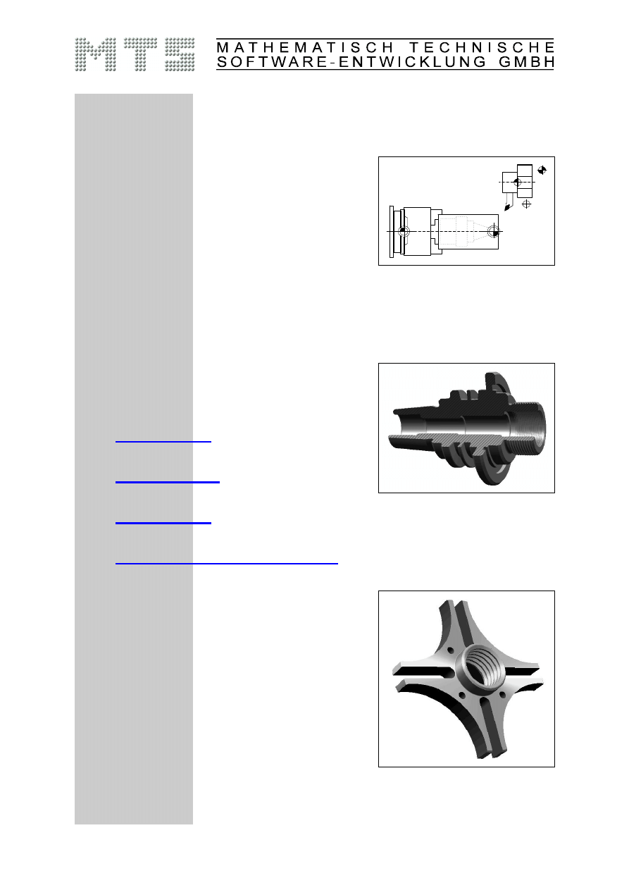
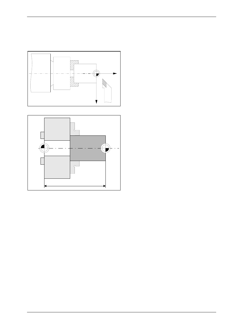
1.1.1 CNC turning machine
The CNC Turning Simulator simulates a 2-axis turning machine. In the CNC simulation all positioning and
feed movements appear to be made by the tool carrier, so the chuck and the work part have a fixed position
and the tool moves in both coordinates.
Figure 3
Schematic of the machine configuration
The work part can be clamped by using:·
•
lathe chuck with step jaws,
•
collet chuck,
•
collet,
•
face driver·or
•
lathe centres.
Figure 4
CNC Turning,workpart and clamping
definition;"Clamping Fixture Selection" menu.
Figure 5
CNC Turning, clamping between centers.
The magazine holds may up to 99 tool positions (pockets) in which the tools are inserted from the tool
manager. In the actual configuration we use 12 tools.
Introduction into working with the CNC simulator turning
© MTS GmbH • Berlin
9
The following tool types are available in the Tool Manager:
Right handed corner cutter
Left handed corner cutter
Copying tool
Circular tip turning tool
Boring tool (postaxial)
Boring tool (preaxial)
External recessing tool
Inside recessing tool (postaxial)
Inside recessing tool (preaxial)
Axial recessing tool
Right handed threading tool
Left handed threading tool
Available tools in the CNC-Simulator
Introduction into working with the CNC simulator turning
© MTS GmbH • Berlin
19
1.3.4 Data management
The internal data management functions provide a convenient means for documenting and backing up all
work results. These functions include:
•
NC Program Manager;
•
Tool Manager;
•
Clamping Fixture Manager;
•
Saving created work parts;
•
Saving current editing progress;
•
Generating various set-up sheets and
•
Managing configuration files.
Example: The CNC Simulator has its own tool management function. The program provides almost all ISO
tool types and tools as standard options, and allows all common tools to be defined. Naturally, the tool
management includes options for editing the available tool files, i.e. modification of existing tools and deletion
of those no longer required.
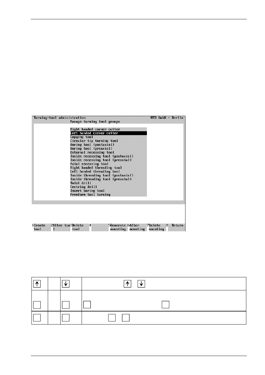
Figure 19
CNC Turning, Define/Delete Tools; Main Menu.
The screen layout of the Define/Delete Tools main menu is divided into two sections: the upper screen area
contains a listing of all available tool types; the field currently in use is highlighted in color. As usual, further
steps for specifying or editing tool data are indicated on the function keys at the bottom of the screen.
Select the desired step only by pressing the function keys rather than with the mouse.
or
Use the cursor keys
or
to select the tool type.
F1
or
F5
Create Tool/Tool Adapter: To generate a new tool of the current tool type, select
F1
; to define a new tool mounting, use
F5
.
F8
or
ESC
Return: Use
F8
or
ESC
to conclude the current operation
Chapter 1
20
MTS TeachWare • CNC-Turning • Student’s Book
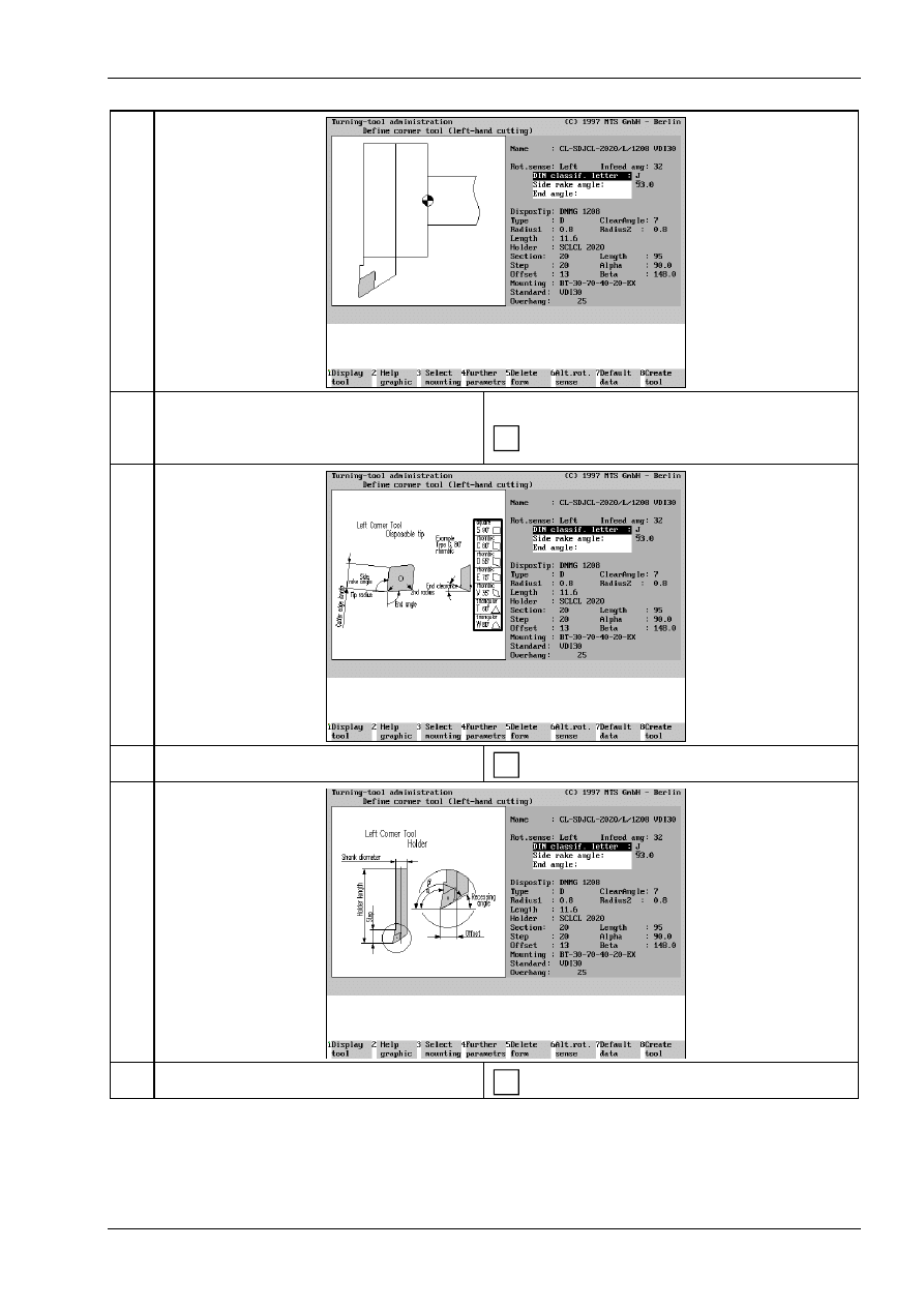
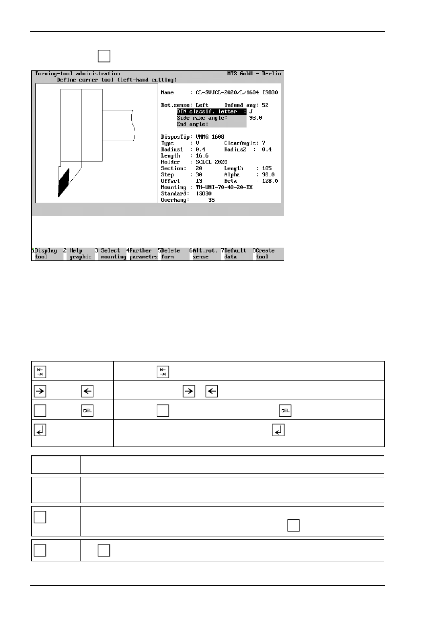
Having started in the main menu by selecting the tool type, and subsequently selecting the Create Tool
function by pressing
F1
, the Data Entry menu for defining the tool is loaded.
Figure 20
CNC Turning, Define/Delete Tools; defining a left-hand corner cutter.
The screen layout of the Data Entry menu is divided into three areas: the window on the left contains either a
help graphic or a graphic corresponding to the data of the tool being defined (including the tool adapter). The
input fields for the complete data record are located on the right.
You define a tool by manually entering the geometrical data, as well as the tool name and rotation direction.
The desired tool adapter data can be automatically copied by selecting the Select Tool Mounting function. To
save time, it is reasonable to define a new tool by first copying the data record of a similar tool, and then to
modify the data to meet your requirements.
Use the key
to move from input field to input field.
or
Use the cursor keys
or
to move the cursor within the input field.
INS
or
Use the key
INS
to insert a character, and the key
to delete one.
If you confirm the entry in the input field with the
key, the cursor moves
automatically to the next input field.
[Tool Name]
Enter the tool name or number in this input field.
[Parameter]
The entries required for a tool depend on the tool type. Use the help graphics to obtain
information on the parameters.
F8
Create tool: When the data entry for all tool and tool adapter parameters has been
completed, you save the tool under a certain name by pressing
F8
.
ESC
Use
ESC
to conclude the operation, and to return to the Define/Delete Tools main menu.
Introduction into working with the CNC simulator turning
© MTS GmbH • Berlin
21
1.4 Special functions of the software
The CNC Simulator incorporates some special functions which effectively support processing and NC
programming:
•
3D representation
•
Programming aids for ISO commands
•
Setting-up automatics, set-up sheet
•
Status management
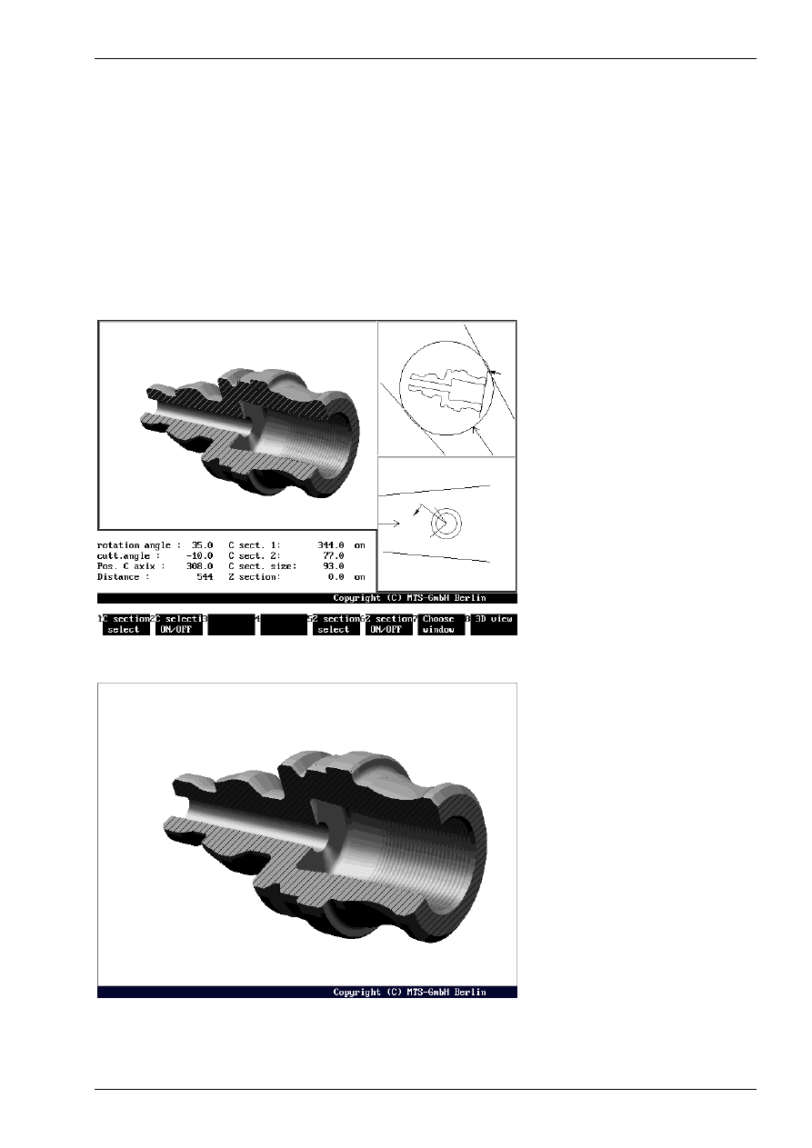
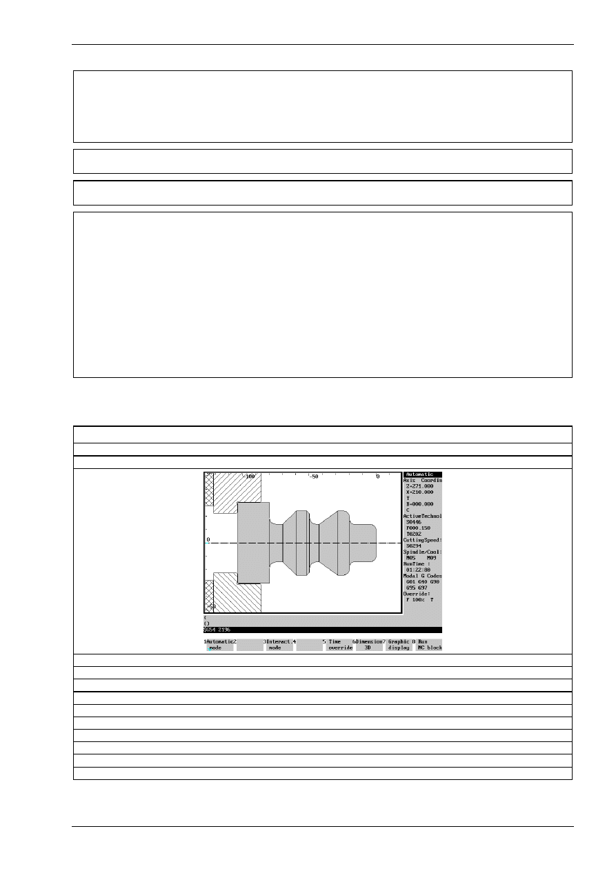
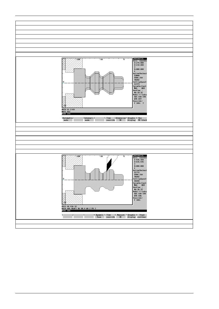
1.4.1 3D representation
A function supporting CNC training is given by the option to display, at any time, 3D Views of the work part,
seen from different viewing angles. The program features 3D displays in Turning Simulators. To display
machining inside the work part, any work part can be cut out.
Figure 21
CNC Turning, 3D View
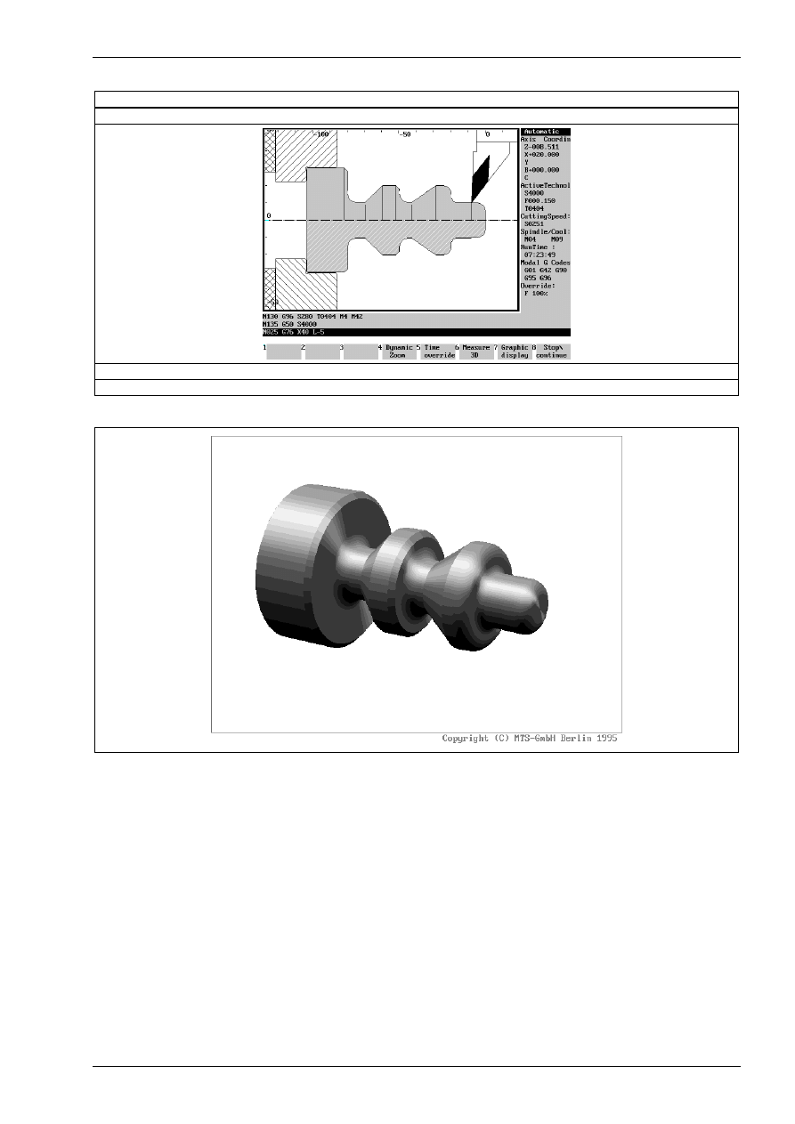
Figure 22
CNC Turning, 3D Display, full part with intersections
Introduction into working with the CNC simulator turning
© MTS GmbH • Berlin
23
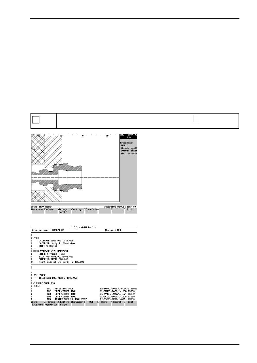
1.4.3 Setting-up automatics, set-up sheet
A Set-up Sheet contains all the information needed to set-up the machine by the operator. This sheet is used
by the MTS-Software for an automatic set-up of the simulated machine tool when starting an NC program.
This information includes:
•
blank/work part geometry
•
clamping fixture and method
•
tool in working position and magazine configuration
•
offset values of the tools used
A Set-up Sheet can be created for every current machine tool situation. It is prefixed to the NC program for
which the set-up sheet was created. During the NC program load in Automatic Mode or for interactive
programming the CNC Simulator is set-up automatically with the Setup Sheet Interpreter according to the
stored information, but the Set-up Sheet Interpreter must be active.
To have a machine tool status loaded automatically during the CNC Simulator start, you can specify the Set-
up Sheet describing that status in the configuration.
F4
Automatic Setup: this function is activated by pressing the function key
F4
from the main
menu. The CNC Simulator is then set-up automatically.
Figure 24
CNC Turning, Set-up Sheet menu
Figure 25
CNC Turning, example of a Set-up Sheet (excerpt)
Coordinate systems and Zero point shifts
© MTS GmbH • Berlin
29
2.3 Specifying the necessary location of the work part zero point
The work part zero point W is the origin of the work part-referenced coordinate system. Its location is
specified by the programmer according to practical criteria. The ideal location of the work part zero point
allows the programmer to take the dimensions directly from the drawing.
W
+ X
+ Z
For practical reasons the work part zero point W is
selected in turning in the right-hand plane surface
and in the rotation axis.
The work part zero point is set with reference to the
machine zero point M or to the predefined work part
zero point by setting the system variables.
Work part zero point
w
M
z
w
Using the operation functions described below the
distance in the Z-direction between the machine
zero point M and the work part zero point W is
specified.
This value zw, also called the zero point shift, is
then entered into the CNC control.
Procedure
Starting situation: All machining tools have been measured and are available on the turret head.
The clamping device is prepared and the work part has been correctly clamped.
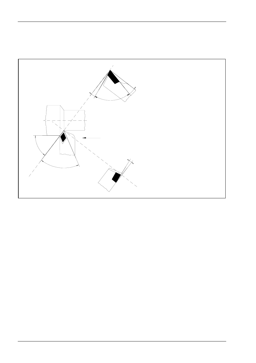
1. Switch on the spindle (counterclockwise rotation).
2. Change the tool to set the work part zero point, i.e. rotate the turret head to the corresponding position, for
instance T02.
Note:
The rotation area of the turret has to be checked first to avoid collision during rotation.
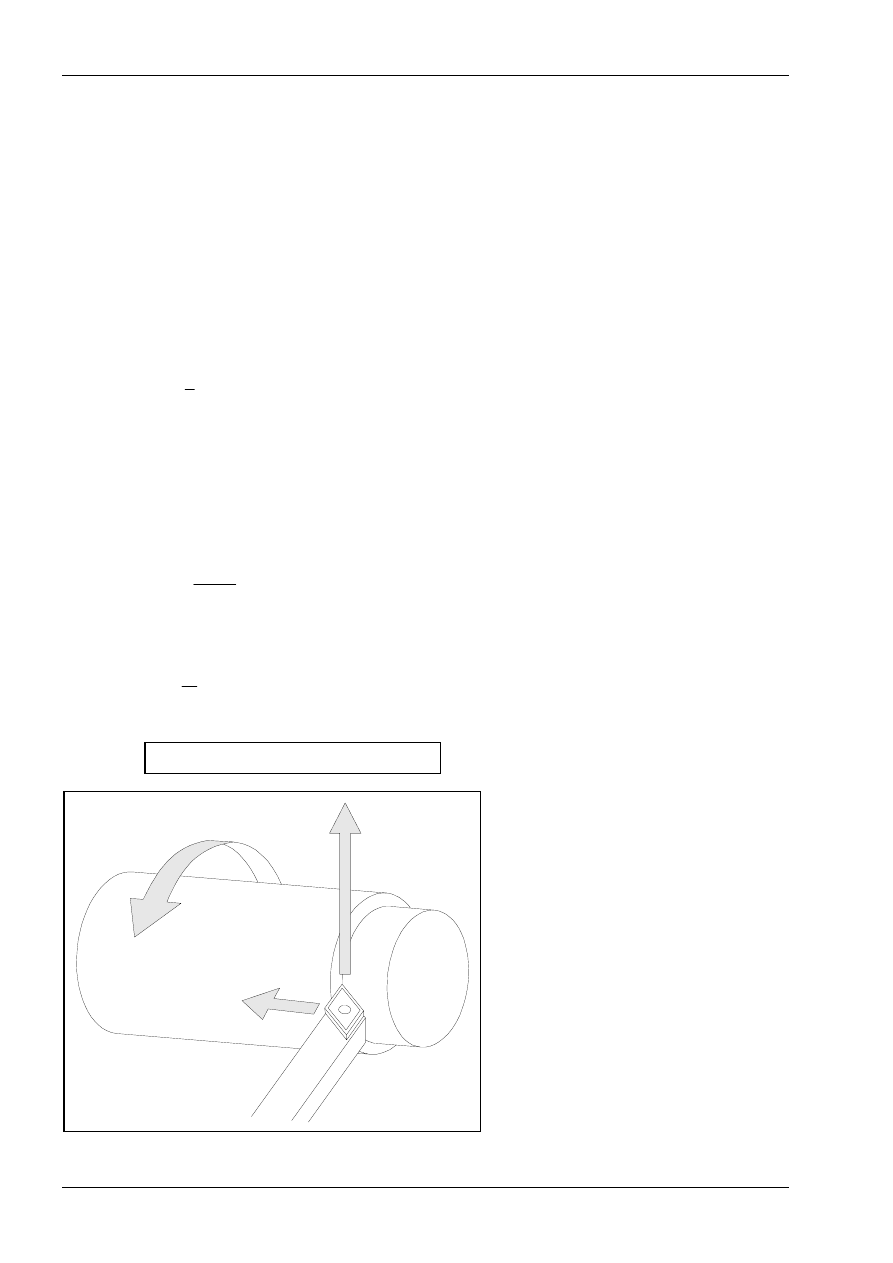
3. Touch the front plane area of the work part:
move carefully with the tool using the hand wheel
or using the corresponding arrow keys of the keyboard of the CNC control
until the cutting edge reaches a marking on the work part.
4. Enter the desired plane area allowance (e.g. 0.5 mm) on the CNC control.
Actuate with the zero key.
(The dimensions are used to face the front surface in z=0)
5. The CNC control then stores the value of the zero point shift zw.
The work part zero point W is clearly specified since the X coordinate zero is located on the rotation axis.
6. Because of eventual allowance the front side needs to be faced. This needs to be considered when
programming the NC program.
Chapter 3
50
MTS TeachWare • CNC-Turning • Student’s Book
3.3 Tool Offset Compensation
Using the tool offset compensation values it is easy to program a work part without consideration of the
actually applicable tool lengths or overhangs. The available work part drawing data can be directly used for
programming. The tool data, lengths as well as overhangs of the turning machines are automatically
considered by the CNC control.
B
L
B
Q
L
B
tool setup point
L
length = distance of the cutting tip to the tool
set-in point in Z
Q
overhang = distance of the cutting tip to the
tool setup point in X
Tool offset compensation values
In computing the tool movements the control system relates all programmed coordinates to the tool setup
point which is situated at the stop face of the tool mounting.
It follows that the distance between the theoretical cutting point of the tool nose and the tool setup point must
be determined for every tool, so that the actual tool path can be computed. Each of these differential values is
stored as a tool offset compensation value in a corresponding compensation value storage. When a
programmed tool change is to be executed in the course within NC program, the system reads in the
applicable compensation value storage, to account for the tool geometry in computing the tool path.
NC commands for programming „OKUMA 5020 L“
© MTS GmbH • Berlin
51
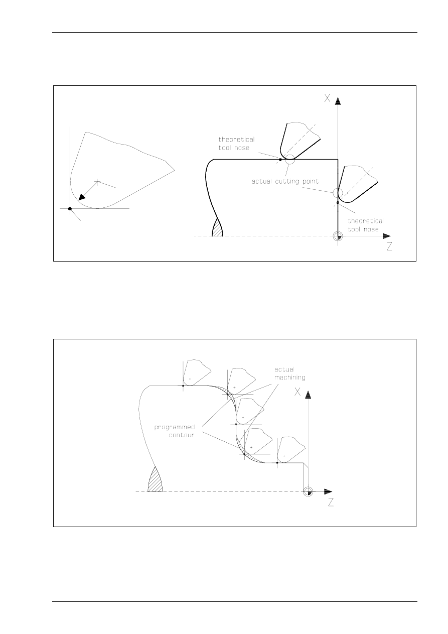
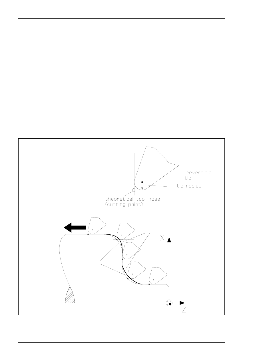
3.4 Tool Nose Compensation
The actual cutting point of the reversible tip changes during the course of machining, according to the tool
movement direction.
R
M
P
P
Theoretical tool nose
M
Tool nose Centre
In computing the tool motion the control system assumes the movement of the theoretical cutting point of the
tool nose along the programmed contour. Every time the tool executes a programmed movement which is not
parallel to either the X- or Z-axis, deviations from the desired contour and the corresponding dimensions are
unavoidable, due to the radius of the tool tip employed.
If tool nose compensation is not selected, the actual machining will deviate from the programmed contour on
the rising and falling segments of a contour, due to the radius of the tool tip.
Chapter 3
52
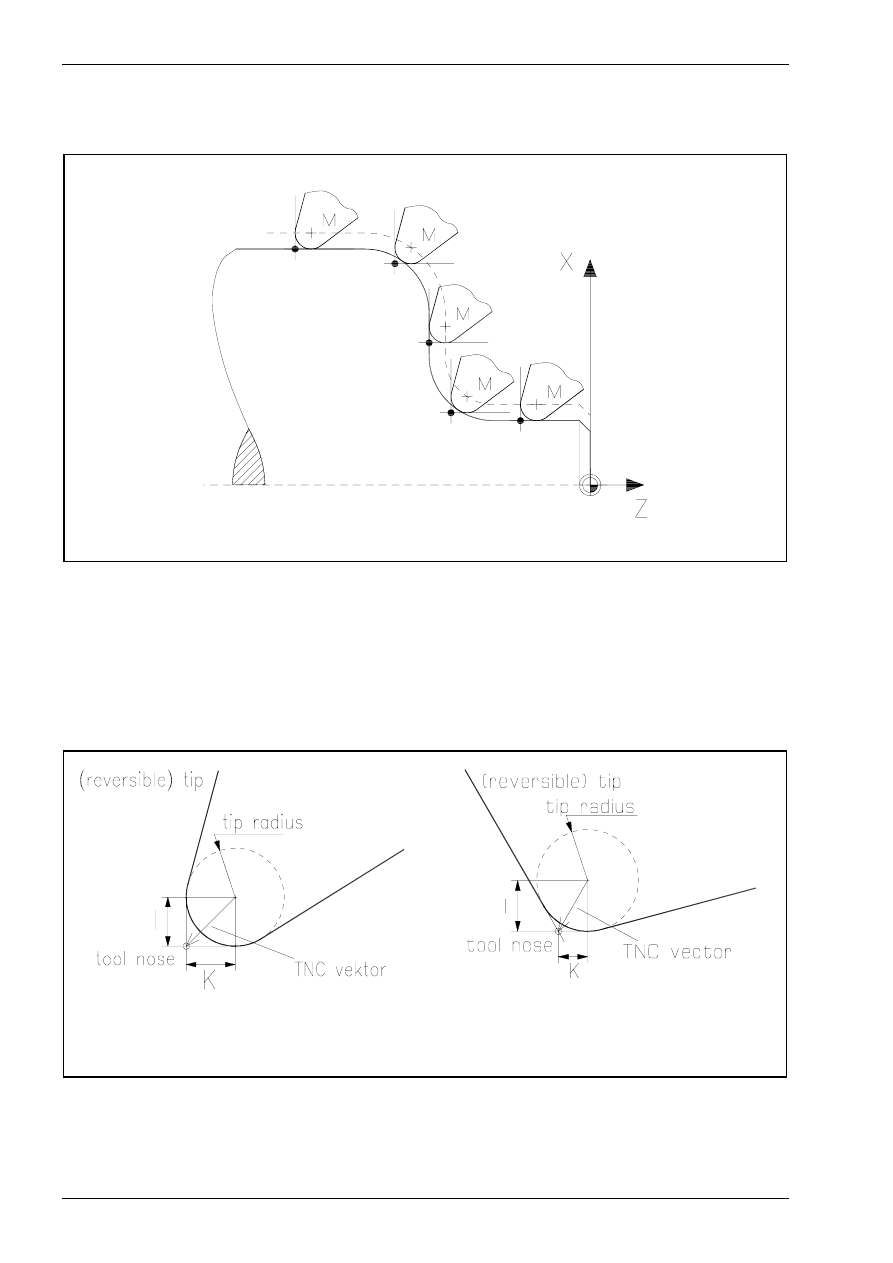
MTS TeachWare • CNC-Turning • Student’s Book
When tool nose compensation is activated, the control system computes the path of the centre of the tool
nose, equidistant to the contour, accounting for the radius.
- - -
Offset Path
M
Tool Nose Centre
If the tool nose compensation is selected the system computes the motion of the tool nose centre on an
offset path equidistant to the contour, i.e. the actual cutting point moves exactly along the programmed
contour of the workpiece.
With each tool the theoretical cutting point of the tool nose must be defined by the tool nose compensation
vector to make sure that the control system can compute the path of the actual cutting point in the execution
of a cycle. The tool nose compensation vector defines the theoretical position of the tool nose (in the
directions X and Z) relative to its centre.
Example:
Radius 0,4
I =-0,400
K=-0,400
Example: Radius 0,4
I =-0,400
K=-0,231
NC commands for programming „OKUMA 5020 L“
© MTS GmbH • Berlin
53
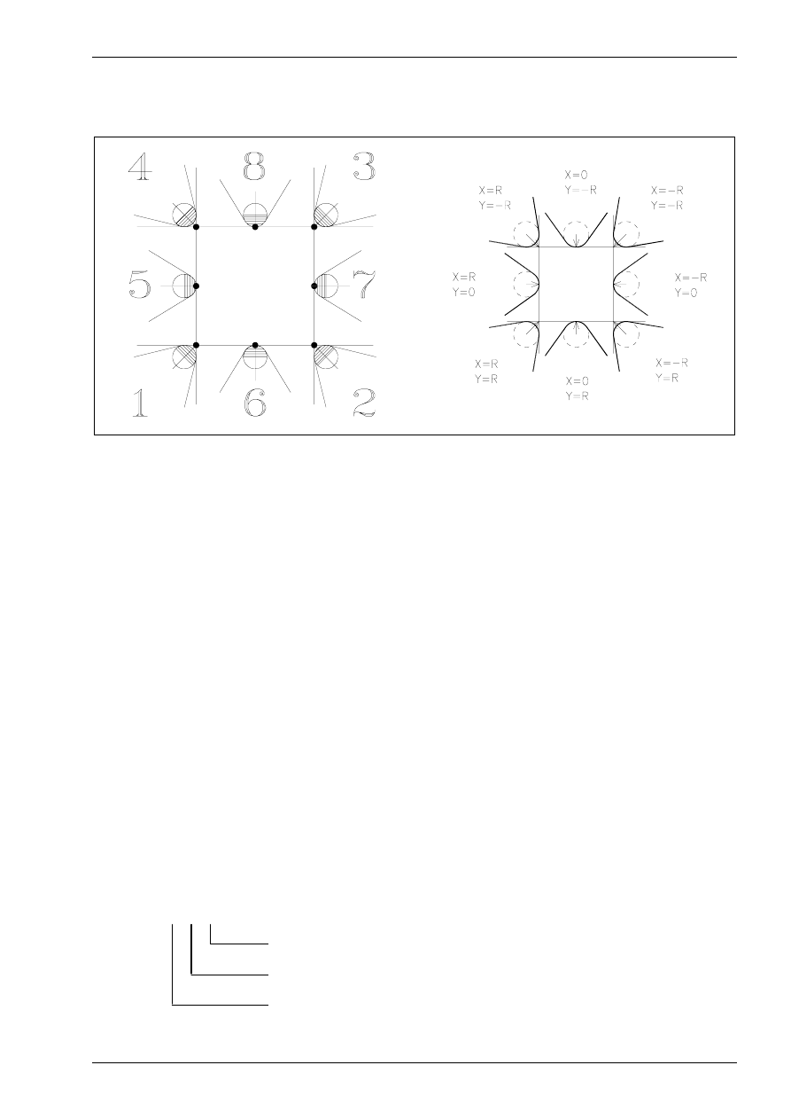
Alternatively the tool nose compensation vector can be determined by eight tooling quadrants. This is
common practice and applicable to standard cases.
tooling quadrants
tool nose compensation vectors
The tool management (see Simulator Operation Manual) predefines a TNC vector for every tool available in
the Simulator system.
3.4.1 Selection of Tool Compensation Values T
For programming with tool offset and tool nose compensation it is necessary to select the tool compensation
values of the actual tool by using the T command.
Command:
T
Tool selection command
Function:
Select the tool on the specified turret position with or without the tool nose
compensation.
NC-Block:
... T00 00 00...
Depending on the quantity of the subsequent digits the tool nose compensation is activated or not.
4 digit command
T00 00
without the tool nose compensation
6 digit command
T00 00 00
with the tool nose compensation
The digits describe the number of the tool and the number of the compensation storage.
T 00 00 00
tool offset number
tool number
tool nose compensation number
Chapter 3
56
MTS TeachWare • CNC-Turning • Student’s Book
3.4.4 Tool Nose Compensation Right G42
Command:
G42
Compensation to the right of the contour (in the cutting direction)
Function:
When the tool nose compensation is operative, only the work part contour points
are programmed and the control system must be informed whether the tool shall
move left or right of the programmed contour. The choiceof left or right applies to
the direction in which the tool travels along the contour
NC-Block:
G42 G01 [X...] [Z...] [F...]
Optional Addresses:
X
X-Coordinate of the Target Point
Z
Z-Coordinate of the Target Point
F
Feedrate
Note:
The command of the NC-block specifying G42 should be G00 or G01. When G42 is
specified by the commands G02 or G03 an alarm message is displayed.
For using the tool nose compensation the actual tool must be selected with the
6 digit Tool command
Programming Example:
N25 T030303
...
N100 G42
N105 (contour description)
...
N170 G40
m a ch in in g
d ire ctio n
p a th o f th e
th e o re tica l
to o l n o se
p ro g ra m m e d
co n to u r
Chapter 3
90
MTS TeachWare • CNC-Turning • Student’s Book
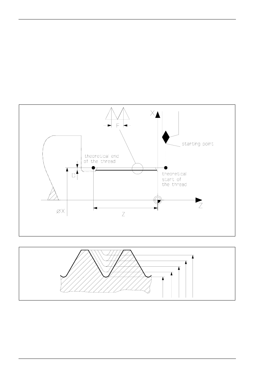
3.7 Thread Cutting G33
Command:
G33
Thread cutting
Function:
The G33 cycle serves to program thread cutting parallel to the Z-axis.
NC-Block:
G33 [X...] [Z...] [F...]
Optional Addresses:
X
diameter of each thread cutting cycle
Z
end point of thread in longitudinal direction
F
thread lead
X
nominal diameter of the thread
F thread lead
D
depth of the thread relative to the radius
Z Z-Coordinate of the theoretical end point of the thread
∅
X1
∅
X2
∅
X3
∅
X4
∅
X5
Note:
The successive infeeds must be programmed seperately by using the different
diameter X1, X2, X3 and so on.
Never change the spindle speed during the thread cutting cycle.
NC commands for programming „OKUMA 5020 L“
© MTS GmbH • Berlin
91
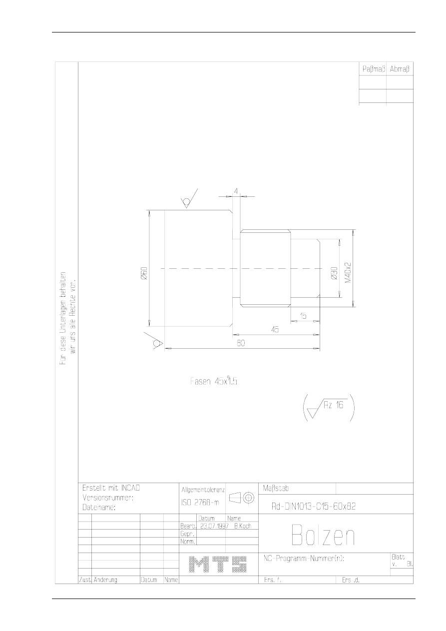
Example:
Create an NC-program for the following bolt with a thread.

NC commands for programming „OKUMA 5020 L“
© MTS GmbH • Berlin
93
N120
G0 X500 Z500 M9
N125
G96 S280 T020202 M3 M42 M63
N130
G50 S4000
N135
G87 NLAP1 U0 W0
N140
G0 X500 Z500 M9
N145
G96 S100 T080808 M3 M42 M63
N150
G50 S1500
N155
G0 X70 Z-45. M8
N160
G73 X30 Z-41. I4 K2.5 E0.5 D4 F0.12 T11
N165
G0 X62
N170
X500 Z500 M9 M5
N175
T101010 M3 M42 M63 G97 S1000
N180
G0 X50 Z5
N185
G33 X38.5 Z-42 L1 F2
N190
X38
N195
X37.8
N200
X37.7
N205
X37.6
N210
X37.55
N215
X37.52
N220
X37.5
N225
G0 X500 Z500 M5 M9
N230
M2
Finished part:
Subprogram technology
© MTS GmbH • Berlin
125
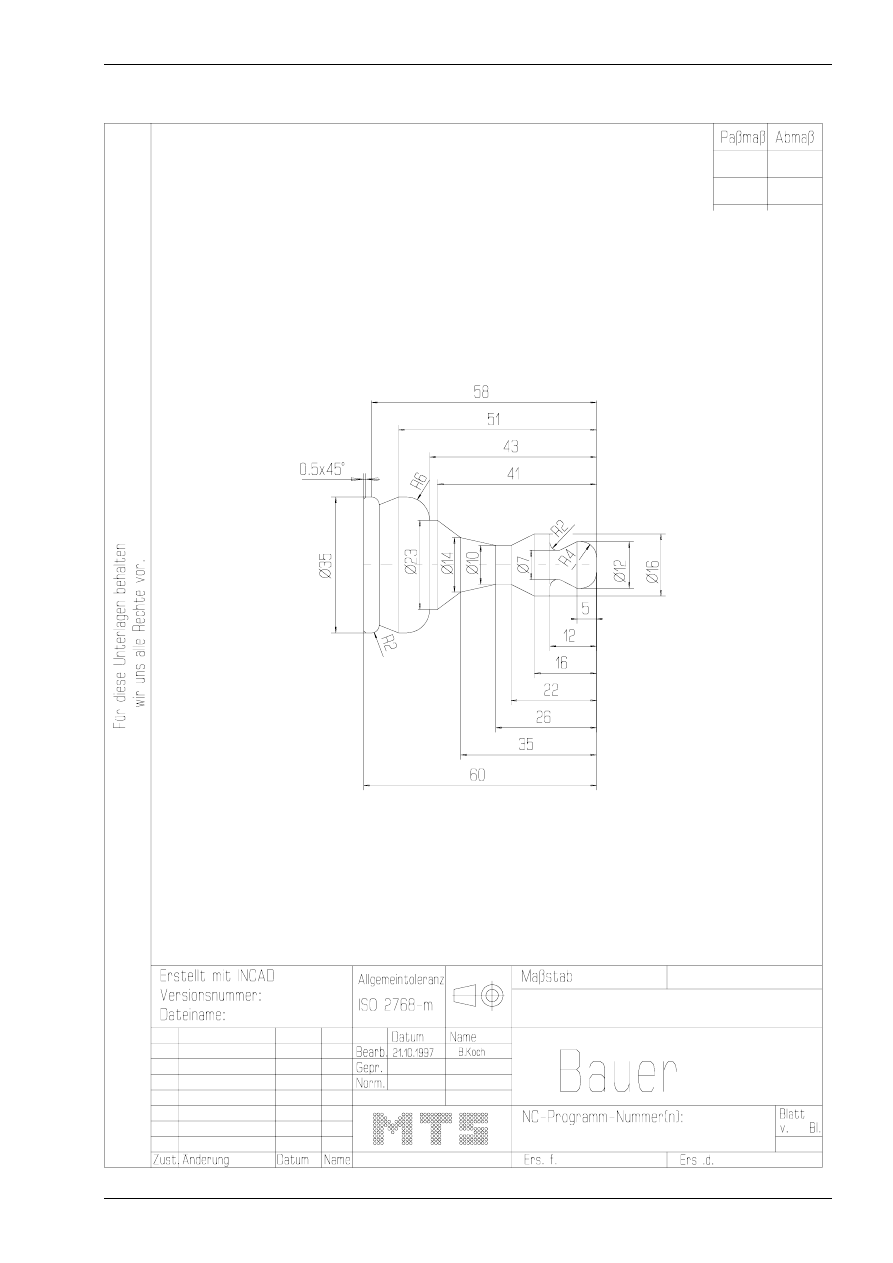
Example for using subprograms:
NC-program for the following chess figure with a subprogram by using absolute input values.
Chapter 5
128
MTS TeachWare • CNC-Turning • Student’s Book
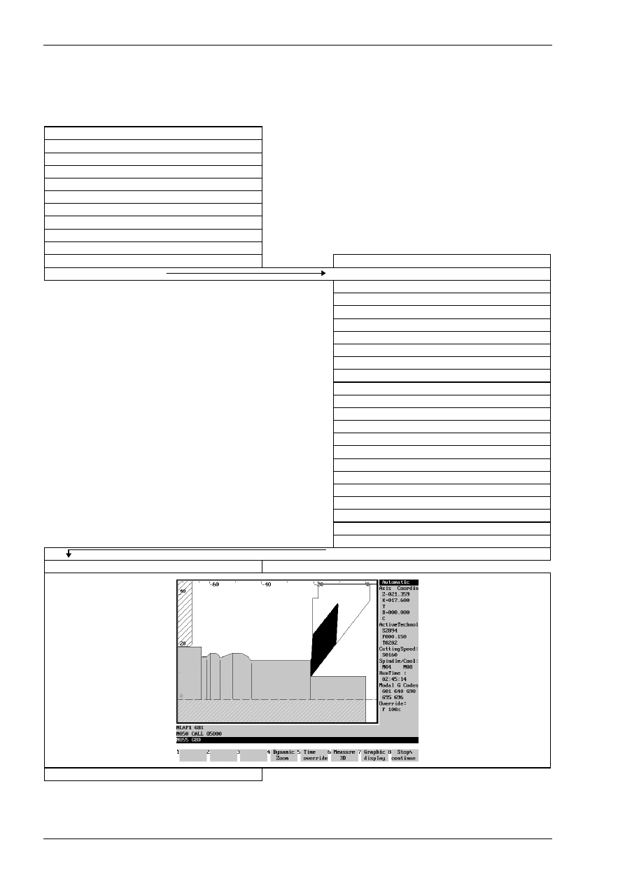
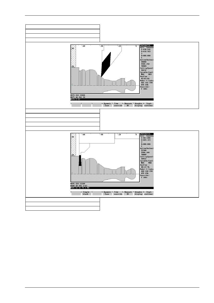
Programming Example
Subsequently, the program sequence with the subprogram call is shown.
main program baucall
$G54 Z177
O10022
N010
G0 X500 Z500 T020202 M3 M42 M63
N015
G96 S160
N020
G50 S3000
N025
G0 X42 Z0
N030
G1 X-1 F0.15 M8
N035
G0 X42 Z4
N040
G85 NLAP1 D6 U0.4 F0.25
NLAP1 G81
subprogram O5000.mm
N050
CALL O5000
N010
G0 G42 X0 Z2
N015
G1 X0 Z0
N020
G76 X12 L-4
N025
G1 Z-5
N030
X7 Z-10
N035
G2 X11 Z-12 L2
N040
G1 X16
N045
Z-16
N050
X10 Z-22
N055
Z-26
N060
X14 Z-35
N065
X23 Z-41
N070
Z-43
N075
G3 X35 Z-49 L6
N080
G1 Z-51
N085
X31 Z-56
N090
G3 X35 Z-58 L2
N095
G1 Z-59.5
N100
X32 Z-61
N105
Z-63
N110
X42
N115
G40
N120
RTS
N055
G80
N060
G0 X500 Z500 M9
Subprogram technology
© MTS GmbH • Berlin
129
N065
G96 S280 T040404 M3 M42 M63
N070
G50 S4000
N075
G0 X42 Z4
N080
G87 NLAP1 U0 W0
N085
G0 X500 Z500 M9
N090
G96 S100 T080808 M3 M42 M63
N095
G50 S1500
N100
G0 X42 Z-63
N105
G1 X2 F0.1 M8
N110
G0 X50
N115
X500 Z500 M9
N120
M30
Subprogram technology
© MTS GmbH • Berlin
149
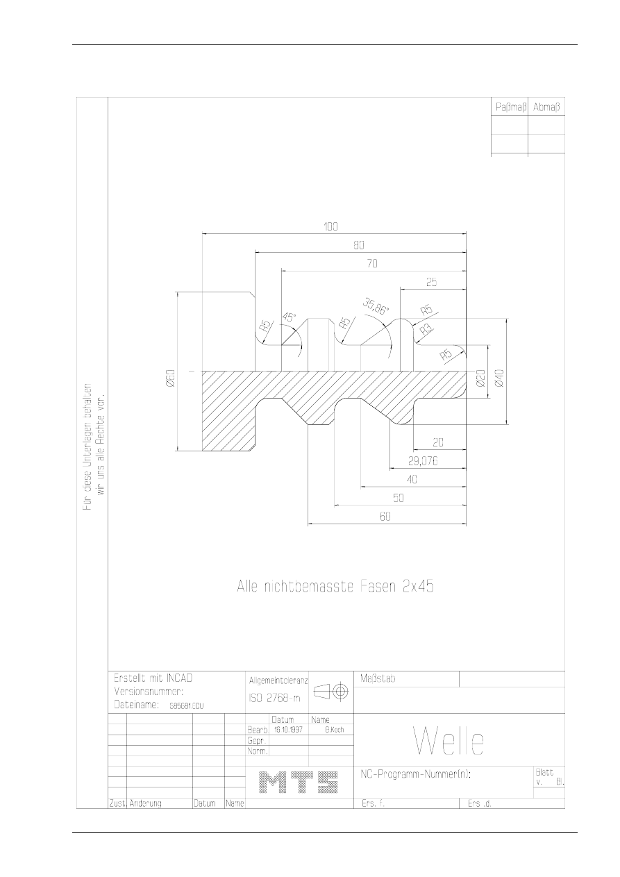
Example:
Create an NC-program for the following figure with the G86 longitudinal LAP-function by using the pre-
fabricated blank.
Subprogram technology
© MTS GmbH • Berlin
151
MAIN SPINDLE WITH WORKPART
CHUCK KITAGAWA B-208
STEP JAW WM-KIT_01.002
TYPE OF CHUCK EXTERNAL CHUCK OUTSIDE STEP JAW
CHUCKING DEPTH E18.000
RIGHT SIDE OF THE PART: Z+196.000
TAILSTOCK
TAILSTOCK POSITION Z+1100.000
CURRENT TOOL
T02
TOOLS
T01
LEFT CORNER TOOL
CL-SVJCR-2020/R/1604 ISO30
T02
LEFT CORNER TOOL
CL-SVJCR-2020/R/1604 ISO30
T03
FRONT GROOVING TOOL
RA-MBS-E5N-2.5/16/040-050/R ISO30
T04
LEFT CORNER TOOL
CL-SVJCR-2020/R/1604 ISO30
T05
INSIDE TURNING TOOL POST
BI-SDQCL-1212/L/0704 ISO30
T06
INTERN. THREADING TOOL POSTAX TI-ITTR-2016/R/60/1.50 ISO30
T07
TWIST DRILL
DR-14.00/108/R/HSS ISO30
T08
RECESSING TOOL
ER-SGTFR-2012/R/03.0-0 ISO30
T09
CENTER DRILL
CD-04.00/056/R/HSS ISO30
T10
LEFT CORNER TOOL
CL-MVJCL-2020/L/1604 IS030
T11
INSIDE TURNING TOOL POST
BI-SDUCL-1212/L/0704 ISO30
T12
REVERSIBLE TIP DRL
DI-22.00/051/R/HMT ISO30
ACCURATE OFFSET
Solution:
NC-program
$G54 Z196
O10086
NLAP1 G81
N005
G42 G0 X6 Z2
N010
G1 X8 Z0
N015
G76 X20 L-5
N020
G76 Z-20 L3
N025
G76 X40 L-5
N030
G3 Z-29.076 K0 I-5
N035
G1 X20 A215.86
N040
G76 Z-50 L5
N045
G75 X40 L-2
Chapter 5
152
MTS TeachWare • CNC-Turning • Student’s Book
N050
G1 Z-60
N055
G1 X20 A225
N060
G76 Z-80 L5
N065
G75 X60 L-2
N070
G1 Z-83
N075
X62
N080
G40
N085
G80
N090
G0 X500 Z500 T020202 M3 M42 M63
N095
G96 S200
N100
G50 S3000
N105
G0 X62 Z0
N110
G1 X-1 F0.15 M8
N115
G0 X16 Z2
N120
G86 NLAP1 D6 U0.4 W0.2 F0.3
N125
G0 X500 Z500 M9
N130
G96 S280 T040404 M3 M42 M63
Subprogram technology
© MTS GmbH • Berlin
153
N135
G50 S4000
N140
G87 NLAP1 U0 W0
N145
G0 X500 Z500 M5 M9
N150
M2
Finished part:

CNC-Milling -
Excerpt
MTS TeachWare Student’s Book
MTS Mathematisch Technische Software-Entwicklung GmbH • Kaiserin-Augusta-Allee 101 • D-10553 Berlin
Phone: +49 / 30 / 349 960 0 • Fax: +49 / 30 / 347 960 25 • World Wide Web: http://www.mts-cnc.com • email: mts@mts-cnc.com
Chapter 1
8
MTS TeachWare • CNC-Milling • Student’s Book
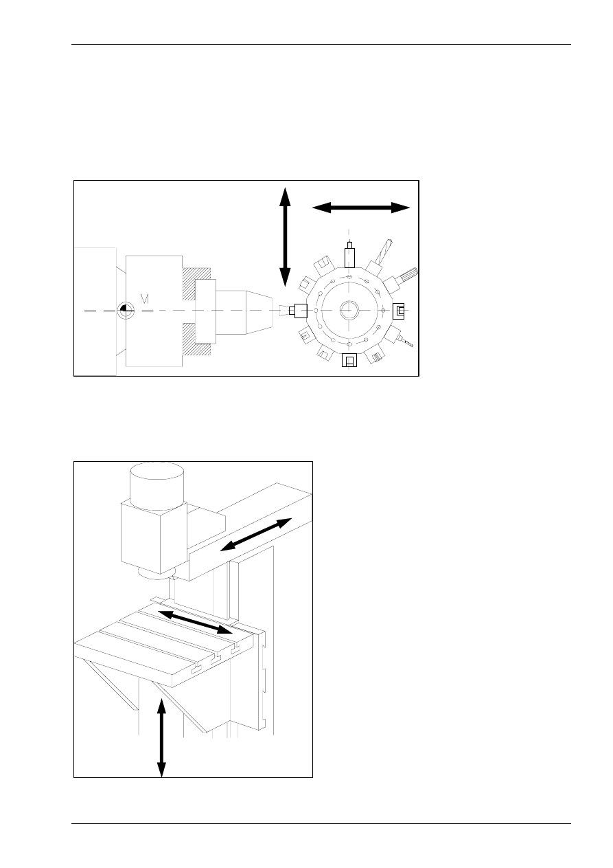
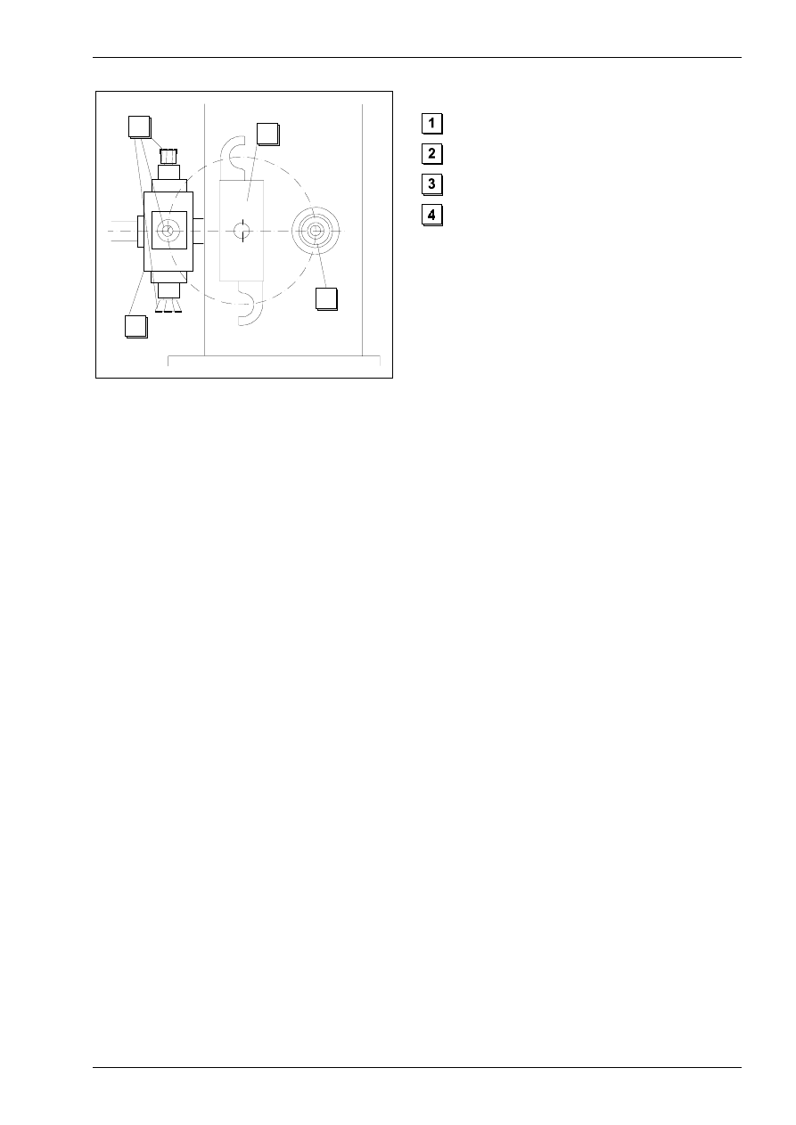
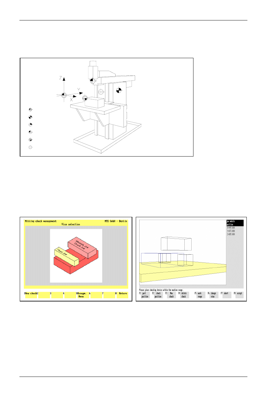
1.1.1 CNC milling machine
The CNC Milling Simulator simulates a 3-axis milling machine with vertical spindle position. In the CNC
simulation all positioning and feed movements appear to be made by the tool carrier, so the machine table
and the work part have a fixed position and the tool moves in all three coordinates.
M ac hin e zero
too l m oves in Y
table m oves in X an d Z
R efe re n ce p o in t
W o rkp ie ce Z e ro
To ol refere n ce p o in t
Too l ch an g e p o in t
Tu rre t re fe re nce p oin t
Figure 3
Schematic of the machine configuration
In the MAKINO CNC Milling machine the tool moves in Y- and Z-direction and the machine table moves in X-
direction.
The work part can be clamped by using:·
•
jaws,
•
magnetic plate·or
•
modular clamping.
Figure 4
jaws
Figure 5
modular clamping
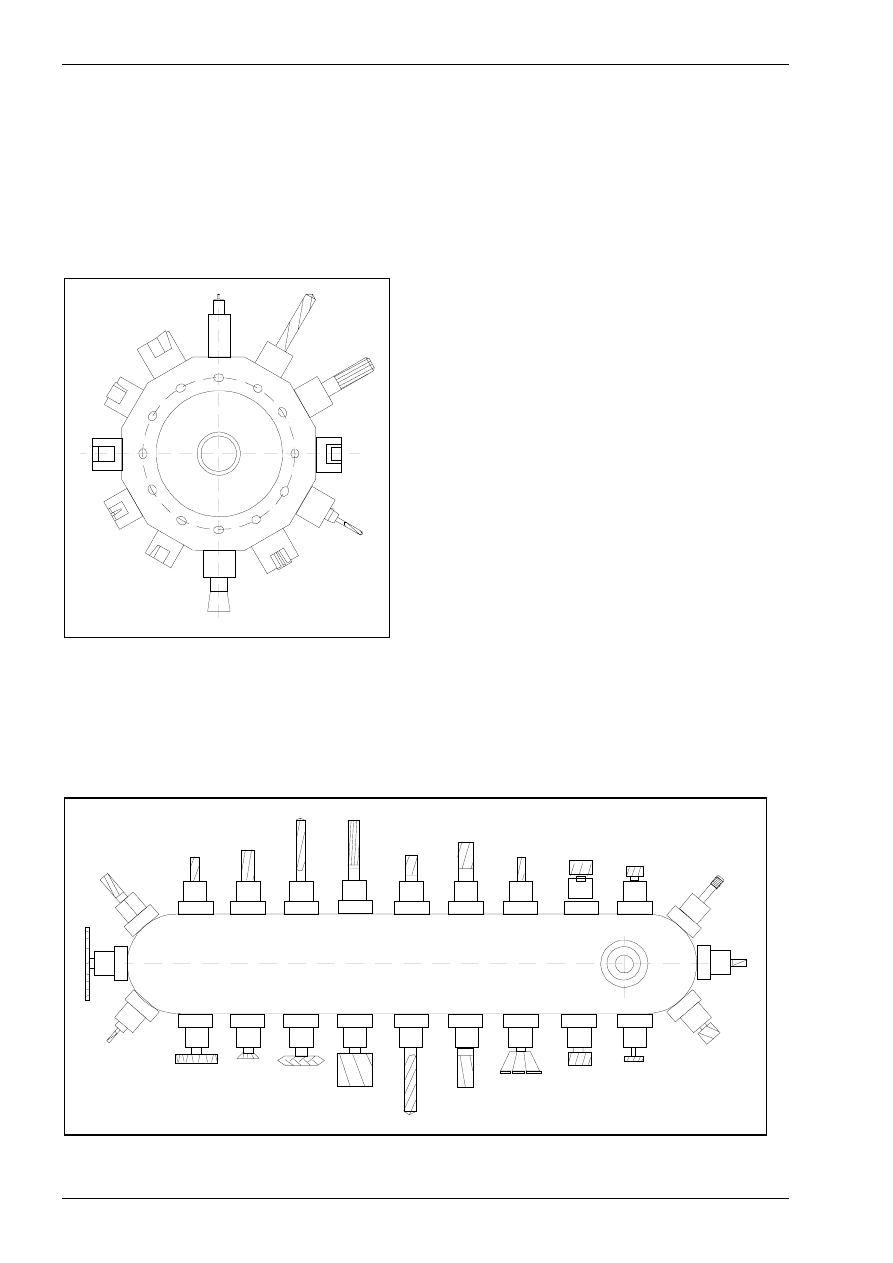
The magazine holds may up to 99 tool positions (pockets) in which the tools are inserted from the tool man-
ager. In the actual configuration we use 16 tools.
Introduction into working with the CNC simulator milling
© MTS GmbH • Berlin
9
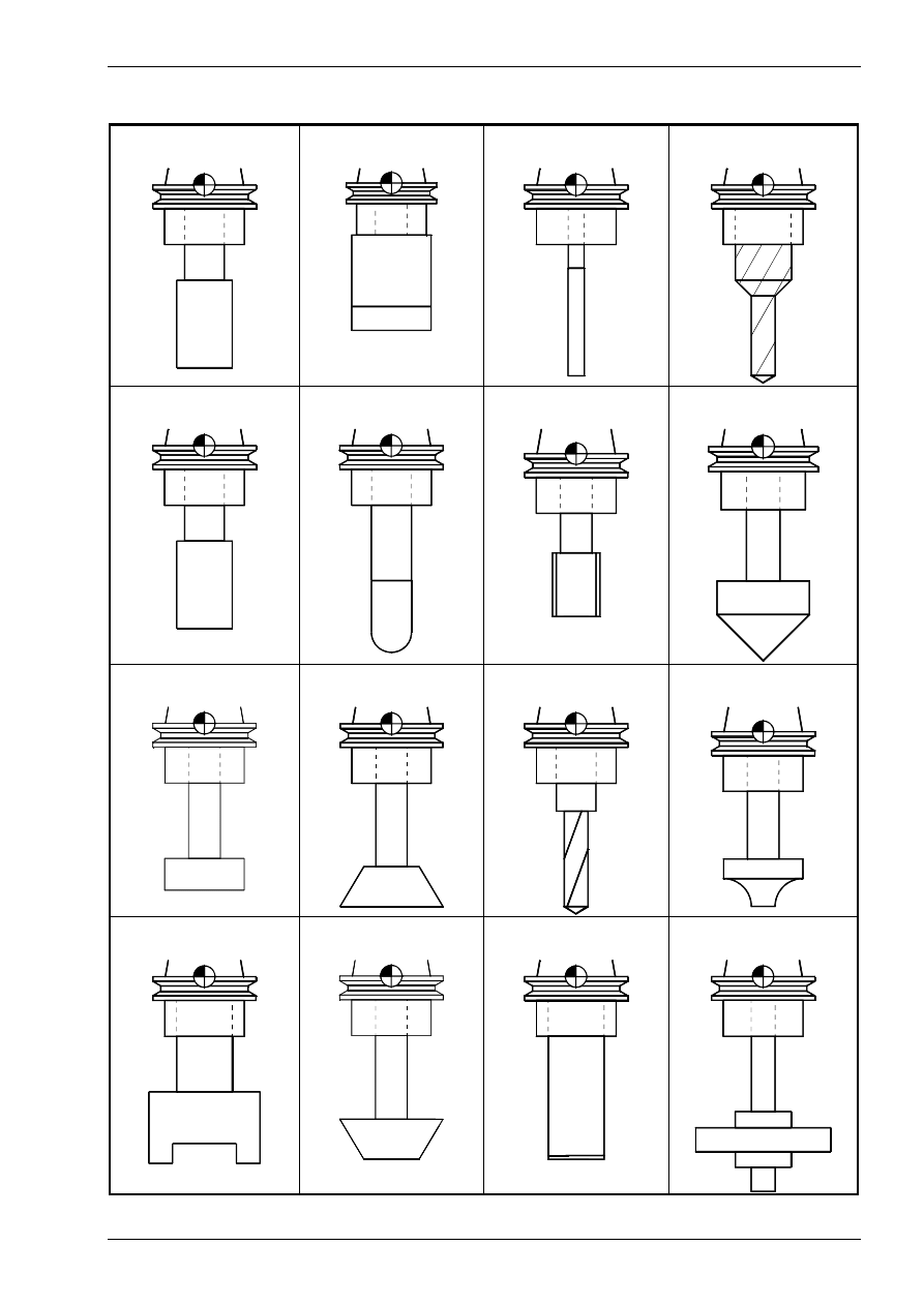
The following tool types are available in the Tool Manager:
End mills
Face milling cutters
Reamers
Step drills
Slot milling tools
Radius cutters
Taps
Core drills
T-slot cutters
Corner tool (Type A)
Drills
Concave type cutters
Shell end mills
Corner tool (Type B)
Insert tip drills
Side milling tools
Introduction into working with the CNC simulator milling
© MTS GmbH • Berlin
19
1.3.4 Data management
The internal data management functions provide a convenient means for documenting and backing up all
work results. These functions include:
•
NC Program Manager;
•
Tool Manager;
•
Clamping Fixture Manager;
•
Saving created work parts;
•
Saving current editing progress;
•
Generating various set-up sheets and
•
Managing configuration files.
Example: The CNC Simulator has its own tool management function. The program provides almost all ISO
tool types and tools as standard options, and allows all common tools to be defined. Naturally, the tool man-
agement includes options for editing the available tool files, i.e. modification of existing tools and deletion of
those no longer required.
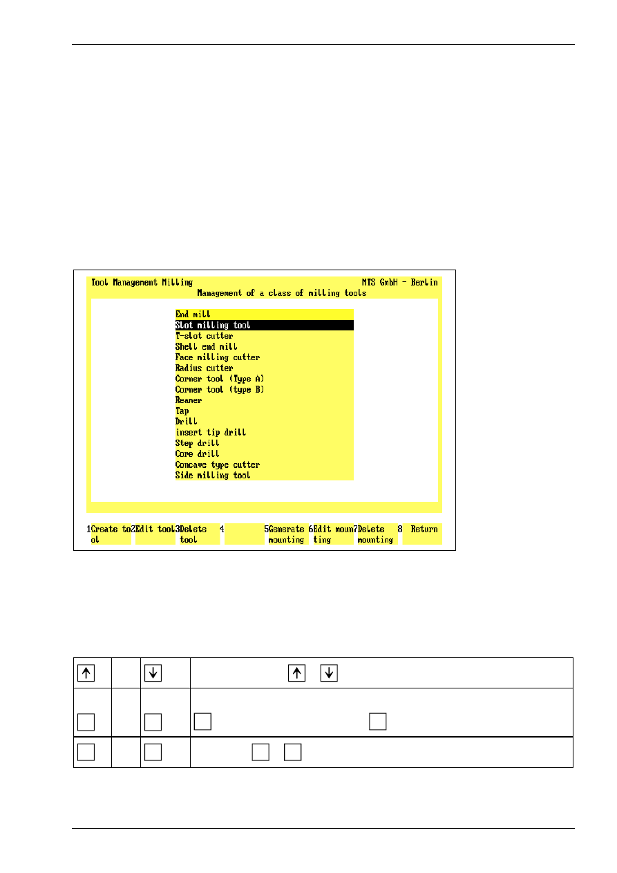
Figure 17
CNC Milling, Define/Delete Tools; Main Menu.
The screen layout of the Define/Delete Tools main menu is divided into two sections: the upper screen area
contains a listing of all available tool types; the field currently in use is highlighted in color. As usual, further
steps for specifying or editing tool data are indicated on the function keys at the bottom of the screen.
Select the desired step only by pressing the function keys rather than with the mouse.
or
Use the cursor keys
or
to select the tool type.
F1
or
F5
Create Tool/Tool Adapter: To generate a new tool of the current tool type, select
F1
; to define a new tool adapter, use
F5
.
F8
or
ESC
Return: Use
F8
or
ESC
to conclude the current operation
Chapter 1
20
MTS TeachWare • CNC-Milling • Student’s Book
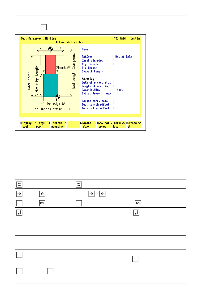
Having started in the main menu by selecting the tool type, and subsequently selecting the Create Tool func-
tion by pressing
F1
, the Data Entry menu for defining the tool is loaded.
Figure 18
CNC Milling, Define/Delete Tools; defining a slot cutter.
The screen layout of the Data Entry menu is divided into three areas: the window on the left contains either a
help graphic or a graphic corresponding to the data of the tool being defined (including the tool adapter). The
input fields for the complete data record are located on the right.
You define a tool by manually entering the geometrical data, as well as the tool name and rotation direction.
The desired tool adapter data can be automatically copied by selecting the Select Tool Adapter function. To
save time, it is reasonable to define a new tool by first copying the data record of a similar tool, and then to
modify the data to meet your requirements.
Use the key
to move from input field to input field.
or
Use the cursor keys
or
to move the cursor within the input field.
INS
or
Use the key
INS
to insert a character, and the key
to delete one.
If you confirm the entry in the input field with the
key, the cursor moves auto-
matically to the next input field.
[Tool Name]
[Tool Name]
Enter the tool name or number in this input field.
[Parameter]
The entries required for a tool depend on the tool type. Use the help graphics to obtain in-
formation on the parameters.
F8
Create tool: When the data entry for all tool and tool adapter parameters has been com-
pleted, you save the tool under a certain name by pressing
F8
.
ESC
Use
ESC
to conclude the operation, and to return to the Define/Delete Tools main menu.
Introduction into working with the CNC simulator milling
© MTS GmbH • Berlin
21
1.4 Special functions of the software
The CNC Simulator incorporates some special functions which effectively support processing and NC pro-
gramming:
•
3D representation
•
Programming aids for ISO commands
•
Setting-up automatics, set-up sheet
•
Status management
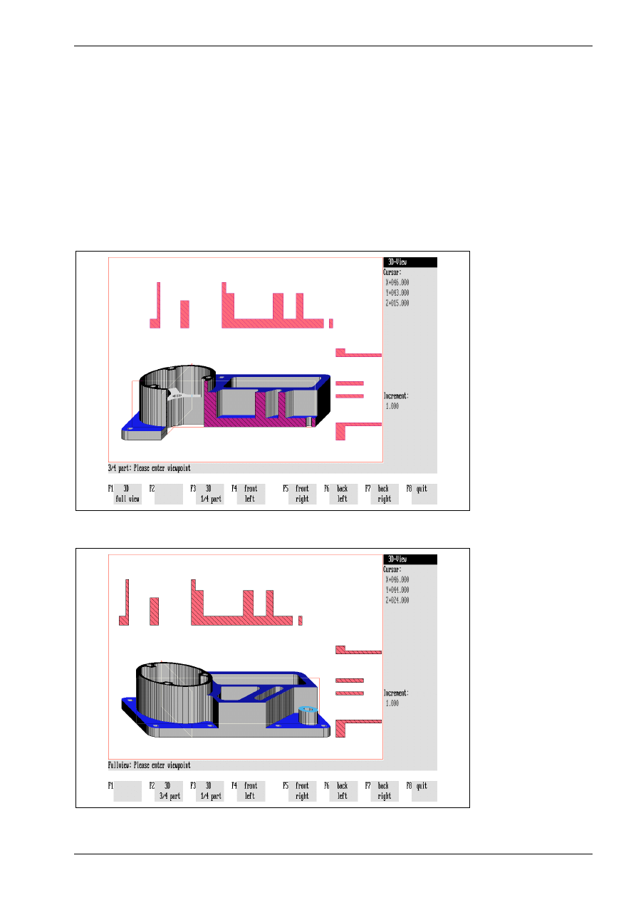
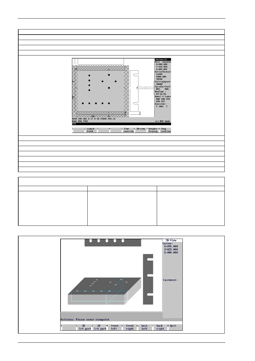
1.4.1 3D representation
A function supporting CNC training is given by the option to display, at any time, 3D Views of the work part,
seen from different viewing angles. The program features 3D displays in Milling Simulators. To display ma-
chining inside the work part, any work part quadrants can be cut out.
Figure 19
CNC Milling,3D View, three-quarter view with intersections
Figure 20
CNC Milling, 3D Display, full part with intersections
Chapter 2
30
MTS TeachWare • CNC-Milling • Student’s Book
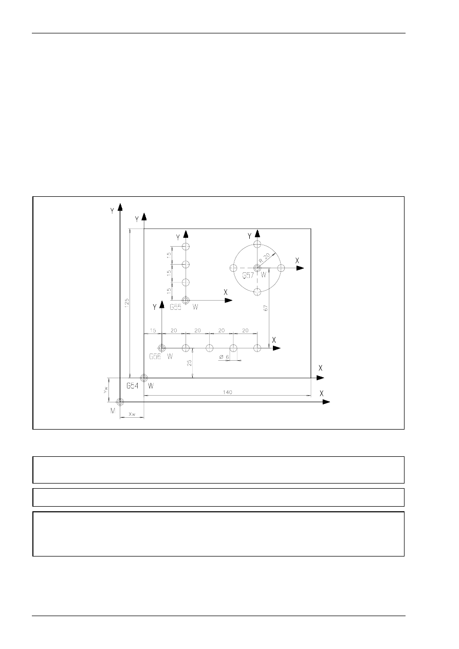
2.2.3 Setting the work part coordinate system with the commands G54 - G59
Six different work part coordinate systems can be used, for example, to program complex or repetitive con-
tours. The coordinates of the respective zero point may measured as the distance between the reference
point of the work part and the machine zero point. The value and the direction of this distance may be stored
into the NC control.
Each stored zero point will be activated with the corresponding command (G54 - G59) in the NC program.
Note:
Coordinate values of all zero points always relate to the machine zero point.
Exercise:
Create an NC-program for the following plate with respect to the newly defined work part zero points.
Use the following configuration:
CONFIGURATION
MACHINE MAKINO FX 650
CONTROL FANUC 16M FX650
BLANK DIMENSIONS
X+140.000 Y+125.000 Z+025.000
VISE
MAKFX 160
CHUCKED HEIGHT E+031.000
SHIFT V+000.000
ORIENTATION A0°
Chapter 2
32
MTS TeachWare • CNC-Milling • Student’s Book
N095
G57
N100
G0 X0 Y0 M8
N105
G91
N110
G98 G82 Z-17 R-38 P2000 F80 L0
N115
M98 P907
N120
G53
N125
G54
N130
G0 Z20 M5
N135
G91 G28 Z0 M9
N140
G91 G28 X0 Y0
N145
G90 G49 G80 G40
N150
M30
Subprograms
0905
0906
0907
N10 G91 G99 X0 Y0
N15 X20
N20 X20
N25 X20
N30 G98 X20
N35 G90 G80
N40 M99
N10 G91 G99 X0 Y0
N15 Y15
N20 Y15
N25 G98 Y15
N30 G90 G80
N35 M99
N010 G91 G99 X20 Y0
N015 X-20 Y20
N020 X-20 Y-20
N025 G98 X20 Y-20
N030 G90 G80
N035 M99
Finished part:
Chapter 4
58
MTS TeachWare • CNC-Milling • Student’s Book
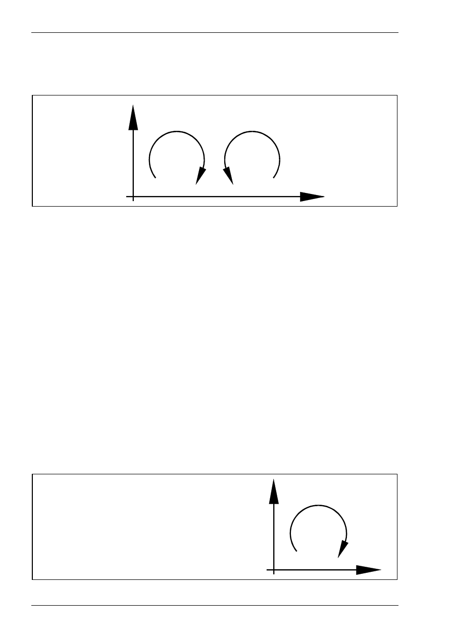
4.2 Circular interpolation
Circular interpolations can be moved in two opposite directions.
G02 in clockwise direction, or in
G03 counter-clockwise direction.
X
Y
G 02
G 0 3
Directions for Circular Interpolations.
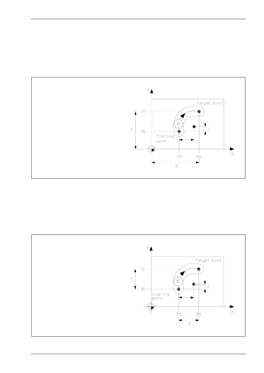
4.2.1 Circular Interpolation Clockwise G02
Command:
G02
Circular Interpolation Clockwise G02
Function:
The tool will move clockwise on a circular arc to the target position.
NC-Block:
G02 [X...] [Y...] [Z...] [I...] [J...] [K...] [F...]...
Optional Addresses:
X
X-Coordinate of the Target Point
Y
Y-Coordinate of the Target Point
Z
Z-Coordinate of the Target Point
I
Circle Center Incremental (distance between the starting position and the
circle center in the X-direction).
J
Circle Center Incremental (distance between the starting position and the
circle center in the Y-direction).
K
Circle Center Incremental (distance between the starting position and the
circle center in the Z-direction).
Note:
The addresses I, J and K are always programmed in the incremental system, re-
gardless of the selected value command system (G90 or G91).
F
Feedrate
The tool will move at the programmed feedrate
clockwise on a circular arc to the target position as
defined by the coordinates in X and Y.
These coordinates may either be programmed in
the absolute system (G90) or in the incremental
system (G91).
X
Y
G 0 2
Interpolation with cutter radius compensation
© MTS GmbH • Berlin
59
Command:
G02
Circular Interpolation Clockwise G02
Function:
The tool will move clockwise on a circular arc to the target position.
NC-Block:
G02 [X...] [Y...] [Z...] [I...] [J...] [K...] [F...]...
Programming Example
with Absolute Coordinates:
N085 G90
N090 G00 X+55. Y+35. Z+2.
N095 G01 Z-5.
N100 G02 X+95. Y+75. I+30. J+10.
Please note that in the absolute system the target points must be programmed according to their position in
the coordinate system with reference to the origin of that system.
Programming Example
with Incremental Coordinates:
N085 G00 X+55. Y+35. Z+2.
N090 G91
N095 G01 Z-7.
N100 G02 X+40. Y+40. I+30. J+10.
Interpolation with cutter radius compensation
© MTS GmbH • Berlin
75
Tool approach and retreat movements
The cutter radius compensation is activated within a block. This means that the cutter radius compensation
must at the latest be selected when the first contour point is approached.
Activate Cutter Radius Compensation
Additionally, contour-parallel or tangential approaching motions are also often programmed.
Contour-parallel Approach
Tangential Approach in a Quadrant
Interpolation with cutter radius compensation
© MTS GmbH • Berlin
79
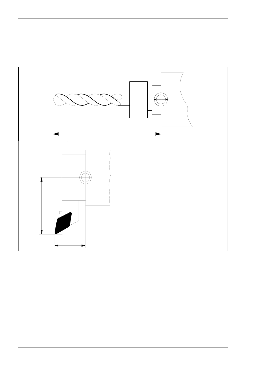
4.5 Tool length compensation
Using the tool compensation values it is easy to program a work part without directly considering the applica-
ble tool lengths or tool radii. The available work part drawing data can be directly used for programming. The
tool data, lengths as well as radii of the milling machines or indexable inserts are automatically considered by
the CNC control.
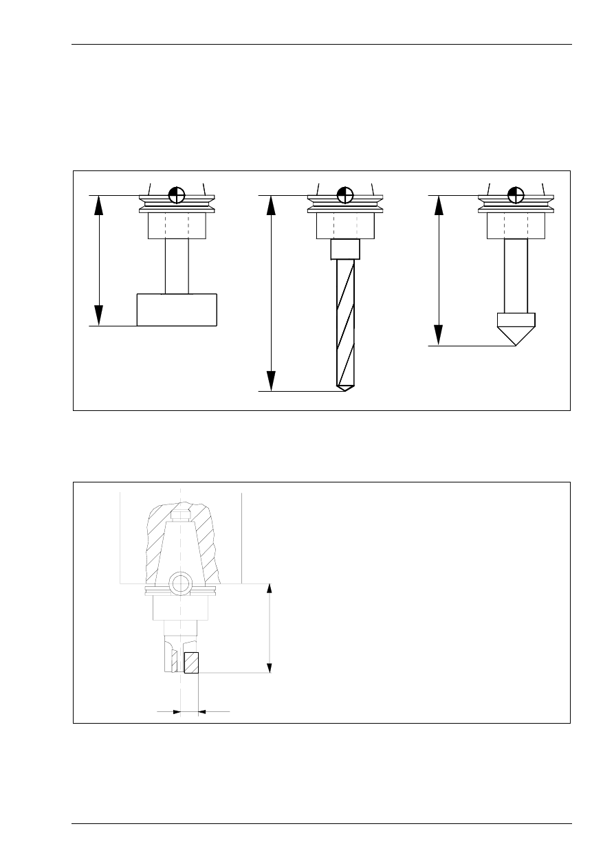
L 1
L 2
L 3
T-slot cutter
drill
core drill
When programming an NC-program in absolute dimensioning, the control requires a coordinate system as
well as information on the lengths of all employed tools. For this it is necessary to measure the length L, i.e.
the distance between the tool setup point B and the cutting tip, and to enter it into the control.
B
R
L
B
tool setup point
L
length = distance of the cutting tip to the
tool setup point in Z
R
radius of the milling tool
Tool compensation values
A tool length compensation with reference to the reference point enables the adjustment between the set and
actual tool length, as in the case of finishing the tool. This tool length value has to be available to the control.
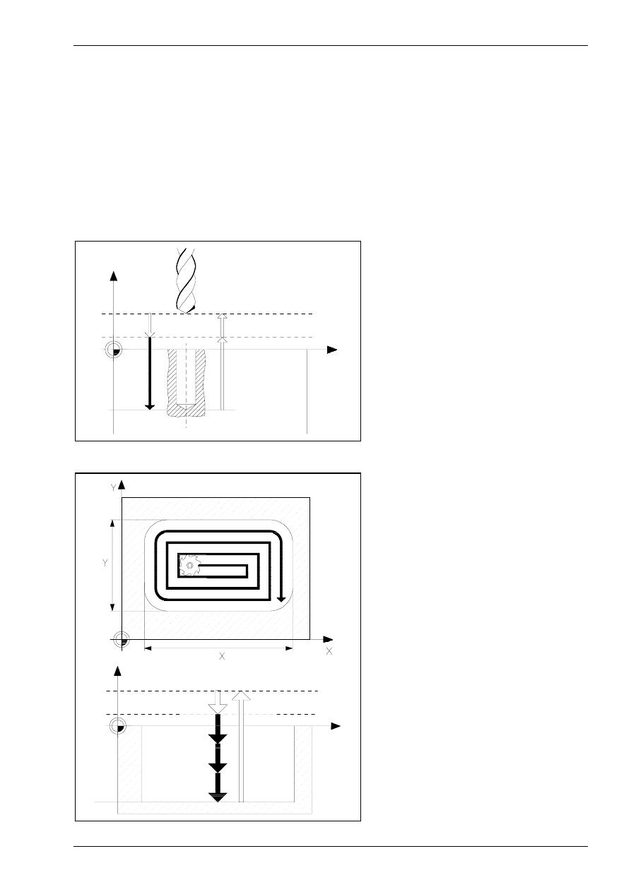
Function and use of cycles
© MTS GmbH • Berlin
85
5 Cycles
5.1 Function and use of cycles on a CNC milling machine
In CNC-controls, predefined machining cycles are available which can be invoked with specific commands.
Similar to subprograms, they contain prevalent command sequences. These machining cycles can be divided
into three different types:
•
drilling cycles
•
milling cycles
•
special cycles
Drilling cycles
in itia l p o in t
Z
X
sa fe ty p lan e
d ep th
For drilling cycles, also called canned
cycles in the FANUC-control, specific
drilling, reaming or threading tasks are
programmed by a command in conjunc-
tion with information on the required pa-
rameter. The CNC-control then executes
all operations, e.g. for threading.
Milling cycles
in itial point
Z
X
safety plan e
d epth
For milling cycles, also called macro in
the FANUC-control, specific milling op-
erations, e.g. circular or rectangular
pockets, are executed. For these cycles,
the CNC-control must perform extensive
calculations, e.g. to generate the individ-
ual travel motions for a rectangular
pocket.
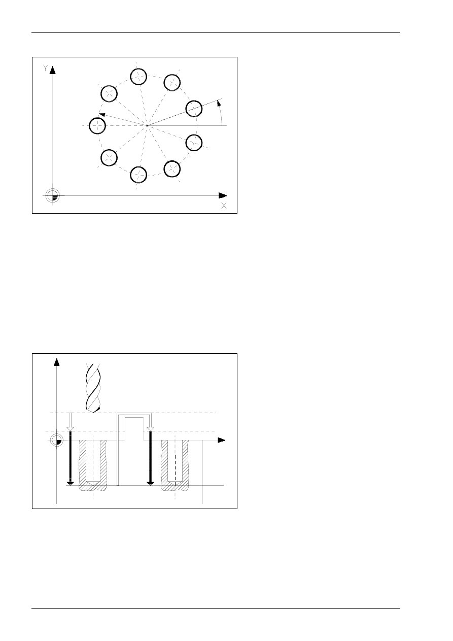
Chapter 5
86
MTS TeachWare • CNC-Milling • Student’s Book
Special cycles
Belonging to the special cycles are e.g.
various drill patterns. Combined with
drilling cycles, e.g. holes on a circle or in
a row can thus be easily programmed.
Safety planes
Multiple repetition of these cycles is common e.g. with drilling holes on a divided circle or on a straight line.
initia l po in t
Z
X
safety p lan e
de p th
In the execution of a repeated cycle the
tool will be retracted to the initial point
before moving (in rapid traverse motion)
to the next target position.
Programming the Z-coordinate of this
initial point (the Y- or X-coordinate ac-
cordingly, if G18 or G19 have been pro-
grammed in the machining plane selec-
tion) is not necessary, it will be estab-
lished from the actual tool position at the
moment of the cycle invocation.
Please make sure that the Z-coordinate of this initial point (i.e. the position of the retracted tool) is sufficiently
defined above the work part contour. After the cycle is invoked, the tool must be positioned to the
Z-coordinate of this initial point. Subsequently the tool will be moved in the rapid traverse mode from this Z-
position down to the safety plane.
After completion of the cycle the tool is retracted in a rapid motion to the Z-coordinate of the initial point.
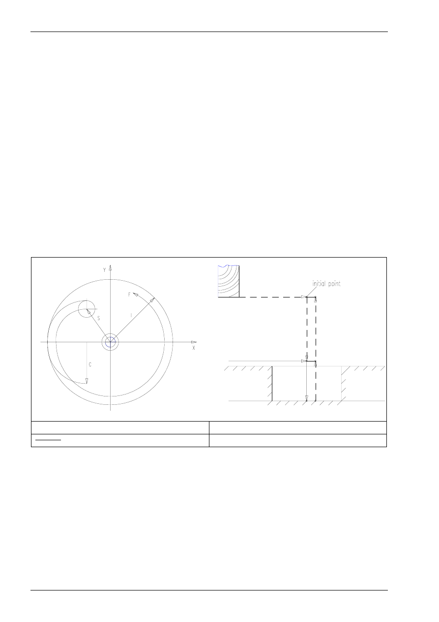
Chapter 5
144
MTS TeachWare • CNC-Milling • Student’s Book
5.3.4 finishing inside of circle macro P9110
Command:
G65 P9110
finishing inside of circle
NC-Block:
G65 P9110 I... D... R... Z... F... C... S... Q... M...
Optional Addresses:
I
cutting circle radius
D
cutter radius offset number
R
Z-position of the safety plane
Z
Z-position of the bottom of the pocket
F
feedrate
C
approach circle radius
S
approach feedrate
Q
cutting direction
M
setting mode for R and Z
Z
R
- - - - : rapid traverse
R : safety plane
: cutting feed
Z : depth
Note:
The offset value must be less than the approach circle radius.
The cutter radius compensation is used.
Specify Q1. for counterwise cutting direction and omit Q for counter-clockwise cut-
ting direction.
Specify M1. for incremental values of R and Z.
Omit M for absolute values of R and Z.
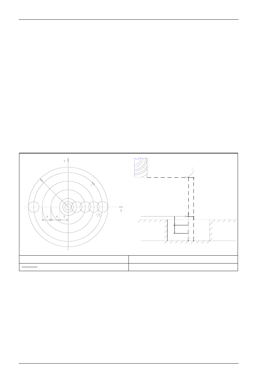
Chapter 5
146
MTS TeachWare • CNC-Milling • Student’s Book
5.3.5 deep cutting of circular pocket macro P9120
Command:
G65 P9120
deep cutting of circular pocket
NC-Block:
G65 P9120 I... D... H... R... Z... F... S... Q... M...
Optional Addresses:
I
cutting circle radius
D
cutter radius offset number
H
cutting width per pass
R
Z-position of the safety plane
Z
Z-position of the bottom of the pocket
F
feedrate
S
approach feedrate
Q
infeed per pass
M
setting mode for R and Z
nitial point
Z
Q
R
Q
- - - - : rapid traverse
R : safety plane
: cutting feed
Z : depth
Note:
Specify H so that it is less than the cutter diameter.
Only the counter-clockwise cutting direction is available..
Specify Q1. for counterwise cutting direction and omit Q for counter-clockwise cut-
ting direction.
Specify M1. for incremental values of R and Z.
Omit M for absolute values of R and Z.
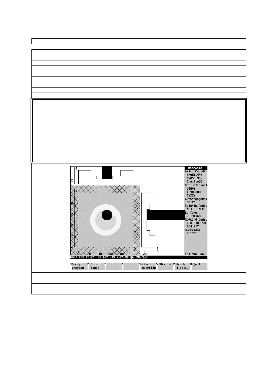
Function and use of cycles
© MTS GmbH • Berlin
147
Programming Example for the macro: G65 P9120 deep cutting of circular pocket
$G54 X400 Y250 Z140
O 120
N010
G54
N015
G90 G49 G80 G40 G17 G21
N020
G91 G28 Z0 M9
N025
G91 G28 X0 Y0
N030
T02 M6
N035
G90 S1800 M3
N040
G0 G43 Z20 H18
N045
X50 Y50 M8
N050
G65 P9120 I30 D2 H15 Z-20 R2 Q6 F60 S30
P9120 deep cutting of circular pocket
I30
cutting circle radius
D2
cutter radius offset number
H15
cutting width per pass
Z-20
Z-position of the bottom of the pocket
R2
Z-position of the safety plane
Q6
infeed per pass
F60
feedrate
S30
approach feedrate
N055
G0 Z20 M9
N060
G91 G28 Z0 M5
N065
G90 G49 G80 G40
N070
M30
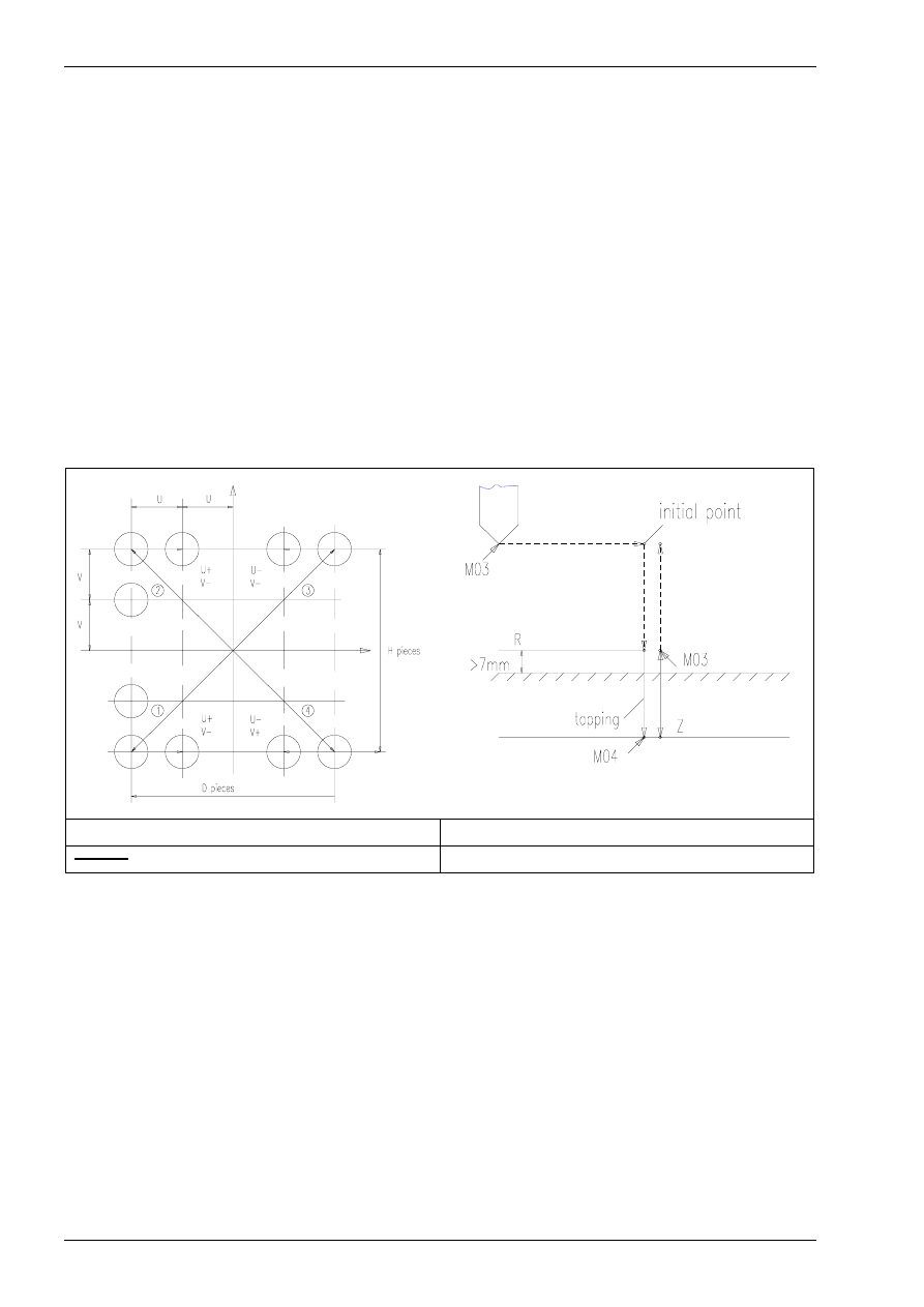
Chapter 5
158
MTS TeachWare • CNC-Milling • Student’s Book
5.3.10 matrix maching macro P9200
Command:
G65 P9200
matrix maching
NC-Block:
G65 P9200 X... Y... U... D... V... H... S...
Optional Addresses:
X
X coordinate of the first hole
Y
Y coordinate of the first hole
U
pitch in X-direction
D
number of holes in X-direction
V
pitch in Y-direction
H
number of holes in Y-direction
S
subprogram number called
for example tapping cycle G84
- - - - : rapid traverse
R : safety plane
: cutting feed
Z : depth
There are two possibilities to use the bolt hole circle:
1) for drilling:
G90 G98 G84 Z-30 R7 P1000 F1000 L0
G65 P9200 X... Y... U... D... V... H...
G80 X... Y...
2) for multi-block machining
G65 P9200 X... Y... U... D... V... H... S...
Note:
Use the absolute input value (G90) for positioning.
Don´t specify S by programming a canned cycle (first possibility).
The subprogram must be programmed with incremental
value input (second possibility).
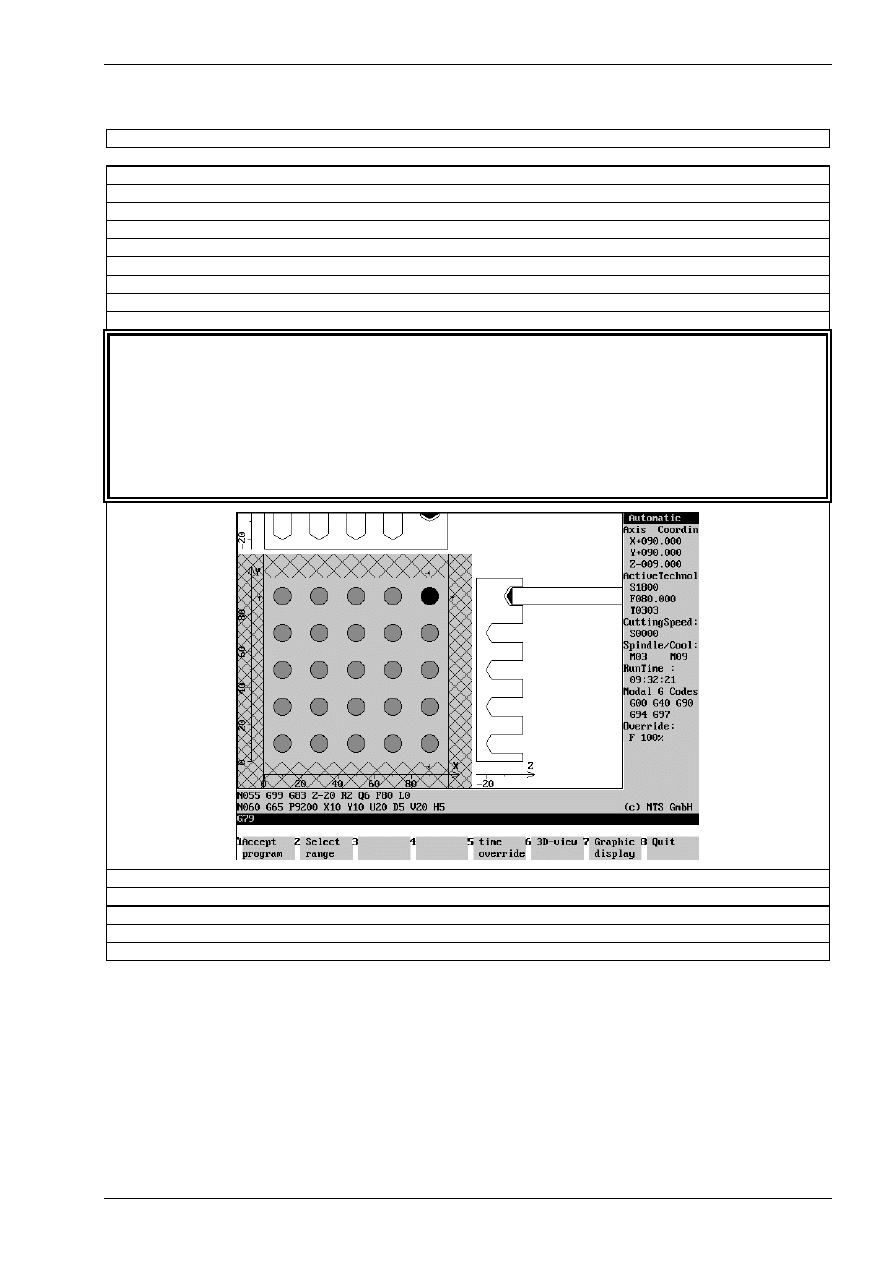
Function and use of cycles
© MTS GmbH • Berlin
159
Programming Example for the macro: G65 P9200 matrix machining for drilling
$G54 X400 Y250 Z135
O 200
N010
G54
N015
G90 G49 G80 G40 G17 G21
N020
G91 G28 Z0 M9
N025
G91 G28 X0 Y0
N030
T03 M6
N035
G90 S1800 M3
N040
G0 G43 Z20 H19 M8
N045
G99 G83 Z-20 R2 Q6 F80 L0
definition of a peck drilling cycle
N050
G65 P9200 X10 Y10 U20 D5 V20 H5
P9200 matrix machining
X10
X coordinate of the first hole
Y10
Y coordinate of the first hole
U20
pitch in X-direction
D5
number of holes in X-direction
V20
pitch in Y-direction
H5
number of holes in Y-direction
N055
G80
N060
G0 Z20 M9
N065
G91 G28 Z0 M5
N070
G90 G49 G40
N075
M30
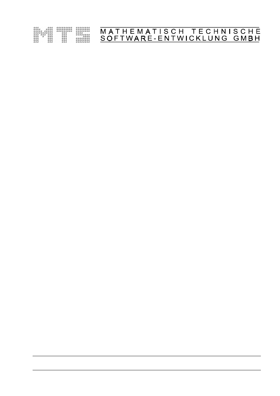
CAD/CAM Turning & Milling
with MTS INCAD
MTS TeachWare Student’s Book -
Excerpt
MTS Mathematisch Technische Software-Entwicklung GmbH • Kaiserin-Augusta-Allee 101 • D-10553 Berlin
Phone: +49 / 30 / 349 960-0 • Fax: +49 / 30 / 349 960-25 • World Wide Web: http://www.mts-cnc.com • email: mts@mts-cnc.com

CAD/CAM Milling
© MTS GmbH • Berlin
113
3 CAD/CAM Milling
3.1 From a drawing to a finished work part:
In contrast to manual NC-programming the CAD-CAM-system supports the programmer in many aspects.
The system does some of the preparing work for example the computing of not measured contour points.
The system directly takes the geometries, so the input (coordinates etc.) is automatically right.
Using a cutting value table cutting speed etc. can be set automatically.
For automatic programming the sequence of operations for generating an NC-program is as follows:
1. First the work part must be geometrically defined. A representation of the finished part as
well as the blank is necessary.
2. Subsequently, the individual machining operations are specified. The programming system
assists the programmer in selecting the appropriate tool and automatically calculates the
necessary cutting data.
3. Finally a NC-program for a specific CNC-machine tool with a specific CNC-control is
generated and can then be transferred to the machine.
It follows a description of these steps.
3.1.1 basic concept on the use of CAD data for NC production in milling
The main goal of a CAD-system has been a simplified generation of technical drawings. Advantages lie in the
possibility of making changes easily, copying and printing several times the drawing.
Using the CAD-system only the drawing itself was generated, other information like measures or tolerances
had to be set manually.
The CAD-CAM-system has a much wider range of tasks. The system should generates directly from the
drawing NC-blocks for the production of the part. This means all points and contour elements have to be in
the system with required tolerance.
From this follows:.
the input of each coordinate has to be done with the highest precision possible.
You should use numerical input or the other help functions like auxiliary contours or trapping functions.
Contours can be used in the CAD-CAM-system for automatically generation NC-programs, if the construction
has been done appropriate. Every contour has to be a „contour string“. The INCAD-system supplies the
function „contour string“ and a „contour tracing“ function, if elements of a contour are not generated using
„contour string“.
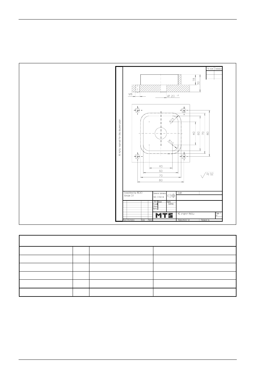
CAD/CAM Milling
116
MTS TeachWare • CADCAM • Student’s Book
3.1.5 CAD/CAM drawing
We want describe the function and the using of the INCAD-system milling by programming the NC-program
for the following plate. It is to be manufactured as individual workpart on a CNC milling machine.
blank
100 x 100 x 30 mm
clamping height 70 mm
material
AlMgSi1
P L AT E
WORK PLAN
contour milling
T01
shell end mill
MW-040/032 HSS ISO 2586
pocket milling
T11
slot milling tool
MS-18.0/063L HSS ISO 1641
core hole drilling
∅
6.8 T12
drill
DR-06.80/069 HSS ISO 235
threading M8
T02
tap
TA-M08.0/1.25 HSS ISO 2857
predrilling
∅
19.8
T04
step drill
DS-19.8/11.5-118 HSS ISO 3439
reaming 20H7
T08
reamer
RE-D20.0/H7 HSS ISO 521
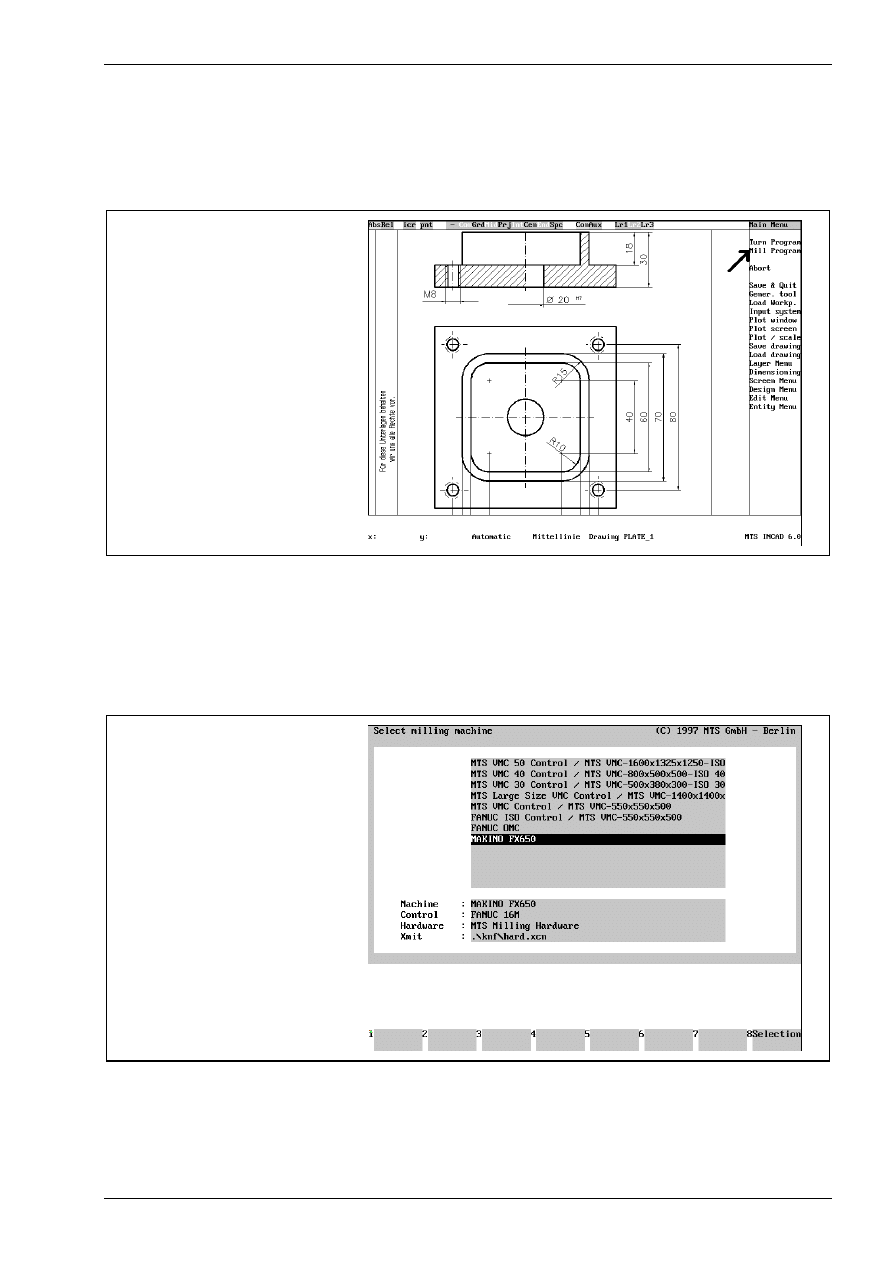
CAD/CAM Milling
© MTS GmbH • Berlin
119
3.2.1 Starting NC programming system milling
Before starting the mill program you should choose a zoom window, so that only necessary elements are
visible.
activating CADCAM-System
milling
3.2.2 Selecting CNC machine
Starting the mill program some steps have to be done (only once) as a basis for what follows. They are
necessary and cannot be changed during generation of the NC-program.
selection of milling machine
„MAKINO FX 650“
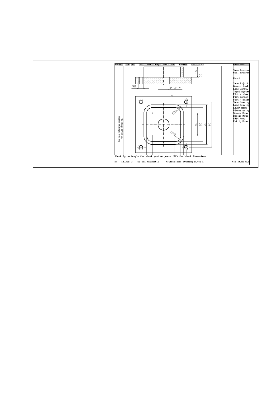
CAD/CAM Milling
© MTS GmbH • Berlin
121
3.2.4 Defining the location of workpart zero point
Every NC-program requires a workpart zero point, to which measures relate. You choose this point before the
programming, if necessary, it can be changed later by using zero point shifts.
defining the blank
You identify the blank part in a dialog:
Identify rectangle for blank part or press <F2> for blank dimensions!
Click with the mouse to identify the blank part in the top view. Then you have to enter the height or identify it
in the front view.
Enter height numerically : <F1>, define by 2 points : <F2> !
Pushing the <F1> key you see the following prompt:
Enter blank height !
Now you can enter the height, in this example 30mm.
Selecting the work part zero point the clamping situation has to be taken into account. In this example there
are some go through holes, so there has to be a distance to the machine table. The procedure is the same as
with the height:
<F1> for clamping height numerically, <F2> for defining by two points !
Pushing the <F1> key you see the following prompt:
Clamping height :
In our example we use the clamping height 70 mm.
Note:
With the machine MAKINO FX650 we have a special machine configuration:
The machine range in the Z-axis begins with 150mm. This value has to be added to
the clamping height. Therefore the clamping height = 0 is not allowed!
In our example we enter a clamping height of 220mm!
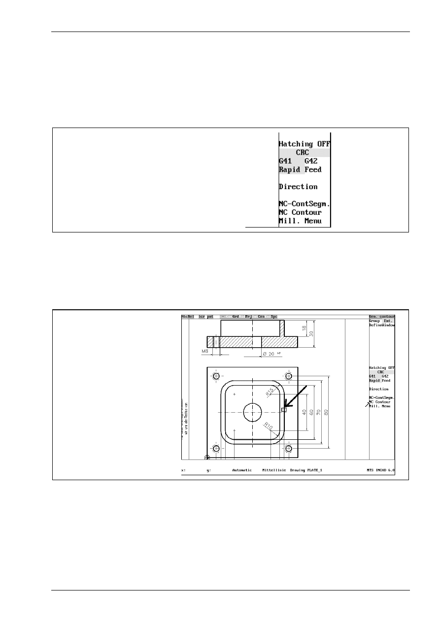
milling contours
© MTS GmbH • Berlin
131
NC program generation: contour milling
Activating the function „Contours“ starts the generation of NC-commands.
cutter radius compensation
Before selecting the contour you can activate cutter radius compensation and choose the position of tool
relative to the contour. To do this, activate the appropriate switches with the mouse.
G41
tool left to contour
G42
tool right to contour
switches for contour milling
The positioning movement can be in rapid speed or in infeed. In most cases the tool will move in rapid speed,
to do so, set the switch „Rapid/Feed“ with the mouse to „Rapid“.
selecting a NC contour to be machined
After activating the function „NC Contour“ you start with the selection of the contour to be milled through the
following dialog.
Identify NC-entity at the start point !
select a contour
With the mouse select the contour, which is marked then by colour.
This entity <F2>, Next entity <F1>
With <F2> yyou confirm this contour. Pushing <F2> a second time marks the passing direction of the tool. If
this direction is not correct, you can change it with the function „Direction“.
Press <F1> to generate NC-program , <F3> to abort !
With <F1> you confirm every input.
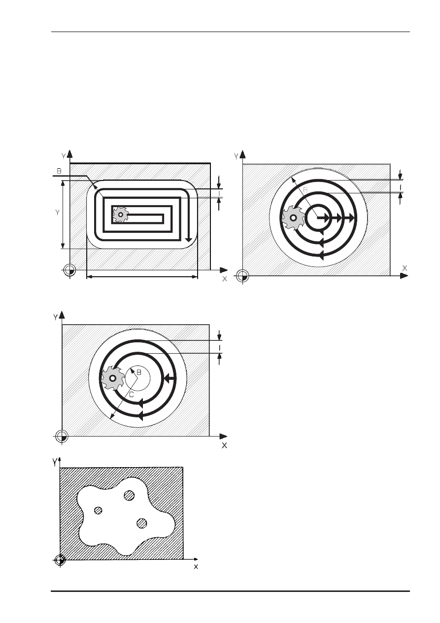
milling pockets
© MTS GmbH • Berlin
133
3.2.7 Pockets
With the INCAD-system you can create NC-commands for manufacturing pockets. You have to enter the
necessary technological data or activate existing ones. The geometric data are automatically created through
the graphical selection in INCAD. You have to consider, that a contour is a rectangle, circle or „contour
string“.
Following different pocket/pin cycles are available:
G87- Rectangular pocket cycle
G88 - Circular pocket cycle
G89 - Pin cycle
G01/G02/G03-G41/G42
Contour pocket with islands
Alternative clockwise / counterclockwise
Starting point for downfeed
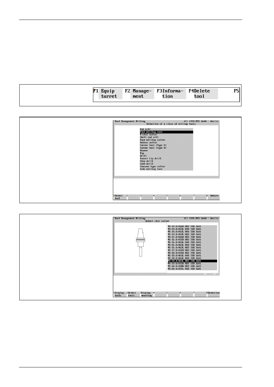
CAD/CAM Milling
134
MTS TeachWare • CADCAM • Student’s Book
tool selection
First we choose a slot milling tool with a diameter of 18 mm and place it at position nr. 2 in the magazine.
We click the menupoint „tools“ with the mouse.
First we select with the cursor the second position, so that its frame is marked then. Then we open the
window for selecting tool groups with <F1> „Equipmagazine“ and mark the chosen class of milling tools.
select „Equip turret“
with <F1>
select with the arrow taste the
class of milling tool
„slot milling tool“
and confirm with<F1>
In the menu for slot milling tools select one tool and confirm with <F8>.
Select with the arrow taste the
slot milling tool
„MS-18.0/063L HSS ISO 1641“
and confirm with<F8>

drilling
© MTS GmbH • Berlin
139
3.2.8 Drilling
With INCAD you can create NC-commands for drilling, trapping and reaming. You have to enter all necessary
technological data or activate existing ones. All geometric data are automatically generated by INCAD after
related shapes are selected. Take into consideration that all boreholes are represented by circles!
Following different drilling cycles are available:
G81 - Drilling cycle
G82 - Drilling cycle with chip breaking
G83 - Drilling cycle with chip breaking and chip-removal
G84 - Tapping cycle
G85 - Reaming cycle
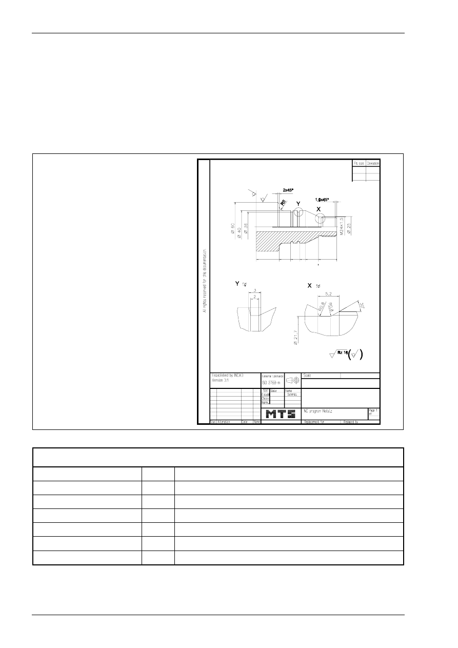
CAD/CAM Turning
174
MTS TeachWare • CADCAM • Student’s Book
4 CAD/CAM Turning
4.1 NC program generation turning
4.1.1 CAD/CAM drawing
We want describe the function and the using of the INCAD-system turning by programming the NC-program
for the following bolt. It is to be manufactured as individual workpart on a CNC turning machine.
blank
∅
65mm x 102mm
chucking depth
22mm
material
AlMgSi1
B O LT
22
38
+0
.1
-0
.1
+0
.1
-0
.1
45
56
70
98
WORK PLAN
face turning
T01
left handed corner cutter
centring
T11
centring tool
drilling
T12
twist drill
contour roughing
T02
left handed corner cutter
contour finishing
T04
left handed corner cutter
recessing
T06
external recessing tool
threading
T08
left handed threading tool
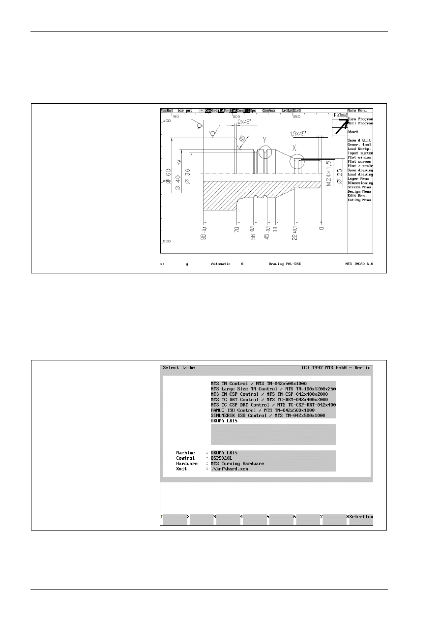
CAD/CAM Turning
176
MTS TeachWare • CADCAM • Student’s Book
4.1.2 Starting the NC programming system turning
Before starting the turn program you should choose a zoom window, so that only necessary elements are
visible.
calling CADCAM-System turning
4.1.3 Selecting the CNC machine
Starting the turn program some steps have to be done (only once) as a basis for what follows. They are
necessary and cannot be changed during generation of the NC-program.
selecting the turning machine
„OKUMA LB15“
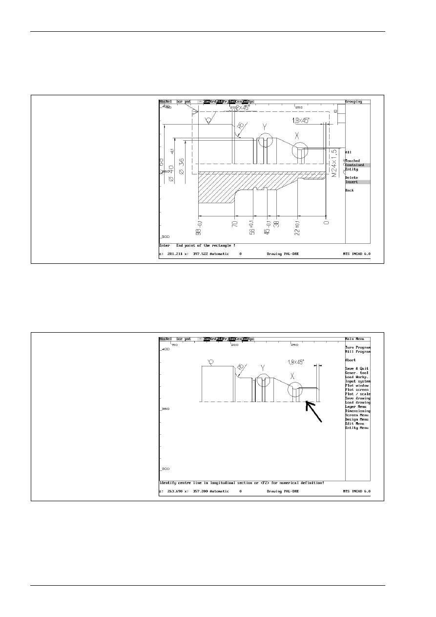
CAD/CAM Turning
178
MTS TeachWare • CADCAM • Student’s Book
4.1.5 selecting drawing elements for NC programming
For the following programming steps the necessary grafical entities must be selected.
<F1> : Select entities , <F2> entire drawing, <F3> abort !
selecting entities
By presssing the <F1> key the following dialog appears:
Enter start point of the rectangle !
Enter end point of the rectangle !
Use the mouse to create a rectangle which contains all necessary entities. The selected entities are marked
with another colour. Confirm the selection by calling the „back“ function with the mouse.
selected entities
The centre line must be selected with the mouse.
Identify centre line in longitudinal section or <F2> for numerical definition
Finally the workpart must be selected with the mouse and confirmed with<F1>.
Identify workpart in longitudinal section !
<F1>: Accept entity as workpiece, <F2>: another piece !
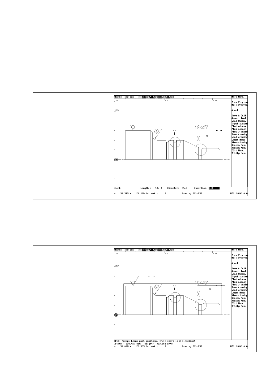
CAD-CAM Turning
© MTS GmbH • Berlin
179
4.1.6 defining blank
The INCAD-system hides all unselected entities, generates a new view from the workpart and shows
information about his volume and his weight.
Part data: (<F1> to continue)
Volume : 141.520 ccm Weight : 382.102 grams
By pressing the <F1> key the following dialog for the blank dimension appears:
Blank
Length = 102.000
Diameter = 65.000
InnerDiam. 0.0
defining blank
Use the tastatur to write the desired dimensions or confirm with the <Enter> key. The INCAD-system asks for
a centring of the blank by the following prompt.
Centring ? (Y/N) N
The standard answer from the system is No. Confirm it by pressing <Enter> .
Finally a shift of the blank can be entered by the following dialog
<F1>: Accept blank part position, <F2>: shift in Z-direction!
blank part
Confirm the blank part position with the <F1> key.
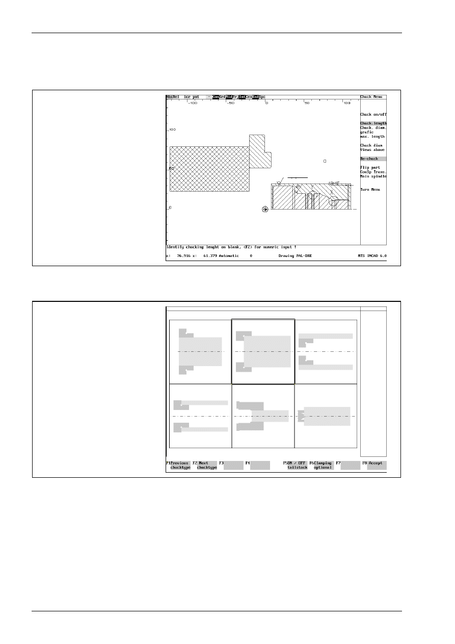
CAD/CAM Turning
180
MTS TeachWare • CADCAM • Student’s Book
4.1.7 Selecting clamping devices
The INCAD-system offers a chuck.
offered chuck
You can choose the chuck by calling the „Main spindle“ function with the mouse. Use the <F1> or <F2> key
to select the desired chucktype.
selecting a chuck
Press <F8> to confirm your choice.
Select the chuck „ KFD-HS 160“ by pressing <F8> (Return).
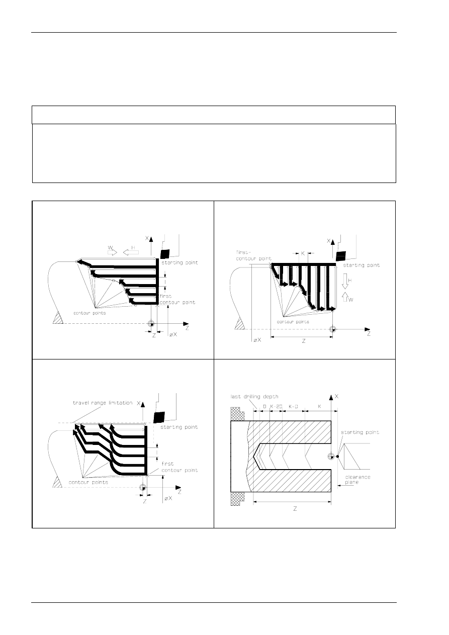
CAD/CAM Turning
184
MTS TeachWare • CADCAM • Student’s Book
4.1.11 survey over possible machining sequences
Machining sequences and procedures you have to use in MTS-Code independant of your selectedmachine
and control. With a postprocessor the system generates an NC-program in the control language of your
control for example OKUMA.
SURVEY OF PROCESS CAPABILITIES
Cycles
G81
Straight Roughing Cycle / Optional contour
G82
Cross Roughing Cycle / Optional contour
G83
Contouring cycle - Multipass cycle
G84
Deep drilling cycle
G31
Threading cycle
G79
Recessing cycle
G81
Straight Roughing Cycle / Optional contour
G82
Cross Roughing Cycle / Optional contour
G83
Contouring cycle - Multipass cycle
G84
Deep drilling cycle
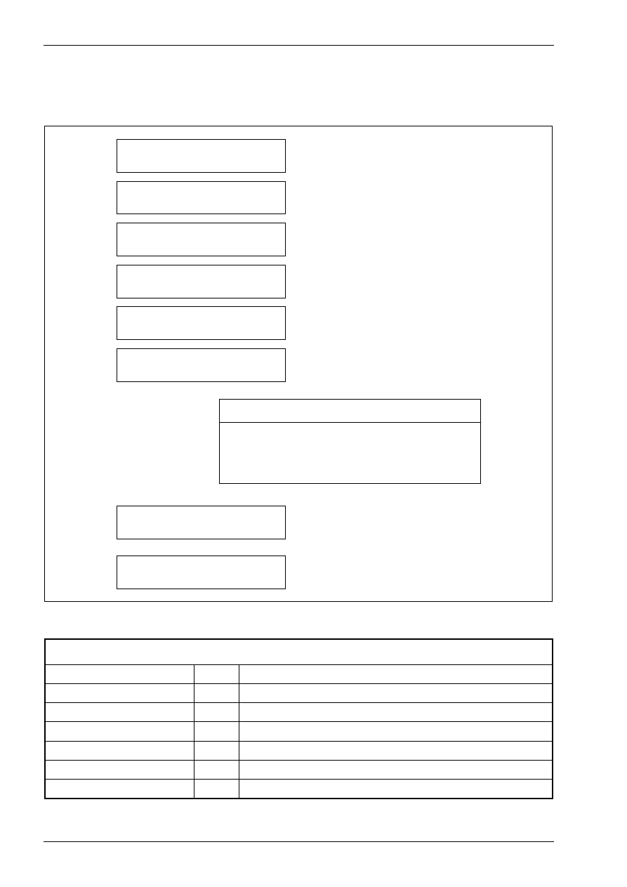
CAD/CAM Turning
186
MTS TeachWare • CADCAM • Student’s Book
4.2 programming the machine sequences
In principle this is the procedure for generating NC-programs:
2 . sta rtin g
N C p ro g ra m m in g sy ste m tu rn in g
3 . sele cting
the C N C -m a c h in e
5 . d e fin in g th e lo catio n
o f w o rkp a rt ze ro p o in t
6 . p ro g ra m m in g
the m a ch inin g se q u e n ce s
7 . sa v in g
the g e n e ra te d N C -pro g ra m
8 . sim ula tin g
the g e n e ra te d N C -pro g ra m
4 . sele cting
the b la nk m a te rial
1 . lo a d in g
a q u a lifie d C A D file
p ro g ra m m in g a m ac h in ing s e q u e n ce
to o l se le ctio n
d e fin in g te c h n o lo g ica l va lue s
s e le c tin g c o n to u rs fo r g e o m etric a l da ta
d e fin in g a p p roa ch a n d w ith d ra w a l s tra te g y
With the following machining sequences we´ll describe the possibilities of the CAD-CAM-system.
WORK PLAN
face turning
T01
left handed corner cutter
centring
T11
centring tool
drilling
T12
twist drill
contour roughing
T02
left handed corner cutter
contour finishing
T04
left handed corner cutter
recessing
T06
external recessing tool
threading
T08
left handed threading tool
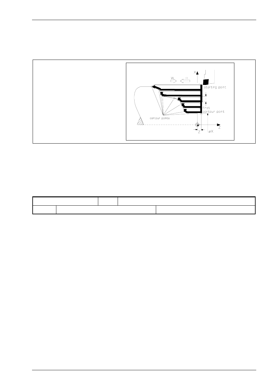
straight roughing
© MTS GmbH • Berlin
193
4.2.4 Straight roughing
The cycle G81 is a straight roughing cycle with movements parallel to the Z-axis by selecting an contour. It
can be programmed for either internal or external machining.
straight roughing cycle
At first activate the function „straight roughing Cycle“ by selecting the menupoint „convnt.Tools“ with the
mouse and after that the menupoint „Straight rgh“.
tool selection
In the work plan an the set-up sheet the following machining sequence and tool are described.
contour roughing
T02
left handed corner cutter
T02
left handed corner cutter
CL-SVJCL-2020/L/1604 ISO30
We click the menupoint „tools“ with the mouse. First we select with the cursor the second position, so that its
frame is marked then. Go back to the turn menu by confirming with <F8>.
defining technological values
For the machine sequence „contour roughing“ cutting values are required. You can get these data
automatically from the INCAD-system by activating the function „CutValuesOn“.
In the following dialog you can confirm all answers with <Enter> or change if desired the value with the
keyboard. In our example we confirm all.
Coolant M08
Feed(mm/rev): 0.25
m/min: 200
Speed lim. 3500
Move to the tool changing point: Y
Approach opt.: 0
CRC : N
Autofinish N
Downfeed: 2.00
Finishing allowance Z :0.2
Finishing allowance X :0.2
Finishing allowance parallel :0.0
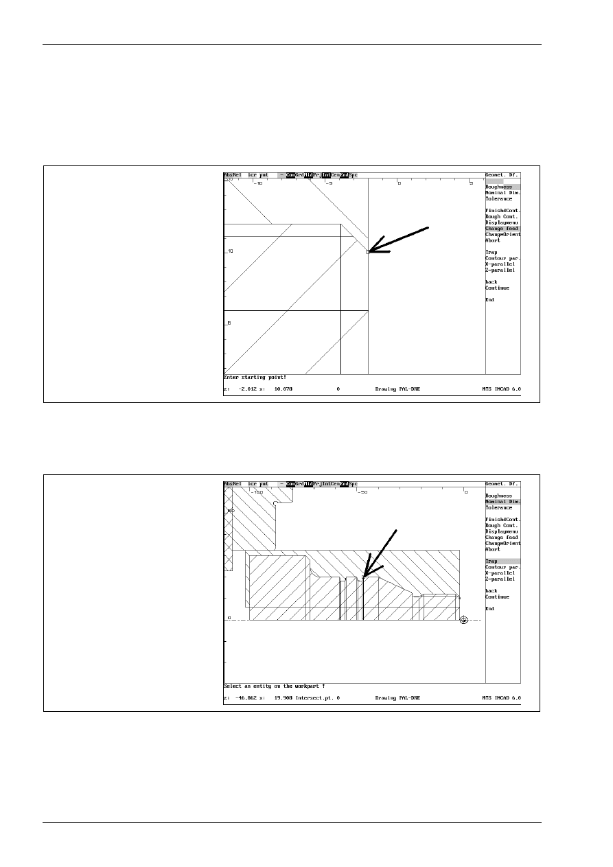
CAD/CAM Turning
194
MTS TeachWare • CADCAM • Student’s Book
selecting the contour to be machined
The system asks for the starting point of the contour
Enter starting point !
Use the zoom function with <F6> for showing the details. Click with the mouse at the following point. Use the
automatic trapping function by selecting in the swith line.
starting point
Enter next point !
The system asks for the next point. Activate the trap function with the switch „Trap“ and click with the mouse
at the following point.
next point of the contour
using the function „Trap“
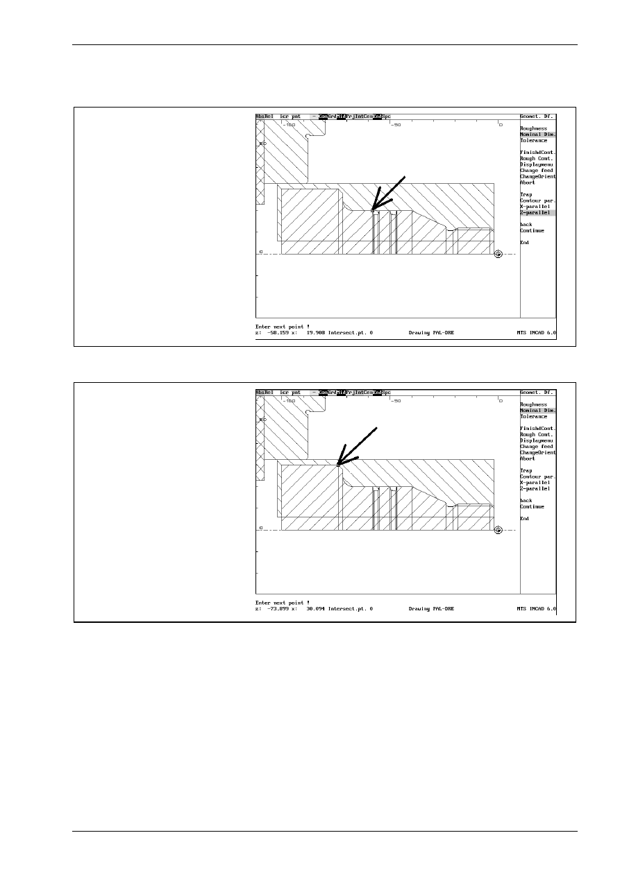
straight roughing
© MTS GmbH • Berlin
195
Now activate the the switch „Z-parallel“ and click with the mouse at the following point.
next point of the contour
using the function „Z-parallel“
Use again the trap function with the switch „Trap“ and click with the mouse at the following end point
end point of the contour
using the function „Trap“
Confirm these entries with the menupoint „End“
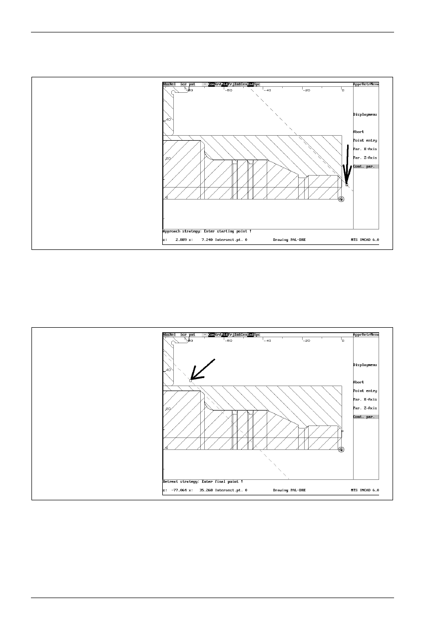
CAD/CAM Turning
196
MTS TeachWare • CADCAM • Student’s Book
defining approach and withdrawal strategy
For the approach movement activate the function „Cont. par.“ and click right of the workpart.
approach movement
Enter the distance to the workpart with the keyboard
Incremental value : 1
and confirm with <Enter>. The following prompt appears:
Retreat strategy: Enter final point !
For the retrat movement activate the function „Cont. par.“ and click over the workpart.
retreat movement
Enter the distance to the workpart with the keyboard
Incremental value : 4
and confirm with <Enter>. At least confirm all with <F1> three times.
<F1> to accept starting and end points, <F2> other selection
<F2> to entr the cycle invocatn oint, <F1> to cont. !
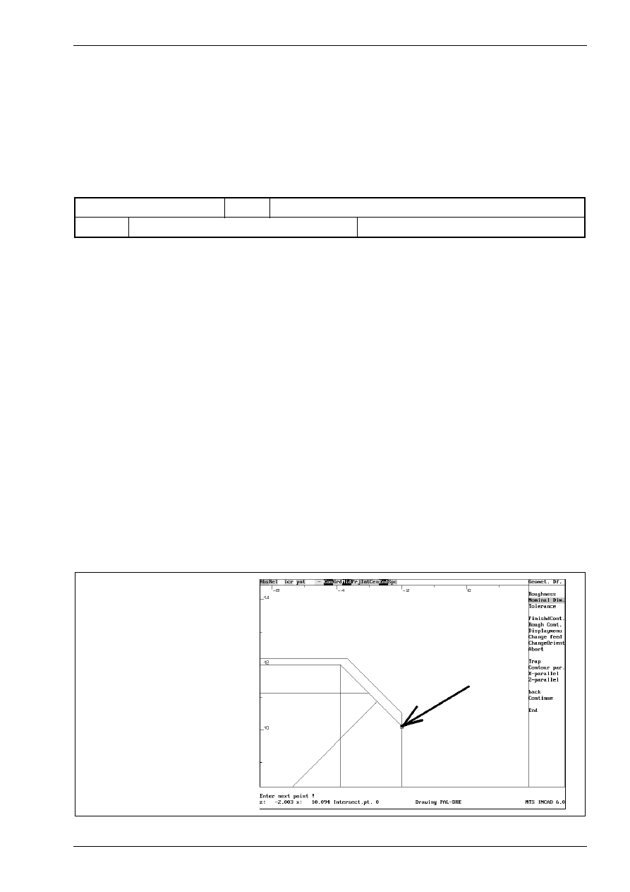
finishing contours
© MTS GmbH • Berlin
197
4.2.5 Finishing contours
At first activate the function „finishing contours“ by selecting the menupoint „convnt.Tools“ with the mouse
and after that the menupoint „Finishing“.
tool selection
In the work plan and the set-up sheet the following machining sequence and tool are described.
contour finishing
T04
left handed corner cutter
T04
left handed corner cutter
CL-SVJCL-2020/L/1604 ISO30
We select with the cursor the fourth position, so that its frame is marked then. Go back to the turn menu by
confirming with <F8>.
defining technological values
For the machine sequence „contour finishing“ cutting values are required. You can get these data
automatically from the INCAD-system by activating the function „CutValuesOn“.
In the following dialog you can confirm all answers with <Enter> or change if desired the value with the
keyboard. In our example we confirm all.
Coolant M08
Feed(mm/rev): 0.10
m/min: 300
Speed lim. 3500
Move to the tool changing point: Y
Approach opt.: 0
selection of the contour to be machined
The system asks for the starting point of the contour
Enter starting point !
Use the zoom function with <F6> for showing the details. Click with the mouse at the following point. Use the
automatic trapping function „Int“ by selecting in the swith line.
starting point
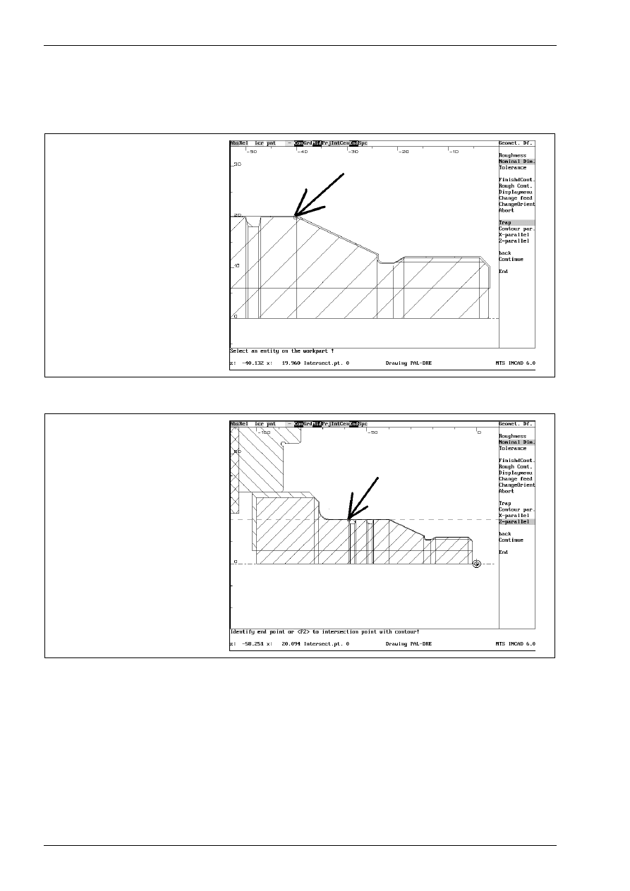
CAD/CAM Turning
198
MTS TeachWare • CADCAM • Student’s Book
Enter next point !
The system asks for the next point. Activate the trap function with the switch „Trap“ and click with the mouse
at the following point.
next point of the contour
using the function „Trap“
Now activate the the switch „Z-parallel“ and click with the mouse at the following point.
next point of the contour
using the function „Z-parallel“
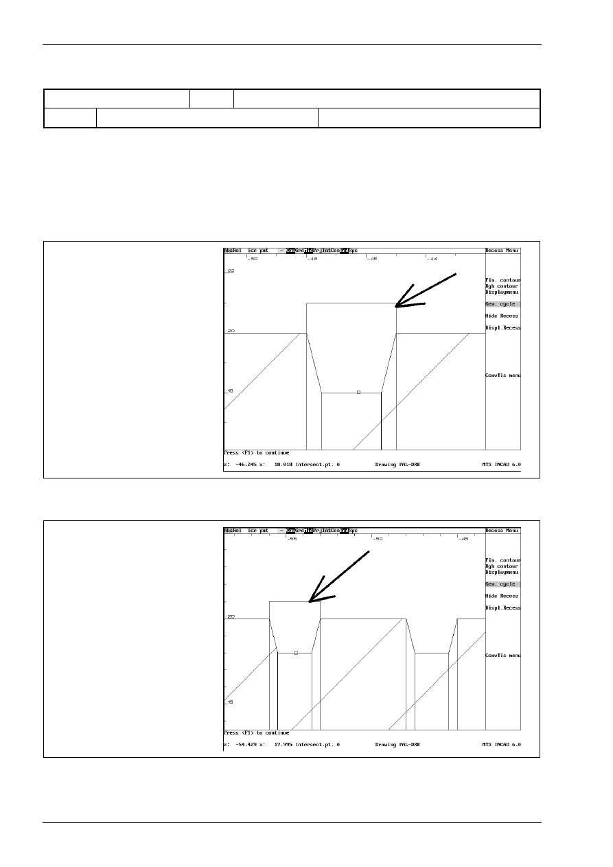
CAD/CAM Turning
202
MTS TeachWare • CADCAM • Student’s Book
tool selection
In the work plan and the set-up sheet the following machining sequence and tool are described.
recessing
T06
external recessing tool
T06
external recessing tool
ER-SGTFL-1212/L/01.8-0 ISO30
We select with the cursor the sixth position, so that its frame is marked then. Go back to the turn menu by
confirming with <F8>.
In the following dialog you can confirm all answers with <Enter> or change if desired the value with the
keyboard. In our example we confirm all.
Coolant M08
Feed(mm/rev): 0.05
m/min: 300
Speed lim. 3500
Move to the tool changing point: Y
Approach opt.: 0
ClearDist. 2.00
Allow in Z 0.00
Diam Allow 0.00
confirming the recessing cycle
Press <F1> to continue
Confirm all entries with <F1>. Do the same with the second recess:
confirming the recessing cycle for
the second recess
Press <F1> to continue
Confirm all entries with <F1>. Leave this menu with the menupoint „ConvTls menu“
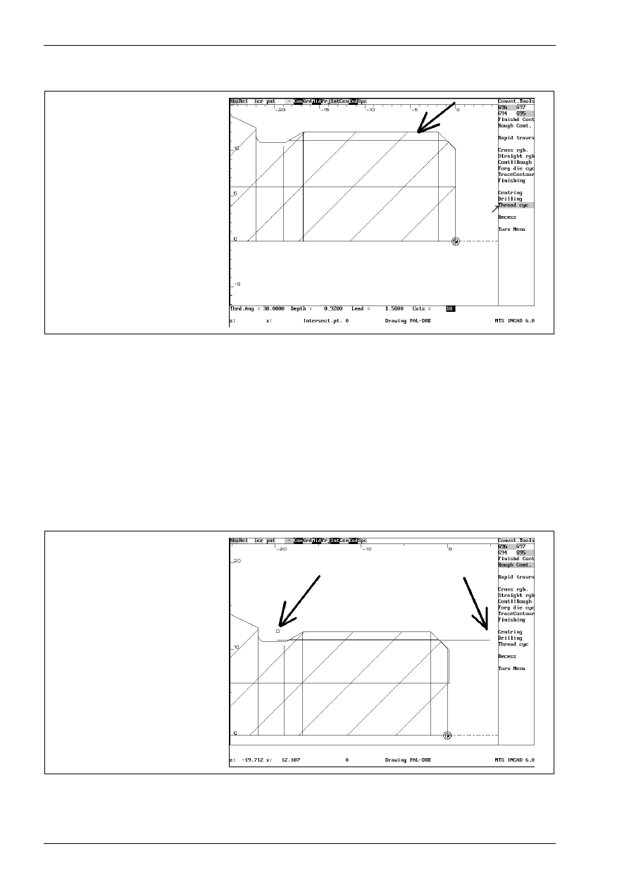
CAD/CAM Turning
204
MTS TeachWare • CADCAM • Student’s Book
defining outer diameter of threading and threading geometry
The system asks for the threading surface. Click on the following entity with the mouse.
selecting the threading surface
Enter the following values in this dialog:
Thrd.Ang = 30
Depth = 0.92
Lead = 1.5
Cuts = 10
Then the system asks for the start and the end point of the threading cycle.
Enter first point of cycle
Click with the mouse in the right of the thread and confirm the following prompt with <Enter>
Allowance in Z: 0.0
Enter second point of cycle
Click with the mouse in the left of the thread and confirm the following prompt with <Enter>
Allowance in Z: 0.0
identifying first and second point
of the thread
Leave this menu with the menupoint „Turn Menu“.
Then you can simulate or save this NC-program in the same way as in CAD-CAM-milling!
Wyszukiwarka
Podobne podstrony:
OSIE DODATKOWE, obrabiarki sterowane numerycznie CNC, kurs MTS CNC
MTS CNC Programowanie CNC Toczenie wydawnictwo REA PL
MTS CNC Programowanie CNC Toczenie wydawnictwo REA PL
MTS Wprowadzenie do symulatora frezowania CNC
cnc w 3 budowa obrabiarek cnc
Projekt ABB, CNC
7---Karta instrukcji obróbki cieplnej, OPERATOR CNC, TECHNOLOG CNC, KARTY TECHNOLOGICZNE
11 Operacje, CNC, wycinanie
CNC
Badanie dokładności geometrycznej obrabiarki CNC FV 580A z zastosowaniem testu QC10
CNC DROGOSZ 1
sciaga CNC duża
ver 10 rozkad urzadzenia i systemy wytw cnc
Generating CNC Code with Edgeca Nieznany
10 Obrobka na tokarce CNC 0
cnc 1 v1 0 pl H56LQWVAJFQUA7XLCRGXFM7R4CYBGMWS2CEF3RY
więcej podobnych podstron