
LOKALNE SIECI
KOMPUTEROWE

Standard FDDI
jako protokół dostępu
do medium światłowodowego
w szkieletowej sieci pierścieniowej
Technologies
for LAN and MAN
(ISO)
FDDI
802.3 802.4 802.5
FDDI
802.2 Logical Link Control
ISO 8802.2
802.6
NETWORK
DATA LINK
PHYSICAL
LLC
MAC
CSMA/CD TOKEN
BUS
TOKEN
RING
DQDB
ISO
8802
.3
ISO
8802
.4
ISO
8802
.5
ISO
8802
.6
ISO
9314

FDDI (Fiber Distributed Data Interface)
Standard processed by:
- ANSI (ANSI X3T9.5)
- ISO (ISO 9314)
Standard specify ring architecture with fibre optical medium.
Characteristic:
ring topology with double loop
throughtput 100 Mbps
optical fibre medium ( 200 km - single-mode fibre),
= 1300 nm,
coding – 4B/5B,
number station - max. 1000.

FDDI is an ANSI (American National Standards Institute) standard
Initial proposals for MAC and PHY (June 1983)
- February 1986 MAC (Rev. 10)
- August 1985 PHY (Rev. 11), problem with specification of elasticity buffer discovered
- August 1987 PHY (Rev. 15)
- June 1988 PMD (Rev. 8)
ANSI X3.139-1987 FDDI Token Ring Media Access Control (MAC)
ANSI X3.148-1988 FDDI Token Ring Physical Layer Protocol (PHY)
ANSI X3.184-1993 FDDI Single-Mode Fiber Physical Layer Medium Dependent (SMF-PMD)
ANSI X3.231-1994 FDDI Token Ring Physical Layer Protocol (PHY-2)
ANSI X3.239-1994 FDDI Token Ring Media Access Control-2 (MAC-2)
ANSI X3.229-1994 FDDI Station Management (SMT)
FDDI - History
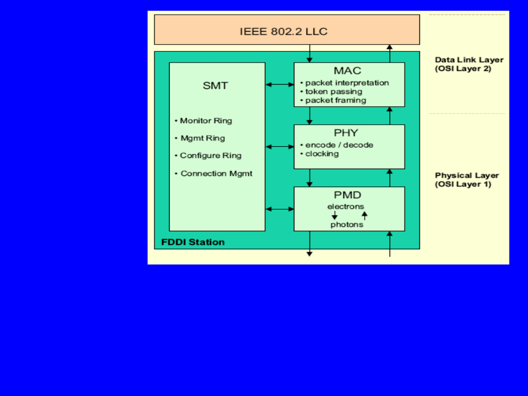
ANSI X3T9.5 defines four mayor sections:
– Physical Medium Dependent (PMD) specifies optical fibre link
and related optical components
– Physical Layer Protocol (PHY) specifies the encode/decode,
clocking, and data framing
– Media Access Control (MAC) defines the access to the medium,
addressing,
data checking, and frame generation/reception
– Station Management (SMT) specifies FDDI station configurations,
ring configurations,
and control for proper ring operations (Network Management
Concept)
FDDI RM
FDDI station architecture

FDDI is based on IEEE 802.5 Token
Ring
– FDDI adopts as much of 802.5 as
possible
– FDDI makes changes where necessary
optical fiber
100 Mbps
NRZI-4B/5B code
explicit reliability
specification
distributed clocking
timed token rotation
new token after transmit
FDDI frame structure
4500-octet maximum
frame size
16- and/or 48-bit addresses
distributed recovery
shielded twisted pair
1 and 4 Mbps
differential Manchester code
no explicit reliability specification
centralized clocking
priority and reservation bits
new token after frame receive
802.5 frame structure
no maximum frame size
16 or 48 bit addresses
active monitor
FDDI
IEEE 802.5 Token Ring
FDDI Characteristic
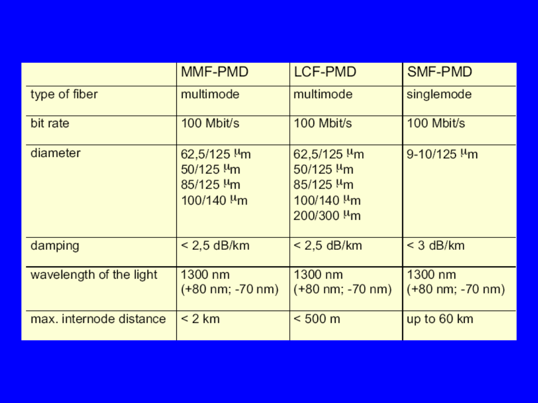
FDDI Optical Fiber Characteristics
•
Two contra rotating rings with 100 Mbit/s data
rate each:
–
primary ring
used for data transmission
–
secondary ring
is for reliability only
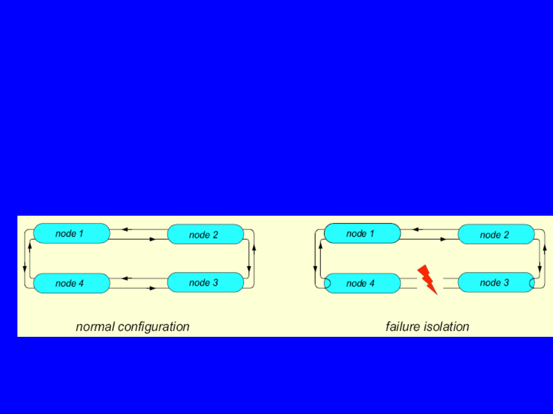
• Nodes can be connected to both rings for
reliability
• In case of link failures, stations reconfigure
using primary
and secondary ring (bypassing of failed link)
FDDI Topology
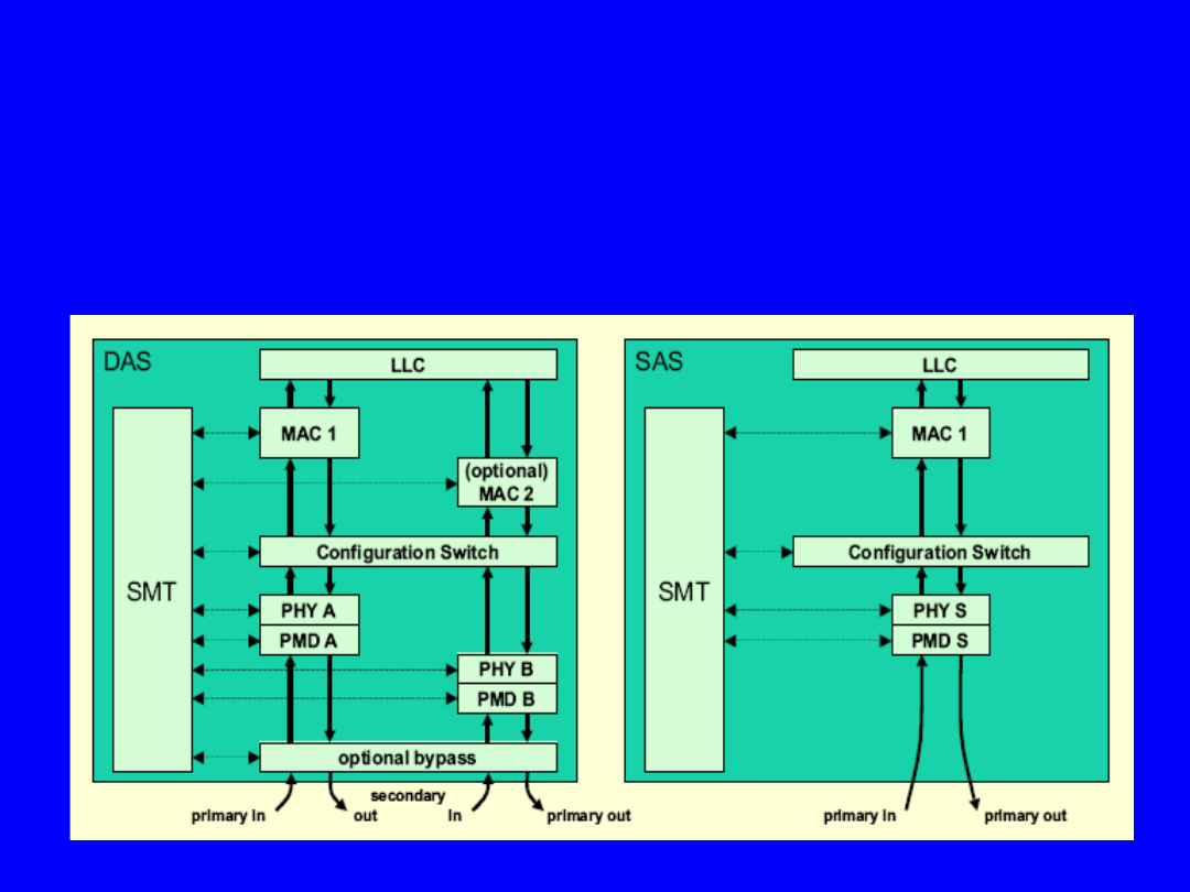
FDDI defines two classes of stations:
– DAS:
Dual-Attachment-Station
(connected to both
rings)
– SAS:
Single-Attachment-Station
(connected only to
the primary ring)
FDDI Station Types
FDDI Station Types
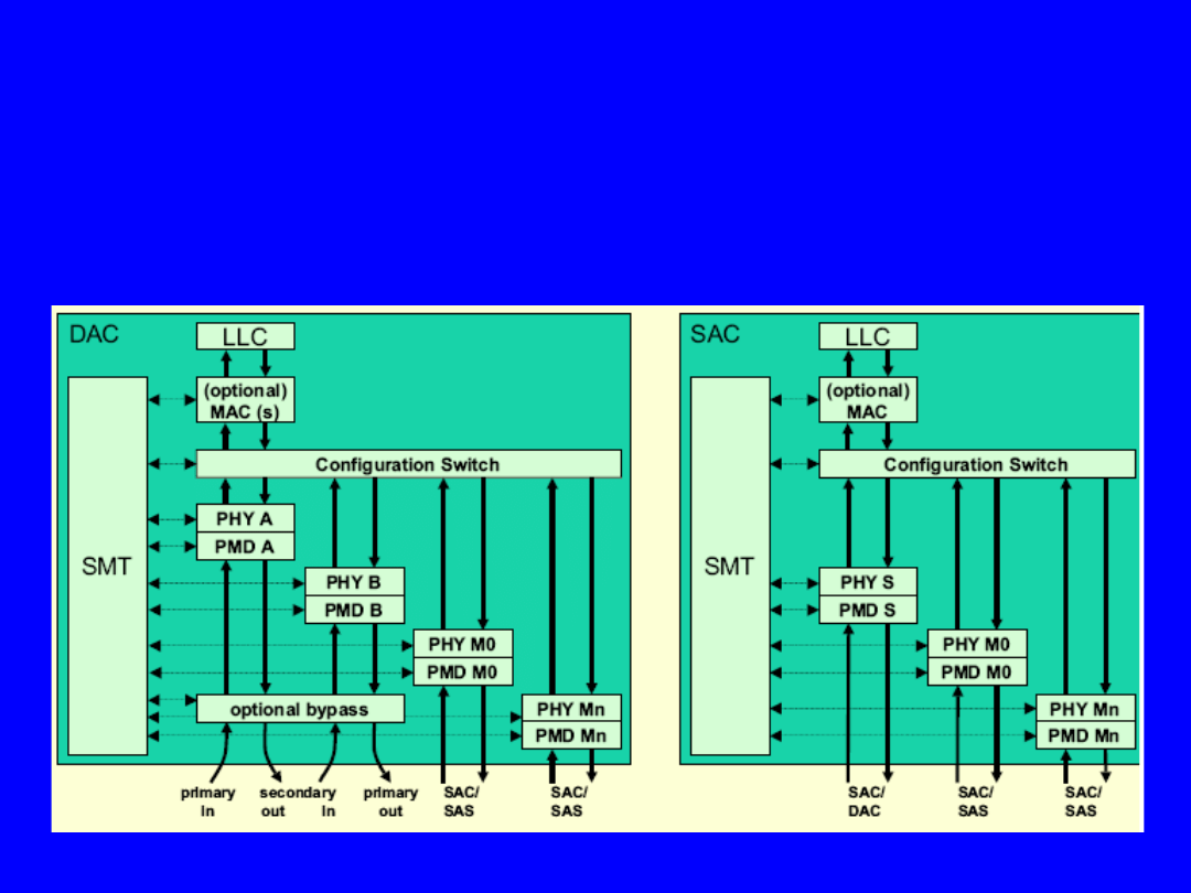
FDDI defines two classes of concentrators:
– DAC:
Dual-Attachment-Concentrator
(connected to both
rings)
– SAC:
Single-Attachment-Concentrator
(connected to DAC
or other SAS)
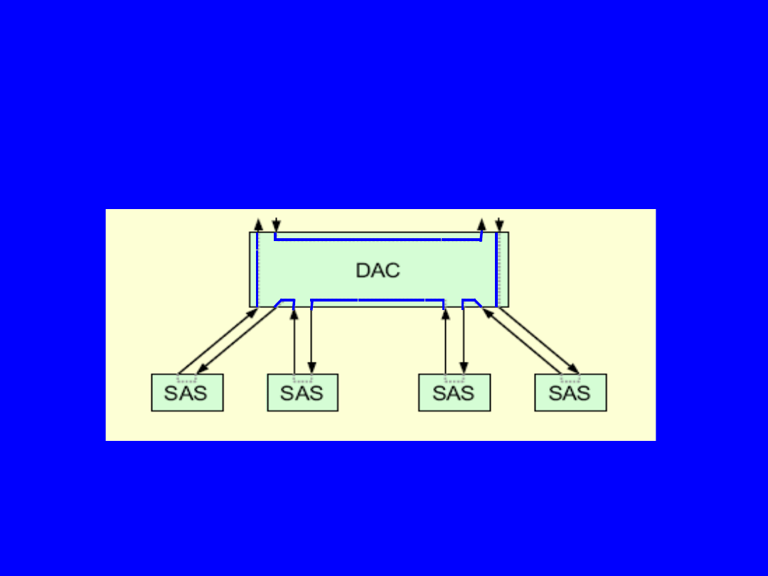
Point-to-Point Topology
Star
Tree Topology
Dual Ring
Dual Ring of Trees
FDDI Network Topologies
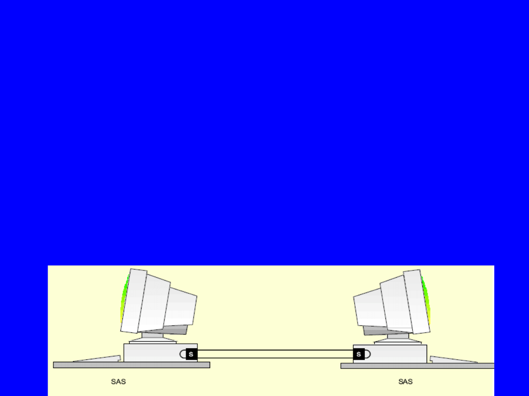
Point-to-Point
– possible between two Single-Attachment-
Stations only
FDDI Network Topologies (cont.)
Star Topology
– only the
primary ring
is used
– failure isolation is
not possible
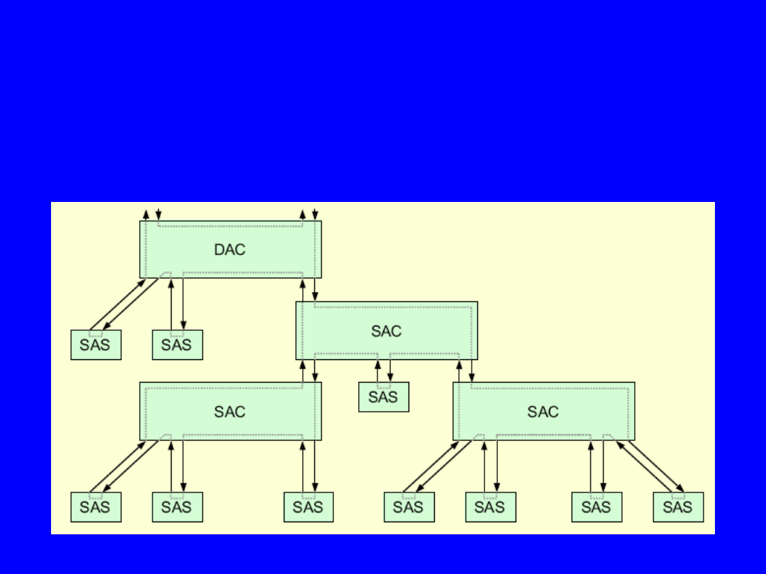
FDDI Network Topologies (cont.)
Tree Topology
– only the
primary ring
is
used
– failure isolation is
not
possible
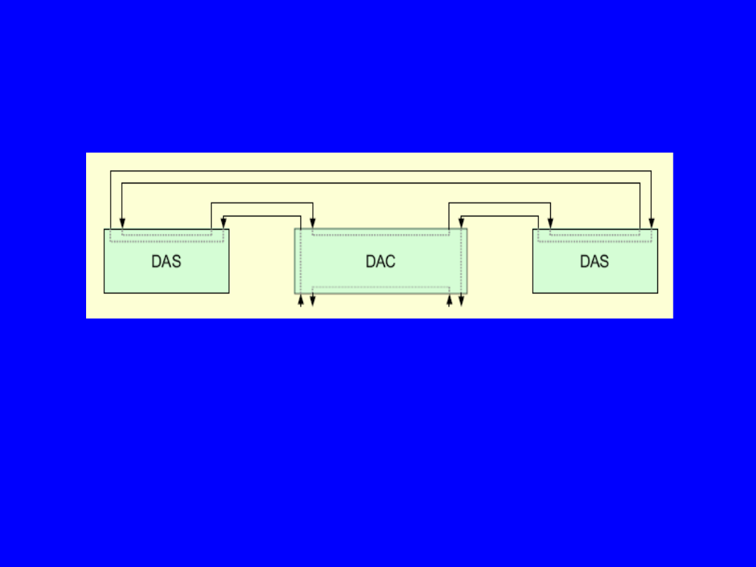
FDDI Network Topologies (cont.)
Dual Ring
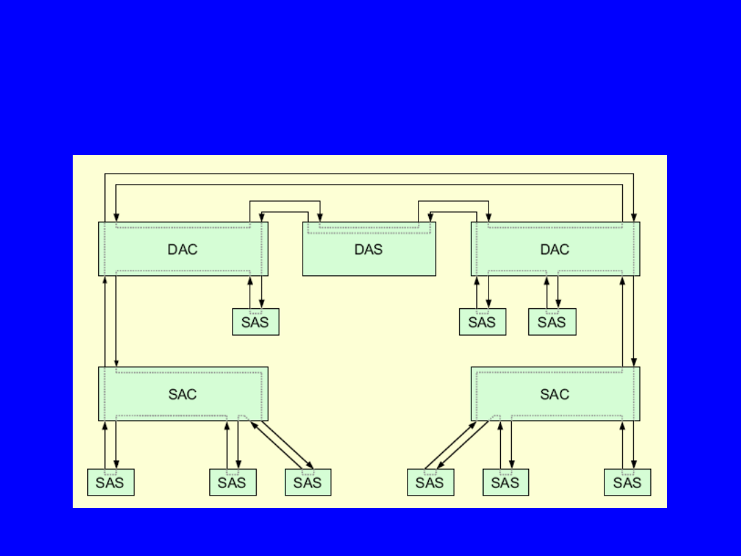
FDDI Network Topologies (cont.)
Dual Ring of Tree
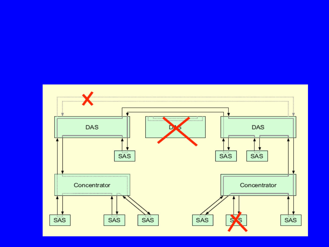
Standard FDDI use enhancing techniques
(dual ring topology, concentrators and station bypass)
to ring reconfiguration in case of link errors or node failures.
FDDI Reliability
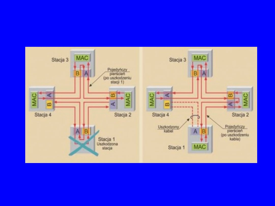
Station or Link Failure
a) Station failure
b) Link failure
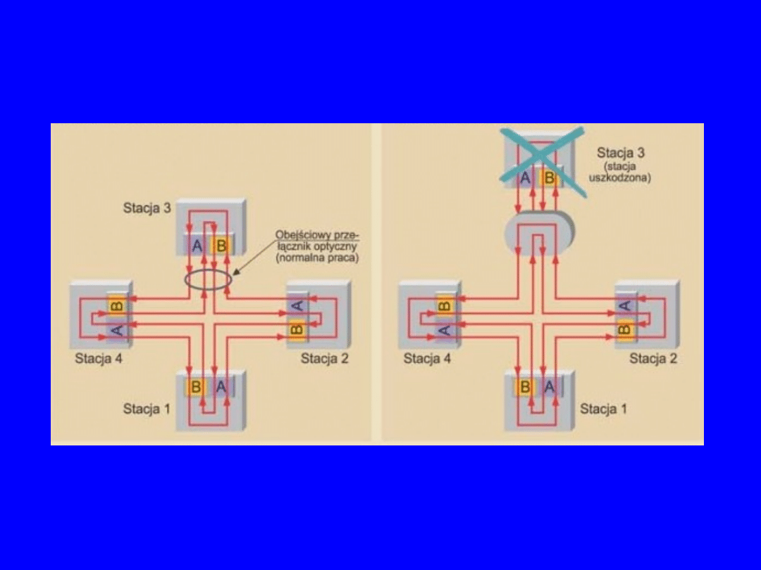
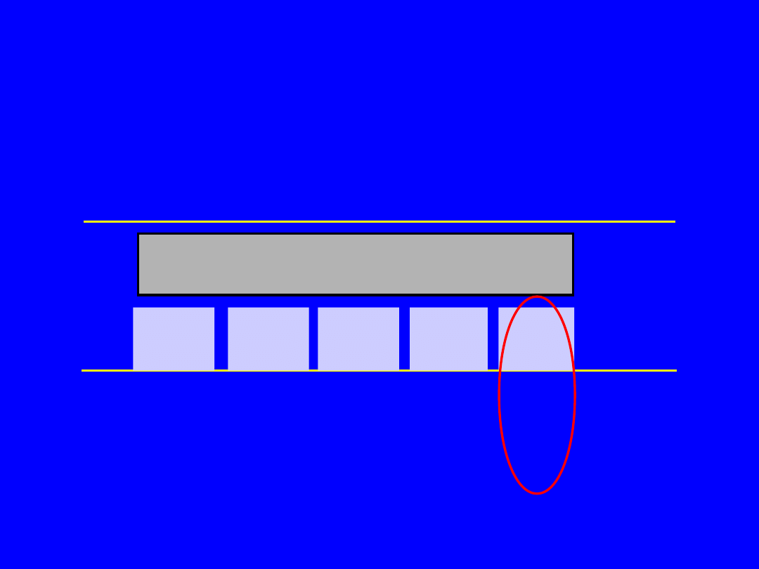
Opitacal bypass station
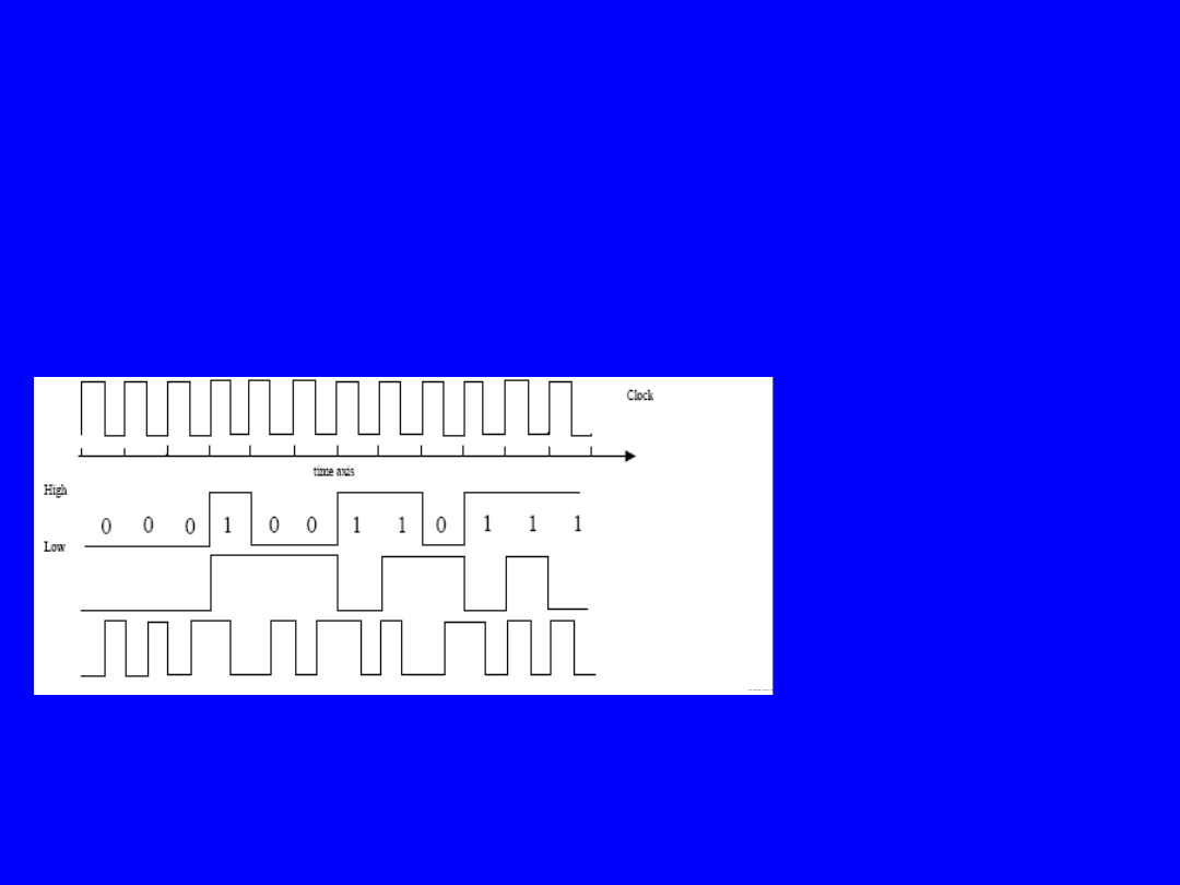
FDDI uses 4b/5b NRZI (Non-Return to Zero Invert)
with 125 Mbps baud rate to achieve 100 Mbps data rate
Ethernet uses Manchester encoding with 20 Mbps baud rate (20 MBd)
to achieve 10 Mbps data rate
FDDI Signal Encoding
NRZ
- used by PC bus (1 = high, 0 = low)
NRZI
- used in combination with 4b/5b
(1 = transition, 0 = no transition)
Manchester
- used by Ethernet
(1 = high-low transition,
0 = low-high transition)
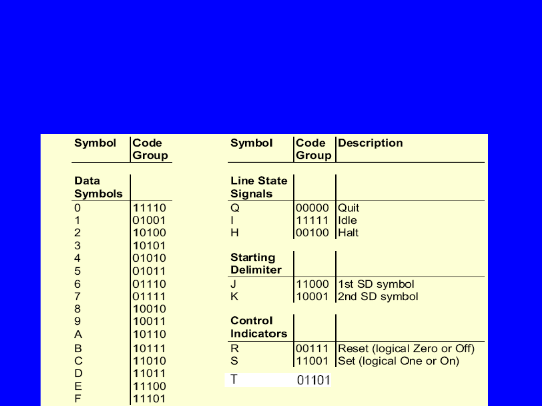
• FDDI uses NRZI - 4B/5B line code
• 4B/5B = 4 bits are encoded as 5 bit pattern (as
symbols)
• Bandwidth efficiency of this code is 80 %
• 100 Mbitps data rate is achieved by a signalling
rate of 125 Mbaud
• 16 data symbols and 8 control symbols
FDDI Data Encoding
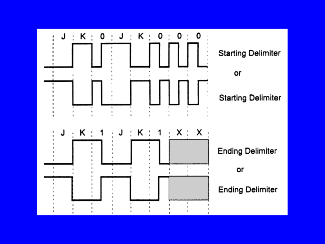
Starting and ending delimiter patterns

FDDI uses a distributed clocking scheme:
• Each station has its own autonomous transmit clock:
– frequency variance between clocks: 0,01 % → 4,5 bits
– frequency accuracy: ± 0,0005 %
• Each station has an Elasticity Buffer (EB) for
compensating clock differences receive and transmit
clock:
– data is clocked into the EB at the incoming clock rate
– data is clocked out the EB at the stations own clock
rate
– EB is similar to FIFO memory
– minimum EB elasticity is 4,5 bits
• IDLE symbols between frames (preamble) are used for
synchronisation
– remove IDLE symbols if incoming clock is faster
– add IDLE symbols if incoming clock is slowe
• Smoothing function removes/adds IDLE symbols from/to
the preamble longer/ shorter than 14 IDLE symbols
FDDI Clocking
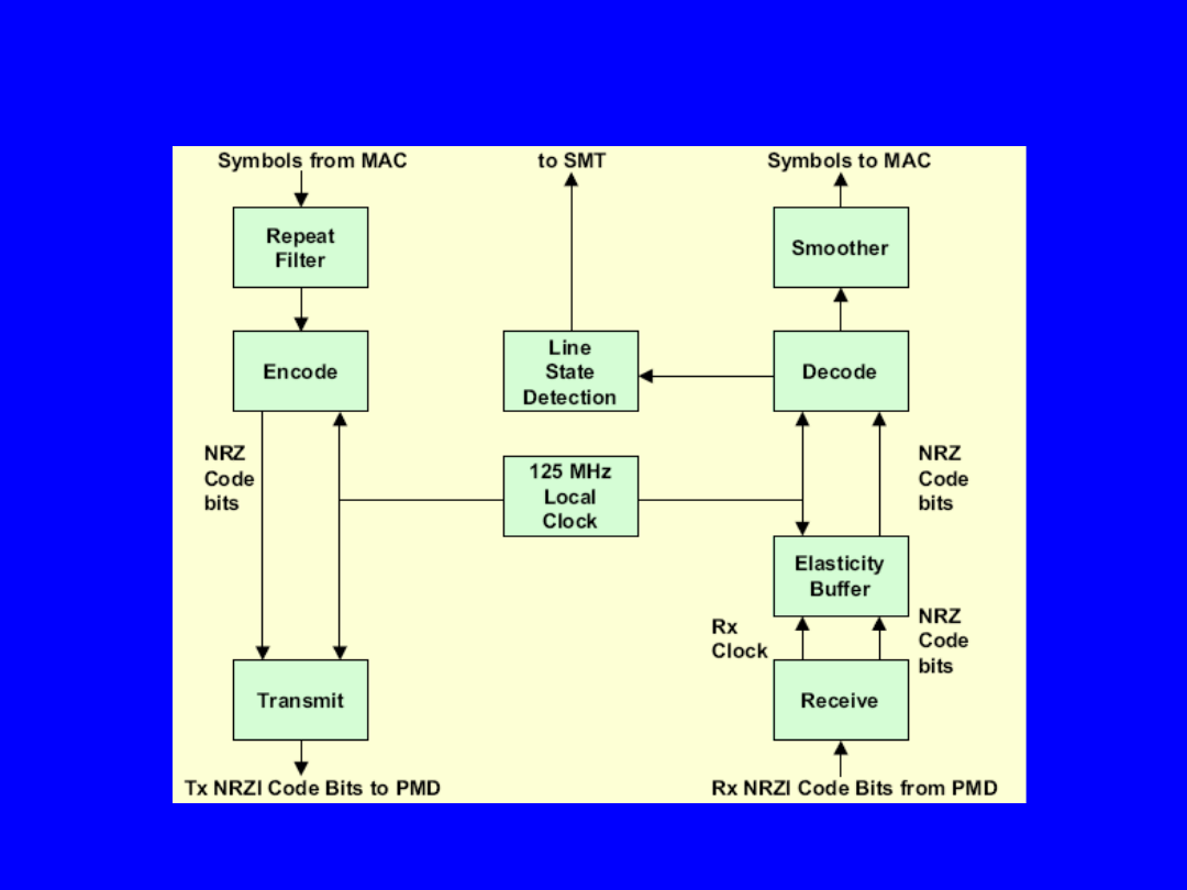
FDDI Clocking (cont.)

Two frame formats are used by
MAC
– Token
– Frame
FDDI MAC Frame Format
PA: 16 or more IDLE symbols for frame
synchronisation
SD: Start Delimiter (2 symbols “JK”)
FC: Frame Control (2 symbols)
ED: End Delimiter (2 symbols “TT”)
FDDI Token
> 16
2
2
2
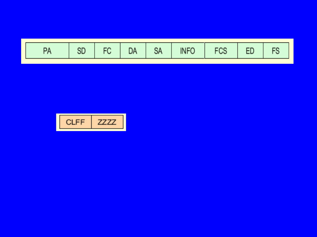
FDDI MAC Frame Format (cont.)
FDDI Frame
PA: 16 or more IDLE symbols for frame synchronisation
SD: Start Delimiter (2 symbols “JK”)
FC: Frame Control (2 symbols)
C = class bit (0=asynchronous frame, 1=synchronous frame)
L = address length bit (0=16 bit, 1=48 bit)
FF = format bits (LLC or MAC control frame)
ZZZZ = control bits (type of frame control)
DA: 16 or 48 bit Destination Address
SA: 16 or 48 bit Source Address
FCS: Frame Check Sequence (32 bit CRC)
ED: End Delimiter (1 symbol “T”)
FS: Frame Status (3 or more symbols)
-
error detected (E), address recognized and frame copied indicators
> 16
2
2
1
4/12
4/12
3
9000
8
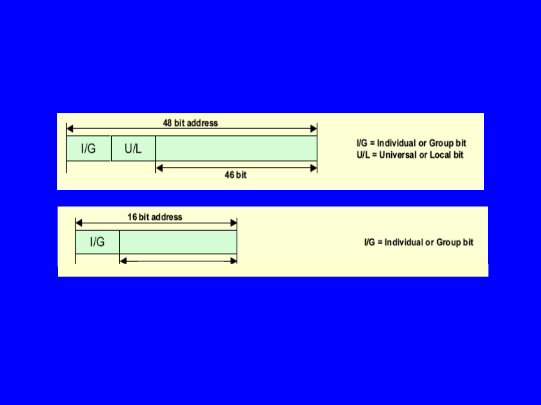
• Point-to-point, multicast, and broadcast capability
• FDDI employs IEEE 802.5 address structure:
FDDI Addressing
15 bits
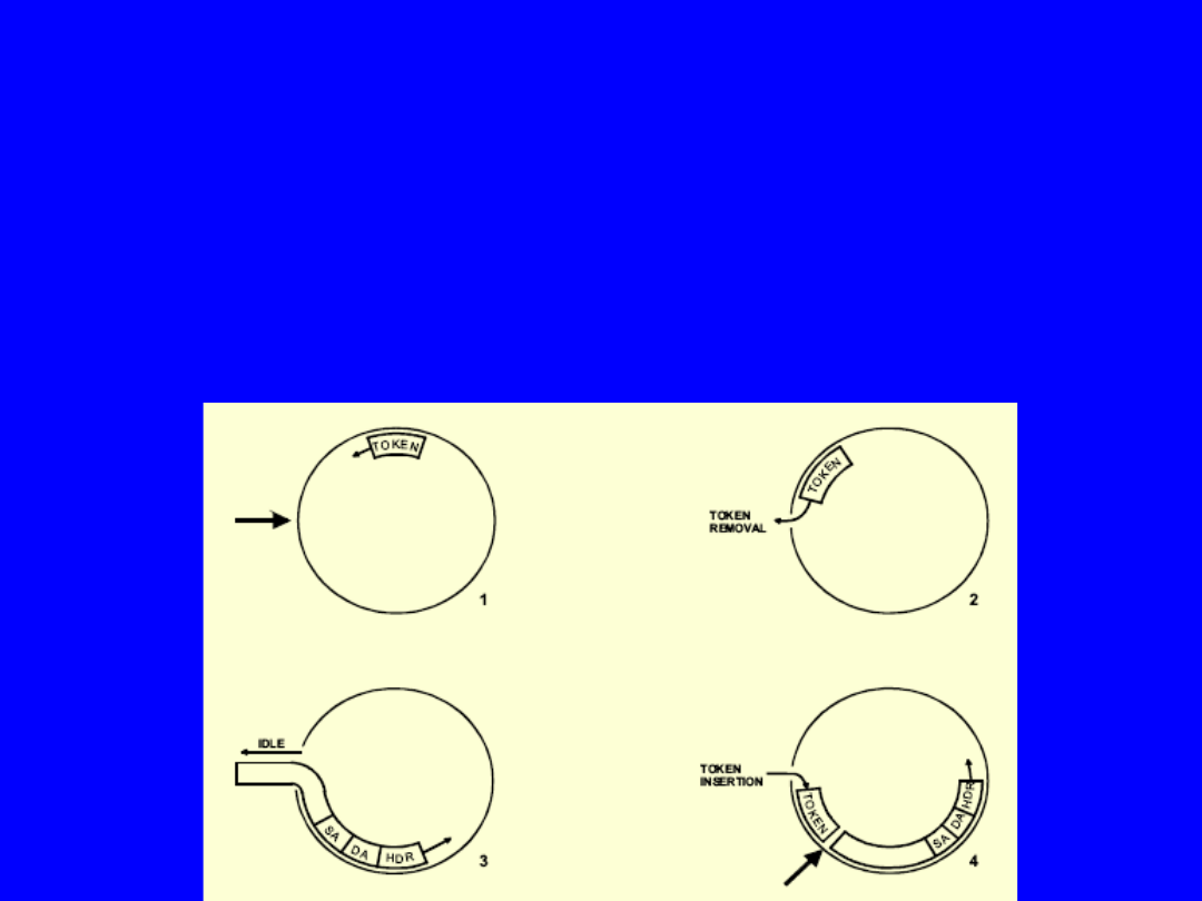
• Station wishing to transmit frames removes token
• Station transmits one or more frames of data
• After transmission station issues a new token
• Transmitted frames are regenerated and repeated
by active stations
• Destination station copies frame(s)
FDDI Token Ring Protocol
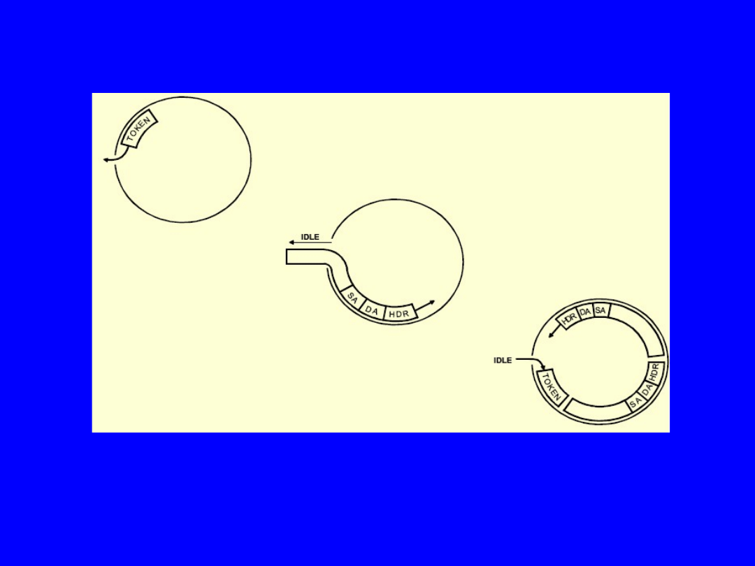
FDDI Token Release on Multiple Frame Transmission

• FDDI uses a Timed Token Rotation Protocol controlling the
access to the medium
• The amount of bandwidth a station can use for data
transmission
is limited by the time of token possession
•
Target Token Rotation Time (TTRT)
– defines the max. value for the circulation time of the token in
the ring
– definition of TTRT at ring initialisation time
– example: TTRT = 50 ms (30 km ring length, 75 stations)
•
Token Rotation Time (TRT)
is measured by each station for each
token circulation
• When the token arrives at the station:
– TRT is saved in the Token Holding Timer (THT)
– TRT is set to zero and starts running again
•
The station may transmit asynchronous data only as long as THT
< TTRT
FDDI Timed Token Rotation Protocol
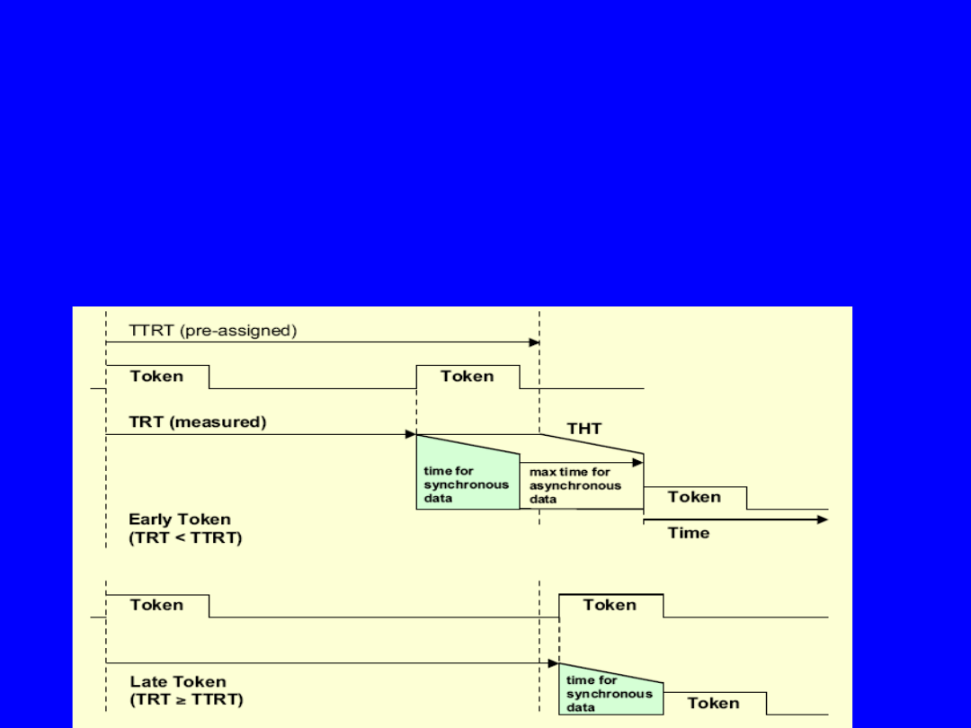
FDDI Timed Token Rotation Protocol
TRT is measure of load:
• IF TRT < TTRT (early token)
→
little load
, station can send
synchronous and
asynchronous data
• IF TRT > TTRT (late token)
→
heavy load,
station can only send
synchronous
data
• Average TRT value is on the order of TTRT or less
• Maximum TRT value is 2 x TTRT

• Ring monitoring is distributed among all stations in the ring
• High value of TRT (> 2 x TTRT) is an indicator for errors
• Three processes are involved in initialisation and recovery:
– Beacon Process
– Claim Token Process
– Initialisation Process
Beacon Process:
• This process is used to isolate ring failures
• Each station sends beacon frames
• A station receiving beacon frames from an other station stops
issuing own frames
and forwards the received beacon frames
• The station receiving its own beacon frames initiates the claim
token process
Claim Token Process:
• This process is used to negotiate the TTRT value and to resolve
contention among
the stations for ring initialisation
• Each station generates a claim frame containing a TTRT bid
• A station stops generating claim frames when receiving a lower
TTRT bid
and forwards the other frames
• The MAC with the lowest TTRT bid that had the highest address
will win the process
Initialisation Process:
• The station which won the CLT is responsible for the initialisation
of the ring
FDDI Ring Initialisation and Recovery
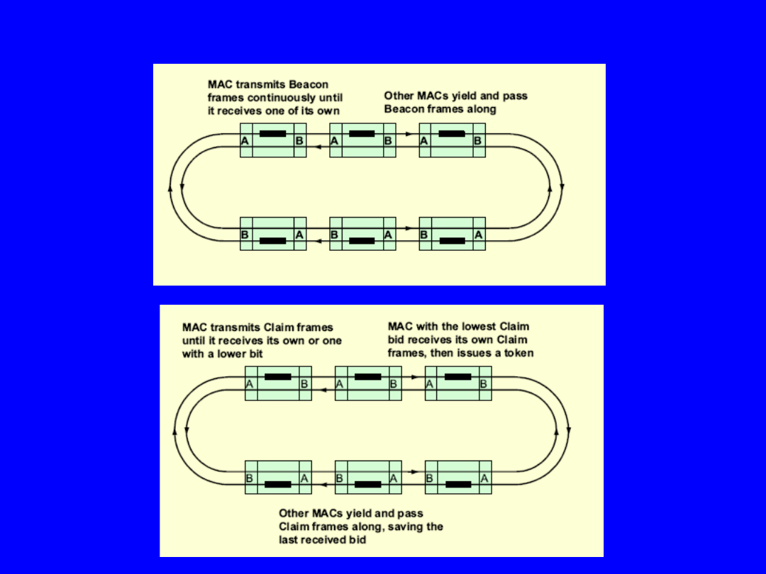
FDDI Ring Initialisation and Recovery (cont.)

FDDI Station Management (SMT)
SMT provides FDDI specific network management
Each FDDI station has one SMT entity
SMT contains three parts:
1. Connection Management (CMT)
• Establishing and maintaining the physical and logical
topology of the ring
• Manages PHY components and their interconnections
• Manages configuration of MAC/PHY entities
• Link error monitoring
2. Ring Management (RMT
)
• Establishing and maintaining the correct logical ring
operation (usable token)
• Managing if MAC layer resources of a FDDI station
3. Operational Management
• Management of the FDDI network in the operational
state
• OSI layer management protocol
• Obtain and modify management attributes by
management agents
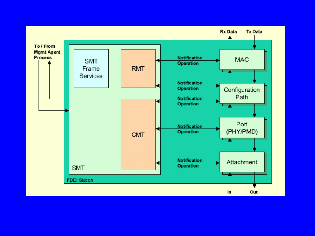
FDDI Station Management (SMT)
Connection Management (CMT)
Ring Management (RMT)
Operational Management
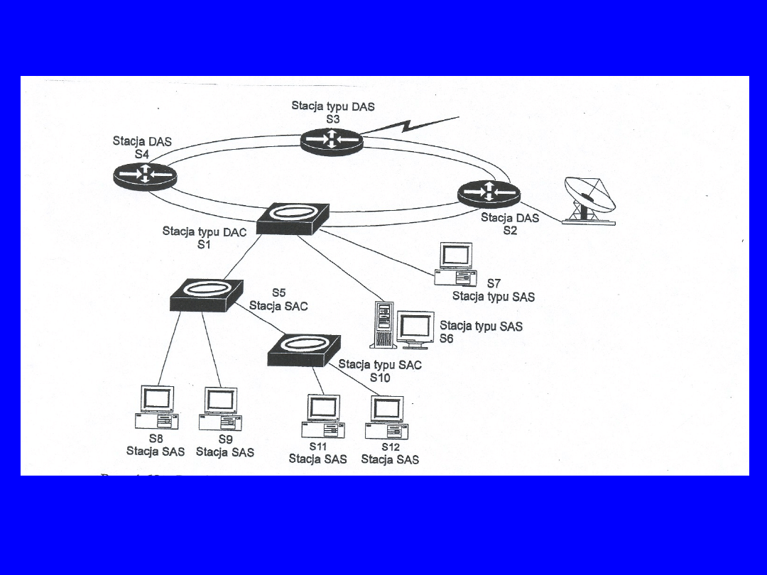
Architektura sieci FDDI -
przykład

• FDDI efficiency problem token propagation time
• With increasing speed and increasing station distances
FDDI becomes less efficient
• Throughput versus access delay
• TTRT is an important factor
• FDDI throughput = (TTRT - Ring Latency) / TTRT
– ring latency = 0,25 ms (30 km ring length with 75
stations)
– TTRT = 50 ms → Utilisation = 99,5 %
• FDDI access delay is less then 2 x TTRT
FDDI Efficiency

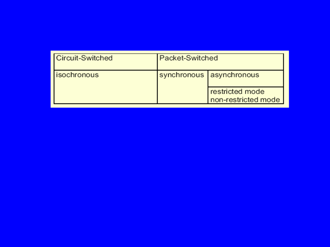
FDDI - II (Fiber Distributed Data Interface ver. II)
Extension FDDI standard
- asynchronous/synchronous +
isochronous services
Protocol
– type Slotted Ring
Multiframe (every 125 s)
- 16 channels type WBC (ang. Wide Band Channel) with 6,144 Mbps
Frame organisation:
Preamble + header (116 bits)
0,928 Mbps
N isochronous channels (N*768 bits)
N x 6,144 Mbps
Asynchr./synchr. Transmission (96 +(16-N)*768 bits) 0,768 + (16 -N) x 6,144 Mbps
Data bandwith in FDDI II:
8 / 16 / 32 kbps - voice or data
64 kbps
- channel type B ISDN
384 kbps
- 6 channels type B = channel H0 ISDN
1536 kbps
- 24 channels type B = channel H11 ISDN
1920 kbps
- 30 channels type B = channel H12 ISDN
1544 / 20468 kbps
- system T1 / E1
6144 kbps
- WBC channel
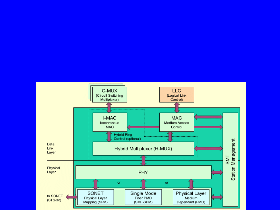
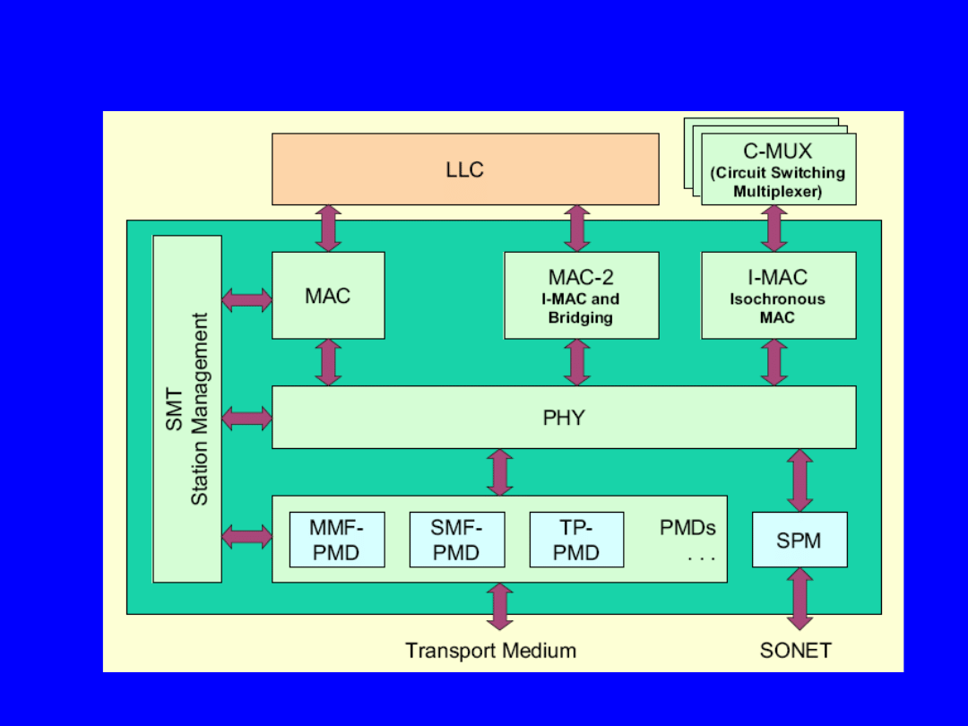
• FDDI-II requires an additional standard between PHY and
MAC
called Hybrid Ring Control (HRC) sublayer
• HRC defines two additional entities to support isochronous
data transmission
– Hybrid Multiplexer (H-MUX)
– Isochronous MAC (I-MAC)
• HRC multiplexes data between the Packet MAC
and the new Isochronous MAC (I-MAC) used for FDDI-II
FDDI - II Standard
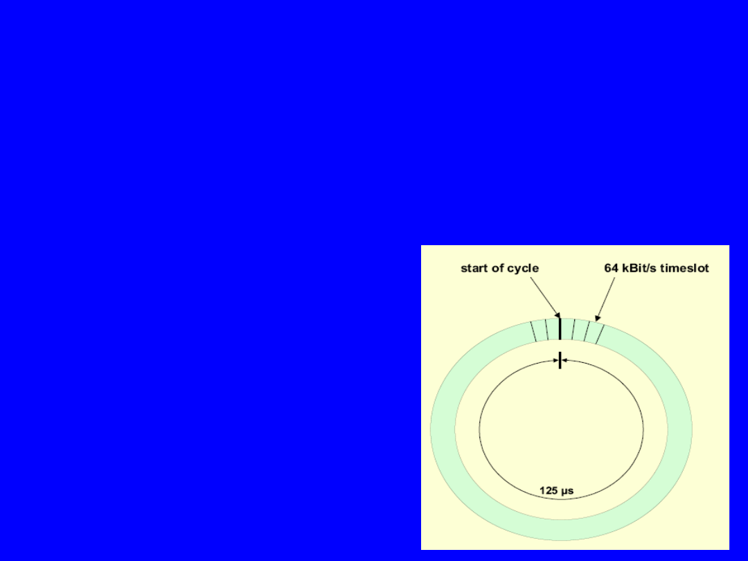
•
Additional one station functions as Cycle Master (CM)
• CM generates a cycle structure every 125 μs on to
ring (slotted ring)
• Cycle comprises fixed number of timeslots
• Each cycle consists of:
– minimum packet data channel of 768 kbps
– 16 Wideband Channels (WBCs) each of 6,144 Mbps
→ total bandwidth of 98 304 Mbps
• Total bandwidth will be shared between CS and PS
FDDI-II - Operation
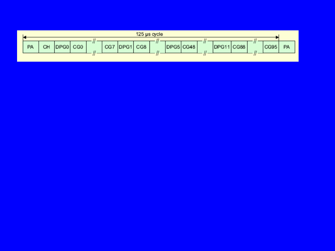
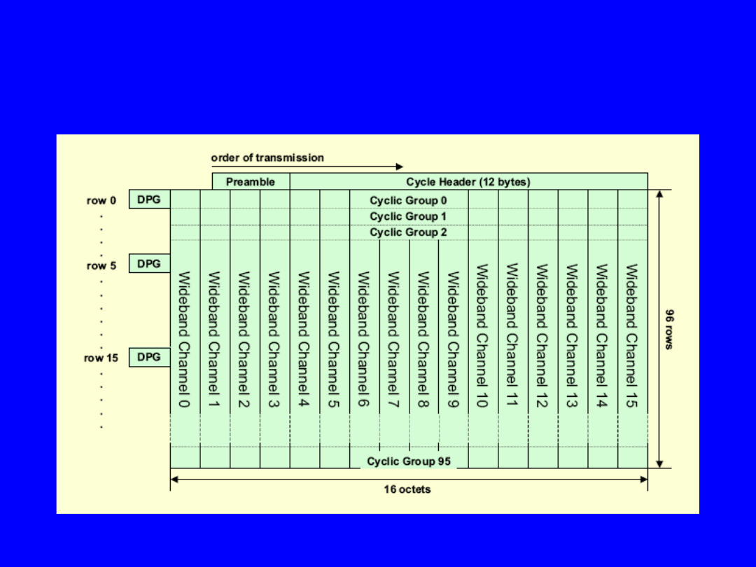
Cycle structure consists of 4 parts:
• PA – Preamble (5 symbols for cycle synchronisation)
• CH - Cycle Header (24 symbols for cycle management)
• DPG0 - DPG11 - Dedicated Data Packet Group:
– 12 bytes minimum guaranteed packet data bandwidth
(=768 kbps)
– byte interleaved among cyclic group
• CCG0 - CG95 - Cyclic Groups:
– 96 cyclic groups of 16 bytes each
– each byte in a CG represents one dedicated WBC
– 96 CGs = 96 bytes * 8000 1/s = 6,144 Mbps
FDDI-II - Cycle Structure
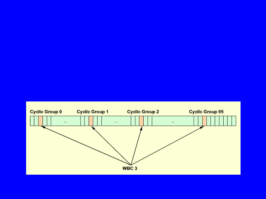
• 16 wideband channels are available
• WBC bandwidth is 6,144 Mbps
• bandwidth of a WBC can be divided into subchannels of 8,
16, 32 or 64 kbps,
plus any multiples of 64 kbps
• 1 WBC = 3 * 2,048 Mbps or 4 * 1,535 Mbps (DS1)
• WBCs are byte interleaved across 96 cyclic groups
• WBC “n” comprises the nth byte from each cyclic group
FDDI-II - Wideband Channels
FDDI-II - Wideband Channels (cont.)
• FDDI-II bandwidth is shred between
CS and PS
• Dynamic CS bandwidth allocation via
SMT
FDDI-II - Operation
Packet switching
• PS bandwidth = total bandwidth - CS bandwidth
• WBCs not used for CS are available for PS
• Minimum PS bandwidth = DPG
• MAC frames will be distributed on cycles by H-MUX
Circuit switching
• Negotiation of maximum CS bandwidth at ring initialisation
• Dynamically allocation of WBCs or subchannels via packet
channel (SMT)
at cycle master (captures token for interrupting PS, releases
token, etc.)
• Each WBC or subchannel represents a dedicated position in the
cyclic structure
• Subchannel consists of a fixed number of adjacent bits of one
WBC
Example: 64 kbps is one byte of a WBC

Document Outline
- Slide 1
- Slide 2
- Slide 3
- Slide 4
- Slide 5
- Slide 6
- Slide 7
- Slide 8
- Slide 9
- Slide 10
- Slide 11
- Slide 12
- Slide 13
- Slide 14
- Slide 15
- Slide 16
- Slide 17
- Slide 18
- Slide 19
- Slide 20
- Slide 21
- Slide 22
- Slide 23
- Slide 24
- Slide 25
- Slide 26
- Slide 27
- Slide 28
- Slide 29
- Slide 30
- Slide 31
- Slide 32
- Slide 33
- Slide 34
- Slide 35
- Slide 36
- Slide 37
- Slide 38
- Slide 39
- Slide 40
- Slide 41
- Slide 42
- Slide 43
- Slide 44
- Slide 45
- Slide 46
Wyszukiwarka
Podobne podstrony:
Wykład 3a 3aGiełdy w Polsce
3a prerequisiti PL
Wykład och zao 3a
s9 3a v1
cwiczenie 3a
OSCR 3a
2 3a Uklad tolerancji i pasowan ISO (2)
5 2 3a CCNA1 Laboratorium pl id Nieznany (2)
SPRAWKO LSK
3A
Language Test 3A
3a
ekol'3a
lab 11 2 3a
Anamnesis59 3a str 36 37
3a wz6
plan pracy-działanie dr lsk na punkcie lsk, wojskowe, Chemiczne
KOLOKWIUM 3a Biologi1, UW Ochrona Środowiska Biologia Biotechnologia, chemia organiczna, chemia orga
więcej podobnych podstron