
April 2004
Budi Juswardy
1
V80 Camera
Test & Troubleshooting
Training
Budi Juswardy
Singapore Design Centre - MIC Level
3
Personal Communication Sector,
Motorola
DID: (65) 6486-2761
Fax: (65) 6482-3841
E-mail:

April 2004
Budi Juswardy
2
V80 Camera
Test

April 2004
Budi Juswardy
3
V80 Camera Test
for
High Volume Mass Production
• DLI TEST
– Data Line Integrity Test (DLI)
– To verify none of the parallel camera data bus lines are
stuck high or low
– To verify none of the parallel camera data bus lines are
shorted together
• Blemish, Noise Line Test
– Blemish Test: Used to detect foreign material or defective
pixels
– Noise Line Test: Used to detect whether there is noise/
lines in the image produced by the camera sensor

April 2004
Budi Juswardy
4
V80 Camera Test
DLI Test
• This built-in test pattern is generated by a “sum of
coordinates” algorithm
• Implemented by combinational logic circuitry in some
imager modules
• DLI Test Algorithm:
– Monitor parallel camera data bus values from test image
– Verify each data bit is low at some point
– Verify each data bit is high at some point
– Verify every possible data bit pair (D0:D1, D0:D2, etc.) is
different (one high & one low) at some point
– Verify every possible data bit pair (D0:D1, D0:D2, etc.) is
not the same during the data analysis for not longer than
90% of the analyzed data. (% can be set)
April 2004
Budi Juswardy
5
• Test will generate a file with the test result/
information
• The format:
• Pass
: 00; Fail: 01
• Matrix
: will compare one line to another line
• High Line
: will pull the line all to high, if pass
will show FF, otherwise it will indicate where
the line shorted to ground
• Low Line
: will pull the line all to low, if pass, will
show FF, otherwise it will indicated where the
line is shorted to Vcc
V80 Camera Test
DLI Test
xx/xx/xx/xx
Low Line
High Line
Matrix
PASS/ FAIL
April 2004
Budi Juswardy
6
V80 Camera Test
DLI Test
•Test Algorithm Detail for 8-bit Bus
Verify each of the following conditions pass for an overall pass
(success) test result
•
D0 = high
•
D1 = high
•
D2 = high
•
D3 = high
•
D4 = high
•
D5 = high
•
D6 = high
•
D7 = high
•
D2 <> D3
•
D2 <> D4
•
D2 <> D5
•
D2 <> D6
•
D2 <> D7
•
D3 <> D4
•
D3 <> D5
•
D3 <> D6
•
D3 <> D7
•
D4 <> D5
•
D4 <> D6
•
D4 <> D7
•
D5 <> D6
•
D5 <> D7
•
D6 <> D7
•
D0 = low
•
D1 = low
•
D2 = low
•
D3 = low
•
D4 = low
•
D5 = low
•
D6 = low
•
D7 = low
•
D0 <> D1
•
D0 <> D2
•
D0 <> D3
•
D0 <> D4
•
D0 <> D5
•
D0 <> D6
•
D0 <> D7
•
D1 <> D2
•
D1 <> D3
•
D1 <> D4
•
D1 <> D5
•
D1 <> D6
•
D1 <> D7
xx
/
xx
/
xx
/
xx
Low Line
High Line
Matrix
(00)
PASS
(01)
FAIL

April 2004
Budi Juswardy
7
V80 Camera Test
DLI Test
• E.g.:
– 00/FF/FF/FF: all pass
– 01/
CF
/FF/FF:
matrix failed
• C
F =
1
D7
1
D6
0
D5
0
D4
1
D3
1
D2
1
D1
1
D0
D4=D5 (shorted)
– 01/FF/
F8
/FF:
high line failed
• F
8
= 1
D7
1
D6
1
D5
1
D4
1
D3
0
D2
0
D1
0
D0
D2=D1=D0 (shorted to gnd)
– 01/FF/FF/
3D
:
low line failed
• 3D
=
0
D7
0
D6
1
D5
1
D4
1
D3
1
D2
0
D1
1
D0
D7=D6=D1 (shorted to Vcc)

April 2004
Budi Juswardy
8
V80 Camera Test
Blemish & Noise Test
• Blemish Test
– Used to detect foreign material or defective pixels
– Due to lens defect/ deformation, dust particle on lens
or the sensor pixel damaged
– (or could be due to the lens cover not removed).
• Noise Line Test
– Used to detect Horizontal Lines in the image
– Horizontal Lines are caused by noisy analog supply
line; OR
– Camera sensor lens defect.

April 2004
Budi Juswardy
9
V80 Camera Test
Blemish & Noise Test
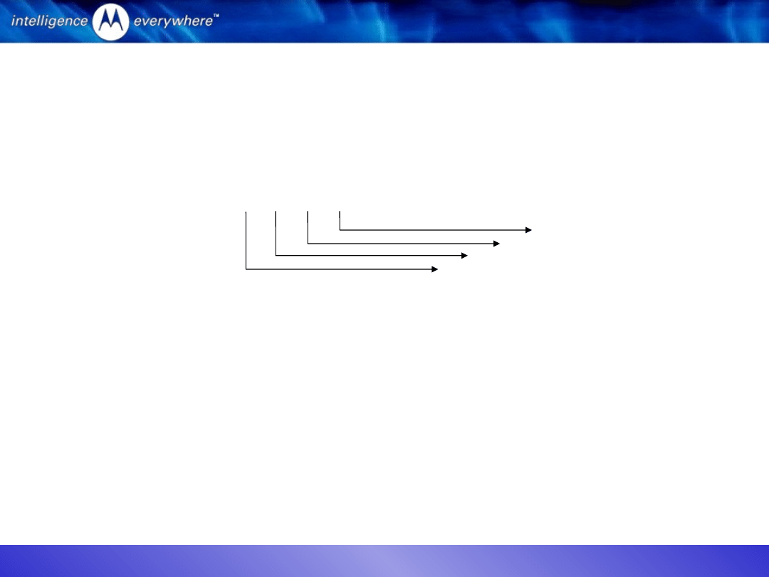
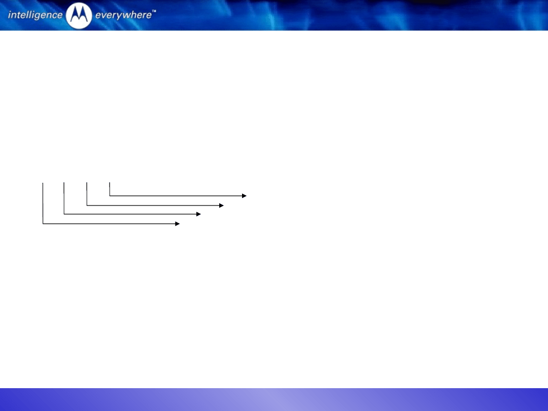
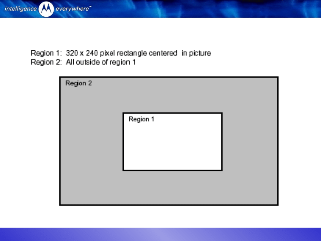
• Requirements for Blemish test:
– NO blemishes
of any size (0x0) is allowed in
Region
1
(R1)
– Not more than 1
of small blemish (1x2) or large
blemish (2x3) is allowed in
Region 2
(R2)
– Fail
if the blemish size is larger than (1x2) size
• Requirement for Noise Line test:
– No horizontal line
noticeable or detectable in the
camera viewfinder
April 2004
Budi Juswardy
10
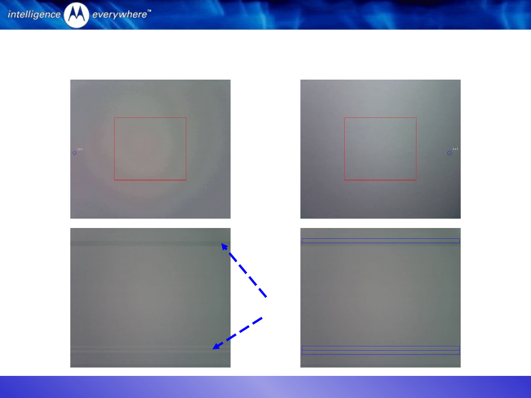
V80 Camera Test
Blemish & Noise Test
April 2004
Budi Juswardy
11
V80 Camera Test
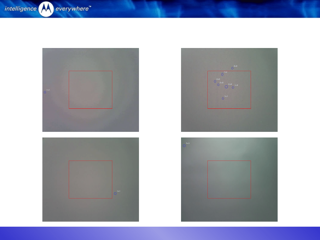
Blemish & Noise Test
Only one 1x1 in
region 2: PASS
Only one 3x1 in
region 2: PASS
Lots of blemishes
in region 1: FAILED
One large 5x3 in
region 2: FAILED
April 2004
Budi Juswardy
12
V80 Camera Test
Blemish & Noise Test
Only one 1x1 in
region 2: PASS
One large 3x3 in
region 2: FAILED
Horizontal Lines
April 2004
Budi Juswardy
13
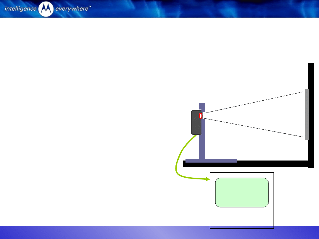
Test Setup
1.
Ambient fluorescent lighting sources
2.
Test Chart at 18 to 25 cm distance
3.
Fixture with open nest to locate and align the
UUT
4.
UUT (V80 Phone with camera facing test chart)
5.
CE-Bus to PC
1
2
3
4
5
Side View Of the Test
Fixture
Test Station PC
Test Flow
1.
UUT powers up, enumerates, and is suspended.
2.
Camera viewfinder opened (TST_CAMERA).
3.
Test chart image captured (TST_CAMERA).
4.
Test command (TST_CAMERA, parameter 0x06)
initiates the Data Line Integrity test.
5.
UUT returns Success or Failure response to Test
Station PC.
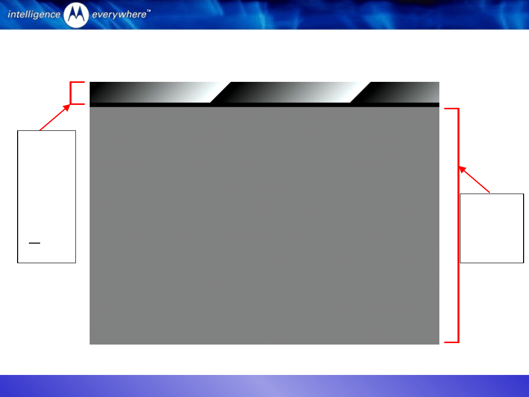
V80 Camera Test
Blemish & Noise Test
April 2004
Budi Juswardy
14
Camera Test Chart
Blemish
& Noise
Test
Area
Data
Line
Integri
ty
Test
Area
(+10%
)

April 2004
Budi Juswardy
15
V80 Camera
Troubleshooting
April 2004
Budi Juswardy
16
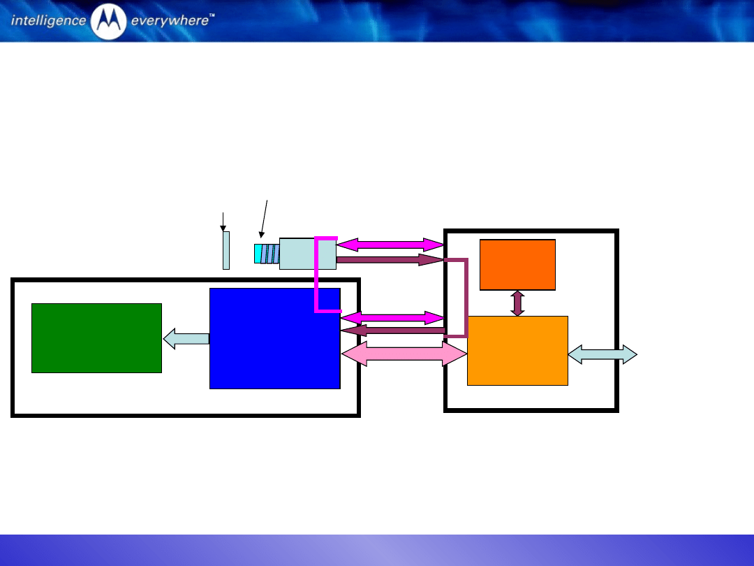
V80 Camera Block Diagram
ATI 2250
Graphics
Accelerator
Baseband
Processor
Serial
VGA
LCD
Display
Control Lines
Data Lines
Image
Sensor
Lens
Cover
Lens
Flash
USB
Test Station PC
via CE Bus
JPEG Encode Only
C-Flex
Front Housing
Blade
Radio
board
PCB

April 2004
Budi Juswardy
17
Camera Test Sequence
•
ENTRY HD2
entry_handler_atlas_CIT_camera
•
GCI1STAT
get_command_interface
Check the CE Bus connector
•
SUS1STAT
suspend_1
Reconnect the CE Bus connector
•
*
backlight_light
•
CAM_EDLI
DLI
Make sure DLI pattern is only 10% on the viewfinder
Check and make sure camera alignment ok
•
DELAY104
Delay1_3_secs
•
CAM_SDLI
DLI
Check the generated error file (slide 5)
•
*
camera_capture_VGA_DLI
•
ECMSTAT
External_camera_image_transfer_status
•
CAM_BLS1
small_blemish_region_1
Check the Blemish image at region 1 (slide 9)
•
CAM_BLL1
large_blemish_region_1
Check the Blemish image at region 1 (slide 9)
•
CAM_BLS2
small_blemish_region_2
Check the Blemish image at region 2 (slide 9)
•
CAM_BLL2
large_blemish_region_2
Check the Blemish image at region 2 (slide 9)
•
CAMBLSTAT
Blemish Test Status
FAIL this section if any of CAM_BL* test fail
Check and make sure camera alignment ok
Remove the lens cover
No dust/ foreign particle or scratch at the lens
•
CAMNUMNL
Camera_no_of_noise_lines
Check the Noise Line image (NL) (slide 12)
•
CAMNLSTA
NL_test_status
FAIL this section if there is Noise Line detected
Check and make sure camera alignment ok
Remove the lens cover
No dust/ foreign particle or scratch at the lens
•
Not available
Not available because log result was not called display in PC.
•
TOF_CMDI
Turn_of
Do not disconnect the USB cable from CE Bus until the test is completed
What to check when camera test fail at
this point.

April 2004
Budi Juswardy
18
Fail DLI Test?
1. Open the backhousing, and check/ make sure the pin-to-pin connector
of camera to the PCB Board is attached properly. RETEST.
2. Replace the camera sensor. RETEST.
Suspect it is either:
a. The B2B pin camera connector problems (see under microscope),
b. The camera flex problem or
c. The image sensor problem.
3. Replace the PCB Board. RETEST.
Suspect it is:
a. B2B of the PCB board to camera is shorted or open circuited
b. B2B of the PCB board to C-flex is shorted/ open.
If problem still exist after 3. :
4. Replace the blade. RETEST.
Suspect it is:
a. C-flex (B2B connector o/c)/ flex open/ shorted
or
b. LCD issue (ATI) BGA crack, LCD B2B connector o/c/ LCD flex open/ shorted

April 2004
Budi Juswardy
19
Fail Blemish Test?
1. Check whether protective plastic for the cover lens has been
removed.
2. Visually check whether the cover lens has foreign material on it.
3. Check whether the camera/ image sensor lens is clean/ clear
from dust.
4. Open the backhousing, and check/ make sure the pin-to-pin
connector of camera to the PCB Board is attached properly
5. Visually check the automated test result/ image generated by
the camera
– Any blemish on region 1?
– Any blemish more than one (1) of the size 2x3 pixel or bigger on
region 2?
• Camera sensor/ image sensor lens defect
• Save the image file with a unique file name for engineering analysis.
Document Outline
- V80 Camera Test & Troubleshooting Training
- V80 Camera Test
- V80 Camera Test for High Volume Mass Production
- V80 Camera Test DLI Test
- Slide 5
- Slide 6
- Slide 7
- V80 Camera Test Blemish & Noise Test
- Slide 9
- Slide 10
- Slide 11
- Slide 12
- Slide 13
- Camera Test Chart
- V80 Camera Troubleshooting
- V80 Camera Block Diagram
- Camera Test Sequence
- Fail DLI Test?
- Fail Blemish Test?
Wyszukiwarka
Podobne podstrony:
V80 RX Training
V80 TX Training slides
V80 Training audio
APP MISC Camera Auto Timestamp v2 27 [Pro]
DTC v2
V80 Power Management 11May04
Elektro (v2) poprawka
l1213 r iMiBM lakei v2
logika rozw zadan v2
poprawkowe, MAD ep 13 02 2002 v2
DSC PC5010 v2 0 obs lcd
87 Dz U 08 25 150 Prawo ochrony środowiska v2
DSC PC5010 v2 0 ark
lab2(v2), Semestr III, Technologie wytwarzania
Zjazd5s1 v2. 5fantastic.pl , Ćwiczenia
więcej podobnych podstron