Manufacturing, Engineering & Technology, Fifth Edition, by Serope Kalpakjian and Steven R. Schmid.
ISBN 0-13-148965-8. © 2006 Pearson Education, Inc., Upper Saddle River, NJ. All rights reserved.
Chapter 24
Machining Processes Used to Produce
Various Shapes: Milling, Broaching,
Sawing, and Filing; Gear
Manufacturing
Manufacturing, Engineering & Technology, Fifth Edition, by Serope Kalpakjian and Steven R. Schmid.
ISBN 0-13-148965-8. © 2006 Pearson Education, Inc., Upper Saddle River, NJ. All rights reserved.
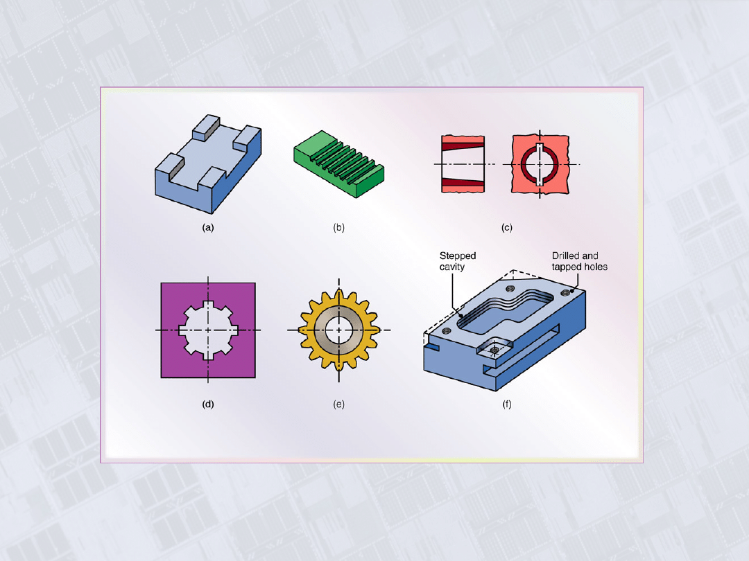
Parts Made with Machining Processes of
Chapter 24
Figure 24.1 Typical parts and shapes that can be
produced with the machining processes described in
this chapter.
Manufacturing, Engineering & Technology, Fifth Edition, by Serope Kalpakjian and Steven R. Schmid.
ISBN 0-13-148965-8. © 2006 Pearson Education, Inc., Upper Saddle River, NJ. All rights reserved.
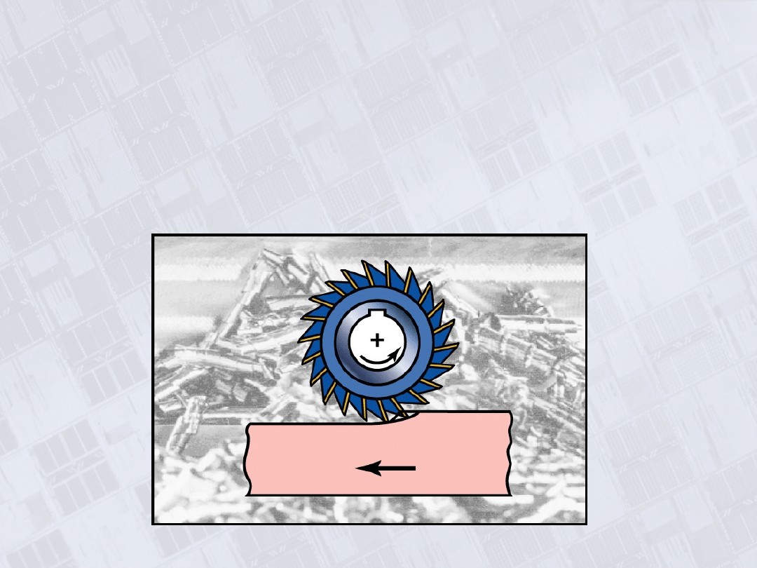
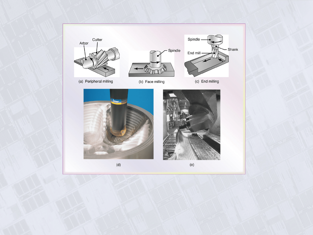
Milling Cutters and Milling Operations
Figure 24.2 Some basic types of milling cutters and milling operations. (a)
Peripheral milling. (b) Face milling. (c) End milling. (d) Ball-end mill with
indexable coated-carbide inserts machining a cavity in a die block. (e) Milling a
sculptured surface with an end mill, using a five-axis numerical control machine.
Source: (d) Courtesy of Iscar. (e) Courtesy of The Ingersoll Milling Machine
Co.
Manufacturing, Engineering & Technology, Fifth Edition, by Serope Kalpakjian and Steven R. Schmid.
ISBN 0-13-148965-8. © 2006 Pearson Education, Inc., Upper Saddle River, NJ. All rights reserved.
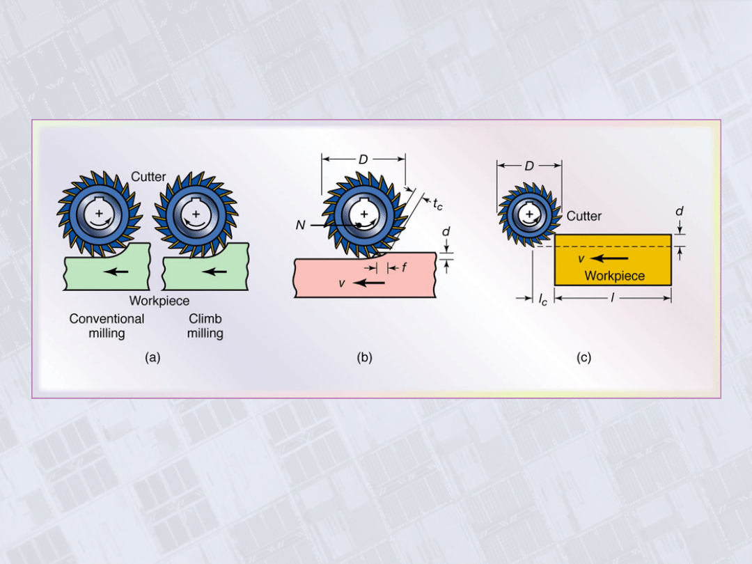
Milling Operations
Figure 24.3 (a) Schematic illustration of conventional milling and climb milling.
(b) lab-milling operation showing depth-of-cut, d; feed per tooth, f; chip depth-
of-cut, t
c
; and workpiece speed, v. (c) Schematic illustration of cutter travel
distance, l
c
, to reach full depth-of-cut.
Manufacturing, Engineering & Technology, Fifth Edition, by Serope Kalpakjian and Steven R. Schmid.
ISBN 0-13-148965-8. © 2006 Pearson Education, Inc., Upper Saddle River, NJ. All rights reserved.
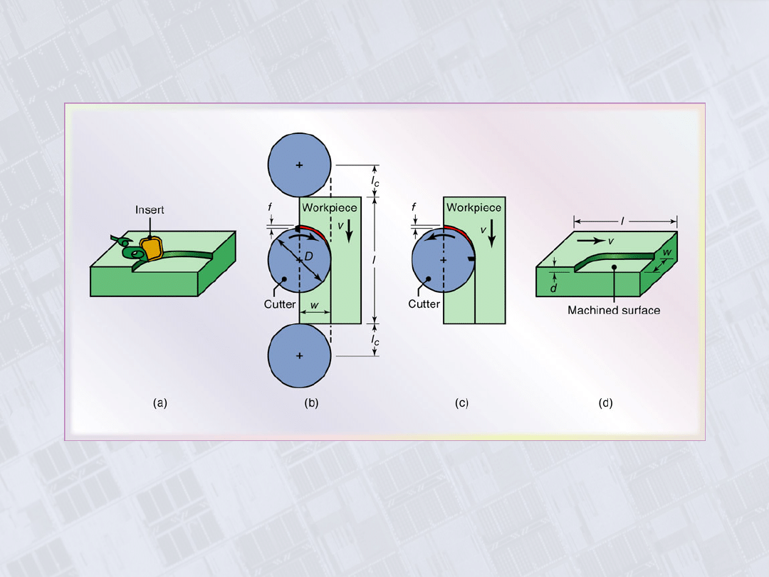
Face-Milling Operation
Figure 24.4 Face-milling operation showing (a) action of an insert in
face milling; (b) climb milling; (c) conventional milling; (d) dimensions
in face milling. The width of cut, w, is not necessarily the same as the
cutter radius.

Manufacturing, Engineering & Technology, Fifth Edition, by Serope Kalpakjian and Steven R. Schmid.
ISBN 0-13-148965-8. © 2006 Pearson Education, Inc., Upper Saddle River, NJ. All rights reserved.
Summary of Peripheral Milling Parameters and
Formulas
Manufacturing, Engineering & Technology, Fifth Edition, by Serope Kalpakjian and Steven R. Schmid.
ISBN 0-13-148965-8. © 2006 Pearson Education, Inc., Upper Saddle River, NJ. All rights reserved.
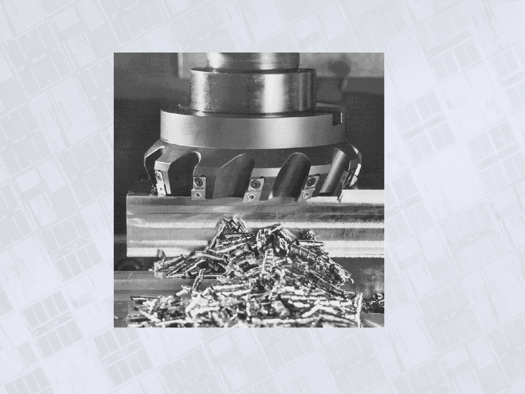
Face-Milling Cutter with Indexable Inserts
Figure 24.5 A face-milling cutter with indexable
inserts. Source: Courtesy of Ingersoll Cutting Tool
Company.
Manufacturing, Engineering & Technology, Fifth Edition, by Serope Kalpakjian and Steven R. Schmid.
ISBN 0-13-148965-8. © 2006 Pearson Education, Inc., Upper Saddle River, NJ. All rights reserved.
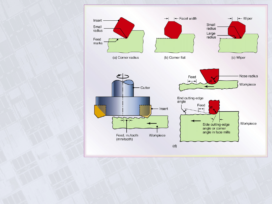
Effect of Insert
Shape on Feed
Marks on a Face-
Milled Surface
Figure 24.6 Schematic illustration of the effect of insert shape on feed marks on
a face-milled surface: (a) small corner radius, (b) corner flat on insert, and (c)
wiper, consisting of small radius followed by a large radius which leaves
smoother feed marks. (d) Feed marks due to various insert shapes.
Manufacturing, Engineering & Technology, Fifth Edition, by Serope Kalpakjian and Steven R. Schmid.
ISBN 0-13-148965-8. © 2006 Pearson Education, Inc., Upper Saddle River, NJ. All rights reserved.
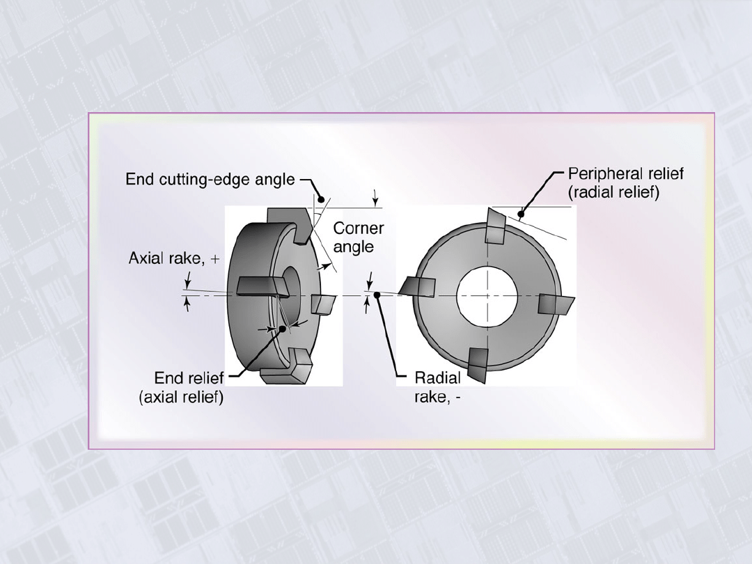
Face-Milling Cutter
Figure 24.7 Terminology for a face-milling
cutter.
Manufacturing, Engineering & Technology, Fifth Edition, by Serope Kalpakjian and Steven R. Schmid.
ISBN 0-13-148965-8. © 2006 Pearson Education, Inc., Upper Saddle River, NJ. All rights reserved.
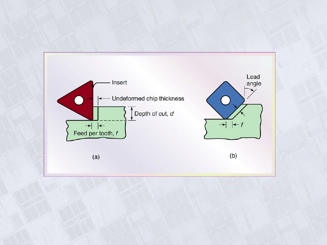
Effect of Lead Angle on Undeformed Chip
Thickness in Face Milling
Figure 24.8 The effect of the lead angle on the undeformed chip
thickness in face milling. Note that as the lead angle increases, the chip
thickness decreases, but the length of contact (i.e., chip width) increases.
The edges of the insert must be sufficiently large to accommodate the
contact length increase.
Manufacturing, Engineering & Technology, Fifth Edition, by Serope Kalpakjian and Steven R. Schmid.
ISBN 0-13-148965-8. © 2006 Pearson Education, Inc., Upper Saddle River, NJ. All rights reserved.
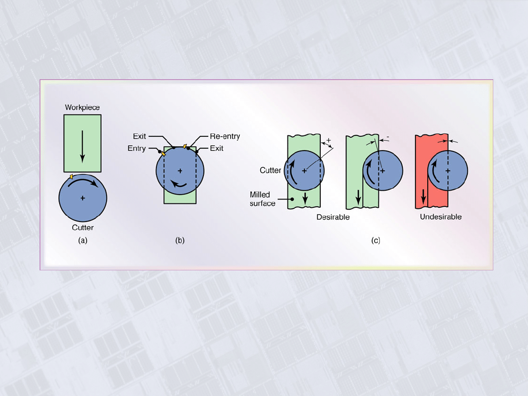
Position of Cutter and Insert in Face Milling
Figure 24.9 (a) Relative position of the cutter and insert as it first engages
the workpiece in face milling. (b) Insert positions towards the end of cut. (c)
Examples of exit angles of insert, showing desirable (positive or negative
angle) and undesirable (zero angle) positions. In all figures, the cutter
spindle is perpendicular to the page and rotates clockwise.
Manufacturing, Engineering & Technology, Fifth Edition, by Serope Kalpakjian and Steven R. Schmid.
ISBN 0-13-148965-8. © 2006 Pearson Education, Inc., Upper Saddle River, NJ. All rights reserved.
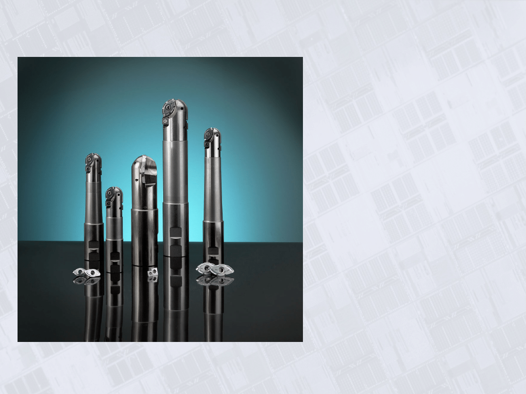
Ball Nose End
Mills
Figure 24.10 Ball nose end
mills. These cutters are able to
produce elaborate contours and
are often used in the machining
of dies and molds. (See also
Fig. 24.2d.) Source: Courtesy
of Dijet, Inc.
Manufacturing, Engineering & Technology, Fifth Edition, by Serope Kalpakjian and Steven R. Schmid.
ISBN 0-13-148965-8. © 2006 Pearson Education, Inc., Upper Saddle River, NJ. All rights reserved.
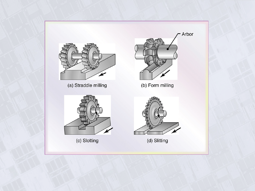
Cutters
Figure 24.11 Cutters for (a) straddle milling, (b)
form milling, (c) slotting, and (d) slitting with a
milling cutter.
Manufacturing, Engineering & Technology, Fifth Edition, by Serope Kalpakjian and Steven R. Schmid.
ISBN 0-13-148965-8. © 2006 Pearson Education, Inc., Upper Saddle River, NJ. All rights reserved.
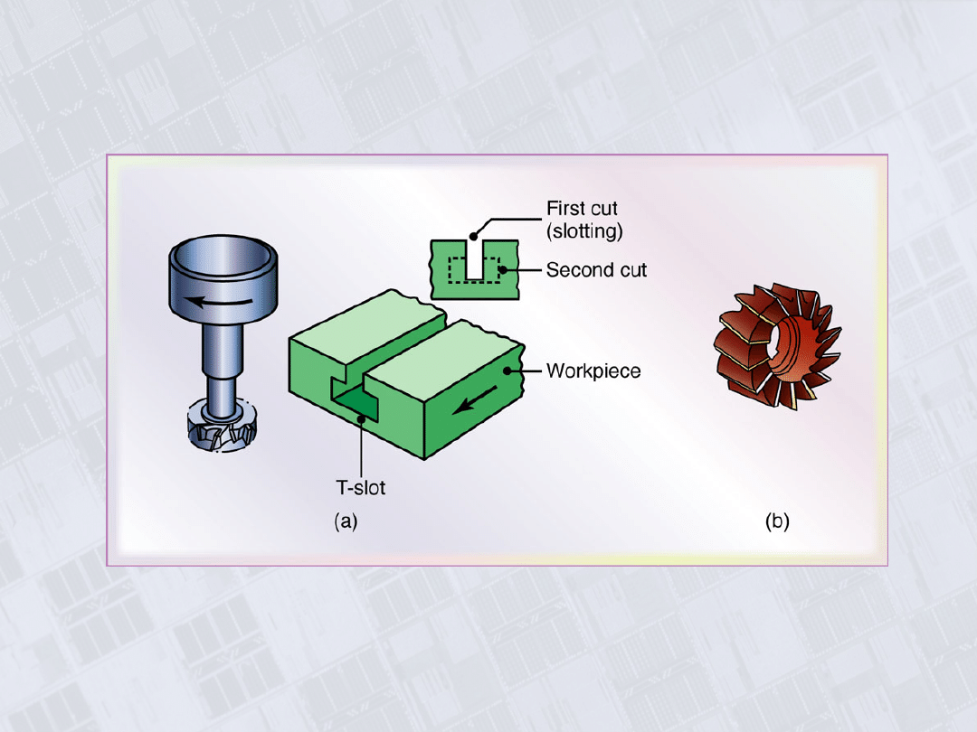
T-Slot Cutting and Shell Mill
Figure 24.12 (a) T-slot cutting with a milling cutter. (b) A
shell mill.
Manufacturing, Engineering & Technology, Fifth Edition, by Serope Kalpakjian and Steven R. Schmid.
ISBN 0-13-148965-8. © 2006 Pearson Education, Inc., Upper Saddle River, NJ. All rights reserved.
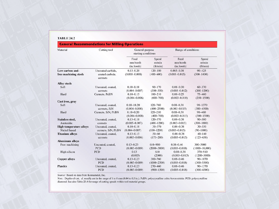
General Recommendations for Milling Operations
Manufacturing, Engineering & Technology, Fifth Edition, by Serope Kalpakjian and Steven R. Schmid.
ISBN 0-13-148965-8. © 2006 Pearson Education, Inc., Upper Saddle River, NJ. All rights reserved.
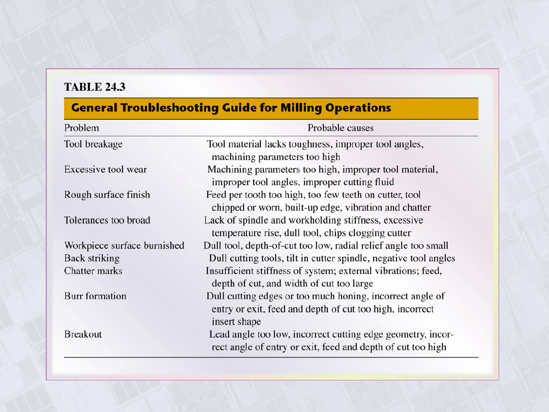
Troubleshooting Guide for Milling Operations
Manufacturing, Engineering & Technology, Fifth Edition, by Serope Kalpakjian and Steven R. Schmid.
ISBN 0-13-148965-8. © 2006 Pearson Education, Inc., Upper Saddle River, NJ. All rights reserved.
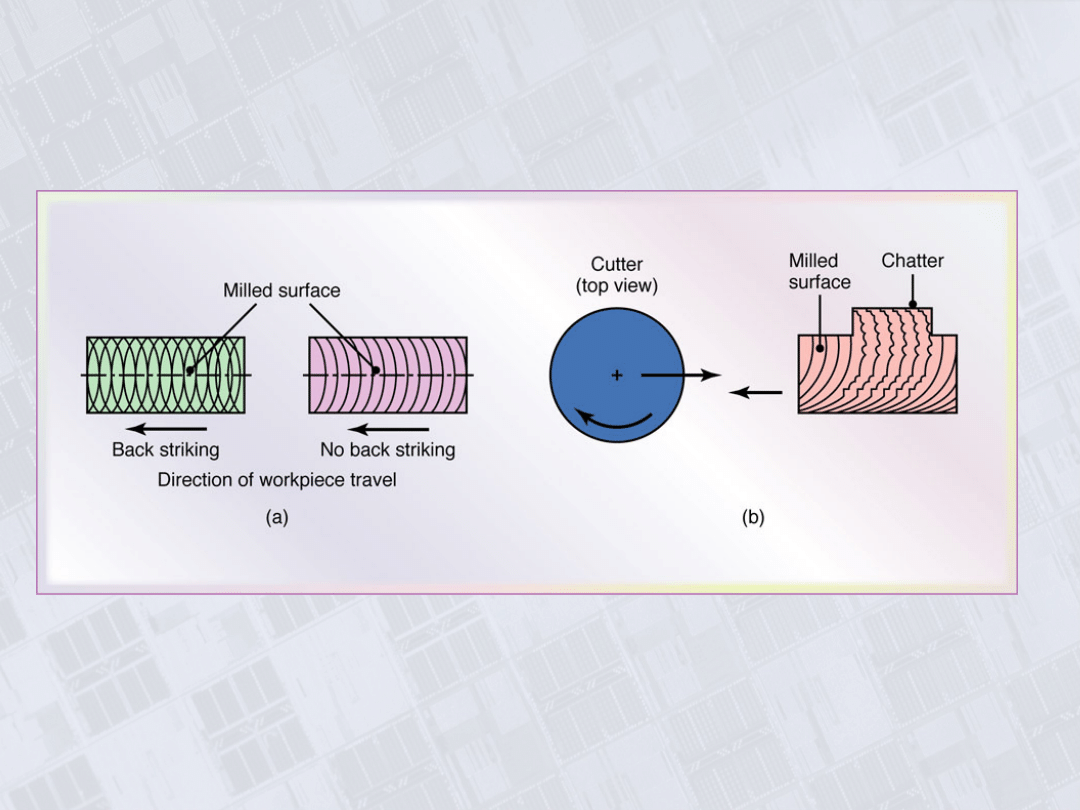
Machined Surface Features in Face Milling
Figure 24.13 Machined surface features in face milling. See also
Fig. 24.6.
Manufacturing, Engineering & Technology, Fifth Edition, by Serope Kalpakjian and Steven R. Schmid.
ISBN 0-13-148965-8. © 2006 Pearson Education, Inc., Upper Saddle River, NJ. All rights reserved.
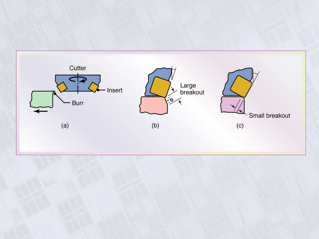
Edge Defects in Face Milling
Figure 24.14 Edge defects in face milling: (a) burr formation
along workpiece edge, (b) breakout along workpiece edge, and (c)
how it can be avoided by increasing the lead angle (see also last
row in Table 24.4).
Manufacturing, Engineering & Technology, Fifth Edition, by Serope Kalpakjian and Steven R. Schmid.
ISBN 0-13-148965-8. © 2006 Pearson Education, Inc., Upper Saddle River, NJ. All rights reserved.
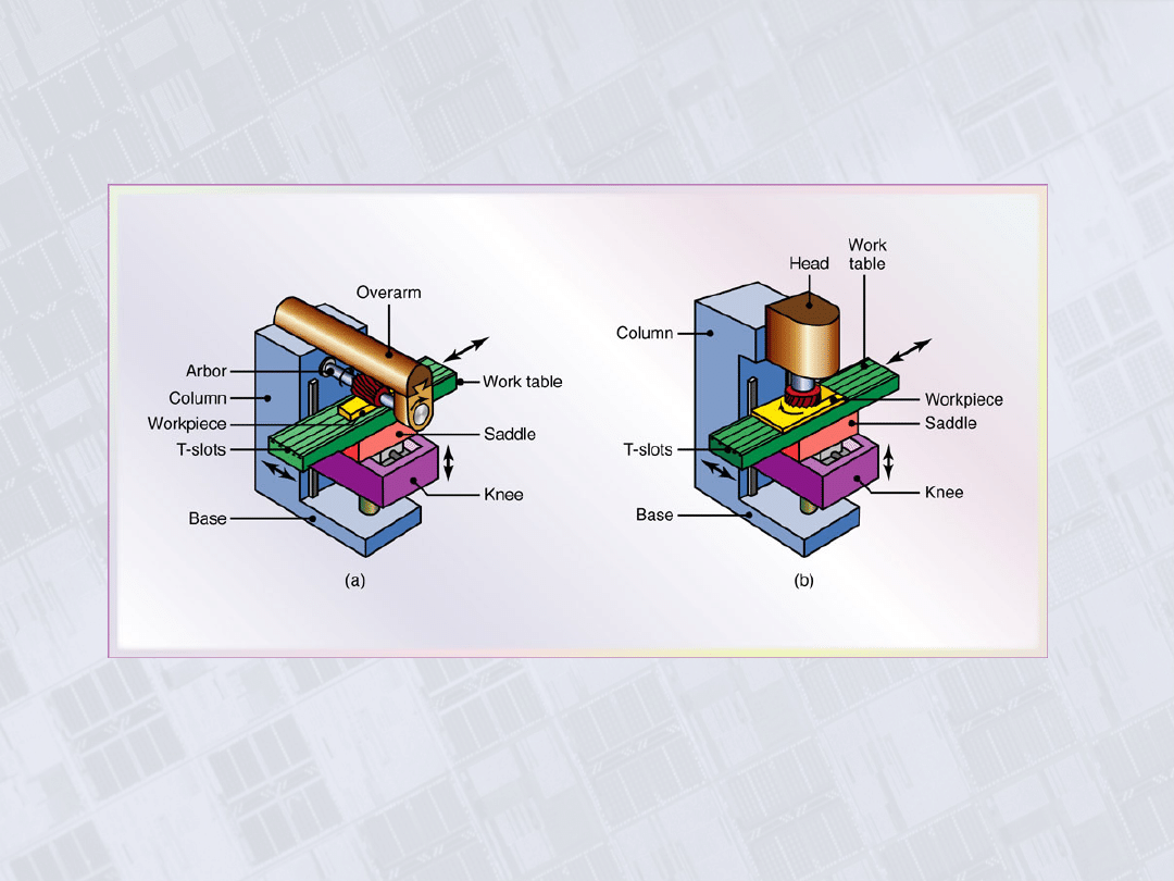
Column-and-Knee Type Milling Machines
Figure 24.15 Schematic illustration of (a) a horizontal-spindle
column-and-knee type milling machine and (b) vertical-spindle
column-and-knee type milling machine. Source: After G. Boothroyd.
Manufacturing, Engineering & Technology, Fifth Edition, by Serope Kalpakjian and Steven R. Schmid.
ISBN 0-13-148965-8. © 2006 Pearson Education, Inc., Upper Saddle River, NJ. All rights reserved.
CNC Vertical-Spindle Milling Machine
Figure 24.17 A computer numerical-control (CNC) vertical-
spindle milling machine. This machine is one of the most
versatile machine tools. The original vertical-spindle milling
machine iused in job shops is still referred to as a “Bridgeport”,
after its manufacturer in Bridgeport, Connecticut. Source:
Courtesy of Bridgeport Machines Dibision, Textron Inc.
Manufacturing, Engineering & Technology, Fifth Edition, by Serope Kalpakjian and Steven R. Schmid.
ISBN 0-13-148965-8. © 2006 Pearson Education, Inc., Upper Saddle River, NJ. All rights reserved.
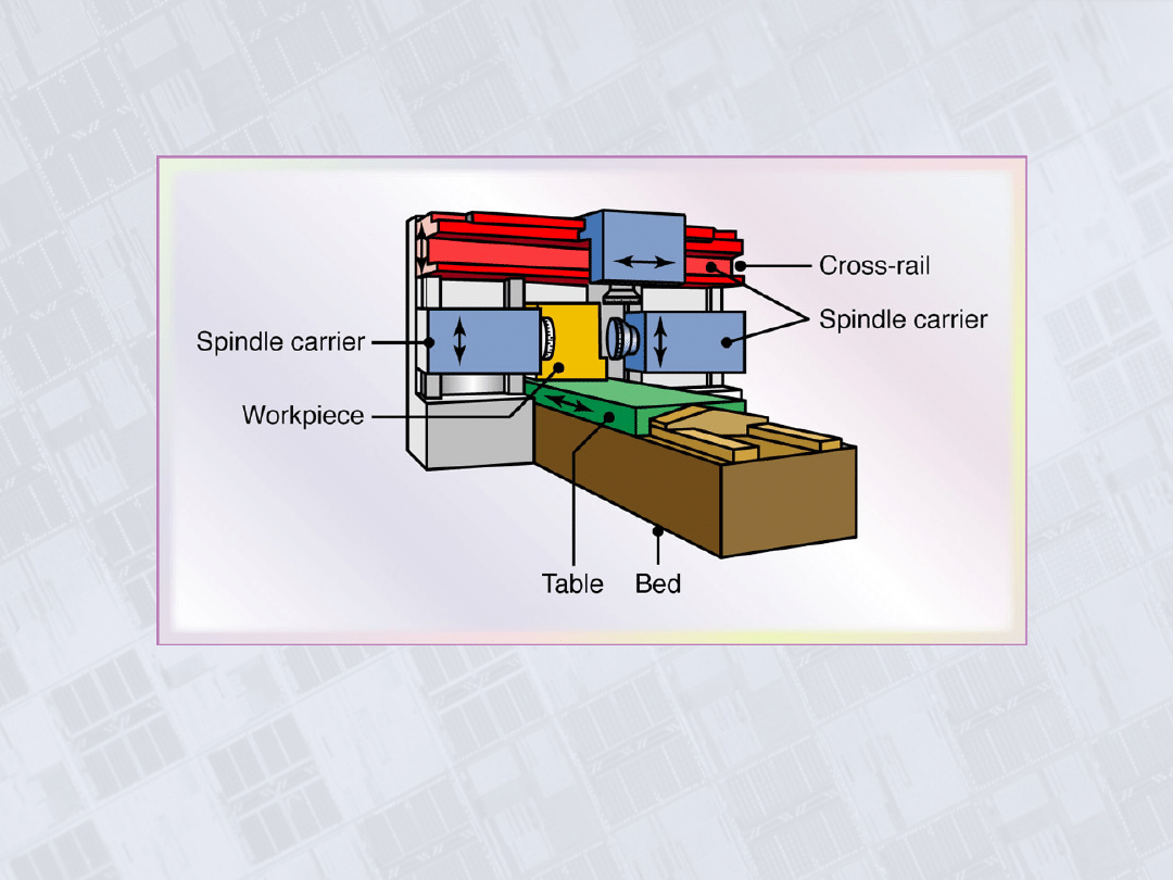
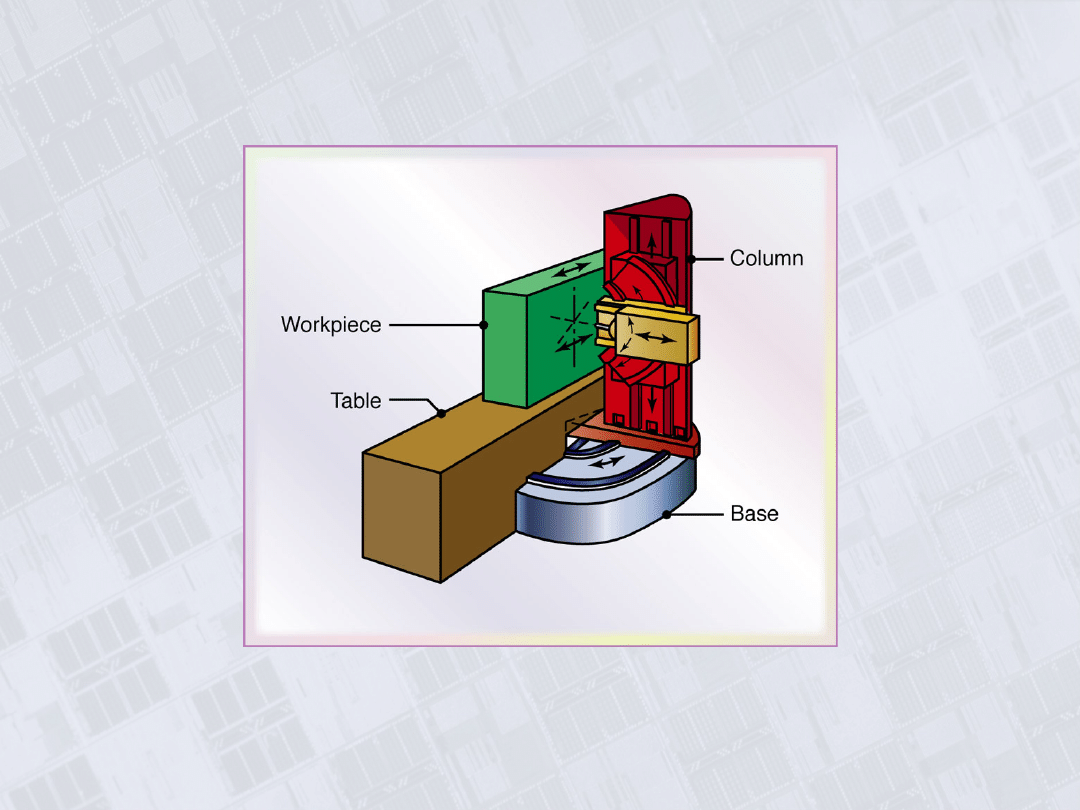
Five-Axis Profile Milling Machine
Figure 24.18 Schematic illustration of a five-axis profile milling machine.
Note that there are three principal linear and two angular movements of
machine components.
Manufacturing, Engineering & Technology, Fifth Edition, by Serope Kalpakjian and Steven R. Schmid.
ISBN 0-13-148965-8. © 2006 Pearson Education, Inc., Upper Saddle River, NJ. All rights reserved.
Parts Made on a Planer
Figure 24,19 Typical parts that can be made on a
planer.
Manufacturing, Engineering & Technology, Fifth Edition, by Serope Kalpakjian and Steven R. Schmid.
ISBN 0-13-148965-8. © 2006 Pearson Education, Inc., Upper Saddle River, NJ. All rights reserved.
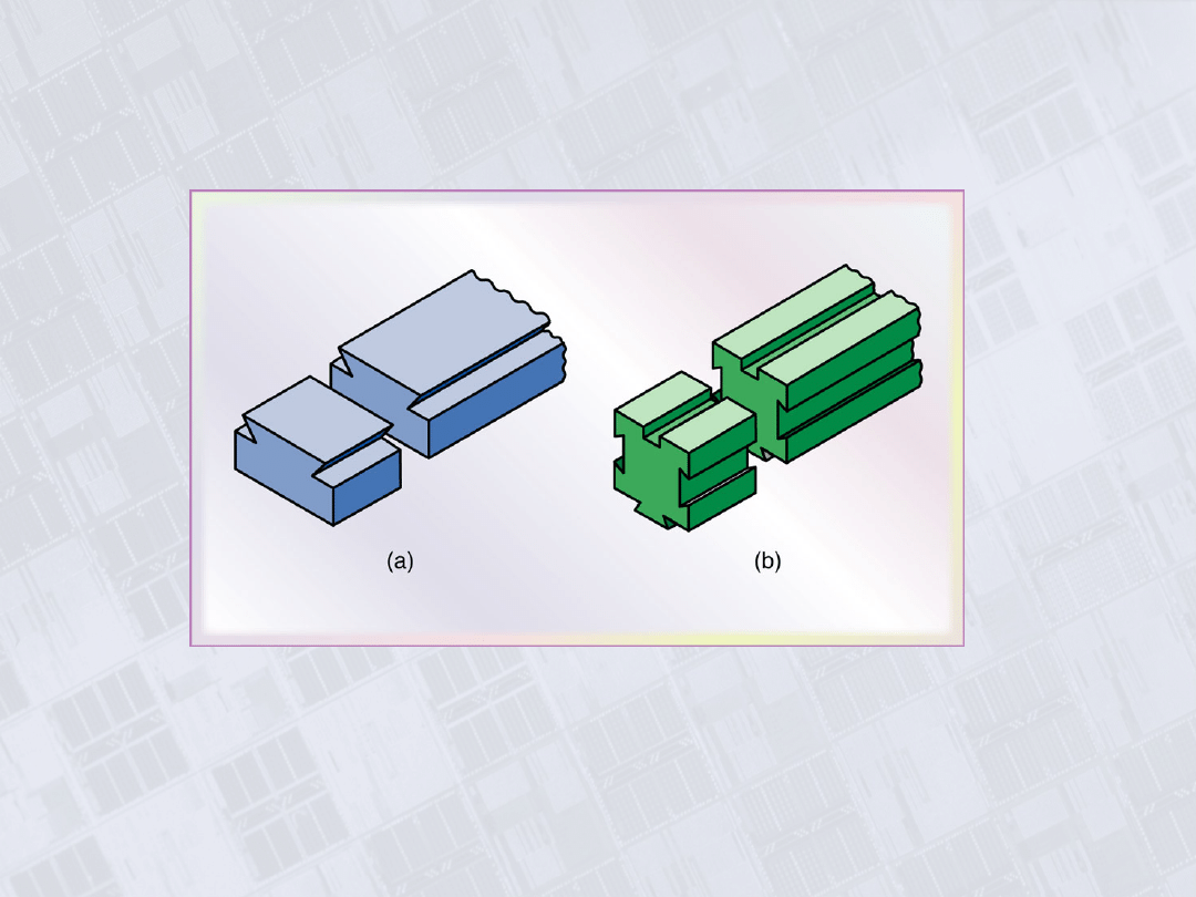
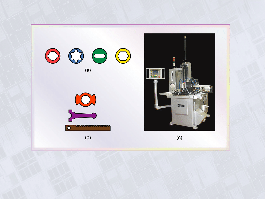
Broaching
Figure 24.20 (a) Typical parts made by internal broaching. (b) Parts made
by surface broaching. Heavy lines indicate broached surfaces. (c) Vertical
broaching machine. Source: (a) and (b) Courtesy of General Broach and
Engineering Company. (c) Courtesy of Ty Miles, Inc.
Manufacturing, Engineering & Technology, Fifth Edition, by Serope Kalpakjian and Steven R. Schmid.
ISBN 0-13-148965-8. © 2006 Pearson Education, Inc., Upper Saddle River, NJ. All rights reserved.
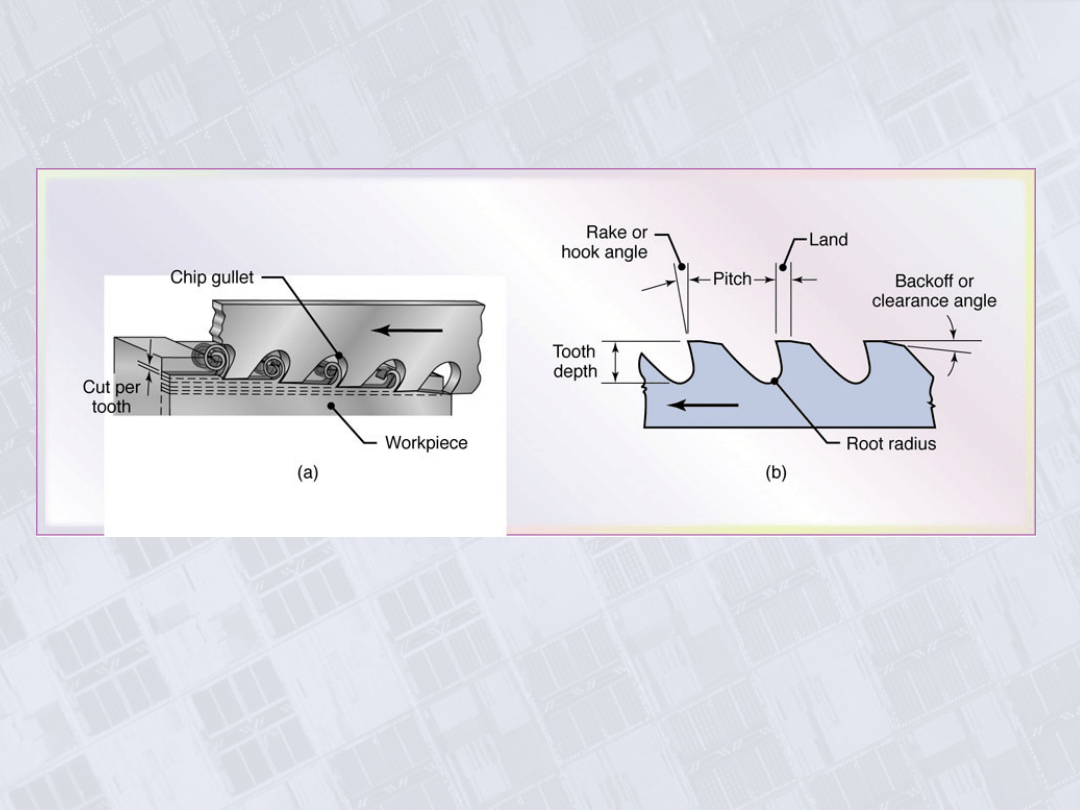
Broach Geometry
Figure 24.21 (a) Cutting action of a broach showing various
features. (b) Terminology for a broach.
Manufacturing, Engineering & Technology, Fifth Edition, by Serope Kalpakjian and Steven R. Schmid.
ISBN 0-13-148965-8. © 2006 Pearson Education, Inc., Upper Saddle River, NJ. All rights reserved.
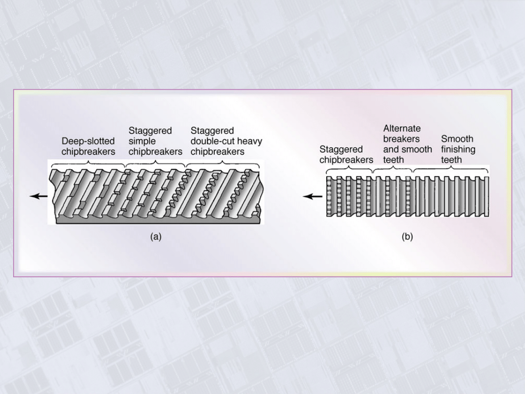
Chipbreaker Features on Broaches
Figure 24.22 Chipbreaker features on (a) a flat broach and (b) a round
broach.
Manufacturing, Engineering & Technology, Fifth Edition, by Serope Kalpakjian and Steven R. Schmid.
ISBN 0-13-148965-8. © 2006 Pearson Education, Inc., Upper Saddle River, NJ. All rights reserved.
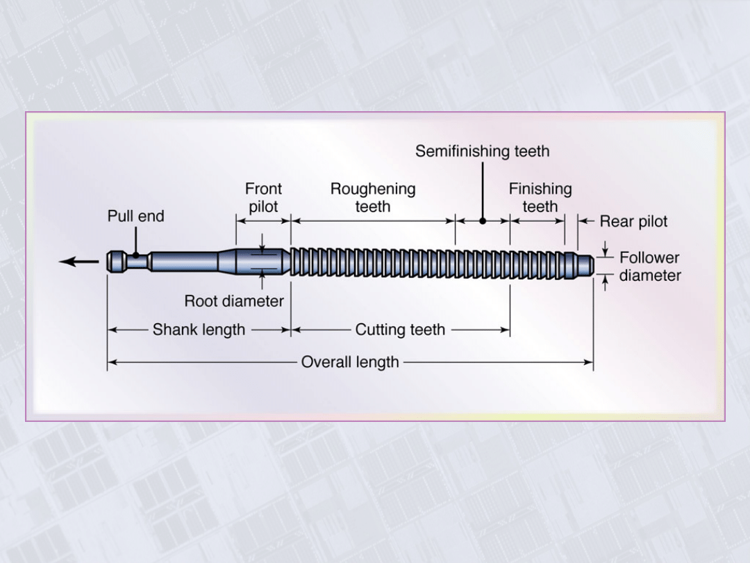
Pull-Types Internal Broach
Figure 24.23 Terminology for a pull-type internal broach used for enlarging
long holes.
Manufacturing, Engineering & Technology, Fifth Edition, by Serope Kalpakjian and Steven R. Schmid.
ISBN 0-13-148965-8. © 2006 Pearson Education, Inc., Upper Saddle River, NJ. All rights reserved.
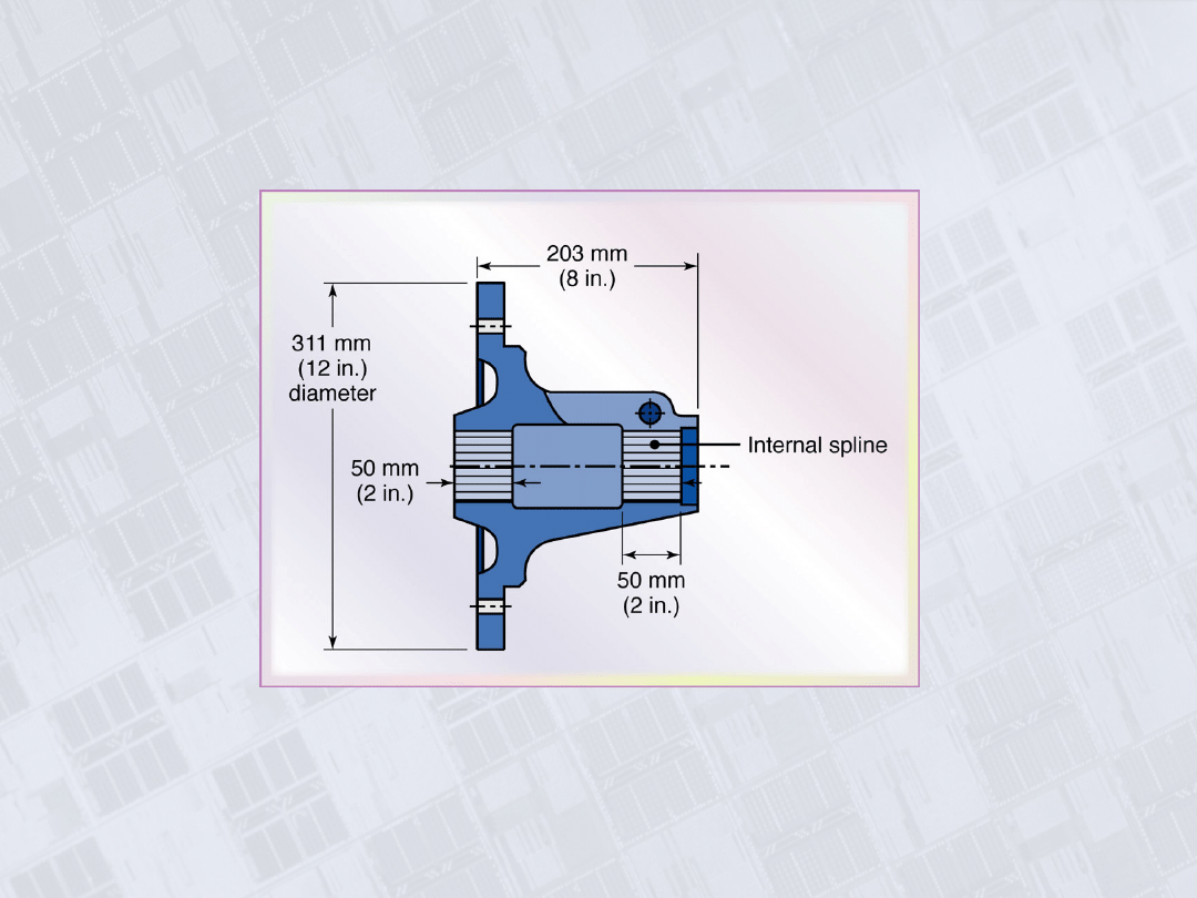
Part with Internal Splines Made by Broaching
Figure 24.24 Example of a part with internal splines produced by
broaching.
Manufacturing, Engineering & Technology, Fifth Edition, by Serope Kalpakjian and Steven R. Schmid.
ISBN 0-13-148965-8. © 2006 Pearson Education, Inc., Upper Saddle River, NJ. All rights reserved.
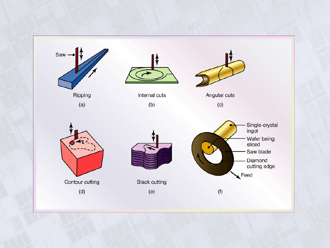
Sawing Operations
Figure 24.25 Examples of various sawing
operations.
Manufacturing, Engineering & Technology, Fifth Edition, by Serope Kalpakjian and Steven R. Schmid.
ISBN 0-13-148965-8. © 2006 Pearson Education, Inc., Upper Saddle River, NJ. All rights reserved.
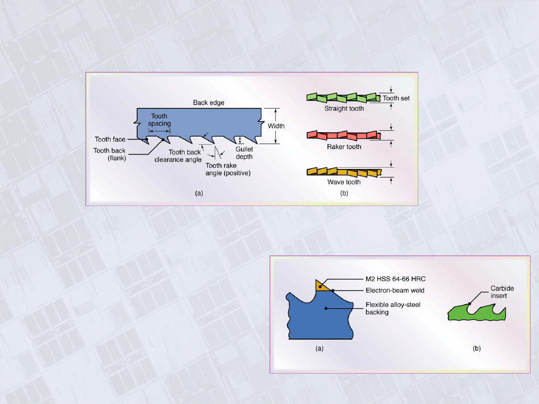
Saw Teeth
Figure 24.26 (a) Terminology for saw teeth. (b) Types of tooth sets on saw
teeth staggered to provide clearance for the saw blade to prevent binding
during sawing.
Figure 24.27 (a) High-
speed-steel teeth
welded on a steel blade.
(b) Carbide inserts
brazed to blade teeth.

Manufacturing, Engineering & Technology, Fifth Edition, by Serope Kalpakjian and Steven R. Schmid.
ISBN 0-13-148965-8. © 2006 Pearson Education, Inc., Upper Saddle River, NJ. All rights reserved.
Types of Burs
Figure 24.28 Types of burs used in burring
operations.
Manufacturing, Engineering & Technology, Fifth Edition, by Serope Kalpakjian and Steven R. Schmid.
ISBN 0-13-148965-8. © 2006 Pearson Education, Inc., Upper Saddle River, NJ. All rights reserved.
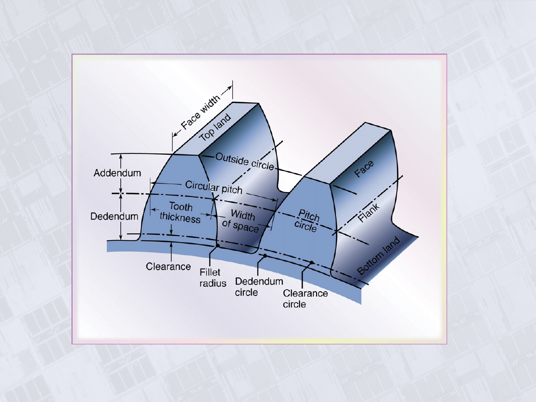
Involute Spur Gear
Figure 24.29 Nomenclature for an involute spur
gear.
Manufacturing, Engineering & Technology, Fifth Edition, by Serope Kalpakjian and Steven R. Schmid.
ISBN 0-13-148965-8. © 2006 Pearson Education, Inc., Upper Saddle River, NJ. All rights reserved.
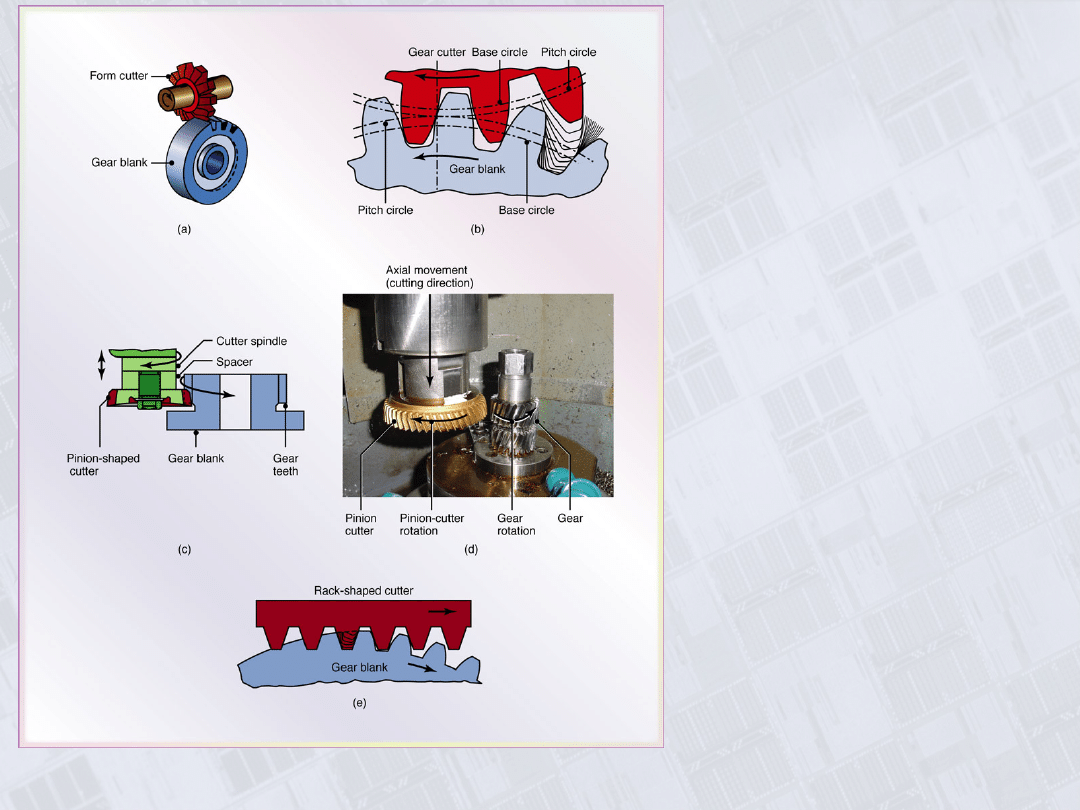
Gear Generating
with Various
Cutters
Figure 24.30 (a) Producing
gear teeth on a blank by
form cutting. (b) Schematic
illustration of gear
generating with a pinion-
shaped gear cutter. (c) and
(d) Gear generating on a
gear shaper using a pinion-
shaped cutter. Note that the
cutter reciprocates vertically.
(e) Gear generating with
rack-shaped cutter. Source:
(d) Schafer Gear Works, Inc.
Manufacturing, Engineering & Technology, Fifth Edition, by Serope Kalpakjian and Steven R. Schmid.
ISBN 0-13-148965-8. © 2006 Pearson Education, Inc., Upper Saddle River, NJ. All rights reserved.
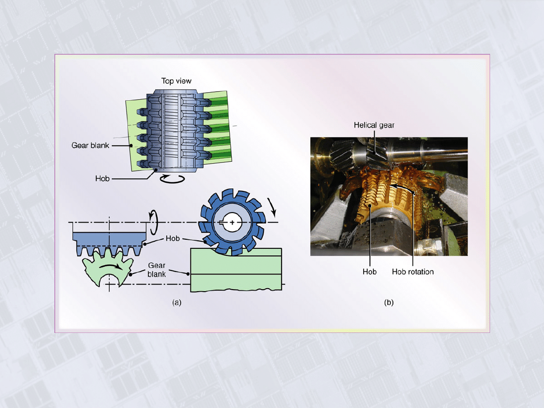
Hobbing
Figure 24.31 (a) Schematic illustration of gear cutting with a hob. (b)
Production of worm gear through hobbing. Source: Courtesy of Schafer
Gear Works, Inc.
Manufacturing, Engineering & Technology, Fifth Edition, by Serope Kalpakjian and Steven R. Schmid.
ISBN 0-13-148965-8. © 2006 Pearson Education, Inc., Upper Saddle River, NJ. All rights reserved.
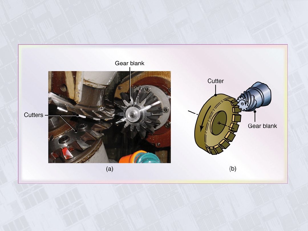
Bevel Gears
Figure 24.32 (a) Cutting a straight bevel-gear blank with two
cutter. (b) Cutting a helical bevel gear. Source: Courtesy of
Schafer Gear Works, Inc.
Manufacturing, Engineering & Technology, Fifth Edition, by Serope Kalpakjian and Steven R. Schmid.
ISBN 0-13-148965-8. © 2006 Pearson Education, Inc., Upper Saddle River, NJ. All rights reserved.
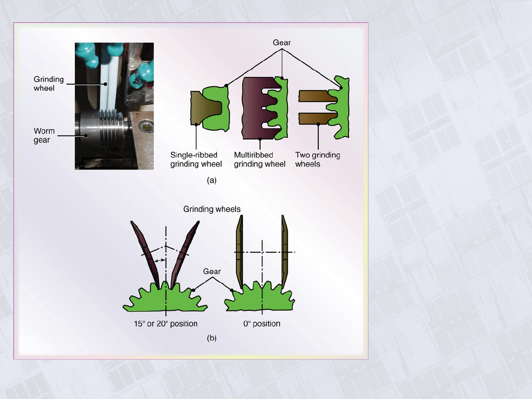
Finishing Gears
by Grinding
Figure 24.33 Finishing
gears by grinding: (a)
form grinding with
shaped grinding
wheels; (b) grinding
by generating with
two wheels.
Manufacturing, Engineering & Technology, Fifth Edition, by Serope Kalpakjian and Steven R. Schmid.
ISBN 0-13-148965-8. © 2006 Pearson Education, Inc., Upper Saddle River, NJ. All rights reserved.
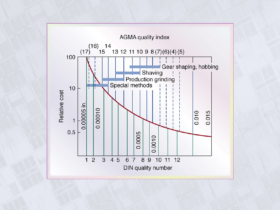
Gear Manufacturing Cost as a Function of Gear
Quantity
Figure 24.34 Gear manufacturing cost as a function of gear
quality. The numbers along the vertical lines indicate
tolerances.
Document Outline
- Chapter 24
- Parts Made with Machining Processes of Chapter 24
- Milling Cutters and Milling Operations
- Milling Operations
- Face-Milling Operation
- Summary of Peripheral Milling Parameters and Formulas
- Face-Milling Cutter with Indexable Inserts
- Effect of Insert Shape on Feed Marks on a Face-Milled Surface
- Face-Milling Cutter
- Effect of Lead Angle on Undeformed Chip Thickness in Face Milling
- Position of Cutter and Insert in Face Milling
- Ball Nose End Mills
- Cutters
- T-Slot Cutting and Shell Mill
- General Recommendations for Milling Operations
- Troubleshooting Guide for Milling Operations
- Machined Surface Features in Face Milling
- Edge Defects in Face Milling
- Column-and-Knee Type Milling Machines
- CNC Vertical-Spindle Milling Machine
- Five-Axis Profile Milling Machine
- Parts Made on a Planer
- Broaching
- Broach Geometry
- Chipbreaker Features on Broaches
- Pull-Types Internal Broach
- Part with Internal Splines Made by Broaching
- Sawing Operations
- Saw Teeth
- Types of Burs
- Involute Spur Gear
- Gear Generating with Various Cutters
- Hobbing
- Bevel Gears
- Finishing Gears by Grinding
- Gear Manufacturing Cost as a Function of Gear Quantity
Wyszukiwarka
Podobne podstrony:
Ch24
ch24
86 1225 1236 Machinability of Martensitic Steels in Milling and the Role of Hardness
ch24
CH24
84 1199 1208 The Influence of Steel Grade and Steel Hardness on Tool Life When Milling
Ch24 Calculate Stress on 3D Parts
lathe millingattachment plans
Lekcja 7 - Milline ilm täna on, Język Estoński
87 1237 1248 Machinability and Tool Wear During the High Speed Milling of Some Hardened
making vise clamps on the milling machine
Ch24 Solations Brigham 10th E
Ch24 04
the milliners daughter
Synge John Millington JEŹDŹCY DO MORZA
więcej podobnych podstron