
Service
ECC
Issue 1
European Service
Guide to ESD
ECC G001
S
amsung
E
uropean
S
ervice
A
ward
Revised Date:
Page 1 of 12
ELECTRONICS
What is ESD?
ESD stands for Electro Static Discharge.
Static electricity is an everyday phenomenon - there can be few of us who have not
experienced a static shock after walking across a room and touching the door knob, or on
getting out of a car.
Other static nuisance effects include the cling of some fabrics to the body, the sticking of a
plastic document cover, or the attraction of dust to a TV or computer screen.
While we can feel some of these effects, static electricity is normally present at lower levels
that we cannot feel, hear or see, but may nevertheless damage sensitive electronic
components. It can build up rapidly on objects, in unexpected ways, to produce surprisingly
high voltages.
If two objects that have different voltages approach each other closely enough, charge may
pass from one object to the other in a fast electrostatic discharge. While this only lasts a
microsecond or less, the peak discharge current can be several Amps and the peak power
can be in the kilowatt range!
Why worry about ESD?
ESD can cause unseen damage to electronic components during manufacture of electronic
assemblies and equipment. If the damaged component fails immediately
(Catastrophic
Damage), the result can be a board that fail tests and requires rework. This represents lost
production and additional manufacturing costs.
Worse than this, a component may be partially damaged and weakened (Latent Damage). It
may suffer a change or drift in characteristics. It may remain within specification, but fail later
when in use by a customer. It has been estimated that 90% of damaged devices may be
discovered in this way. This is the most expensive type of failure, as it represents:
• Customer dissatisfaction, and the possibility of loss of product reputation and future
sales
• Customer service personnel and facility cost
• Engineers time, possibly for on-site repair with travel, and parts replacement
In manual assembly most ESD arises from charged personnel, if they are not grounded.
Most people do not feel an ESD shock unless they are charged to over 4000v, 2000V you can
visibly see
,
(the sensitivity threshold varies between people, and even over parts of the body!).
This voltage is quite common in the uncontrolled environment - how many of us have not felt
the occasional electrostatic shock in everyday life?
Low Humidity
The electrostatic properties of materials are very dependent on atmospheric humidity. A
controlled humidity of 50 %rh suits most circumstances. If humidity reduces below 20 %rh,

Service
ECC
Issue 1
European Service
Guide to ESD
ECC G001
S
amsung
E
uropean
S
ervice
A
ward
Revised Date:
Page 2 of 12
ELECTRONICS
ensure that selected materials and equipment will perform effectively under operational
conditions.
Clean room conditions
Some current materials and techniques in use for ESD protection are not suitable for use in
clean rooms (class 100 or tighter).
Where high voltages may be present
If high voltages greater than 250VAC or 500VDC are present then take particular care to
consider safety requirements.
Definitions
Antistatic
This can mean a wide variety of things, and is deprecated by the writers of 61340-5-1.
Although the term is widely used, it is better to avoid it if possible.
ESD
ElectroStatic Discharge. When the electric field strength in air becomes sufficiently high, its
insulating properties break down and charge can flow away in a rapid discharge. ESD can
have very short duration high current levels and and cause ignition of flammable materials or
damage to electronic components.
ESDS
ElectroStatic Discharge Sensitive device. An electronic component that could be damaged by
ESD.
Field work
Handling of ESDS within a temporary EPA, for example at the customer's site.
EPA
ESD Protected Area. An area in which static electricity is kept below levels that could cause
damage to electronic components handled within the area.
Intimate packaging
Packaging that makes contact with ESDS, for example the inner surface of an ESD protective
bag.
Proximity packaging
Material not making contact with ESDS but which is used to enclose one or more devices. For
example the outer surface of an ESD protective bag, or ESD packaging used to contain
ESDS already within other packaging.
Secondary packaging
Material used primarily to give additional physical protection to the outside of proximity
package e.g. cardboard boxes, padded bags, polythene wrap.

Service
ECC
Issue 1
European Service
Guide to ESD
ECC G001
S
amsung
E
uropean
S
ervice
A
ward
Revised Date:
Page 3 of 12
ELECTRONICS
Low charging
Packaging exhibiting properties which minimises any charge generation.
Conductive
The word "conductive" has a range of meanings within the context of different standards and
should be treated with care.
1.
any material that conducts electricity, i.e. not an insulator
2.
Within the 61340-5-1standard, "electrostatic conductive" packaging material has
surface resistance between 10
2
Ω and 10
5
Ω
3.
"conductive" has no specific meanings for other materials or equipment under 61340-
5-1 although it is often generally used to indicate materials having resistance values <
10
6
Ω
4.
specific meanings for other equipment are possible, e.g. "conductive footwear"
Dissipative
The word "dissipative" has a range of meanings within the context of different standards and
should be treated with care.
1.
Within the 61340-5-1standard, "electrostatic dissipative" packaging material has
surface resistance between 10
5
Ω and 10
11
Ω
2.
"dissipative" has no specific meanings for other materials or equipment under 61340-
5-1 although it is often generally used to indicate materials having resistance values <
10
12
Ω and > < 10
6
Ω
3.
specific meanings for other equipment are possible, e.g. "conductive footwear"
Electrostatic discharge shielding packaging
Packaging, barrier or enclosure that limits the passage of ESD current and attenuates the
energy resulting from an electrostatic discharge such that the maximum energy from 1000 V
HBM ESD applied to the outside of the packaging is less than or equal to 50 nJ measured
inside the packaging.
Surface resistance
This is the resistance of a surface measured by a concentric ring electrode test method
defined in 61340-5-1and IEC 61340-2-3: 2000. It is NOT the same as "surface resistivity" and
is typically about a factor of 10 less than surface resistivity as measured in the old EN100015
method.
Point-to-point resistance
The is the resistance measured between two electrodes placed on a surface, defined in
61340-5-1, IEC 61340-2-3: 2000 and ESD S11.11- 2001
Resistance-to-ground
This is the electrical resistance measured from a point to the ESD facility electrical earth
(usually mains power earth).
Key elements in an ESD Program

Service
ECC
Issue 1
European Service
Guide to ESD
ECC G001
S
amsung
E
uropean
S
ervice
A
ward
Revised Date:
Page 4 of 12
ELECTRONICS
Principles of electrostatic safe handling
There are two simple principles we can use to protect ESD sensitive components from ESD
damage:
•
Only handle sensitive components in an ESD Protected Area
(EPA) under
protected and controlled conditions
•
Protect sensitive devices outside the EPA
using ESD protective packaging
What is an EPA?
An EPA is an area that is maintained safe for handling static sensitive components by
keeping electrostatic fields and voltages to an insignificantly low level. An EPA should have
well defined boundaries so that it is clear where the safe area is entered and left.
Insulating materials are strong ESD sources and so they are excluded from the EPA where
possible. Where this is not possible special measures such as ionisers are used to neutralise
electrostatic charges.
All non-insulating and conductive objects are grounded, so that electrostatic charge cannot
build up on these. Most importantly, all personnel (people are conductive objects!) are
grounded so that they do not charge to high voltages. There are two ways in which people are
grounded:
• Using a grounded wrist strap (this is the preferred method)
• Using conductive footwear (conductive or dissipative shoes, or heel & toe straps on
both feet) in conjunction with a grounded conductive floor.
Three key elements of an effective ESD program
An effective ESD program requires three main parts:
•
The ESD Program.
This is a document that specifies the equipment used, and
procedures followed in order to ensure electrostatic safe handling.
•
The Training program.
This is required in order to make sure that everyone is aware
of, and understands the ESD Program, use of equipment and correct procedures.
•
The Audit program.
This is required in order to make sure that equipment remains
functional, and that the ESD Program procedures are correctly followed.
If any of these is absent, it is likely that the ESD prevention measures will eventually fail. A
fourth factor is also extremely important -
Management commitment.
If Management does
not provide the resources and authoritative support required, it is unlikely that the ESD
Program will succeed.
EPA design
Design philosophy
A primary objective of EPA design is that all personnel handling sensitive devices are
grounded. The preferred means of grounding personnel is by using wrist straps. If this is not

Service
ECC
Issue 1
European Service
Guide to ESD
ECC G001
S
amsung
E
uropean
S
ervice
A
ward
Revised Date:
Page 5 of 12
ELECTRONICS
practical, use compliant footwear or heel and toe straps with compliant flooring. Seated
personnel should be grounded via wrist straps - footwear grounding is not reliable in this case,
and grounding via the seat should not be considered a reliable option.
Any surfaces on which ESDS are placed must be connected to EPA ground, and have a
point-to-point resistance between 10
4
Ω and 10
10
Ω, and resistance-to-ground between
7.5x10
5
Ω and 10
9
Ω. The ESD Coordinator can authorise "hard grounding" (<10
4
Ω) of
surfaces when required.
General design
An EPA (Electrostatic Protected Area) is a region within which no item or activity must be able
to cause damage to a sensitive device. In the simplest case - a field work station - it may
consist of a dissipative mat, a wrist strap and common grounding facility for both. At the other
extreme it may consist of a large manufacturing area where all the measures of 61340-5-1
are implemented. In some cases the EPA may consist of a single bench work area, which
may not have an EPA floor.
The ESD Coordinator is responsible for determining EPA boundaries, construction, selection
of equipment and general appropriate design of EPA for their particular
application. Equipment used within the EPA must comply with the requirements of 61340-5-
1.
If possible, a group of EPA work stations should be combined into one large EPA, including
an EPA compliant floor. If this is not carried out and each work station forms an individual
EPA (which may not include an EPA floor), sensitive devices must then be packaged in ESD
protective packaging for transport between work stations.
Marking the EPA boundaries
Personnel must be able to see signs complying with 61340-5-1 before they enter the EPA.
Where appropriate (i.e. in a multistation EPA), compliant signs must also be visible within the
EPA, and exit signs should mark the boundary of the EPA.
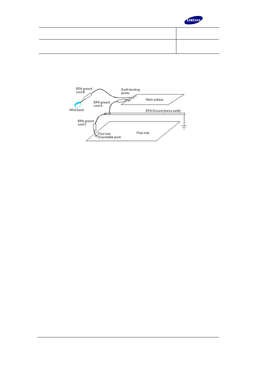
EPA ground system design
The EPA ground provides a low resistance path (<2
Ω) to ground, usually to mains protective
earth. A single EPA ground must be used within one EPA facility.
EPA ground bonding points (EBP) must be provided next to each working area or
surface. These are points to which wrist straps are connected, and must be clearly marked in
compliance with 61340-5-1. There must be sufficient EBPs to provide for operators and
visitors, and they must be accessible. EBP are connected to EPA ground through a
resistance of up to 10
6
Ω.
Surface to ground resistance values may be achieved by including discrete resistors in the
ground path, or by the resistance of the material which is directly grounded.
EPA ground cords are used to connect between groundable points and the EPA ground
facility. One or more resistor may be included in the ground cord to give the required
Service
ELECTRONICS
ECC
Issue 1
European Service
Guide to ESD
ECC G001
S
amsung
E
uropean
S
ervice
A
ward
Revised Date:
Page 6 of 12
resistance to ground value. If a single resistor is used, it must be at the end of the cord at the
groundable point. If more than one resistor is included, the resistor at the end connected to
the groundable point must be at least half the total resistance in the cord. The ground cord
connections, if accessible, must be shrouded with insulating material.
The EPA ground connection system must not be compatible with any connecting system used
for any other purpose. The conducting parts of the connectors must be shrouded by insulating
material when a cord is connected to the bonding point.
Wrist straps
A wrist strap has a snugly fitting band worn around the wrist, and cord fitted with a quick
release connection. The resistance between the band inner surface and the groundable point
must be less than 10
5
Ω. The conducting parts of the connecting system must be shrouded
when connected. The strap ground cord must incorporate a resistor (7.5x10
5
Ω to 5x10
6
Ω ) at
the wrist end (see EPA ground cord B). The total resistance from hand to Earth Bonding Point
must be between 7.5x10
5
Ω and 3.5x10
7
Ω.
Certification of conformance
The ESD Coordinator must audit a new or modified EPA to ensure that compliance is
achieved, and must issue a Certificate of Conformance before the EPA is used.
Departures from the guidance of the 61340-5-1 Technical Report should be recorded on the
Certificate of Conformance, along with any extra equipment or procedures required to ensure
ESD protection.
Responsibilities of personnel
Responsibilities of all personnel
All personnel handling sensitive devices have responsibility to be aware of the ESD threat to
reliability of electronic products. They have prime responsibility to implement and maintain
ESD prevention measures. Any failure to do so should be reported to the ESD Co-ordinator.
All personnel are expected to inform the ESD Co-ordinator of any unsatisfactory measures,
and suggest improvements or corrective actions if appropriate.

Service
ECC
Issue 1
European Service
Guide to ESD
ECC G001
S
amsung
E
uropean
S
ervice
A
ward
Revised Date:
Page 7 of 12
ELECTRONICS
General Management responsibilities
61340-5-1 places responsibility for implementation of the guidelines of the Technical Report in
the hands of General Management. They are also ultimately responsible for making sure that
all aspects of ESDS handling are carried out, including;
• Maintaining a register of trained personnel
• Providing appropriate training for all personnel
• Ensuring
inspection,
supervision and maintenance of EPA facilities are carried out
The General Management bear the responsibility for
a
ppointment of the site ESD Co-
ordinator. A named ESD Co-ordinator is required for each site. They must be given total
Management back-up, and adequate resources and authority.
ESD Co-ordinator responsibilities
The ESD Co-ordinator is responsible to the Management for all site ESD matters. This
includes;
• Ensuring that a copy of the ESD Program or 61340-5-1 standard is available to all
relevant personnel
• Specifying and maintaining a list of ESD equipment
• Making sure ESD training is adequate and conforms to the requirements
• Maintaining a list of trained personnel
• Ensuring that all equipment and procedures conform to the standard
• Inspection, maintenance and verifying conformance of the EPA
• Making ESD program tailoring decisions when required
• Giving assistance when required
The ESD Co-ordinator has responsibility for making certain technical decisions in tailoring the
implementation of the ESD Program:
• Defining the boundaries of Electrostatic Protected Areas (EPA)
• Defining and selecting equipment for use within the EPA
• Construction and certification of EPAs
• Deciding which (if any) of the recommended measures are not required
• Deciding the frequency of certain audit actions
The ESD Co-ordinator can appoint deputies if required.
ESD Protective packaging
Definition of the types of packaging
61340-5-1 defines three types of packaging - intimate, proximity, and secondary packaging:
Term
Definition

Service
ECC
Issue 1
European Service
Guide to ESD
ECC G001
S
amsung
E
uropean
S
ervice
A
ward
Revised Date:
Page 8 of 12
ELECTRONICS
Intimate
packaging
Packaging material which may make contact with the ESDS
Proximity
packaging
Does not make contact with the ESDS, but may enclose one or more ESDS
Secondary
packaging
Mainly used to give physical protection, is kept away from ESDS and is not
allowed in the EPA.
Warning labels (compliant with 61340-5-1) must appear on all packages containing ESDS. If
removed for access, they must be replaced.
When unwrapping a package containing sensitive devices, it is important to remove
packaging as far as the ESD protective packaging layer that bears the ESD symbol. This
layer must only be removed within an EPA.
Secondary packaging, such as polythene bags, cardboard boxes, jiffy bags etc. must not be
taken into an EPA as they can be the source of electrostatic charge and ESD.
Packaging used in the EPA
Packaging brought into the EPA must not have an insulating outer surface. It must allow
charge to dissipate to EPA ground. Secondary packaging must not be brought into the EPA.
Packaging used to protect ESDS inside the EPA
Intimate packaging
Proximity packaging
Powered ESDS
Use low charging and
dissipative material
(> 10
8
Ω
)
Non-powered
ESDS
Use low charging and
conductive or dissipative
material.
Use low charging and shielding,
conductive or dissipative material.
Non-ESDS
Use packaging suitable for ESDS, or low charging.
If a material has a surface resistance of >10
9
Ω
, charge on the surface must decay, returning
the surface potential from 1000V to 100V in less than 2 seconds. Surface resistivity less than
10
4
Ω
("hard ground") is allowed at the discretion of the ESD Coordinator.
Packaging material resistances must be maintained to the highest and lowest humidities
expected under operational conditions.
All components, tools or materials that are not made of EPA compliant material, should be
packed in low charging and dissipative, or conductive, materials before transport into the EPA.

Service
ECC
Issue 1
European Service
Guide to ESD
ECC G001
S
amsung
E
uropean
S
ervice
A
ward
Revised Date:
Page 9 of 12
ELECTRONICS
Packaging used outside the EPA
An ESDS transported outside the EPA must be protected by a low charging and dissipative
(or conductive, if non-powered) layer of intimate packaging around the ESDS. This must be
further surrounded by shielding proximity packaging.
Some packaging such as shielding bags, combine the intimate and proximity shielding
packaging functions. At the time of writing, shielding bags are the only commonly available
packaging that has approved shielding characteristics for protection of ESD sensitive
components outside the EPA.
Packaging used to protect ESDS outside the EPA
Intimate packaging
Proximity packaging
Powered ESDS
Use low charging and dissipative material
(> 10
8
Ω
)
Non-powered ESDS
Use low charging and conductive or
dissipative material.
Use shielding
packaging.
Non-ESDS
Use packaging suitable for ESDS, or low
charging.
N/A
Definitions of packaging material types
In 61340-5-1 & 2, the following definitions apply to packaging materials:
Packaging
material
Definition
Low
charging
material
Material which has properties which minimise charge generation
Shielding
A barrier or enclosure which attenuates the energy from an electrostatic
discharge, reducing the energy transmitted from a 1000V human body model
test discharge to 50nJ or less.
Conductive
Packaging which has a surface resistance between 10
2
Ω
and 10
5
Ω
Dissipative
Packaging which has a surface resistance between 10
5
Ω
and 10
11
Ω

Service
ECC
Issue 1
European Service
Guide to ESD
ECC G001
S
amsung
E
uropean
S
ervice
A
ward
Revised Date:
Page 10 of 12
ELECTRONICS
Insulating
Packaging which has a surface resistance of 10
11
Ω
or greater
Auditing program
The 61340-5-1&2 documents are designed for use with quality systems such as ISO9000.
The requirements of 61340-5-1 should be treated as mandatory, while 61340-5-2 can be
considered recommendations.
Daily checks
It is most important to check conformance of wrist straps and their ground cords (as worn),
and heel & toe straps or ESD shoes before entering the EPA.
Visual check must be made of EPA and packaging, trolleys, excluded items, and ioniser
location & orientation. Documentation of these checks is optional.
Monthly checks
Check the continuity of equipment earth bonding on a sample basis, and the functionality of
ionisation systems.
Six-month checks
Check electrostatic fields <10kV/m, or alternatively potentials <100V. Check conformance of
signs and labels, and ESD garments.
Periodic audit
Periodic audit should be performed at not more than 12 month intervals. A follow-up audit
should be scheduled if appropriate and an Audit Report circulated.
Check:
• Wrist strap discipline and the conformance of wrist strap and footwear testers.
• EPA signs and labels
• Conformance of the resistance of floors, work surfaces, and seating.
• Conformance of tools.
• Conformance of packaging and disposal of discarded packaging and materials.
• Electrostatic
fields
<10kV/m,
or alternatively potentials <100V.
• Conformance of ionisers.
• High voltage area procedures
• Humidity control operation.
• Records and selection procedures
ESD Sensitivity of electronic devices

Service
ECC
Issue 1
European Service
Guide to ESD
ECC G001
S
amsung
E
uropean
S
ervice
A
ward
Revised Date:
Page 11 of 12
ELECTRONICS
As the human body was originally the most common and damaging source of electrostatic
discharge, the most common measurement of ESD sensitivity is by Human Body Model
(HBM) electrostatic discharge. In this test a charged 100pF capacitor is discharged into the
device via a 1500
Ω
resistor. The 100pF capacitor simulates charged stored on the average
human body, and the resistor simulates the resistance of the human body and skin. 61340-5-
1, if fully implemented, aims to protect devices down to 100V HBM sensitivity.
The ESD sensitivity of devices is given as an "ESD withstand voltage", which is the maximum
test voltage at which the device did not suffer damage.
Typical HBM withstand voltages of
various device technologies are given in the following table.
Device type
ESD withstand voltage sensitivity (V)
HBM
MR heads, RF FETs
10 - 100
Power MOSFETs
PIN diodes, laser diodes
100 - 300V
Pre - 1990 VLSI
400 - 1000V
Modern VSLI
1000 - 3000V
HCMOS
1500 - 3000V
CMOS B Series
2000 - 5000 V
Linear MOS
800 - 4000 V
Small geometry older bipolar
600 - 6000 V
Small geometry modern bipolar
2000 - 8000 V
Power bipolar
7000 - 25000 V
Film resistor
1000 - 5000 V
As component technology progresses, internal device sizes reduce and become more ESD
sensitive. Many modern components are protected by on-chip protection circuits, without
which they would be extremely sensitive. In most cases the design goal is to increase the
devices ESD withstand voltage to 2 kV. In some cases this goal cannot be met for various
reasons - there is often a trade off between ESD protection and device performance.
Overview of 61340-5-1 & 2
The IEC 61340-5-1 Technical Report Protection of electronic devices from electrostatic
phenomena – General Requirements was developed from earlier Standards including
EN100015. It is accompanied by a User Guide IEC61340-5-2, which gives a lot of additional
information to help the non-specialist implement IEC61340-5-1. As a IEC documents, they
have world-wide applicability and are planned to be developed into full world-wide IEC
standards in the future.
In Europe, the 61340-5-1&2 documents have been adopted by CENELEC to replace
EN100015. We recommend that the guidance given by the 61340-5-1 General Requirements
document is considered mandatory, while the additional guidance given by the 61340-5-2
User Guide may be considered to be recommendations.

Service
ECC
Issue 1
European Service
Guide to ESD
ECC G001
S
amsung
E
uropean
S
ervice
A
ward
Revised Date:
Page 12 of 12
ELECTRONICS
Parts of 61340-5-1 may be found on technical grounds to be unnecessary or irrelevant to a
particular installation or processes, and may be omitted. Where only partial compliance is
required in this way, this should be made clear to all who use or audit your ESD facilities. A
good way to achieve this would be to document it in an in-house ESD Programme or the EPA
Certificate of Conformance.
IEC61340-5-1 specifies general requirements for the design, use and control of a protected
area so that electrostatic sensitive devices (ESDS), having sensitivity of 100V (Human Body
Model test) or higher, can be handled with minimal risk of damage from procurement through
to end of life. The Technical Report covers:
• Signs and markings
• The electrostatic protected area (EPA) including requirements for protective
equipment, construction of the EPA, working practices, and field work
• Protective
packaging
• Training
requirements
• Quality
responsibilities
• Periodic Audit instructions
An Annex describes test methods to be used to verify the performance of equipment,
materials and packaging for use in protection of ESDS.
The Technical Report does not cover health and safety requirements, and compliance with
local regulations and practices should always be observed in this respect.
The Technical Report warns that special care may be required in implementing static damage
prevention measures under the following conditions:
Document Outline
- What is ESD?
- Key elements in an ESD Program
- EPA design
- Responsibilities of personnel
- ESD Protective packaging
- Auditing program
Wyszukiwarka
Podobne podstrony:
ECC G003 Guide to Repair Flow
ECC G002 Guide to RoHS
ECC G004 Guide Easy ESD
Herbs for Sports Performance, Energy and Recovery Guide to Optimal Sports Nutrition
Meezan Banks Guide to Islamic Banking
NLP for Beginners An Idiot Proof Guide to Neuro Linguistic Programming
50 Common Birds An Illistrated Guide to 50 of the Most Common North American Birds
Guide to the properties and uses of detergents in biology and biochemistry
Guide To Erotic Massage
A Guide to the Law and Courts in the Empire
10 Minutes Guide to Motivating Nieznany
A Student's Guide to Literature R V Young(1)
A Practical Guide to Marketing Nieznany
Guide To Currency Trading Forex
Lockpick Leif Mccameron'S Guide To Lockpicking(1)
J T Velikovsky A Guide To Fe A Screenwriter's Workbook id 22
Answer Key Guide to Reading
Jouni Yrjola Easy Guide to the Classical Sicilian (feat Richter Rauzer and Sozin Attacks)
21 Appendix C Resource Guide to Fiber Optics
więcej podobnych podstron