Z1
C
R
11
29
12
13
32
17
18
16
22
9
10A
10D
10B
10C
2
30
3
4
5
6
7
8
1
14
28
27
19
26
25
24
23
33
31
21
20
13
12
10E
10B
10F
10A
10
9
15
10
34
KIT
Z1
C
R
±
2
+0.1
0
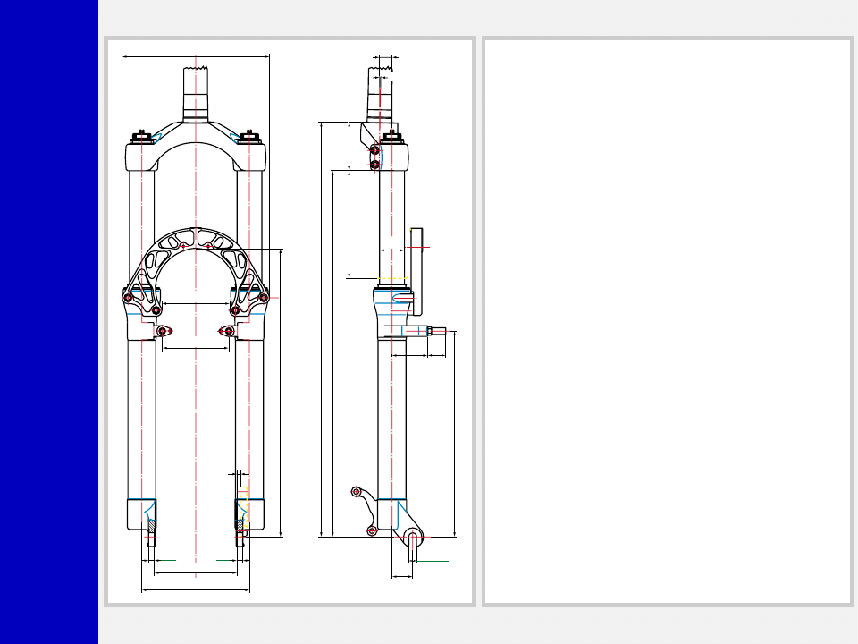
178
L.MAX=510.6
L.L.=500.6 L.MIN=370.6
TRA
VEL 130
248.5
9.2
58.5
15
Z1 CR MY2000 cod.10211000
25
130
100
6.8 6.8
+0.5
0
4
80
82
348
442.1
±
2
Ø30
43 22
1
°
GENERAL
• The fork is specifically designed for Downhill use and damped
by a coil spring and hydraulic cartridges.
• Rebound damping cartridge inside RH fork leg, compression
damping cartridge in LH fork leg.
• Spring pre-load and hydraulic damping adjustment controlled
via external top mount adjusters.
• Stanchion tubes feature full length 360º slider bushings giving
this fork an incredibly smooth stiction free stroke, in addition to
unmatched structural strength.
• Parts subjected to friction are cooled and lubricated by a
specially formulated oil.
• Stanchion tubes secured to crown so they will not become
separated accidentally.
Steer tube: in CrMo steel with variable butting. Several lengths
available in threaded and non threaded 1 1/8” diameters.
EASTON aluminum steer tubes available for 1 1/8”, threadless.
Crown: Forged and CNC-machined BAM
❊
aluminum alloy.
Arch: Forged and CNC-machined BAM
❊
aluminum alloy.
Stanchions: Anodized EASTON aluminum with variable butting.
Sliders: Cast and CNC-machined BAM
❊
aluminum alloy. Left
slider equipped with disc brake adapter.
Springs: Constant pitch springs.
Slider bushing: Full length guide bushing composed of a copper
base and impregnated with an anti-friction coating.
Seals: Computer designed oil seals guarantee the highest quality
seals available.
Oil: Specially formulated oil which eliminates foaming and viscos-
ity breakdown while providing complete stiction-free performance.
Fork leg oil: type EBH 16- SAE 7.5. 100 c.c.
❊
BAM: Bomber Aerospace Material.
Special alloy extracted from aerospace material.

Z1
C
R
GENERAL RULES FOR A
CORRECT OVERHAULING
AND MAINTENANCE
1. Where specified, assemble and disas-
semble the shock absorption system
using the MARZOCCHI special tools
only.
2. On reassembling the suspension sys-
tem, always use new seals.
3. If two screws are close one to the other,
always tighten using a 1-2-1 sequence.
In short, screw the first screw just up to
the point it is well tightened, then tighten
the second screw and then go back to
the first one and screw it tighter.
4. Clean all metal parts with a special,
preferably biodegradable solvent, such
as trichloroethane or trichloroethylene.
5. Before reassembling, lubricate all parts
in contact with each other using sili-
cone fat spray.
6. Always grease the conic seal rings
before reassembling.
7. Use wrenches with metric size only.
Wrenches with inch size might dam-
age the fastening devices even when
their size is similar to that of the wrenches
in metric size.
INSTRUCTIONS

Z1
C
R
FAILURES, CAUSES AND REMEDIES
This paragraph reports some troubles that may occur when using the fork. It also indicates possible causes and suggests a remedy.
Always refer to this table before doing any repair work.
Oil leaking through the bottom of slider
O-ring seal on the cartridge nut is dam-
aged
Replace the O-ring seal
Oil leaking through the top of slider
1. Oil seal is worn out
2. Stanchion tube is scored
3. Excessive dirt on slider oil seal
1. Replace oil seal
2. Replace oil seal and stanchion tube
3. Clean the oil seal seat and replace oil
seal
Fork has not been used for some time and
is locked out
Oil seals and dust seals tend to stick to
stanchion tube
Raise dust seal and lubricate stanchion
tube, oil seal and dust seal
Fork compresses and/or rebounds too fast
even though the adjuster is set to hardest
damping position
Cartridge is faulty
Replace hydraulic cartridge
Excessive play of stanchions into the sliders
Main slider bushings are worn
Replace main slider bushings
FAILURES
CAUSES
REMEDIES
Z1
C
R
RECOMMENDATIONS FOR
MAINTENANCE
MARZOCCHI forks are based on ad-
vanced technology, supported by year-
long experience in the field of profes-
sional mountain biking. In order to achieve
best results, we recommend to check and
clean the area below the dust seal and the
stanchion tube after each use and lubri-
cate with silicone oil.
Polished forks must be treated with body
work polish at regular intervals in order to
retain their finish.
INSTALLATION
Installing the Z1 fork on a bicycle is a very
delicate operation that should be carried
out with extreme care.
Always have the installation checked at
one of our Technical Service Centers.
WARNING: “A-Head Set” head-
set/Steer tube mounting and ad-
justment must be carried out in compli-
ance with the headset manufacturer’s in-
structions. Improper installation may jeop-
ardize the safety of the rider.
Be sure to install correct steer type, (A-
Head Set or threaded steer tube) diameter
and length for the frame on which it should
be fitted. The steer tube is an interference
fit in the crown and must be installed at
one of our Technical Service Centers who
have the proper equipment.
WARNING: In case of improper
installation of the steer tube into the
crown, the rider could lose control of his/
her bicycle, thus jeopardizing his/her
safety.
Check the torque of the bolts fastening the
stanchion tubes to the crown and those
securing the brake arch to the sliders at
regular intervals. Recommended torque is
11 Nm.
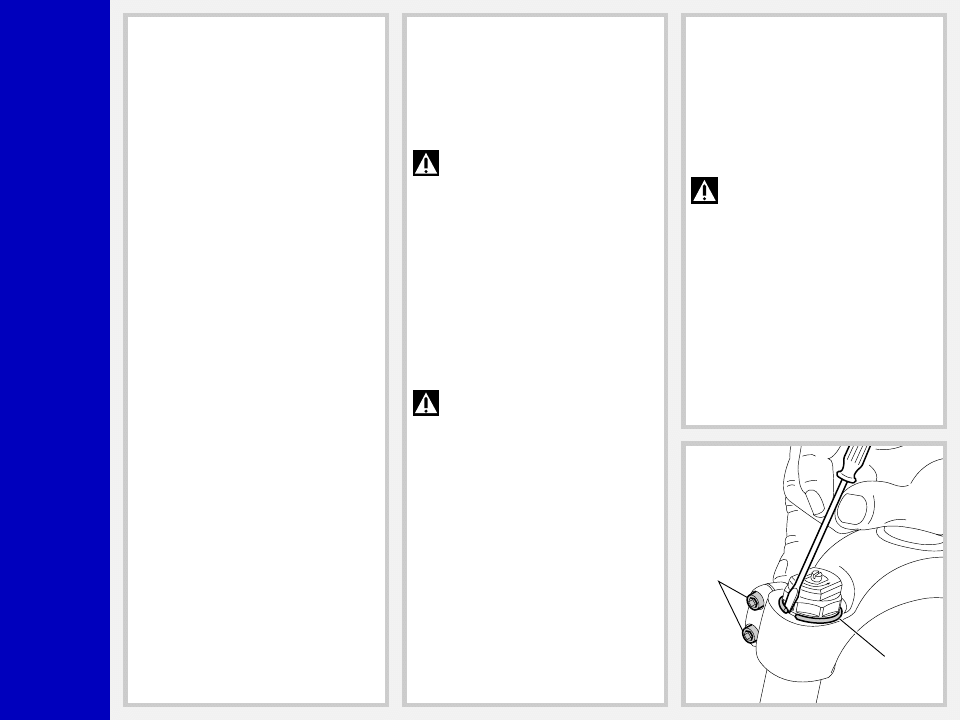
REMOVING THE FORK LEGS FROM
THE CROWN (Fig. A)
Installation procedure may require remov-
ing the fork legs from the slider. When this
is the case, loosen the screws (28) and slip
off the safety ring (30). Aid removal by
slipping a small screwdriver between ring
and cap. Remove the complete fork legs.
IMPORTANT: Be sure to refit the
safety rings into the fork legs upon
reassembly so that the fork legs will not
become separated from the crown in the
event the fastening bolts become loose
accidentally.
30
28

Z1
C
R
DISC BRAKE SYSTEM ASSEMBLY
Assembling the brake caliper onto the
slider is a very delicate operation that
should be carried out with extreme care.
Improper assembly might overstress the
caliper supports, which might break.
When installing the disc brake system, be
sure to properly follow the instructions
given by the manufacturer.
Z1
C
R
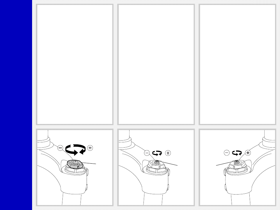
ADJUSTMENTS
SPRING PRELOAD (Fig. B)
The spring preload for COMPRESSION
damping can be adjusted by turning the
knob (2) on top of fork legs. From the
factory the Z1 fork is set with the minimum
preload, i.e. the adjustment knob is com-
pletely unscrewed counterclockwise. How-
ever, the spring is slightly preloaded to
help counteract static loads. By turning the
adjustment knob clockwise, the preload is
increased up to the maximum value equal
to 15 mm of spring preload. This adjust-
ment is essential in order to have the right
Z1 response for the rider weight and
riding style.
2
COMPRESSION DAMPING
ADJUSTMENT (Fig. C)
The l.h. fork leg is equipped with an
adjuster (C, BLACK) for COMPRESSION
damping adjustment. Turning this adjuster
clockwise into the cartridge rod, changes
the hydraulic setting of the inner valves. In
short, the amount of adjustment applied
on the piston in the fluid determines the
rate of compression damping.
To adjust, always start from the minimum
damping setting, i.e. unscrew completely
counterclockwise. About 8 turns - abt. 4
mm of the adjustment - are possible.
C
REBOUND DAMPING ADJUSTMENT
(Fig. D)
The r.h. fork leg features an adjuster (D)
for REBOUND damping adjustment. Ad-
justment and setting range are the same
as for the compression damping adjuster
(C) above.
D

Z1
C
R
▲
▲
▲
▲
▲
▲
▲
▲
▲
▲
▲
▲
▲
▲
▲
▲
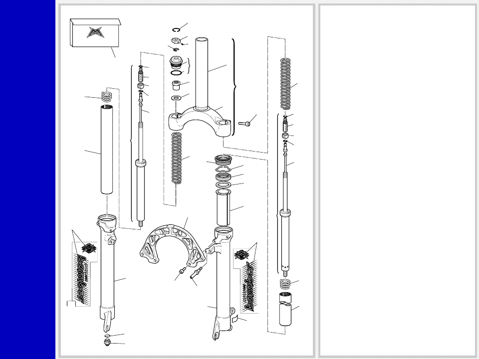
DISASSEMBLY
GENERAL
– The reference numbers given in this section relate to the components shown in the fork exploded view.
– Operations refer to the fork legs already removed from the crown and disassembled from the brake arch.
– Before starting any operation, please read the diagram below. It shows the quickest procedure and the exact disassembling
sequence. Start from the part to be disassembled and then follow the arrows to remove the other parts.
DISASSEMBLY DIAGRAM
STOP RING FIG. 2
STANCHION TUBE FIG. 7
DUST SEAL FIG. 8
SPRING FIG. 4
REBOUND SPRING FIG. 6
PRELOAD KNOB FIG. 1
HYDRAULIC CARTRIDGE
CHANGE
FOOT NUT FIG. 5
HYDRAULIC CARTRIDGE FIG. 6
GUIDE BUSHING AND SEAL
ASSEMBLY CHANGE
OIL SEAL FIG. 10
UPPER WASHER FIG. 11
GUIDE BUSHING FIG. 12
STANCHION TUBE CAP FIG. 3
SPRING CHANGE
STOP RING FIG. 9
FORK OIL CHANGE
Z1
C
R
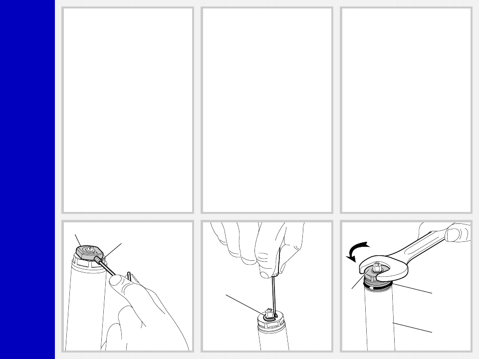
SPRING CHANGE
FIG. 1
Set the knob (2) to the minimum preload
position.
Loosen the grub screw (3) fastening the
preload knob (2) by means of a 1.5 mm
Allen wrench. Remove grub screw from
cap assembly.
FIG. 2
Remove the stop ring (4) from the top of the
preload knob support with a small screw-
driver.
FIG. 3
Place the stanchion tube (13) in a vice
making sure not to damage or dent it in the
process and unscrew the cap (5) with a 26
mm open end wrench.
Remove the cap complete with O-ring (6)
from the stanchion tube.
2
3
4
5
6
13
Z1
C
R
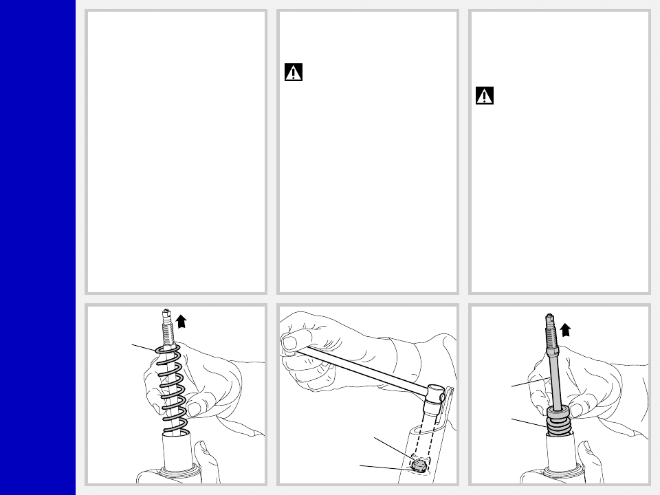
FIG. 4
Push the stanchion tube into the slider and
remove the spring (9).
Let all the oil drain into the fork leg. By
following this procedure, there is no need
to check the oil level. Make all necessary
changes.
9
17
18
11-29
12
HYDRAULIC CARTRIDGE CHANGE
FIG. 5
Let all the oil drain out.
WARNING: Remember to always
recycle any used oil.
To change the fork leg oil follow the
procedure as described in section
“REASSEMBLY” from FIG. 21 to FIG. 26.
Turn the fork leg upside-down and un-
screw the foot nut (18) complete with O-
ring (17) by the use of a 15 mm socket
wrench.
FIG. 6
Pull the hydraulic cartridge (11) or (29)
complete with rebound spring (12) out of
the stanchion tube.
Replace the whole hydraulic cartridge.
IMPORTANT: The hydraulic car-
tridge accommodated in the l.h.
fork leg controls COMPRESSION damp-
ing. You can tell it from the rebound
cartridge by the BLACK end and the holes
in cartridge casing.
Z1
C
R
GUIDE BUSHING AND SEAL
ASSEMBLY CHANGE
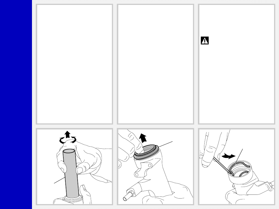
FIG. 7
Pull the stanchion tube (13) completely out
of the slider.
13
27
26
FIG. 8
Use a small screwdriver and remove the
dust seal (27) from the top of slider.
FIG. 9
Remove the stop ring (26) from the slider
by placing the screwdriver bit in one of the
three openings on the stop ring and care-
fully lifting the ring out of place.
IMPORTANT: when removing the
stop ring, make sure not to damage
its seat.

Z1
C
R
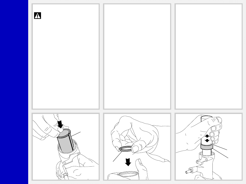
FIG. 10
Fit the slider protector (A) onto the slider
and remove the oil seal (25) with the help
of a large slot screwdriver.
IMPORTANT: when removing the
oil seal, make sure not to damage
its seat. Once removed the oil seals should
not be used again.
25
A
24
23
FIG. 11
Remove the upper washer (24) from the
slider.
FIG. 12
Fit the bit of a small screwdriver into the
upper edge slot of the guide bushing (23)
and lift gently. Pull the bushing out of the
slider and make all necessary changes.
Z1
C
R
REASSEMBLY
CAUTION: before reassembling,
all metal components should be
washed carefully with inflammable and
biodegradable solvent and dried with
compressed air.
GUIDE BUSHING AND SEAL
ASSEMBLY
FIG. 13
Check that no dirt or debris is between
slider and bushing. Insert the guide bush-
ing (23) into place so that it adheres to the
slider.
23
24
25
B
FIG. 14
Fit the upper washer (24) into the slider so
that it touches the guide bushing.
FIG. 15
Lubricate the oil seal (25) and place it onto
the seal press (B) with the hollow side
toward the slider.
Press the oil seal into place until it touches
the upper washer by using the above seal
press.

Z1
C
R
FIG. 16
Insert the stop ring (26) making sure it is
properly seated into place in the slider.
26
13
27
STANCHION TUBE
FIG. 17
Fit the stanchion tube (13) gently into the
dust seal, from the non threaded end.
Rotate the stanchion tube while inserting it
into the seal to facilitate installation and
reduce the chance of damaging the seals.
Check to see that the stanchion tube slides
unrestricted by cycling the fork up and
down several times. The tube should slide
freely inside the seal assembly without
any side play. In the event it is too hard or
too soft, repeat the previous steps de-
scribed above and check components to
ensure they are not damaged.
FIG. 18
Lubricate the dust seal (27) and fit it into its
seat in the stanchion.
Fit it into the slider seat.
Z1
C
R
HYDRAULIC CARTRIDGE
FIG. 19
Fit the rebound spring (12) into the hy-
draulic cartridge. Insert the complete hy-
draulic cartridge (11) or (29) with the
stanchion pressed fully down into the
slider.
IMPORTANT: The cartridge with
the BLACK adjuster goes into the
l.h. fork leg.
11-29
12
17
18
Nm
12
50
FIG. 20
Grease the O-ring (17) on the foot nut (18)
and screw the nut on the hydraulic car-
tridge threaded end.
Tighten to 12 Nm.
Pump stanchion up and down several
times to make sure it slides properly through
the stroke.
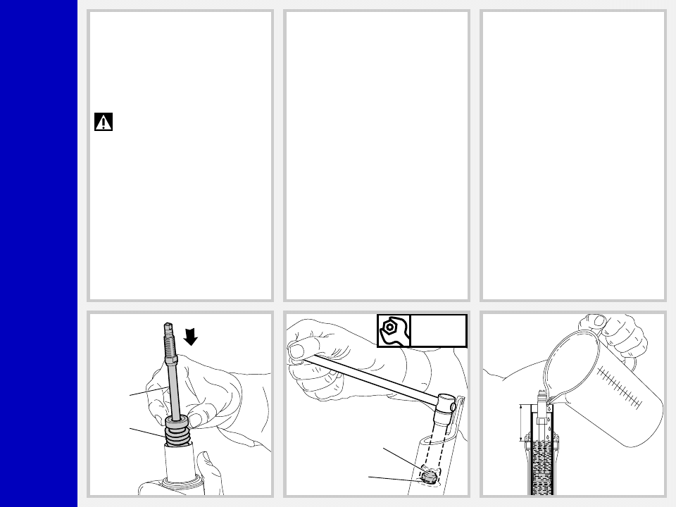
HOW TO FILL WITH OIL
FIG. 21
Pour the oil little by little when the stan-
chion tube is fully down and then pump
with the cartridge (11) or (29) rod so as to
have a better filling. Cartridge is full when
no air is detected when pumping, in the
fully compressed position.
Check that the oil level is 50 mm/1.97 in.
from the top of the stanchion tube in each
leg.

Z1
C
R
SPRING AND CAP
FIG. 22
Fit the spring (9) into the stanchion tube.
Lubricate the O-ring (10) on the top of the
preload knob support and the O-ring (6)
on the cap (5).
9
10
6
8
5
11-29
5
Nm
12
FIG. 23
Move the plunger (7), in the cap, to the
minimum preload position.
Screw the cap (5) complete with lower
washer (8) onto the cartridge (11) or (29)
rod. Screw cap all the way in.
FIG. 24
Take the stanchion tube and fit the cap (5)
by hand. Place the stanchion tube in a vice
making sure it is not damaged or dented
in the process and tighten the cap to 12
Nm.

Z1
C
R
FIG. 25
Fit the stop ring (4) of the preload knob
support and make sure it is properly
seated into place.
4
FIG. 26
Fit the preload knob (2) and secure it on
the support by tightening the grub screw
(3) to 1.5 Nm.
Fit the brake arch to the fork leg, and then
install fork legs into crown as specified in
section “INSTALLATION”.
Nm
1,5
2
3

Z1
C
R
SPECIFIC TOOLS
Ref.
Item.
Description and use
A
536003 AB
Slider protector: to remove the oil seal from the slider
B
R 5068
Oil seal press: to press oil seal into the slider
B
A
Wyszukiwarka
Podobne podstrony:
2000 z1 x fly
2000 z1 qr20
2000 z1 drop off
CR 12101-5 V 2000, NORMY(hasło NORMY)
Wyklad1 bilans BK dzienne zaoczne cr (1)
03 2000 Revisions Overview Rev 3 1 03
Wyklad13 efektywnosc cr (1)
Natura 2000
brzuch 1999 2000
MAZDA B3000 2000
zlotnik jubiler 731[06] z1 04 u
mechanik pojazdow samochodowych 723[04] z1 04 n
koszykarz plecionkarz 742[02] z1 01 n
lakiernik 714[03] z1 04 n
więcej podobnych podstron