Service Source
K
StyleWriter
Service Source
K
Basics
StyleWriter
Basics
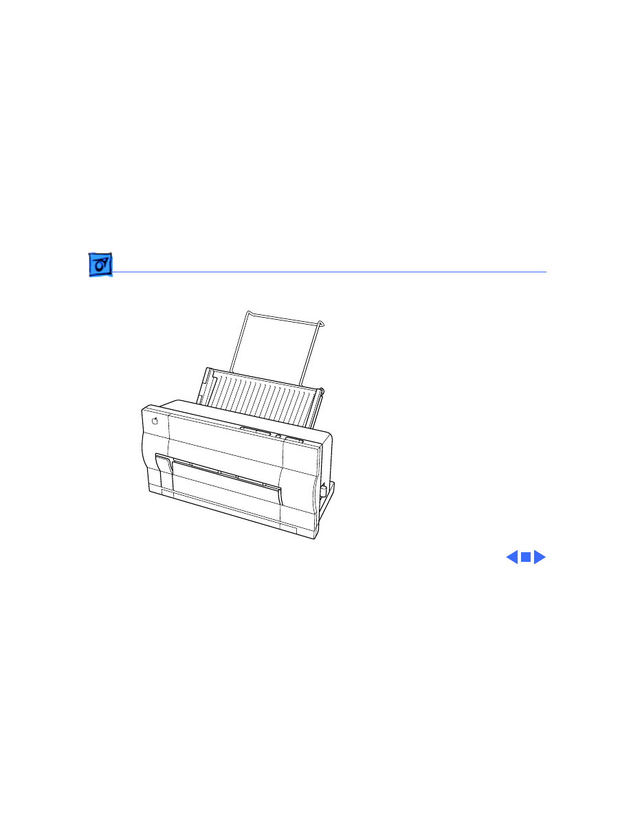
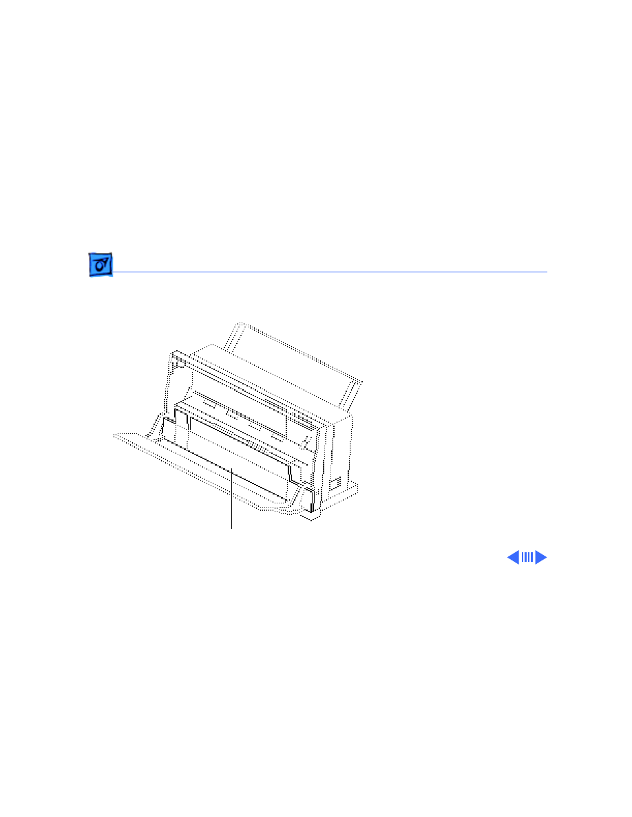
Introduction - 1
Introduction
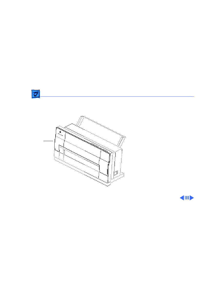
The StyleWriter is a serial
bubble jet ink-on-demand
printer.
The StyleWriter prints up
to 1/3 page per minute at a
resolution of 360 dpi in
Best Mode.
Service Source
K
Specifications
StyleWriter

Specifications
Characteristics - 1
Characteristics
Print Methods
Serial bubble jet ink-on-demand
Throughput
1/3 page per minutes in Best mode
1/2 page per minute in Faster mode
(actual speed depends on images printed)
Print Head
1 by 64 nozzles
Print Head Life
Approximately 500 pages (normal mode)
Input Buffer
8 K

Specifications
Graphics - 2
Graphics
Resolution
360 dpi (Best mode)
180 dpi (Faster mode)

Specifications
Paper Handling - 3
Paper Handling
Paper
Size: LTR, LGL, A4
Weight: 16-24 lb.
Capacity: 50 sheets (A4, LTR)
Envelopes
Size: Commercial number 10 size only (4.1 in. by 9.5 in)
Transparencies
Coated transparencies, or most inkjet transparencies

Specifications
Ink Cartridges - 4
Ink Cartridges
Type
Ink cartridge
Ink Color
Black
Ink Amount
Approximately 20 g (per cartridge)
Life
Approximately 500 pages

Specifications
Environmental - 5
Environmental
Acoustic Noise Level
Under 50 dB (reference level)
Temperature
59-86° F (15-30° C )
Humidity
20-70% (no condensation)

Specifications
Electrical - 6
Electrical
Power Source
U.S./Canada: 120 VAC, 60 Hz
Japan: 120 VAC, 50/60 Hz
U.K./Australia: 240 VAC, 50 Hz
Europe: 220 VAC, 50 Hz
Power Consumption
23 W maximum at 120 V
25 W maximum at 220 V

Specifications
Physical - 7
Physical
Dimensions
Height: 12.5 in. (32 cm)
Width: 13.25 in. (33.6 cm)
Depth: 9 in. (23 cm)
Weight
Approximately 7.5 lb. (3.4 kg)

Service Source
K
Troubleshooting
StyleWriter

Troubleshooting
General/ - 1
General
The Symptom Charts included in this chapter will help you
diagnose specific symptoms related to your product. Because cures
are listed on the charts in the order of most likely solution, try
the first cure first. Verify whether or not the product continues to
exhibit the symptom. If the symptom persists, try the next cure.
(Note: If you have replaced a module, reinstall the original module
before you proceed to the next cure.)
If you are not sure what the problem is, or if the Symptom Charts
do not resolve the problem, refer to the Flowchart for the product
family.
For additional assistance, contact Apple Technical Support.

Troubleshooting
Symptom Charts /Preliminary Checks - 2
Symptom Charts
Preliminary Checks
Computer cannot find
printer
1 Verify that StyleWriter drive is installed.
2 Verify that Chooser and Control Panel settings are correct.
3 Verify that serial cable is connected.
4 Replace serial cable.
No lights or
movement
1 Verify that printer is turned on and plugged into power
adapter and wall socket.
2 Replace AC power adapter.
3 Replace 2.5 amp fuse on logic board.

Troubleshooting
Symptom Charts /Preliminary Checks - 3
Print quality
problems
1 Verify that paper is correct weight.
2 Purge ink cartridge.
3 Replace ink cartridge.
4 Verify that logic board and printer frame are compatible
with StyleWriter revision. See “Revision Identification” in
Additional Procedures.
Mechanical problems
1 Verify that paper is correct weight.
2 Clear paper jam.
3 Verify that cut sheet feeder aligns with printer.
4 Replace cut sheet feeder.

Troubleshooting
Symptom Charts /Status Light - 4
Status Light
No status lights
1 Check AC adapter connection.
2 Replace AC adapter.
3 Replace fuse.
4 Verify that operation cable is securely connected to logic
board.
5 Replace logic board.
6 Replace operations panel assembly.
7 Replace operations panel cable.
Error and power
lights blink; ready
light is off
1 Carriage is jammed. Remove anything that obstructs free
motion of carriage.
2 Replace logic board.
3 Verify that paper sensor is seated correctly.
4 Replace printer frame assembly.
5 Replace operations panel assembly.
6 Replace operations panel cable.

Troubleshooting
Symptom Charts /Status Light - 5
Error light blinks;
power light is on,
ready light is off
1 Close front cover.
2 Verify that paper is inserted properly.
3 Check for paper jam; remove jam, then press ready switch.
If ready and power lights come on steadily and error light is
off, problem is resolved.
4 Replace paper sensor.
5 Replace logic board.
6 Replace printer frame assembly.
7 Replace operations panel assembly.
8 Replace operations panel cable.
Error, power, and
ready lights blink
1 Check cables.
2 Replace logic board.

Troubleshooting
Symptom Charts /Printing - 6
Printing
No printing
1 Verify that interface cable between printer and computer is
tightly connected.
2 Make sure printer is selected in Chooser.
3 Purge ink cartridge.
4 Replace ink cartridge.
5 Replace paper sensor.
6 Replace logic board.
7 Verify that paper sensor is seated correctly.
8 Replace printer frame assembly.

Troubleshooting
Symptom Charts /Printing - 7
Garbled printing
1 Verify that interface cable between printer and computer is
tightly connected.
2 Purge ink cartridge.
3 Replace ink cartridge.
4 Verify that logic board and printer frame are compatible
with StyleWriter revision. See “Revision Identification” in
Additional Procedures.
5 Replace logic board.
6 Replace printer frame assembly.
Overprinting
1 Verify that program being used is set for correct line
spacing and line length.
2 Verify that correct printer driver is installed.
3 Replace logic board.
4 Replace printer frame assembly.

Troubleshooting
Symptom Charts /Printing - 8
Image too light or too
dark
1 Purge ink cartridge.
2 Use 16 lb. to 24 lb. cotton bond paper.
3 Verify that forms thickness lever is set correctly (up for
standard paper; down for envelopes, transparencies, labels,
and heavy paper).
4 Replace ink cartridge.
White lines in
printing
1 Purge ink cartridge.
2 Replace ink cartridge.
3 Replace logic board.
4 Replace printer frame assembly.

Troubleshooting
Symptom Charts /Printing - 9
Page prints off
center; images are out
of place
1 Use 16 lb. to 24 lb. cotton bond paper.
2 Verify that sheet feeder holds no more than 50 sheets.
3 Verify that paper is inserted properly.
4 Verify that margins in document and paper size in Page Setup
are set correctly.
5 Replace logic board.
6 Replace printer frame assembly.
Ink appears on back of
paper
1 Clean platen with soft, dry cloth.
2 Clean platen rollers.
3 Replace platen rollers.
4 Replace printer frame assembly.
Image wavy, splotchy,
or distorted
1 Purge ink cartridge.
2 Replace ink cartridge.
3 Replace printer frame assembly.

Troubleshooting
Symptom Charts /Carrier Movement - 10
Carrier Movement
Erratic carrier
motion
1 Replace logic board.
2 Replace printer frame assembly.
Power light is on;
carrier does not move
1 Make sure carrier area is clear of obstructions.
2 Replace logic board.
3 Replace printer frame assembly.
Printer does not
perform self-test;
ready light is on
1 Replace logic board.
2 Replace operations panel assembly.
3 Replace printer frame assembly.
Carrier grinds, hums
loudly, or locks
1 Verify that paper sensor is seated correctly.
2 Replace printer frame assembly.

Troubleshooting
Symptom Charts/Paper Feed - 11
Paper Feed
No paper feed
1 Verify that cut sheet feeder aligns with printer.
2 Release paper pressure plate on cut sheet feeder.
3 Make sure paper path is clear of obstructions.
4 Replace cut sheet feeder.
5 Replace logic board.
6 Replace printer frame assembly.
Grinding during paper
feed
1 Make sure paper path is clear of obstructions.
2 Verify that forms thickness lever is set correctly (up for
standard paper; down for envelopes, transparencies, labels,
and heavy paper).
3 Verify that cut sheet feeder aligns with printer.
4 Replace cut sheet feeder.
5 Replace logic board.
6 Replace printer frame assembly.

Troubleshooting
Symptom Charts /Paper Feed - 12
Paper feed
difficulties: binding,
tearing
1 Verify that forms thickness lever is set correctly (up for
standard paper; down for envelopes, transparencies, labels,
and heavy paper).
2 Make sure paper path is clear of obstructions.
3 Verify that paper is inserted properly.
4 Use 16 lb. to 24 lb. cotton bond paper.
5 Verify that cut sheet feeder aligns with printer.
6 Replace cut sheet feeder.
7 Replace printer frame assembly.
Envelope feed
problems
1 When printing envelopes
• Adjust paper thickness lever
• Do not run cut sheets and envelopes in same print job
• Reset paper thickness lever after printing envelopes
2 Replace printer frame assembly.

Troubleshooting
Symptom Charts /Miscellaneous - 13
Miscellaneous
Operations panel
buttons don’t work
1 Verify that operations panel cable is securely connected to
logic board and operations panel.
2 Replace logic board.
3 Replace operations panel cable.
4 Replace operations panel.
Software-specific
problem
1 Verify that software is known-good.
2 Verify that software is compatible with TrueType fonts.
(Check your software application manual.)

Service Source
K
Take Apart
StyleWriter
Take Apart
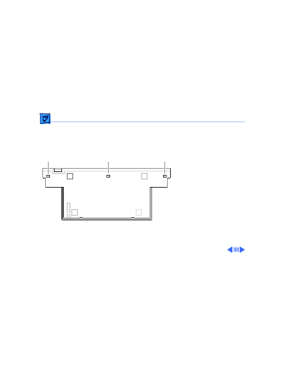
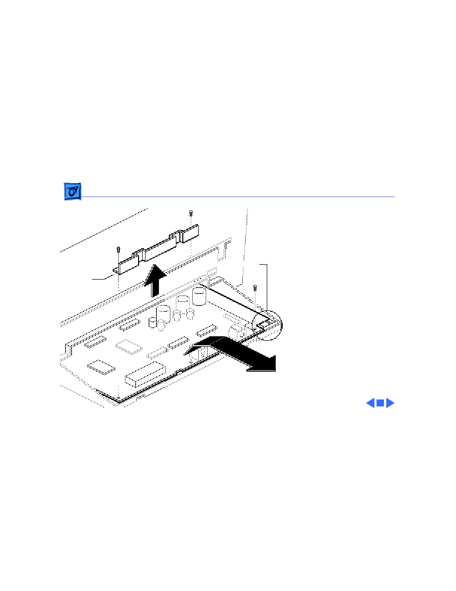
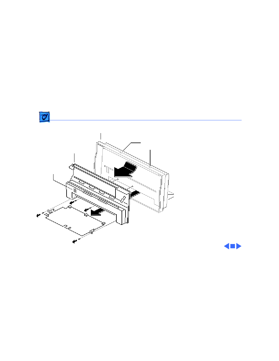
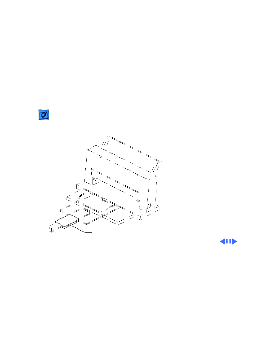
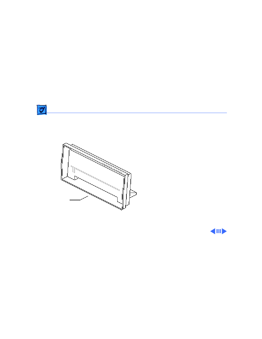
Lower Access Cover - 1
Lower Access
Cover
No preliminary steps are
required before you begin
this procedure.
Caution:
To ensure the print
head is capped, switch off
the StyleWriter before
unplugging it.
Lower Access Cover
Take Apart
Lower Access Cover - 2
Caution:
Be careful not to
bend or break any of the
plastic tabs on the
StyleWriter. Use jeweler’s
screwdrivers and precision
tweezers and do not apply
excessive force.
Note:
Before taking apart
the StyleWriter, remove the
ink cartridge and separate
the printer from the cut
sheet feeder.
1 Using a small flat-blade
screwdriver, release the
three tabs along the
bottom of the rear cover.
Tab
Tab
Tab
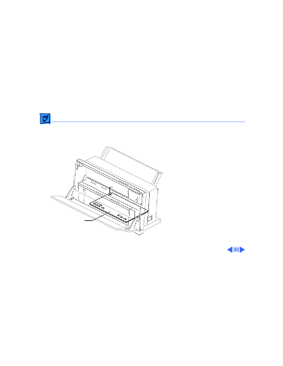
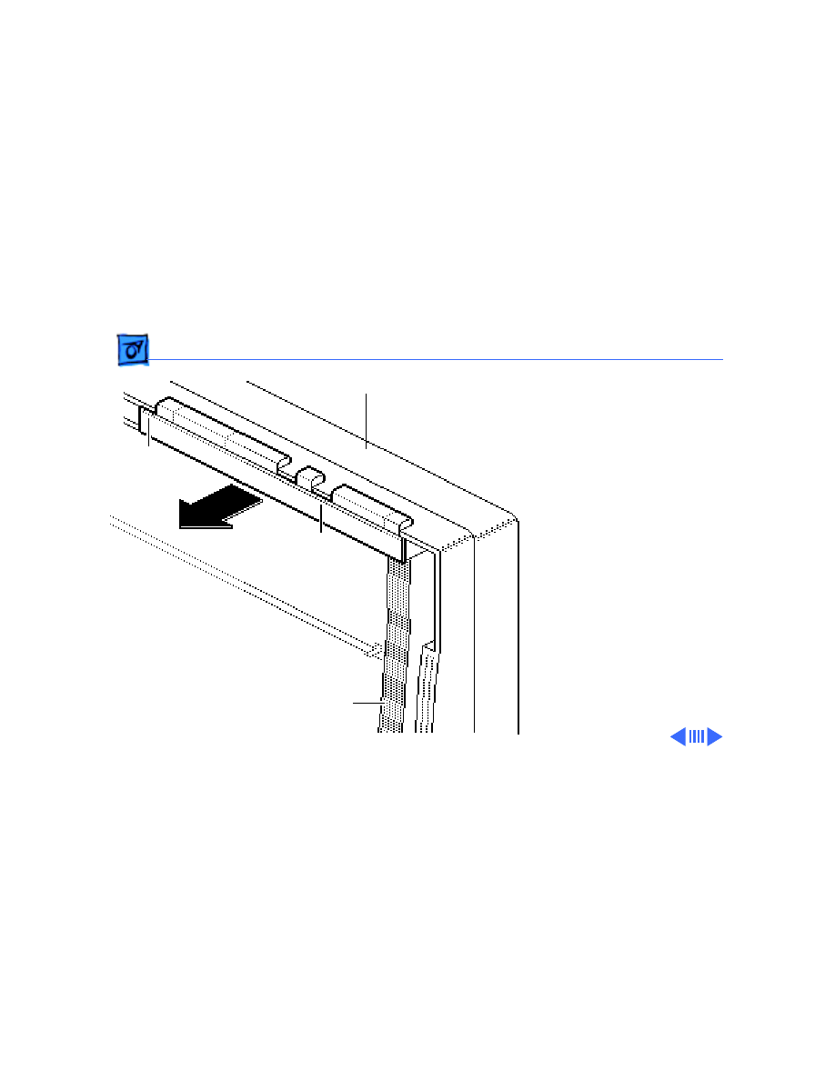
Take Apart
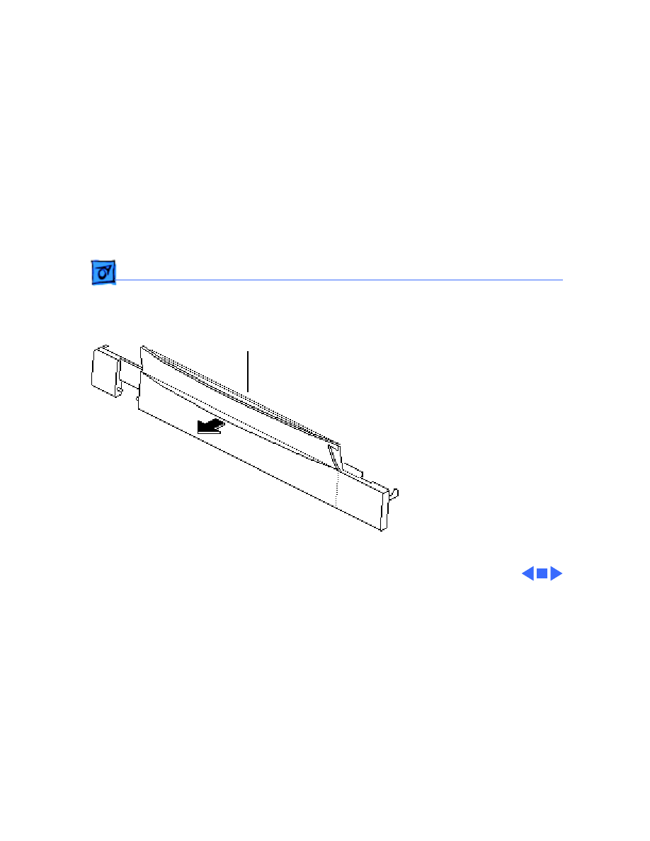
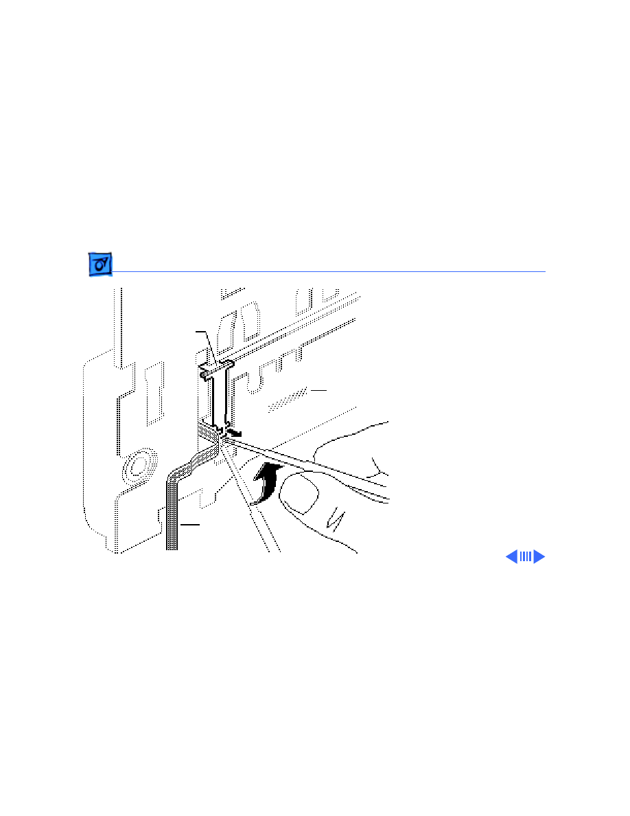
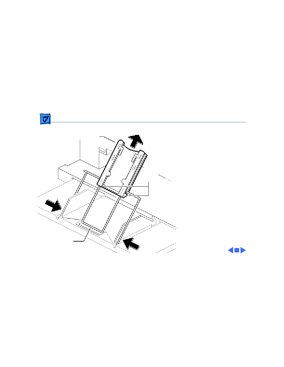
Lower Access Cover - 3
2 Pry the paper release
lever away from the
lower access cover and
snap it free from the
holding knobs.
3 Twist and slip the lever
off the paper release
post on the frame.
Holding Knobs
Paper Release Post
Paper Release Lever
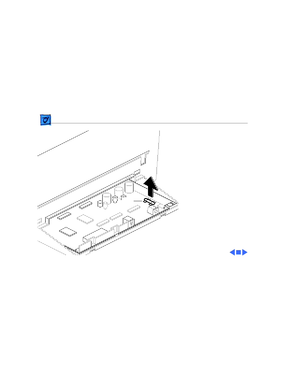
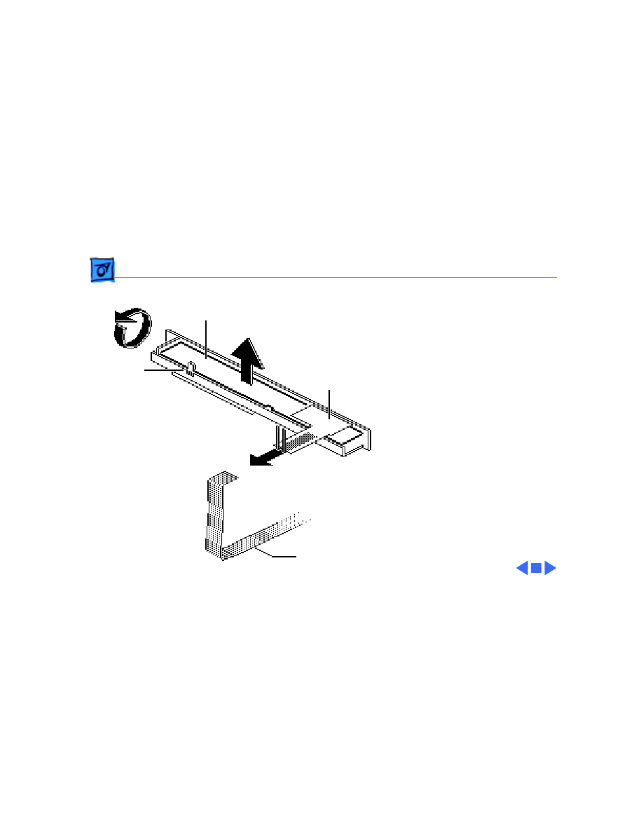
Take Apart
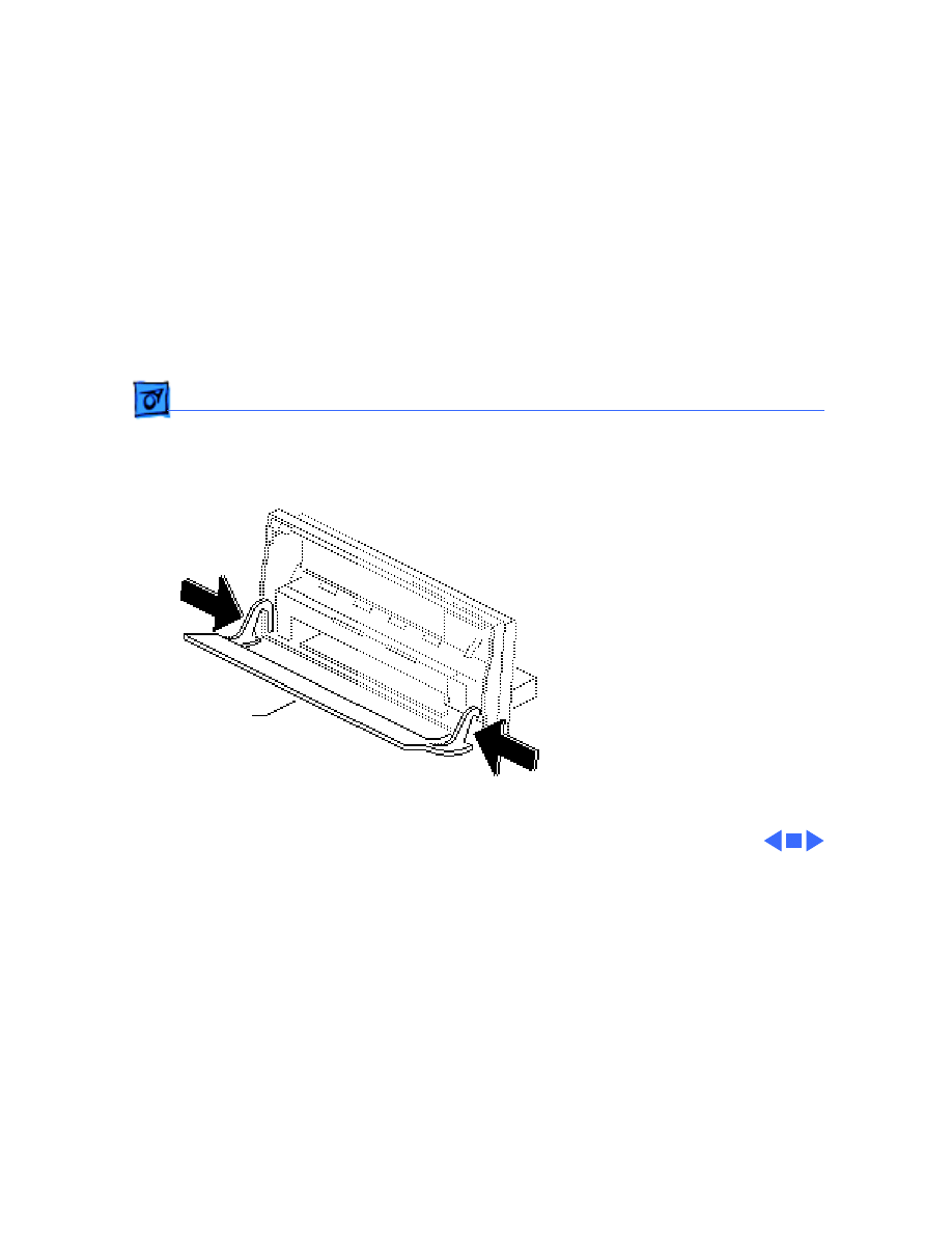
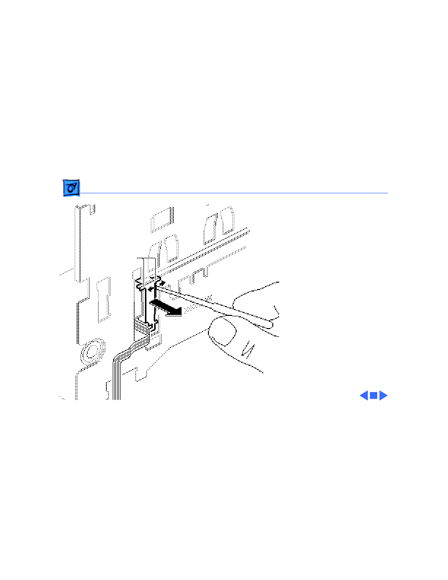
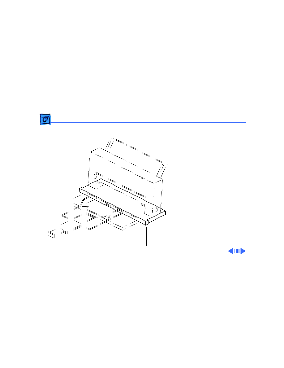
Lower Access Cover - 4
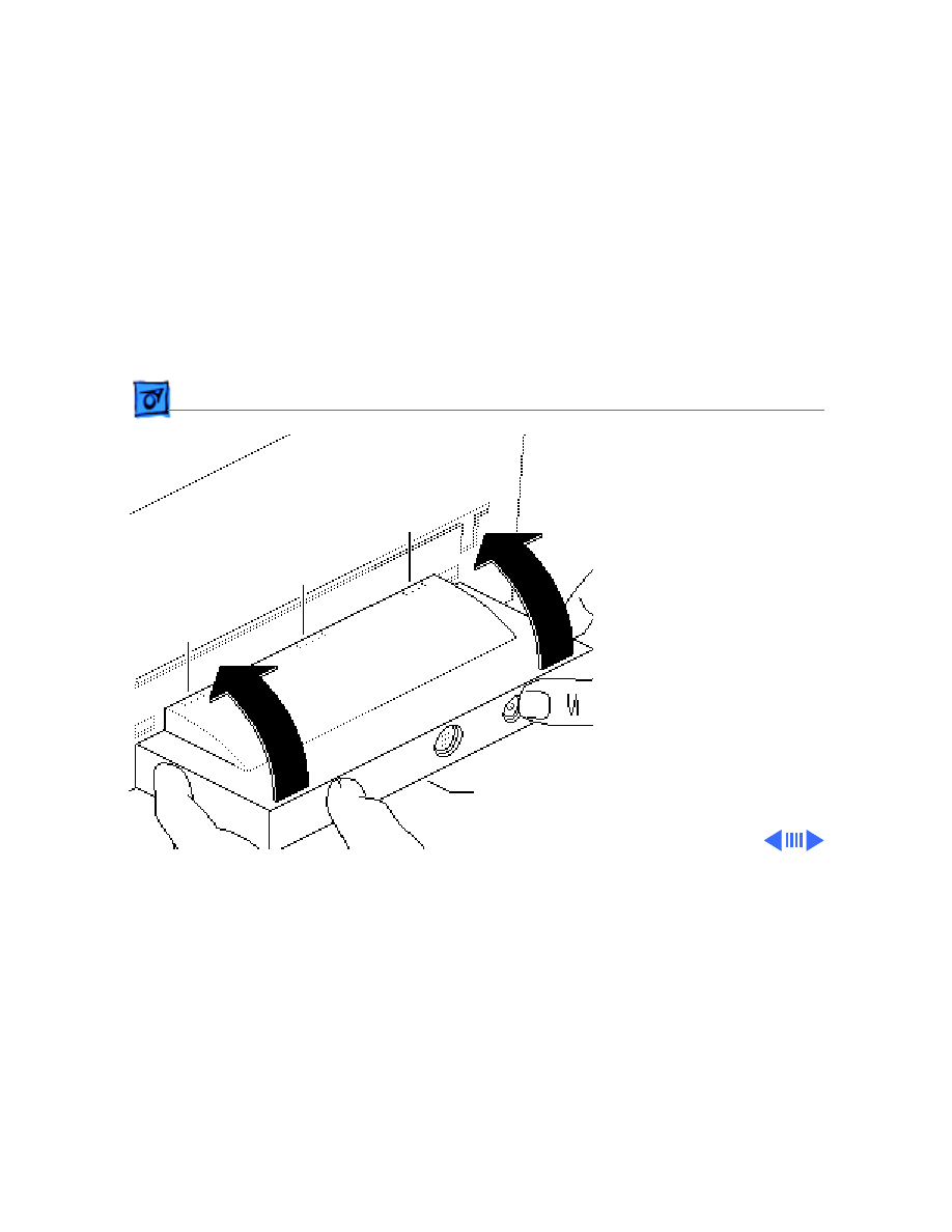
4 Open the upper access
cover.
5 Free the lower access
cover at the upper tabs.
6 Remove the lower access
cover.
Left Upper
Right Upper
Tab
Tab
Take Apart
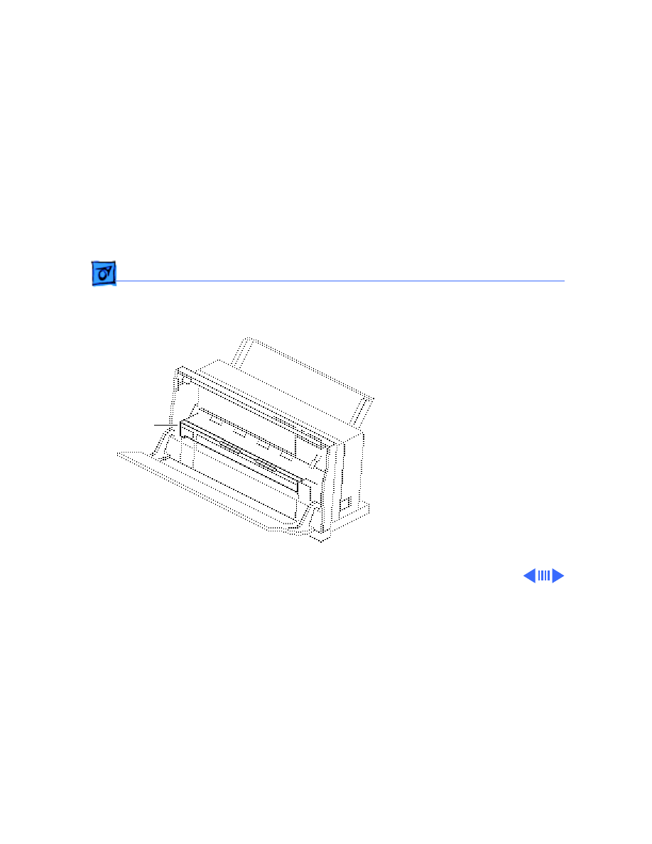
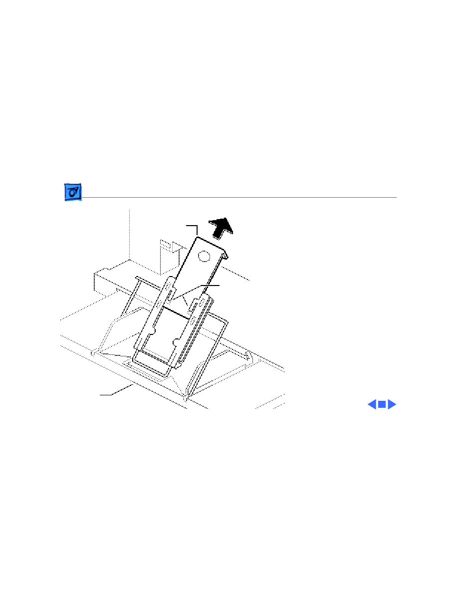
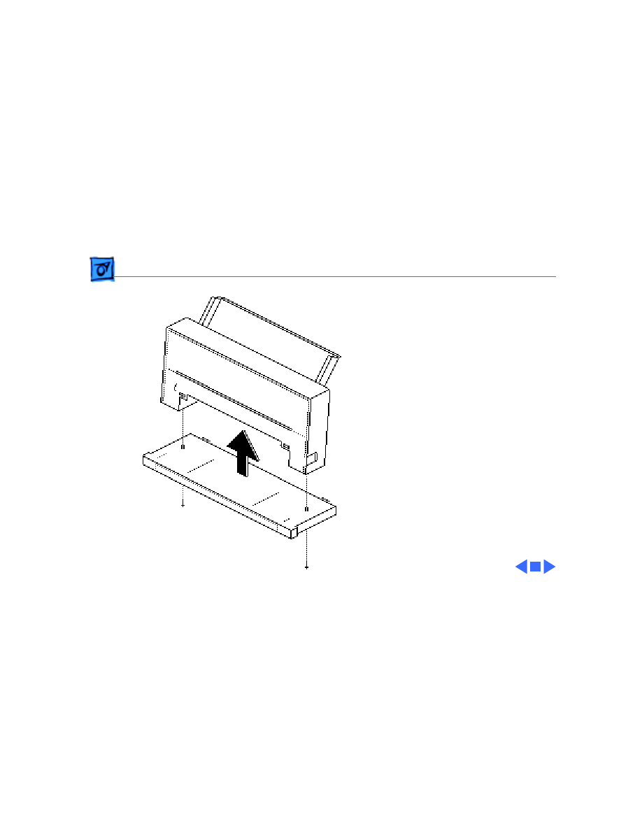
Lower Access Cover - 5
7 Remove the manual feed
tray by flexing it
enough to free the plastic
hinges from the lower
access cover.
Manual Feed Tray

Take Apart
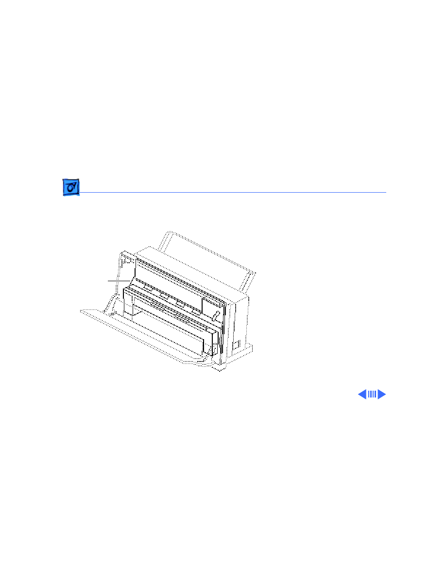
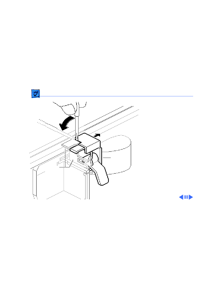
Front Access Cover - 6
Front Access
Cover
Before you begin, remove
lower access cover.
Note:
The front access cover
is held in place by two arms
that function as hinges.
Plastic knobs at the end of
the arms fit into holes on the
inside of the rear cover.
Front
Cover
Access
Take Apart
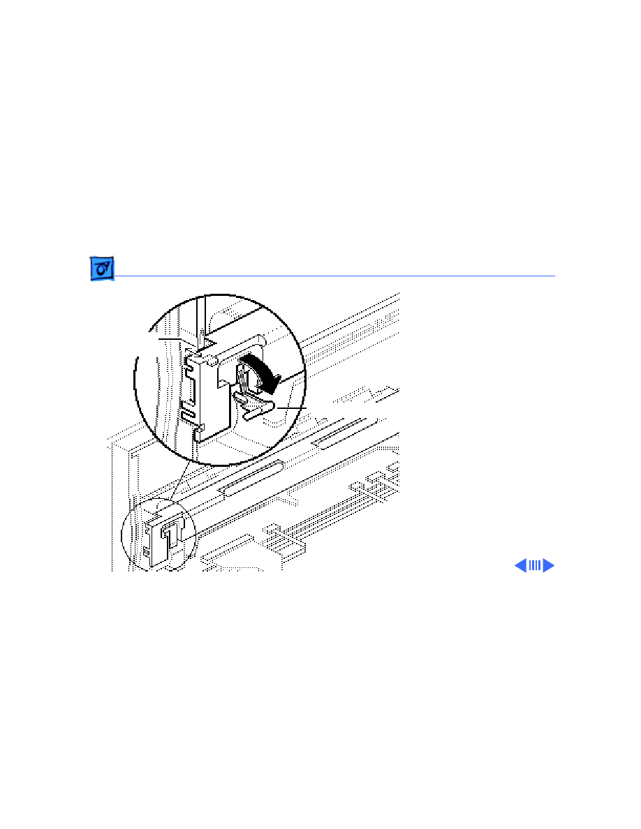
Front Access Cover - 7
1 Open the front access
cover.
2 Press the end of each
arm inward and free the
arm’s knob from the
hole in the rear cover.
3 Lift off the front access
cover.
Front
Cover
Access
Take Apart
Platen Cover and Rollers - 8
Platen Cover and
Rollers
Before you begin, remove
the following:
• Lower access cover
• Front access cover
Caution:
Remove the platen
cover only if it is broken and
must be replaced. Do not
remove it to perform other
take–apart procedures. The
plastic tabs are hidden and
tiny, and they break easily.
Do not use force!
Platen Cover
and Rollers
Take Apart
Platen Cover and Rollers - 9
1 Pull the paper release
post down as far as
possible.
2 Using a jeweler’s
screwdriver, carefully
free the upper left tab.
Upper Left
Paper Release Post
Tab Release
Take Apart
Platen Cover and Rollers - 10
3 Using a jeweler’s
screwdriver, gently pry
between the platen
cover and printer frame
and free the lower left
tab release.
4 Lift and twist the cover
to free the right tab
release.
5 Lift the platen cover
free.
Right Tab
Release
Lower
Left Tab
Release
Take Apart
Platen Cover and Rollers - 11
6
Note:
It is not necessary
to remove the platen
cover from the printer
frame to remove a
roller.
To remove a roller,
grasp one end, press
firmly to the side, and
snap the roller out of the
mounting holes.
Roller
Platen
Cover

Take Apart
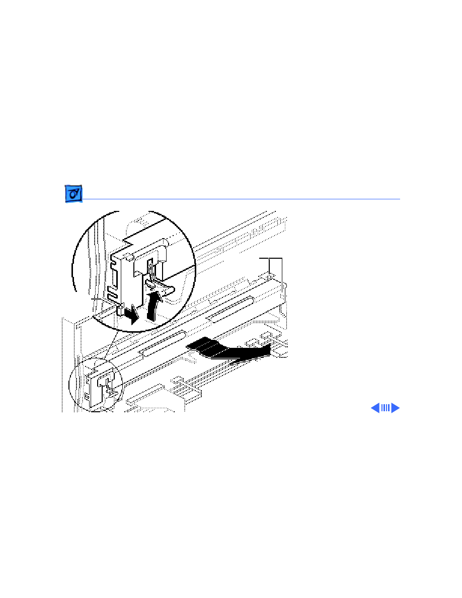
Logic Board - 12
Logic Board
Before you begin, remove
the following:
• Lower access cover
• Front access cover
Review the ESD precautions
in Bulletins/Safety.
Caution:
You must replace
Revision A and Revision B
logic boards like-for-like.
If you are replacing the logic
board, see “Revision
Identification” in Additional
Procedures.
Logic Board

Take Apart
Logic Board - 13
1 Using a small flat-blade
screwdriver, gently pry
up and release the two
tabs on the bottom of the
printer.
Tab
Tab
Take Apart
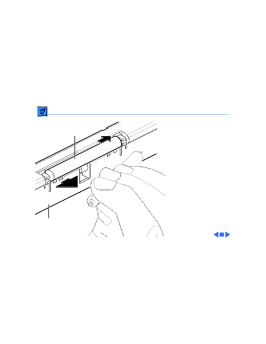
Logic Board - 14
2 Lift the rear of the logic
board cover and release
it at the forward tabs.
Forward
Logic Board
Cover
Tab
Forward
Tab
Forward
Tab
Take Apart
Logic Board - 15
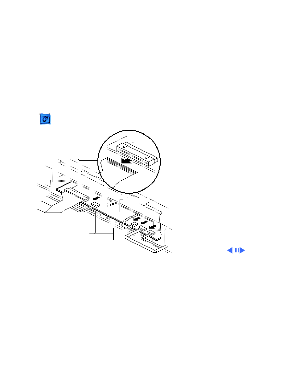
3
Caution:
Disconnect the
five ribbon cables with
great care and only
when necessary.
Turn the printer around
so that you see the
printer frame assembly.
4 Gently pull on the tab
ends of the four smaller
ribbon cables, and
disconnect them from the
logic board.
5 Slide the front half of the
largest connector
toward you into the
unlocked position. Gently
pull out the cable.
Large Ribbon
Small Ribbon
Logic Board
Connector
Connector
Take Apart
Logic Board - 16
6 Remove the three screws
and set aside the EMI
fence.
7 Slide the logic board out
of the frame from the
rear. Be sure to keep the
retainer clip.
EMI
Retainer
Fence
Clip
Take Apart
Fuse - 17
Fuse
Before you begin, remove
the following:
• Ink Cartridge
• Cut Sheet Feeder
Review the ESD precautions
in Bulletins/Safety.
Logic Board
Fuse

Take Apart
Fuse - 18
1 Using a small flat-blade
screwdriver, gently pry
up and release the two
tabs on the bottom of the
printer.
Tab
Tab

Take Apart
Fuse - 19
2 Lift the rear of the logic
board cover and release
it at the forward tabs.
Forward
Logic Board
Cover
Tab
Forward
Tab
Forward
Tab
Take Apart
Fuse - 20
3 Using a jeweler’s
screwdriver, gently pry
the ends of the fuse out of
the holder.
Fuse
Take Apart
Printer Frame Assembly - 21
Printer Frame
Assembly
Before you begin, remove
the following:
• Lower access cover
• Front access cover
• Logic board
Note:
The printer frame
assembly comes with the
platen cover, paper sensor,
cartridge hook, and forms
thickness lever installed.
Do not remove these parts
prior to returning a
printer frame to Apple.
Printer Frame
Assembly

Take Apart
Printer Frame Assembly - 22
Caution:
You must replace
Revision A and Revision B
printer frame assemblies
like-for-like. If you are
replacing the frame
assembly, see “Revision
Identification” in Additional
Procedures.
Printer Frame
Assembly
Take Apart
Printer Frame Assembly - 23
1 Remove the four screws.
2 Slide the RFI shield out
the front of the printer.
3 Pull the printer frame
assembly down and out
and free it from the
release tabs.
Replacement Note:
Ribbon cables on
replacement printer
frame assemblies are
taped to the assembly for
shipping. Remove the
tape carefully and press
the cartridge ribbon
cable onto the double-
stick tape.
Rear Cover
Release
Tabs
Printer Frame
Double-Stick
Assembly
Tape
(Rear Side)

Take Apart
Operations Panel Assembly - 24
Operations Panel
Assembly
Before you begin, remove
the following:
• Lower access cover
• Front access cover
• Logic board
• Printer frame assembly
Note
: The operations panel
assembly includes the panel
cover (with buttons) and the
PCB. The metal shield and
the operations panel cable
are available separately.
Control Panel
Assembly
Operations Panel
Assembly
Take Apart
Operations Panel Assembly - 25
1
Note
: The ribbon cable is
attached to the inside of
the rear cover with
double-stick tape.
Carefully pull up on the
ribbon cable.
2 Using a jeweler’s
screwdriver, depress
the two tabs.
3 Slide the operations
panel toward you and
free it from the rear
cover.
Printer Rear Cover
Ribbon Cable
Tab
Release
Point
Tab
Release
Point
Take Apart
Operations Panel Assembly - 26
4 To remove the operations
panel cable, pull gently
on the cable connector
and free it from its
connector.
5 To remove the metal
shield, release the tab
and lift out the board and
the metal shield.
Replacement Note:
When replacing the
operations panel cable,
be sure the metal teeth
of the ribbon cable face
the bottom side of the
connector and that the
colored plastic faces up.
Metal Shield
Board
Tab
Operations Panel
Cable

Take Apart
Cartridge Hook - 27
Cartridge Hook
Before you begin, remove
the following:
• Lower access cover
• Front access cover
• Logic board
• Printer frame assembly
Caution:
Place the printer
frame assembly on a padded
surface, taking care not to
crumple the ribbon cables
under the frame.
Note:
The cartridge hook kit
contains the cartridge hook,
lever, spring, and holder.
Cartridge
Hook
Take Apart
Cartridge Hook - 28
1 Using a jeweler’s
screwdriver, gently pry
between the top of the
cartridge hook holder
and the adjacent plastic
of the cartridge carrier.
2 Push the cartridge hook
holder slightly away
from the cartridge
carrier.
Cartridge
Carrier
Cartridge
Hook
Holder
Take Apart
Cartridge Hook - 29
3 Using small needlenose
tweezers, gently squeeze
the tips of the lower tabs
inward and release the
spring that holds the
lever in position.
Lever
Lower
Tabs
Take Apart
Cartridge Hook - 30
4
Note:
The four pieces of
the cartridge hook
assembly (the holder,
spring, lever, and hook)
will fall into your hand
when you perform this
step.
Pull the cartridge hook
holder off the frame.
Carriage Hook
Lever
Spring
Carriage Hook Holder

Take Apart
Cartridge Hook - 31
Replacement Note:
To
reassemble, put the
cartridge hook on its
post on the cartridge
carrier, and put the blue
lever and spring over
the central post of the
holder. Slide the
assembly into place as
you mesh the ridge on
the lever with the groove
on the bottom of the
cartridge hook. Snap the
assembly securely into
place.
Carriage Hook
Lever
Spring
Carriage Hook Holder

Take Apart
Forms Thickness Lever - 32
Forms Thickness
Lever
Before you begin, remove
the following:
• Lower access cover
• Front access cover
• Logic board
• Printer frame assembly
Caution:
Place the printer
frame assembly on a padded
surface, taking care not to
crumple the ribbon cables
under the frame.
Forms
Thickness
Lever

Take Apart
Forms Thickness Lever - 33
1
Note:
The forms
thickness lever kit
contains the forms
thickness lever and its
spring.
Remove the spring from
the forms thickness
lever.
Spring
Gear Index
Markings
Forms Thickness Lever
Take Apart
Forms Thickness Lever - 34
Replacement Note:
The
forms thickness lever is
actually a gear that
meshes with a second
gear behind it. The
second gear attaches to
the carriage shaft that
controls the distance of
the ink cartridge from
the paper. Note the gear
index markings that
align when the gears are
in the middle of the
range. Align these
markings during
reassembly.
Spring
Gear Index
Markings
Forms Thickness Lever
Take Apart
Forms Thickness Lever - 35
2 Using a jeweler’s
screwdriver, push down
on the black plastic tab
and at the same time
push the shaft toward the
forms thickness lever.
The lever should now be
free of the second gear.
3 Turn the lever to its full
UP or DOWN position,
and slide it off the
printer frame.
Shaft Holder
Tab

Take Apart
Paper Sensor - 36
Paper Sensor
Before you begin, remove
the following:
• Lower access cover
• Front access cover
• Logic board
• Printer frame assembly
Note:
The paper sensor is
located on the rear of the
printer frame assembly. The
paper sensor cable attaches
to the front of the logic
board.
Paper
Sensor
Take Apart
Paper Sensor - 37
1
Note:
The paper sensor
cable is attached to the
back of the printer
frame with double-stick
tape.
Carefully peel off the
paper sensor cable,
leaving the tape in place
on the metal frame.
2 Carefully release the
tab at the bottom of the
paper sensor.
Paper Sensor
Tape
Paper
Cable
Sensor
Take Apart
Paper Sensor - 38
3 Insert a jeweler’s
screwdriver between the
paper sensor and the
frame at the release
points.
4 Snap out the sensor.
Upper Pin
Release Points
Take Apart
Output Tray Size Extension - 39
Output Tray Size
Extension
Before you begin, remove
cut sheet feeder
Output Tray Size Extension
Take Apart
Output Tray Size Extension - 40
1 Open the output tray on
the cut sheet feeder and
tip up the extension so
that you can see the
underside.
2 Using a jeweler’s
screwdriver, lift up the
tabs and slide out the
size extension.
Tab Release
Size Extension
Output
Tray
Points
Take Apart
Extension Guide/Rod Support - 41
Extension Guide/
Rod Support
Before you begin, remove
the following:
• Tray Size Extension
• Cut Sheet Feeder
Extension Guide
and Rod Support
Take Apart
Extension Guide/Rod Support - 42
1 Slide the extension guide
to the end of the shaft.
Using a jeweler’s
screwdriver, lift up the
tabs and free the
extension guide from the
rod.
2 Press in on the lower
ends of the rod support
and free it from the
output tray base.
Extension Guide
Rod Support
Tab
Points
Release
Take Apart
Output Tray and Base - 43
Output Tray and
Base
Before you begin, remove
cut sheet feeder
Output Tray and Base
Take Apart
Output Tray and Base - 44
1 Remove the two screws
and lift off the output
tray and base assembly.
Take Apart
Rear Cover - 45
Rear Cover
Before you begin, remove
the following:
• Lower access cover
• Front access cover
• Logic board
• Printer frame assembly
• Operations panel
assembly
Note:
This topic explains
how to transfer the serial
number when replacing a
damaged rear cover.
Rear Cover
Take Apart
Rear Cover - 46
1 Remove the retainer
clip.
2 Read the customer’s
original serial number
from the label on the
bottom of the old rear
cover and record the
number with indelible
ink on the bottom of the
new cover.
3 Replace the customer’s
retainer clip.
Serial Number
Retainer Clip
Bottom of Rear Cover

Service Source
K
Additional Procedures
StyleWriter
Additional Procedures
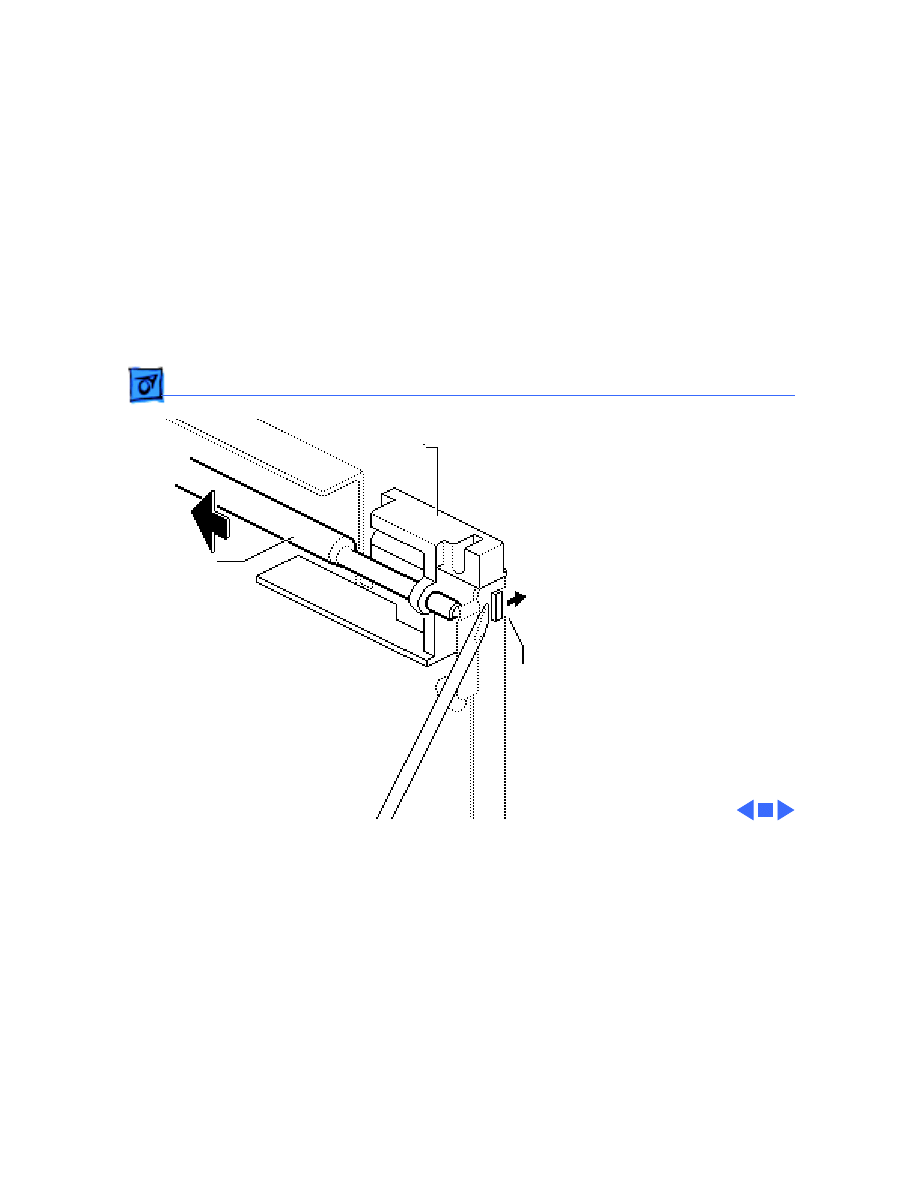
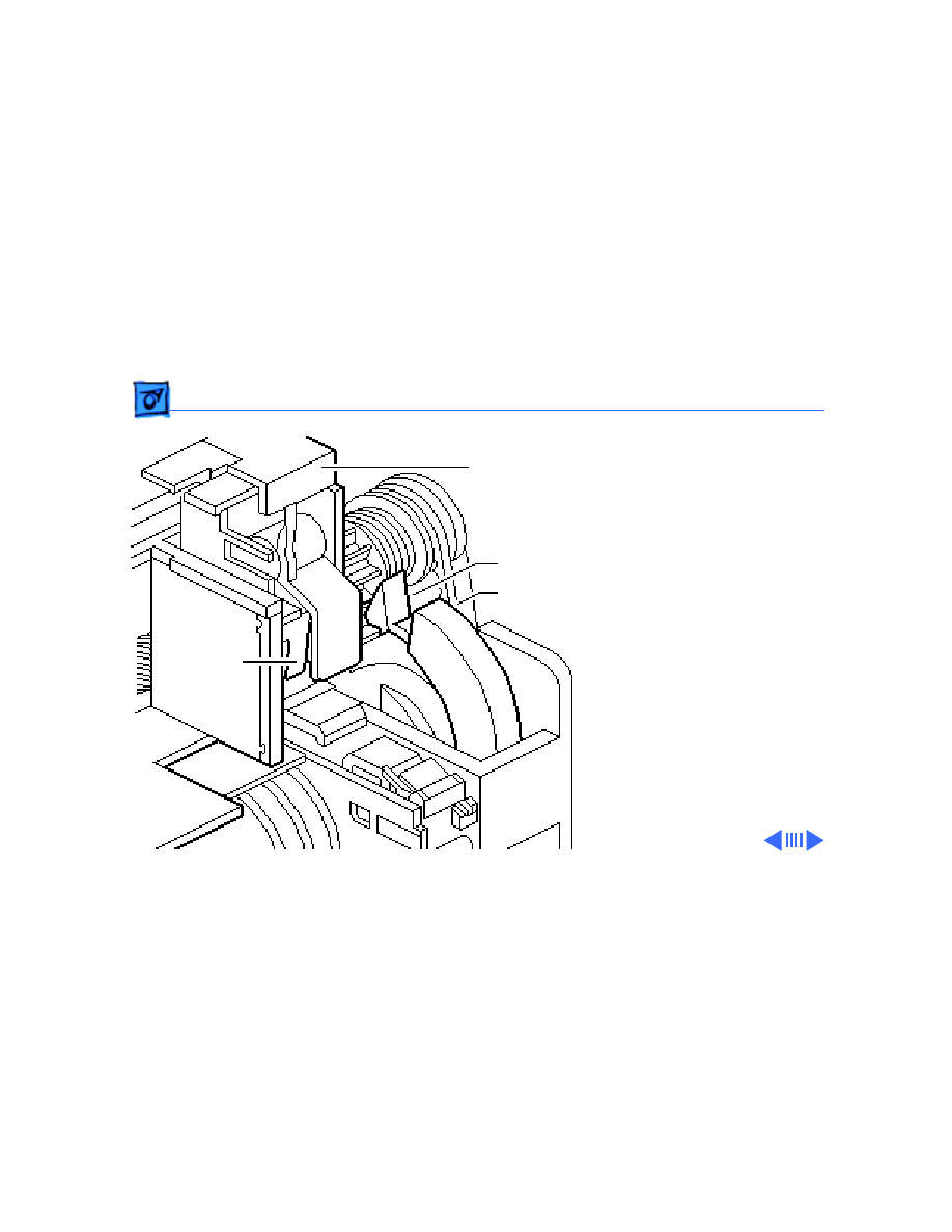
Revision Identification - 1
Revision
Identification
Note:
This procedure
explains how to
distinguish between
Revision A and Revision
B of the StyleWriter.
You must replace
Revision A and
Revision B logic boards
and printer frames
like-for-like.
1 Lower the front access
cover.
Front
Access
Cover
Additional Procedures
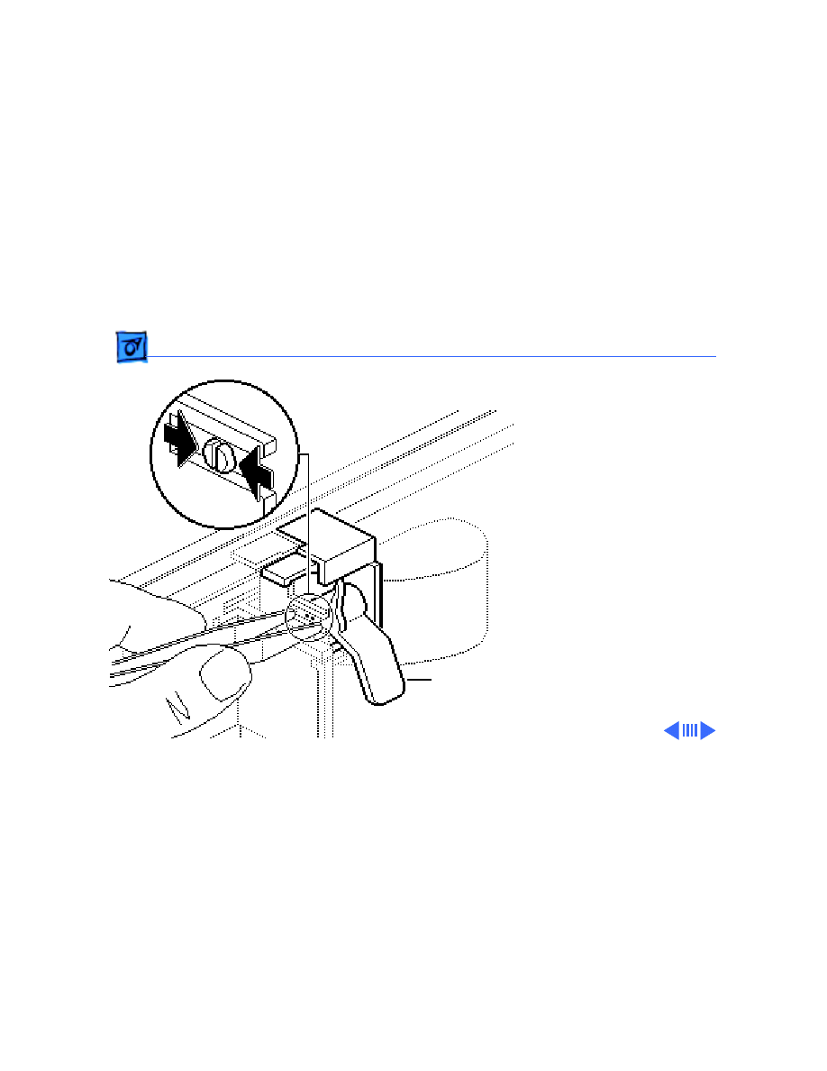
Revision Identification - 2
2 Rotate the carriage
worm screw until the V-
groove of the large gray
gear faces up.
V-Groove
Gray Gear
Worm
Screw
Additional Procedures
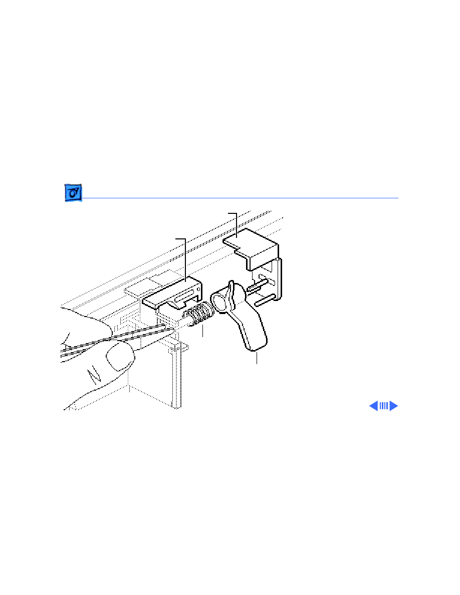
Revision Identification - 3
Note:
It may be
necessary to push gently
on the carriage hook
assembly or to rotate the
worm screw slightly to
slide the carriage hook
assembly.
3 Slide the carriage hook
assembly to the left by
guiding the lock flap
through the V-groove of
the large gray gear.
Carriage Hook
V-Groove
Large Gray
Lock Flap
Assembly
Gear
Additional Procedures
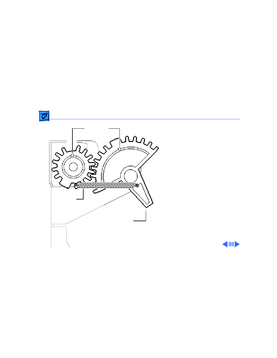
Revision Identification - 4
4 If the gear next to the
spring and at the right
end of the worm screw is
black, install the logic
board and printer frame
assembly for Revision A.
If the gear is gray,
install the logic board
and printer frame
assembly for Revision B.
Note:
Revision A logic
board has QG2-5053
silkscreened on it.
Revision B logic board
has QG2-2403
silkscreened on it.
Spring
Gear
Service Source
K
Exploded View
StyleWriter
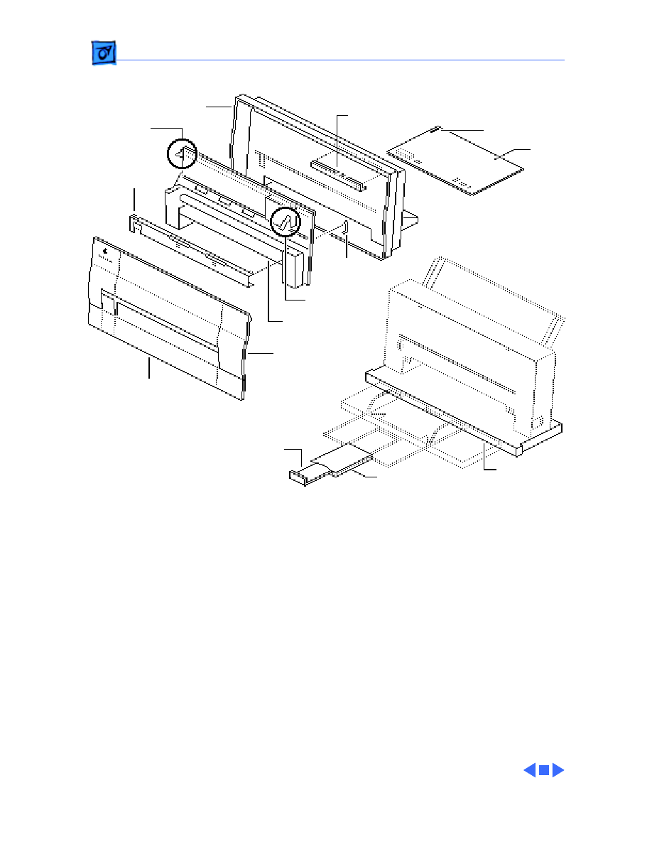
Exploded View
1
Lower Access Cover
Front Access
Cover
661-0629
Logic
661-0630
Sensor
Paper
890-0286
982-0062
941-5224
076-0400
076-0336
949-0308
949-0309
Platen Cover
076-0388
949-0311
970-0269
Rod Support
Extension Guide/
922-1695
and Base
Output Tray
076-0401
Output Tray Size Extension
Fuse
Operation Panel
Cartridge Hook
Printer Frame
Forms
Rear Cover
Board
Assembly
Assembly
Thickness
Lever
Document Outline
- StyleWriter
- Basics
- Specifications
- Troubleshooting
- Take Apart
- Additional Procedures
- Exploded View
Wyszukiwarka
Podobne podstrony:
Apple Portable StyleWriter Service Source
Apple StyleWriter II Service Source
Apple ImageWriter II Service Source
Apple ImageWriter II Service Source
Apple ImageWriter LQ Service Source
Apple LaserWriter Plus Service Source
Apple Envelope Feeder Service Source
Prezentacja firmy MARSTATE SERVICE BHP PPOZ PPT
System open source NauDoc (1)
hplj 5p 6p service manual vhnlwmi5rxab6ao6bivsrdhllvztpnnomgxi2ma vhnlwmi5rxab6ao6bivsrdhllvztpnnomg
PAT DS 350 Graphic Modular GM Service Data
Oberheim Prommer Service Manual
Funai Hita9801 Service Note
03 Service Specifications
Korg SQ 10 Service Manual
OIL SERVICE
MAC1500 service manual
więcej podobnych podstron