
APPLICATION NOTE
1/5
AN486/0692
by L. Wuidart, J.M. Ravon
ABSTRACT
Cordless and portable battery powered equipment
are proliferating thanks to the increasing capacity of
rechargeable Ni-Cd batteries. A useful feature in
applications where the battery is rapidly discharged,
such as power tools, is ultra fast charging in under
an hour. The solution described in this paper is an
efficient 100kHz converter charging a Ni-Cd battery
in half an hour. The battery charge is monitored by a
low cost microcontroller (ST6210) enabling battery
voltage identification, temperature monitoring and
charge control.
1. INTRODUCTION
Today, many types of cordless and portable
equipment are supplied by a Ni-Cd battery. Ultra
fast charging in under one hour is a very attractive
service for users. Such a short charging time requires
a charge control circuit that is more complex than for
standard chargers.
The power converter presented in this paper is able
to fully charge a common Ni-Cd battery pack of
7.2V/1.2Ah in 30 minutes. It has a corresponding
output power capability of roughly 35W and operates
as a current source providing a constant 3.5A current
to the battery while charging.
The battery charger is controlled by a low cost
microcontroller, the ST6210. This control is
compatible with the charge of Ni-Cd battery packs
from 2 to 6 cells (2.4V to 7.2V). The microcontroller
IC is supplied from an auxiliary winding of the power
transformer.
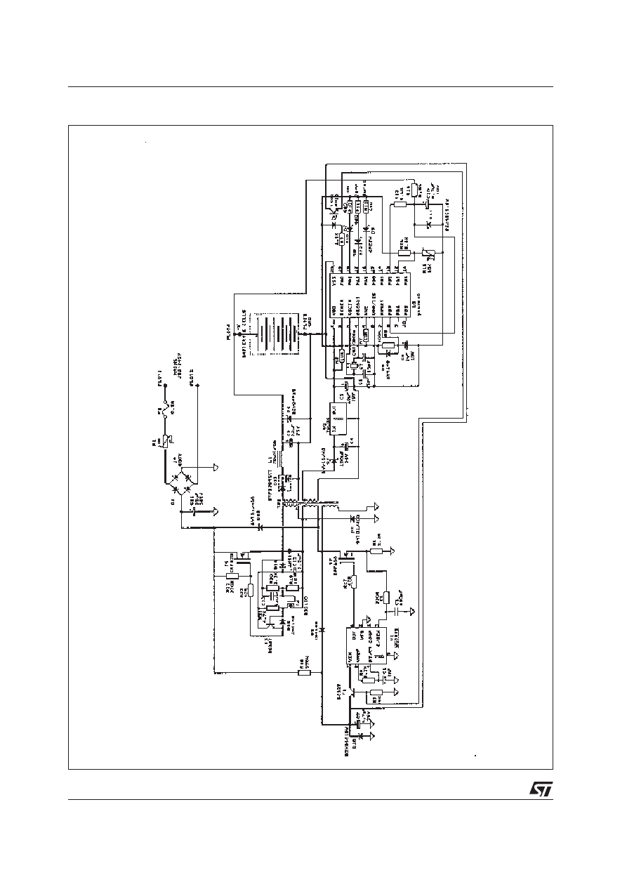
2. THE POWER CONVERTER
2.1 Circuit description
The asymmetrical half-bridge is considered today
as one of the most attractive topologies for the
primary side of a 220V ac off-line Switch Mode
Power Supply, SMPS, see figure 1.
Contrary to single switch structures, the leakage
inductance of the power transformer is much less
critical. The two demagnetisation diodes,
BYT01/400 provide a simple non-dissipative way to
systematically clamp the voltage across the switches
to the input DC voltage, V
in
. This allows the use of
standard 500V Power MOSFETs such as the isolated
lSOWATT220 packaged lRF820FI.
The power converter is totally controlled from the
primary side with a standard PWM control IC, the
UC3845, regulating in current mode. A single
optocoupler controls how the SMPS functions, either
in battery charge mode or in burst mode standby
current charge. The charger is controlled from the
secondary side of the SMPS by the microcontroller
via this optocoupler.
The switching frequency has been fixed at 100kHz,
in order to keep the magnetic part to a reasonable
manufacturing cost level. The power transformer
and the output inductor can be integrated on a single
ferrite core [1][2]. Well optimised, this integrated
magnetic technique can bring significant shrinking
of the power converter size.
2.2 “Transformerless” driver
In an asymmetrical half bridge, the high side Power
MOSFET requires a floating level shifter circuit in
order to be driven properly. Usually, this level shifter
function is realised with a pulse transformer.
In this application, the level shifter is simply an
auxiliary winding of the power transformer plus a
few discrete small signal devices (see figure 1).
The high side Power MOSFET is turned on as soon
as the transformer primary inductance is completely
demagnetised.
At turn off, the high side Power MOSFET is
synchronised with the low side device by the voltage
polarity inversion across the auxiliary winding.
2.3 Current mode forward
A Ni-Cd battery requires charging with a constant
current. A current mode control is the recommended
way to realise such a charge characteristic. In a
Forward converter, the primary peak current gives
an image of the current flowing in the output choke.
An output current ripple of 25% instead of the typical
A COST EFFECTIVE ULTRA FAST Ni-Cd BATTERY CHARGER
APPLICATION NOTE
2/5
Figure 1. Ultra fast Ni-Cd battery charger schematic
3/5
APPLICATION NOTE
voltage variations (from 245V DC to 375V DC).
A low cost PWM current mode IC such as UC3845
is well suited to regulate the complete power
converter efficiently.
3. BATTERY CHARGE CONTROL
3.1 Ultra fast charge control method
For ultra fast charge systems - under half an hour -
the majority of battery manufacturers recommend
the negative delta voltage method (-
∆
V) otherwise
called negative slope cut-off circuit [3] [4].
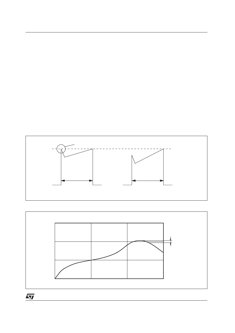
When a Ni-Cd battery reaches full charge, its voltage
decreases slightly (see figure 3).
The negative delta voltage method (-
∆
V) consists of
stopping the charge as soon as the voltage
characteristic slope becomes negative. This
10% encountered in conventional forward SMPSs,
is quite acceptable for correct charge of Ni-Cd
batteries. A larger output current ripple also gives a
steeper primary current ramp (see figure 2).
This way, the current spike due to rectifier recovery,
typically occurring on the leading edge of the
waveform, does not stop the pulse prematurely.
The current mode control can be easily realised with
a sufficient noise immunity from the primary side by
using a simple current sense resistor (see figure 1).
Constant DC output current is regulated by limiting
the primary peak current to a fixed value.
This type of current mode control provides a natural
pulse-by-pulse short-circuit protection. Moreover, this
current mode control supplies the battery with a
constant current of 3.5A whatever the input line
Ni-Cd cell voltage (V)
Charging time
1.6
1.5
1.4
1.3
-
∆
V
(-10mV/cell)
V
COMPARATOR
Premature turn-off
t
on
t
on
Current sense
voltage
Conventional forward:
10% ripple current
Battery charger:
25% ripple current
Figure 2. Using a steeper primary current ramp to cancel effect of diode recovery current spike
Figure 3. Charging characteristics of a single Ni-Cd cell
APPLICATION NOTE
4/5
technique allows the very rapid charge of a Ni-Cd
battery, near to its full capacity. Moreover, no
compensation for the age of the battery is required
because only relative voltages are measured.
In this application, the battery voltage is sensed by a
ST6210 micro-controller housed in 20 pin dual in
line package. The integrated analogue to digital
(A/D) converter of this microcontroller is able to
detect a typical voltage drop of -10mV/cell. The
overall system is reset after each new mains
connection. The ST6210 can automatically identify
the battery voltage from 2 to 6 cells (2.4V to 7.2V).
3.2 Monitoring functions
The battery charge is totally monitored by an 8-bit
HCMOS micro-controller (in PDIP or PSO 20 pin
package), the ST6210 [5]. By using this
microcontroller, additional monitoring functions can
be easily added to the ultra fast charge control
program.
3.2.1 Stand-by current charge: Burst mode
Once the negative voltage drop has been detected
by the microcontroller, the ultra fast charging is
stopped and the power converter supplies the battery
with a stand-by current of around 100mA. This
stand-by charge is provided by burst mode current
control.
The converter is successively turned on and off
at 50Hz with a small duty cycle of 0.03. The
microcontroller manages this burst mode from the
secondary side via an optocoupler, to the auxiliary
supply of the PWM control IC (UC 3845).
Thanks to the low current consumption of this
HCMOS micro-controller, a small 100
µ
F reservoir
capacitor (see figure 1) is sufficient to keep the
ST6210 properly powered during the off periods of
the burst mode.
3.2.2 Battery temperature protection
A Temperature protection is simply realised by using
an NTC resistor placed on the battery pack. This
NTC is directly connected to another input of the
A/D converter of the ST6210. When the battery
temperature reaches 40
o
C during an Ultra Fast
charge phase, the micro-controller turns the converter
into burst mode to protect the battery.
3.2.3 Battery presence
The micro-controller detects whether the battery pack
is connected or not. When the battery is not
connected, the microcontroller turns the converter
into burst mode. The resulting stand-by current
(100mA) flows into the output Transil diode
(BZW04P15, see figure 1).
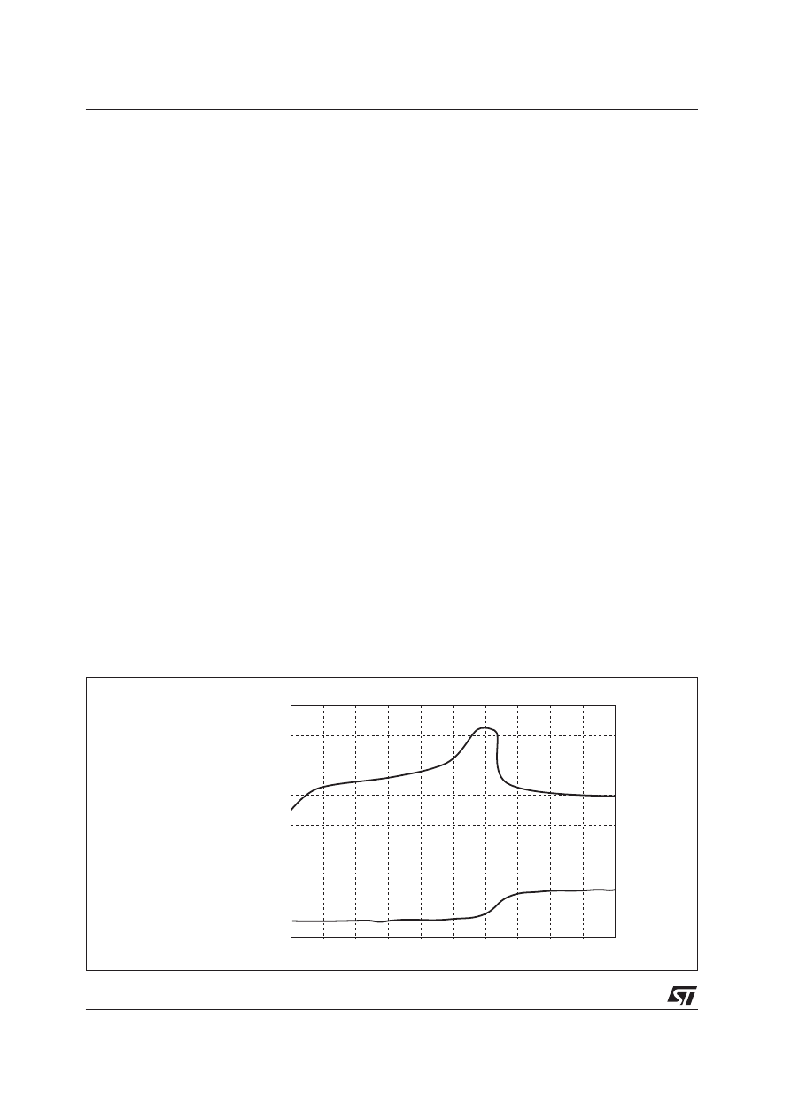
4. PRACTICAL RESULTS
The battery voltage and pack temperature versus
charging time are shown in figure 4. These recordings
have been made with a popular 1.2Ah/7.2V Ni-Cd
battery pack for cordless drills. The temperature of
the battery pack does not exceed 32
o
C for an ambient
temperature of 23.6
o
C.
Battery voltage (V)
8.2
9.0
9.8
Battery pack
temperature (
o
C)
24
32
Charging time
Figure 4. Battery voltage and pack temperature versus charging time

5/5
APPLICATION NOTE
5. CONCLUSION
Charging a Ni-Cd battery in half an hour can save
battery packs and time. It can expand the use of
battery powered equipment, especially for
professional applications. Such an ultra fast charge
has to be carefully monitored to maximise the life
time of the battery and the charge safety. Moreover,
this improvement should be achieved with compact
equipment including a minimum of components.
The forward half-bridge circuit for this battery charger
has been realised without any pulse transformer.
The paper shows that an ultra fast charge can be
totally monitored by a single 20 pin HCMOS
microcontroller, the ST6210. The actual software
includes a stand-by charge, temperature protection,
battery presence detection and battery voltage rating
identification.
Other specific requirements can be implemented
inside the existing microcontroller program.
REFERENCES
[1] Core selection for Integrated-magnetic power
converters.
G.E. Bloom, Powertechnics Magazine - June
1990.
[2] Ultra fast Ni-Cd battery charger with integrated
magnetic.
L. Wuidart, PClM - June 1991 - Nürnberg
[3] Fast-charge batteries
A. Watson-Swager, EDN, Dec. 7,1989.
[4] Focus on rechargeable batteries: economic
portable power.
M. Grossman, Electronic Design, March 3 1988.
[5] Ultra fast Ni-Cd battery charging using ST6210
micro-controller.
L. Wuidart, P. Richter, ST6 APPLICATION
MANUAL, AN433.
Information furnished is believed to be accurate and reliable. However, STMicroelectronics assumes no responsibility for the consequences
of use of such information nor for any infringement of patents or other rights of third parties which may result from its use. No license is
granted by implication or otherwise under any patent or patent rights of STMicroelectronics. Specification mentioned in this publication are
subject to change without notice. This publication supersedes and replaces all information previously supplied. STMicroelectronics products
are not authorized for use as critical components in life support devices or systems without express written approval of STMicroelectronics.
The ST logo is a trademark of STMicroelectronics
1999 STMicroelectronics - Printed in Italy - All Rights Reserved
STMicroelectronics GROUP OF COMPANIES
Australia - Brazil - China - Finland - France - Germany - Hong Kong - India - Italy - Japan - Malaysia - Malta - Morocco -
Singapore - Spain - Sweden - Switzerland - United Kingdom - U.S.A.
http://www.st.com
Wyszukiwarka
Podobne podstrony:
NI MH CHARGER NC E2 & NP E2
akumulatory ni mh tabela
NI[2]
Bożenna Odowska, psychologia osób z ni
WARIANT C, FIR UE Katowice, SEMESTR IV, Ubezpieczenia, chomik, Ubezpieczenia (kate evening), Ubezpie
ankieta mh
NI Spis tresci id 318044 Nieznany
9 CD 4212 2 battery charger
IZOPLAST MH
01 02 Taikyoku Sono Ichi, Ni
NI 1 1 03 2009 r
Materiał wyrazowo obrazkowy lt d m mi n ni
NI MI SI RODZINNY DOM, TEKSTY
Uczenie się dzieci ni
test mh
Charge asc
TECAMIDf MH cz
Erich Von?niken Kosmiczne miasta w epoce kamiennej
GWSH - tur pielgrzymkowa, religie świata, Judaizm (Mozaizm) - religia wyznawana przez Żydów mająca n
więcej podobnych podstron