
Repair Guide to Halley
(On-Site Training)
ASUSTeK
ASUSTeK
Mingwei
Mingwei
Kang
Kang
• ID Concept
• Hardware Features
• System Architecture
• Peripheral Trouble Shooting
• Power-On Sequence
• Appendix
• Q & A
Agenda
Agenda
Agenda

ID Concept
ASUSTeK Proprietary and Confidential
ASUSTeK Proprietary and Confidential
4
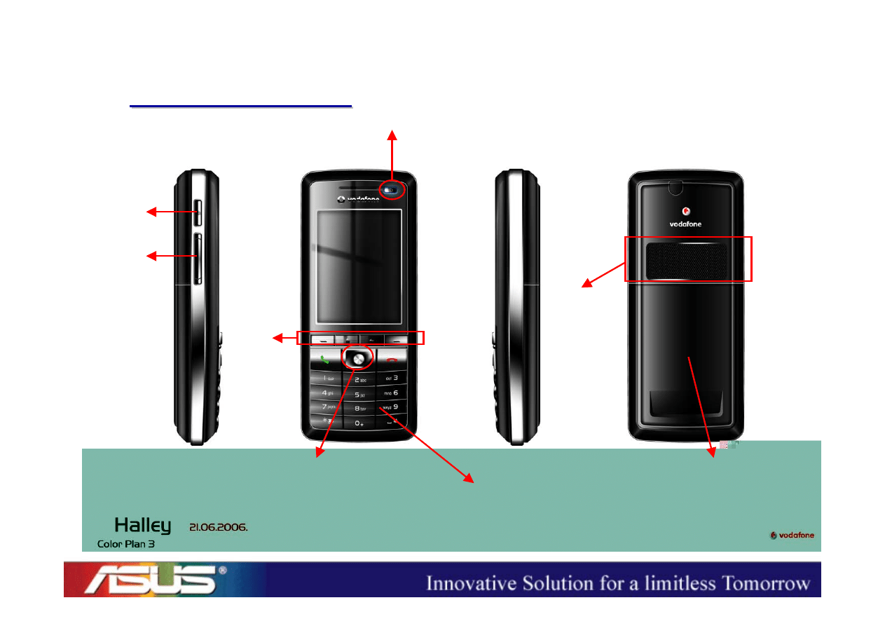
ID Concept
ID Concept
ID Concept
Power Key
Volume
Up/Down
Browser
5-way Navigator
Hard
/Soft
Keys
Dial/End & Numeral Keys
Speaker
Battery Cover

Hardware Features

ASUSTeK Proprietary and Confidential
ASUSTeK Proprietary and Confidential
6
Halley Hardware Features
Halley Hardware Features
• Dual Chip Solution
– Application CPU : PXA270 312MHz
– Communication CPU : PXA90x 312MHz
• Memory
– 128MB NAND Flash
– 64MB SDRAM
• 2.2” QVGA (240 x 320) TFT LCD (65K colors)
• Key : Hard Keys, Soft Keys, and 5-way Navigator
• Micro-SD Memory Card Slot (up to 1GB)
• Lithium-ion Battery (1100mAh)

System Architecture
ASUSTeK Proprietary and Confidential
ASUSTeK Proprietary and Confidential
8
Halley System Architecture
Halley System Architecture
2.2" TFT
LCD
Microphone
Receiver
Headset
Jack
PXA270
312MHz
Mini-AB USB
connector
Micro-SD
card slot
AFE/
Codec
WCDMA RF
GSM RF
PXA90x
312MHz
SIM
connector
PSRAM
PMIC
Loud speaker
Vibrator
LEDs
App. CPU
PA
PA
Saw
Dup
SDRAM
NAND
Bluetooth
Keypad
Comm. CPU
Battery
Charger

Peripheral Trouble
Shooting
ASUSTeK Proprietary and Confidential
ASUSTeK Proprietary and Confidential
10
Peripheral Trouble Shooting
• MMI Test Program
• LCD
• Keypad / Side keys
• Receiver
• Speaker / MIC
• SIM / Micro-SD
• Headset
• Charging / Sync
ASUSTeK Proprietary and Confidential
ASUSTeK Proprietary and Confidential
11
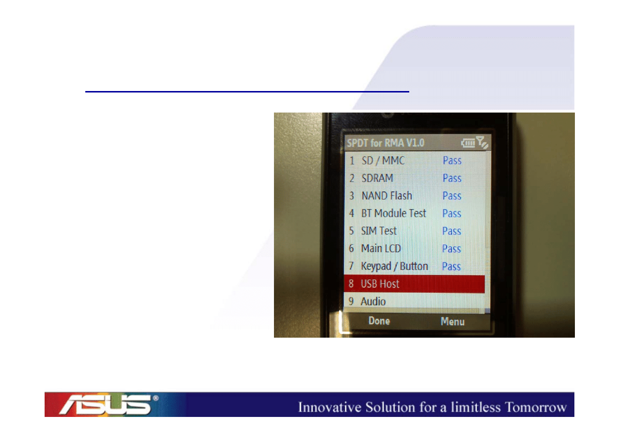
MMI Test Program (1/2)
1. SD/MMC
2. SDRAM
3. NAND Flash
4. BT Module Test
5. SIM
6. Main LCD
7. Keypad/Button
8. USB Host
ASUSTeK Proprietary and Confidential
ASUSTeK Proprietary and Confidential
12
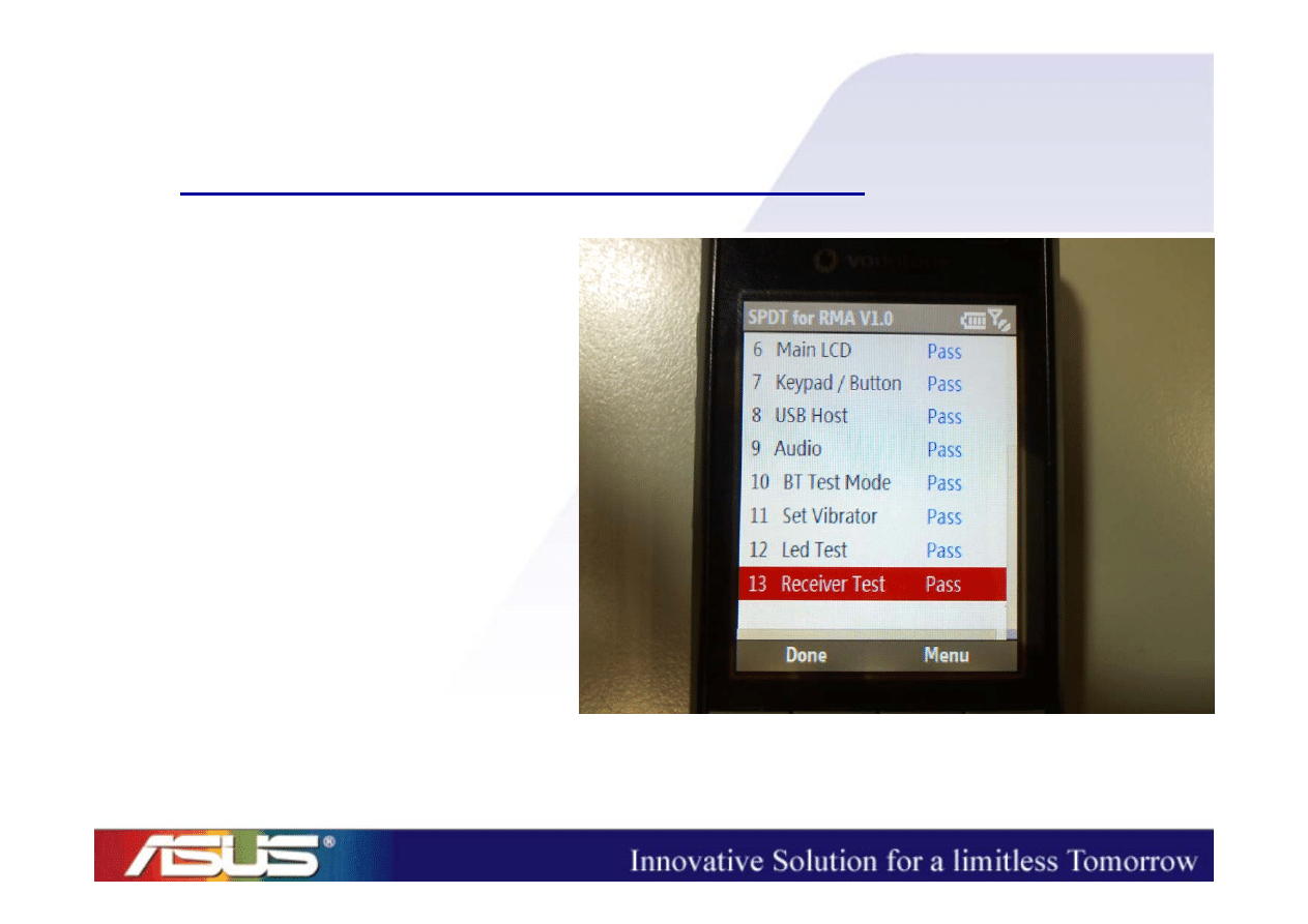
MMI Test Program (2/2)
9. Audio
10. BT Test Mode
11. Set Vibrator
12. LED Test
13. Receiver
ASUSTeK Proprietary and Confidential
ASUSTeK Proprietary and Confidential
13
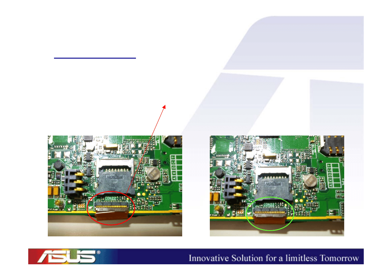
LCD (1/2)
• White Screen => take the device apart
– LCD FPC (
oblique
?)
– LCD CON (mounted properly?)

ASUSTeK Proprietary and Confidential
ASUSTeK Proprietary and Confidential
14
LCD (2/2)
• Black Screen => take the device apart
– LCD FPC (
damaged
?)
– LCD CON (mounted properly?)
ASUSTeK Proprietary and Confidential
ASUSTeK Proprietary and Confidential
15
Keypad
• Keypad no function=> take the device apart
– Main Board CON
– Serial Resistors (mounted properly?)
– Keypad CON
– Keypad FPC
ASUSTeK Proprietary and Confidential
ASUSTeK Proprietary and Confidential
16
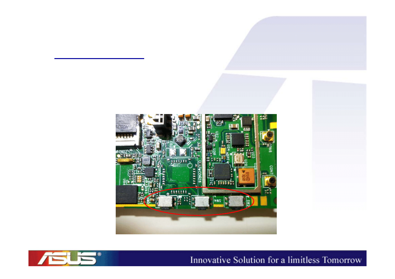
Side Keys
• No function => take the device apart
– Side Keys fall off ?? (check its pins)
ASUSTeK Proprietary and Confidential
ASUSTeK Proprietary and Confidential
17
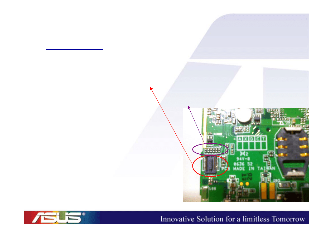
Receiver
• No Sounds Output => take the device apart
– Check the contact between the receiver pins and
the pads on the main PCB
(Is the pin oblique/sunk?)
– Single part problem? (change another one)

ASUSTeK Proprietary and Confidential
ASUSTeK Proprietary and Confidential
18
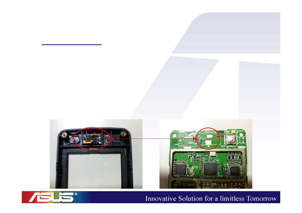
Speaker (1/2)
• No Sounds Output
=>
Press the neighbors of the Speaker
– If there is a sound output when we press it but
there is no sound output as long as we release
our hands on the speaker, we need to take the
device apart and then reassemble it.
ASUSTeK Proprietary and Confidential
ASUSTeK Proprietary and Confidential
19
Speaker (2/2)
• No Sounds Output when we have already
pressed the neighbors of the Speaker
=> take the device apart
– Check the contact between the speaker pins and
the stand-off on the main PCB
(Is the pin/stand-off oblique?)
– Single part problem?
(change another one)
ASUSTeK Proprietary and Confidential
ASUSTeK Proprietary and Confidential
20
MIC
• Cannot record => take the device apart
– Is the rubber set properly?

ASUSTeK Proprietary and Confidential
ASUSTeK Proprietary and Confidential
21
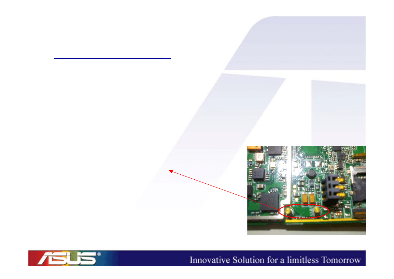
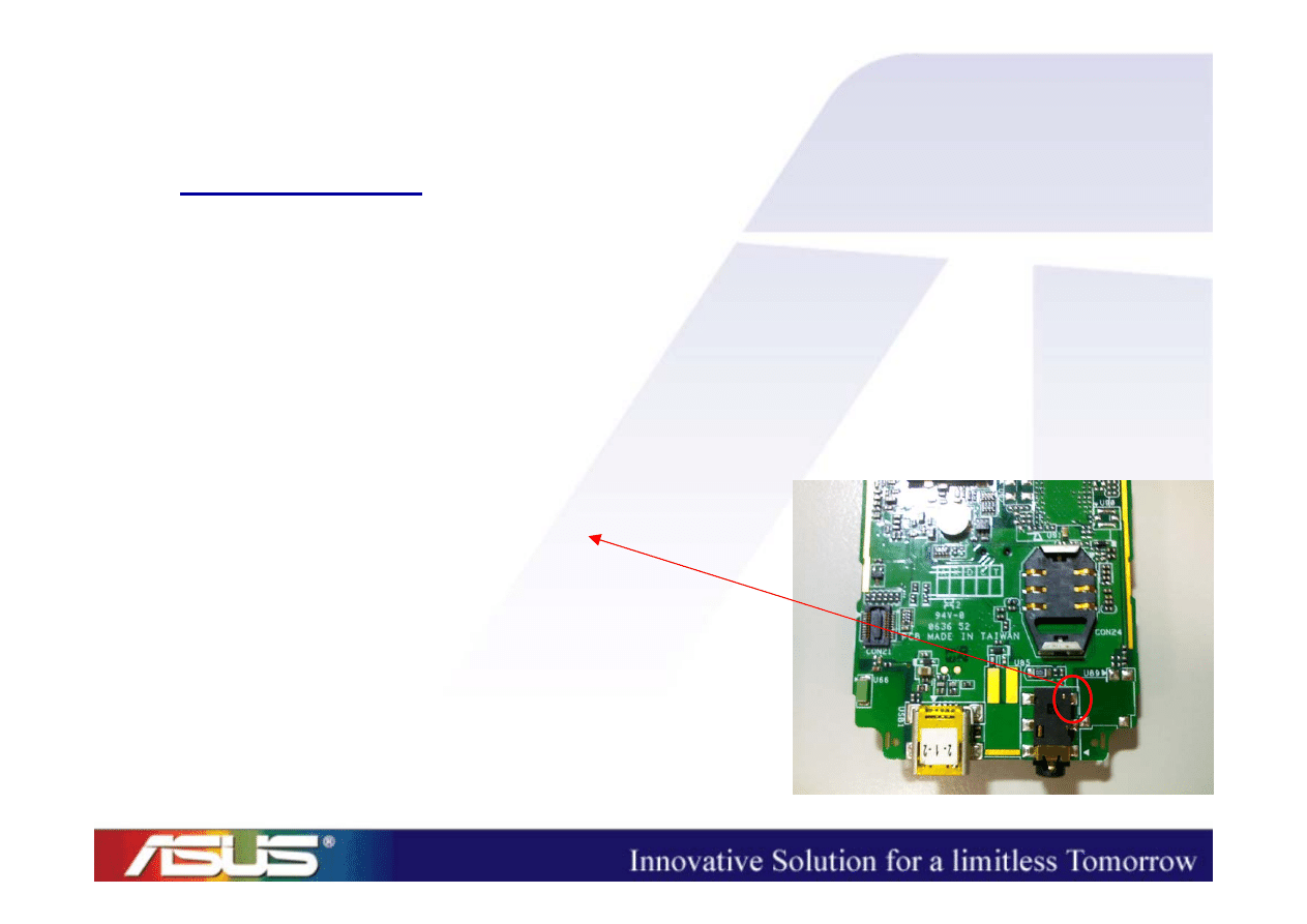
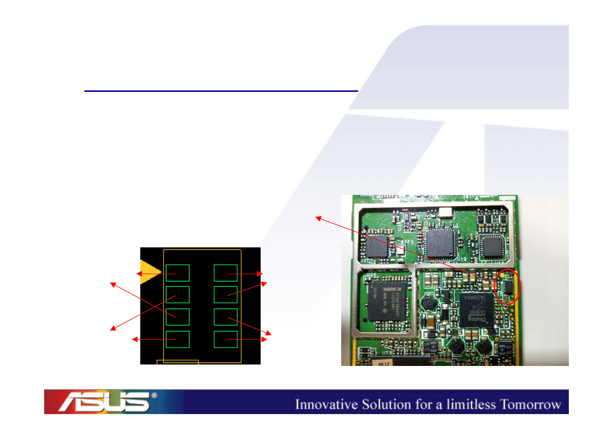
SIM
• SIM card cannot be accessed
=> take the device apart
– Check the contact between the SIM CON and
the pads on the main PCB
ASUSTeK Proprietary and Confidential
ASUSTeK Proprietary and Confidential
22
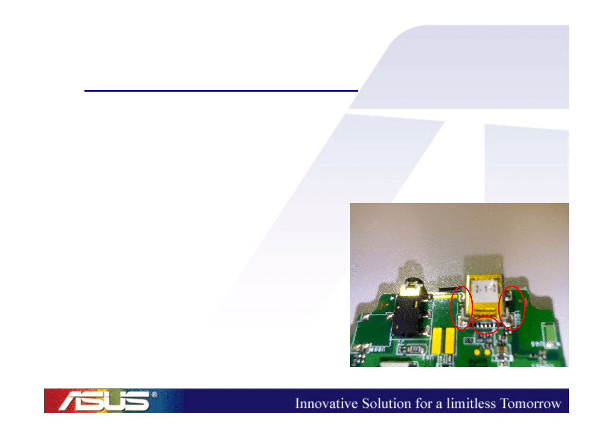
Micro-SD
• Micro-SD card cannot be accessed
=> take the device apart
– Check the contact between the Micro-SD CON
and the pads on the main PCB
– Are the pins of Micro-SD CON oblique/sunk?
(P.S. The pins mentioned above are the ones which are in touch with
external Micro-SD card.)
ASUSTeK Proprietary and Confidential
ASUSTeK Proprietary and Confidential
23
Headset
• Cannot be recognized when the headset is
plugged into the audio jack
=> take the device apart
– Check the status of the headset detect pin
– Headset Mode : 1
– Normal Mode : 0
ASUSTeK Proprietary and Confidential
ASUSTeK Proprietary and Confidential
24
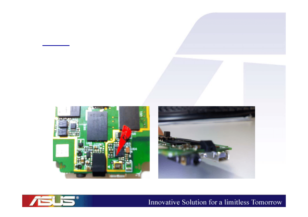
Charging/Sync (1/2)
• Charging LED => Red light
• USB/Charger cannot recognized when they
were plugged into the USB CON
– Check the contact between
USB CON pins and the
pads on the main PCB
ASUSTeK Proprietary and Confidential
ASUSTeK Proprietary and Confidential
25
Charging/Sync (2/2)
• Charging LED => Red light
• Cannot be charged when the charger is
connected to the device
– Check the PMOS (Q5)
CH_Source
CH_Gate
VCHG_VBUS
CH_OUT

Power-On Sequence

ASUSTeK Proprietary and Confidential
ASUSTeK Proprietary and Confidential
27
Halley System Architecture
Halley System Architecture
2.2" TFT
LCD
Microphone
Receiver
Headset
Jack
PXA270
312MHz
Mini-AB USB
connector
Micro-SD
card slot
AFE/
Codec
WCDMA RF
GSM RF
PXA90x
312MHz
SIM
connector
PSRAM
PMIC
Loud speaker
Vibrator
LEDs
App. CPU
PA
PA
Saw
Dup
SDRAM
NAND
Bluetooth
Keypad
Comm. CPU
Battery
Charger

ASUSTeK Proprietary and Confidential
ASUSTeK Proprietary and Confidential
28
Power
Power
-
-
On Sequence
On Sequence
• When the device cannot boot up, we need to
check the power-on sequences.
– App. CPU (PXA270) power-on sequence
– Comm. CPU (PXA90x) power-on sequence
ASUSTeK Proprietary and Confidential
ASUSTeK Proprietary and Confidential
29
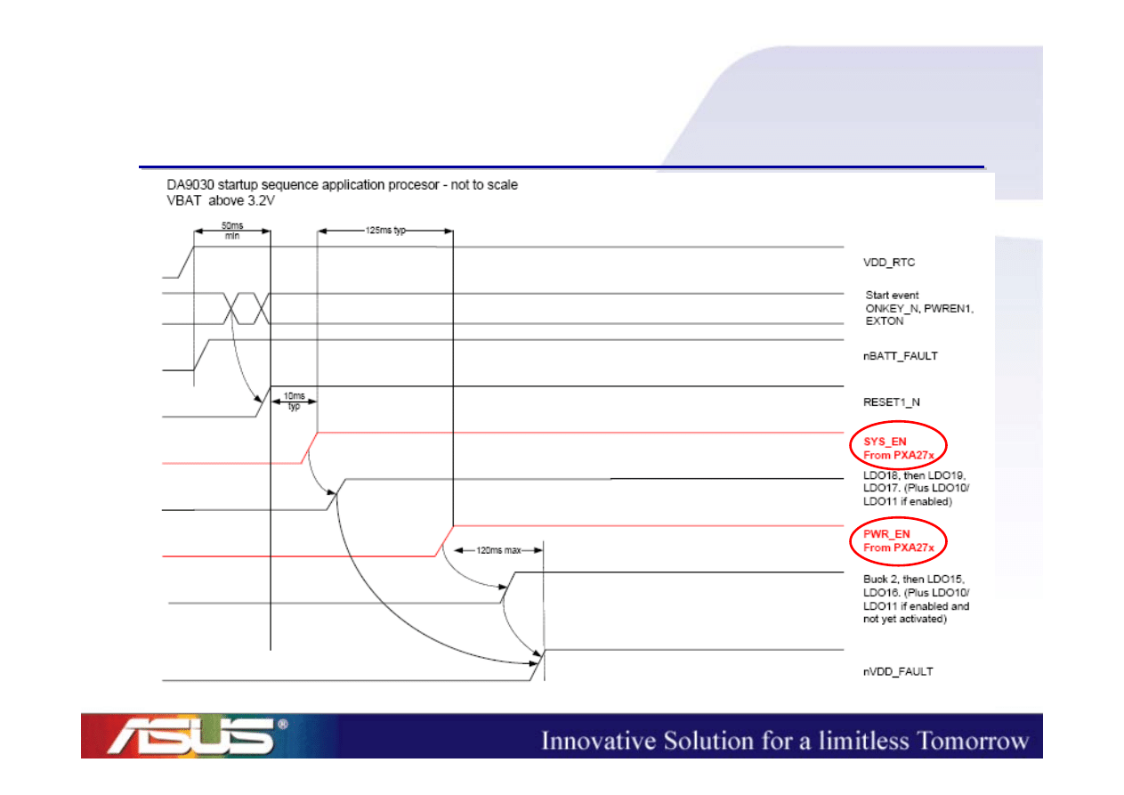
App. CPU Power
App. CPU Power
-
-
On Sequence(1)
On Sequence(1)
ASUSTeK Proprietary and Confidential
ASUSTeK Proprietary and Confidential
30
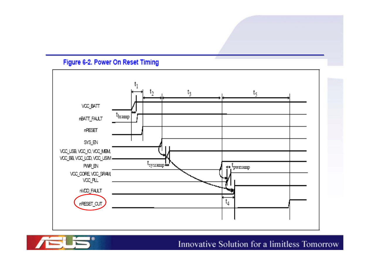
App. CPU Power
App. CPU Power
-
-
On Sequence(2)
On Sequence(2)
ASUSTeK Proprietary and Confidential
ASUSTeK Proprietary and Confidential
31
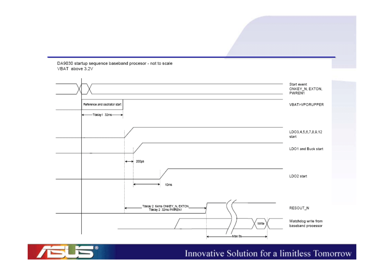
Comm. CPU Power
Comm. CPU Power
-
-
On Sequence
On Sequence
ASUSTeK Proprietary and Confidential
ASUSTeK Proprietary and Confidential
32

ASUSTeK Proprietary and Confidential
ASUSTeK Proprietary and Confidential
33
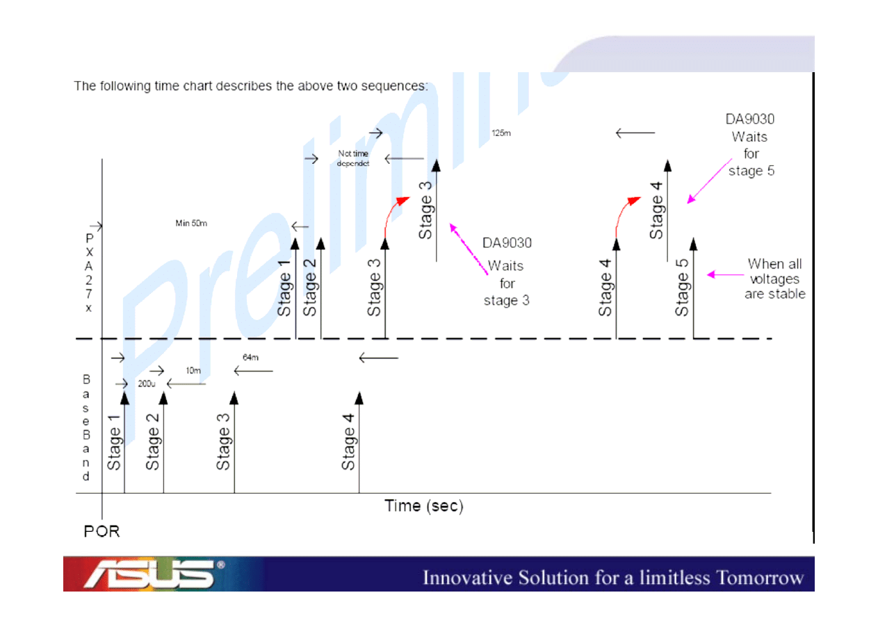
Power
Power
-
-
On Sequence Check
On Sequence Check
a)
VLDO_RTC (TP37)
b)
32kHz
c)
BUCK_VCORE_1 (L47.2)
d)
VLDO2_1V8
e)
13MHz
f)
SYS_EN (Q3.5)
g)
PWR_EN (TP1)
h)
BUCK_VCORE_2 (L48.2)
i)
nRESET_OUT (TP7)
j)
nNF_CS (TP6)

Appendix

ASUSTeK Proprietary and Confidential
ASUSTeK Proprietary and Confidential
35
Schematics Overview (1/2)
Schematics Overview (1/2)
1.
Block Diagram
2.
Revision History (Ignore this page)
3.
GPIO Table
4.
App. CPU (1/3)
5.
App. CPU (2/3)
6.
App. CPU (3/3)
7.
SDRAM/Flash
8.
Bluetooth
9.
Micro-SD/USB
10. LCD/LED/Vibrator

ASUSTeK Proprietary and Confidential
ASUSTeK Proprietary and Confidential
36
Schematics Overview (2/2)
Schematics Overview (2/2)
11. Audio
12. Comm. CPU
13. Codec/AFE
14. Ignore this page
15. Function Key/Keypad
16. Ignore this page
17. PMIC
18. BB/RF Interface
19. GSM/GPRS
20. WCDMA
21. Debug

Q & A
Q & A
(
(
mingwei
mingwei
_kang@asus
_kang@asus
.com
.com
.tw
.tw
)
)

Thank you !
Thank you !
Document Outline
- Repair Guide to Halley (On-Site Training)
- ID Concept
- ID Concept
- Hardware Features
- Halley Hardware Features
- System Architecture
- Halley System Architecture
- Peripheral Trouble Shooting
- Peripheral Trouble Shooting
- MMI Test Program (1/2)
- MMI Test Program (2/2)
- LCD (1/2)
- LCD (2/2)
- Keypad
- Side Keys
- Receiver
- Speaker (1/2)
- Speaker (2/2)
- MIC
- SIM
- Micro-SD
- Headset
- Charging/Sync (1/2)
- Charging/Sync (2/2)
- Power-On Sequence
- Halley System Architecture
- Power-On Sequence
- App. CPU Power-On Sequence(1)
- App. CPU Power-On Sequence(2)
- Comm. CPU Power-On Sequence
- Power-On Sequence Check
- Appendix
- Schematics Overview (1/2)
- Schematics Overview (2/2)
- Q & A
- Thank you !
Wyszukiwarka
Podobne podstrony:
Halley repair guide RF ACCO
CLP310 CLP315 CLX317x Fuser Component Repair Guide
ASUS K54LY (K54HR) Repair Guide
Credit Repair Guide
Asus E502NA Repair Guide
Halley RF Troubleshooting and Maintenance Guide V1 0
ECC G003 Guide to Repair Flow
Popular Mechanics Repairing Power Antennas
guide camino aragones pl
Herbs for Sports Performance, Energy and Recovery Guide to Optimal Sports Nutrition
Meezan Banks Guide to Islamic Banking
NLP for Beginners An Idiot Proof Guide to Neuro Linguistic Programming
freespan spec guide
Eaton VP 33 76 Ball Guide Unit Drawing
Herbs to Relieve Headaches Keats Good Herb Guide
50 Common Birds An Illistrated Guide to 50 of the Most Common North American Birds
Configuration Guide WAN Access(V100R006C00 02)
installation guide
iR Shell 3 9 User Guide
więcej podobnych podstron