D1LC compact Air Heater
Installation
Troubleshooting &
Parts Manual
Espar
April 1998
D1LC compact
For Heater Models
Release period
25 1976 05 - 12Volt
October/97-present
25 1977 05 - 24Volt
Feburary/98-present
25 1965 05 - 12Volt
April/97-October/97
25 1966 05 - 24Volt
August/96-Feburary/98
25 1895 05 - 12Volt
August/96-April/97
25 1896 05 - 24Volt
August/96-Limited

Table of Contents
Page
Introduction
Heater Warnings
........................................................
2
Introduction
........................................................
3
Specifications
........................................................
4
Principal Dimensions
........................................................
5
Mounting Pattern
........................................................
5
Heater Components
........................................................
6
Installation Procedures
Heater Location
........................................................
7
Heater Mounting
........................................................
7
Heater Air Ducting
........................................................
7
Heater Plumbing
........................................................
7
Ducting Components
........................................................
8
Fuel System
........................................................
8
Electrical Connections
........................................................
11
Exhaust/Intake Connections
........................................................
12
Operating Switches
........................................................
12
Heater Operation
Switch on
........................................................
13
Start-Up
........................................................
13
Temperature setting
........................................................
13
Temperature Control
........................................................
13
Switching Off
........................................................
13
Controls & Safety Equipment
........................................................
13
Operational Flow Chart
........................................................
14
Schematic 25 1976/1977
........................................................
15
Schematic 25 1965/1966
........................................................
16
Schematic 25 1895/1896
........................................................
17
Maintenance,
Periodic Maintenance
........................................................
18
Troubleshooting &
Basic Troubleshooting
........................................................
18
Repairs
Self Diagnostic Troubleshooting .......................................................
19
Fuel Quantity Test
........................................................
22
Component Spec chart
........................................................
22
Repair Steps
........................................................
23
Heater Parts
D1LC Compact-Parts Diagram
........................................................
26
D1LC Compact-Parts List
........................................................
29
Special Notes
Note: Highlight areas requiring special attention or clarification.
Caution: Indicates that personal injury or damage to equipment may occur unless specific guidelines are followed.
Warning: Indicates that serious or fatal injury may result if specific guidelines are not followed.

2
Heater Warnings
Warning To Installer:
Correct installation of this heater is necessary to ensure
safe and proper operation.
Read and understand this manual before attempting to
install a heater.
Warning - Explosion Hazard
1.
Heater must be turned off while re-fueling.
2.
Do not install heater in enclosed areas where
combustible fumes may be present.
3.
Do not install heaters in engine compartments of
gasoline powered boats.
Warning - Fire Hazard
1.
Install heater so it will maintain a minimum distance of
2” from any flammable or heat sensitive material.
2.
Install the exhaust system so it will maintain a
minimum distance of 2” from any flammable or heat
sensitive material.
3.
Ensure that the fuel system is intact and there are no
leaks.
Failure to follow these instructions could cause fire result-
ing in serious or fatal injur y.
Warning - Asphyxiation Hazard
1.
Route the heater exhaust so that exhaust fumes can
not enter any passenger compartments.
2.
Ensure an air tight seal will be maintained between
the heater and mounting surface and at any exhaust
connection points.
3.
Ensure that heating air supply is taken from an area
where poisonous gases will not be present.
4.
If running exhaust components through an enclosed
compartment, ensure that it is vented to the outside.
Failure to follow these instructions could cause oxygen
depletion resulting in serious or fatal injury.
Direct questions to Espar Heater Systems
USA
1-800-387-4800
CDA
1-800-668-5676
3
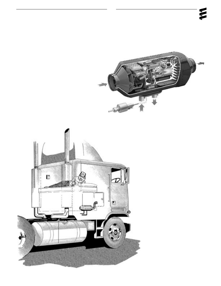
Introduction
Espar D1LC Compact Air Heater
The Espar D1LC compact is a diesel-fired 7,500 BTU/HR
air heater, quality engineered to provide a dependable
means of space heating.This heater is uniquely designed
for inside mounting and ease of installation.
The heater provides hot air to the interior of vehicles for
passenger comfort. Since the heater runs on diesel fuel
and 12 or 24 volt po wer, it is able to provide space heat
completely independently of the vehicle engine.
The heater is operated by a rheostat switch or
room thermostat. It cycles through four tempera-
ture settings (boost-high-medium-low) in order to
maintain the desired temperature.
If, in special cases, less heating capacity is required than
the heater supplies in the “Low” setting, the heater switch-
es to the “Off ” setting. Temperature and overheat limit
switches, and a specially designed heat exchanger are
among the safety features which make this heater a safe
and dependable unit.

4
Specifications
Heat Output (±10%)
7,500 BTU/hr Boost
6,150 BTU/hr High
4,100 BTU/hr Medium
2,900 BTU/hr Low
Current at 12v (±10%)
20.8 amps/hr - Star t
2.5 amps/hr - Boost
1.8 amps/hr - High
0.8 amps/hr - Medium
0.8 amps/hr - Low
Current at 24v (±10%)
11.25 amps/hr - Star t
1.25 amps/hr - Boost
0.9 amps/hr - High
0.4 amps/hr - Medium
0.4 amps/hr - Low
Fuel Consumption (±10%)
U.S.
Litre/hr
Gal/hr
Boost
.07
.27
High
.06
.21
Medium
.04
.14
Low
.03
.10
Air Flow (±10%)
50 cfm Boost
43 cfm High
30 cfm Medium
30 cfm Low
Operating Voltage Range
10.5 to 15.9 vdc at 12 vdc
21.0 to 31.8 vdc at 24 vdc
Overheat Temperature
240°F (116°C)
Shutdown (±10%)
Ambient Operating
-40°F to 122°F (-40°C to 50°C)
Temperature
Weight
7.7 lbs. (3.5kg)
Note: The heater control unit is equipped with a low
voltage cutout to prevent vehicle battery drain and
a high voltage cutout to protect heater electrical
parts.

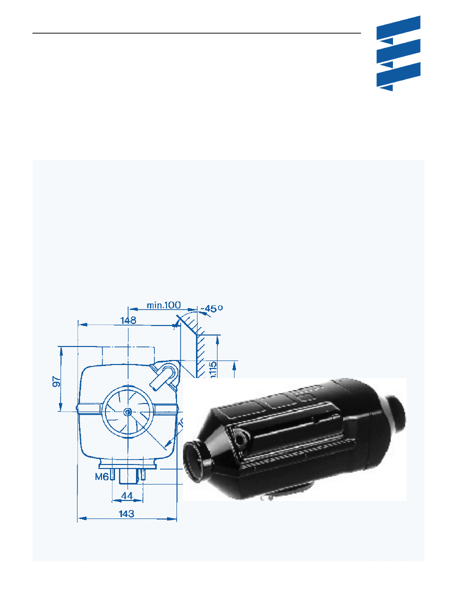
5
Mounting Pattern
If fastening to the vehicle wall/floor, make penetrations in
accordance with the hole pattern shown below. A pre-
punched mounting kit is also available as shown beside.
Principal Dimensions
* All measurements in inches
1”= 2.5 cm
6
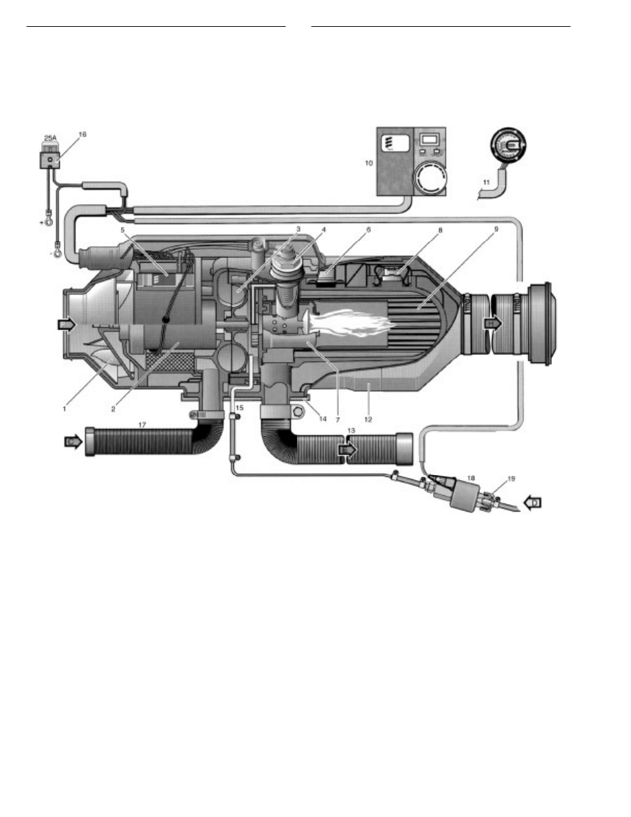
1 Hot Air Blower Wheel
2 Blower Motor
3 Combustion Air Blower Wheel
4 Glow Plug
5 Control Unit
6 Safety Thermal Sensor
7 Combustion Chamber
8 Flame Monitor
9 Heat Exchanger
10 Operating Unit (Thermostat)
11 Operating Unit (Rheostat)
12 Outer Casing
13 Exhaust Line
14 Flange Seal
15 Fuel Line
16 Main Fuse, 25 A
17 Combustion Air Intake Line
18 Fuel Metering Pump
19 Fuel Strainer
C = Combustion Air
D = Fuel
E = Exhaust
F = Fresh Air
H = Hot Air
Heater Components
7
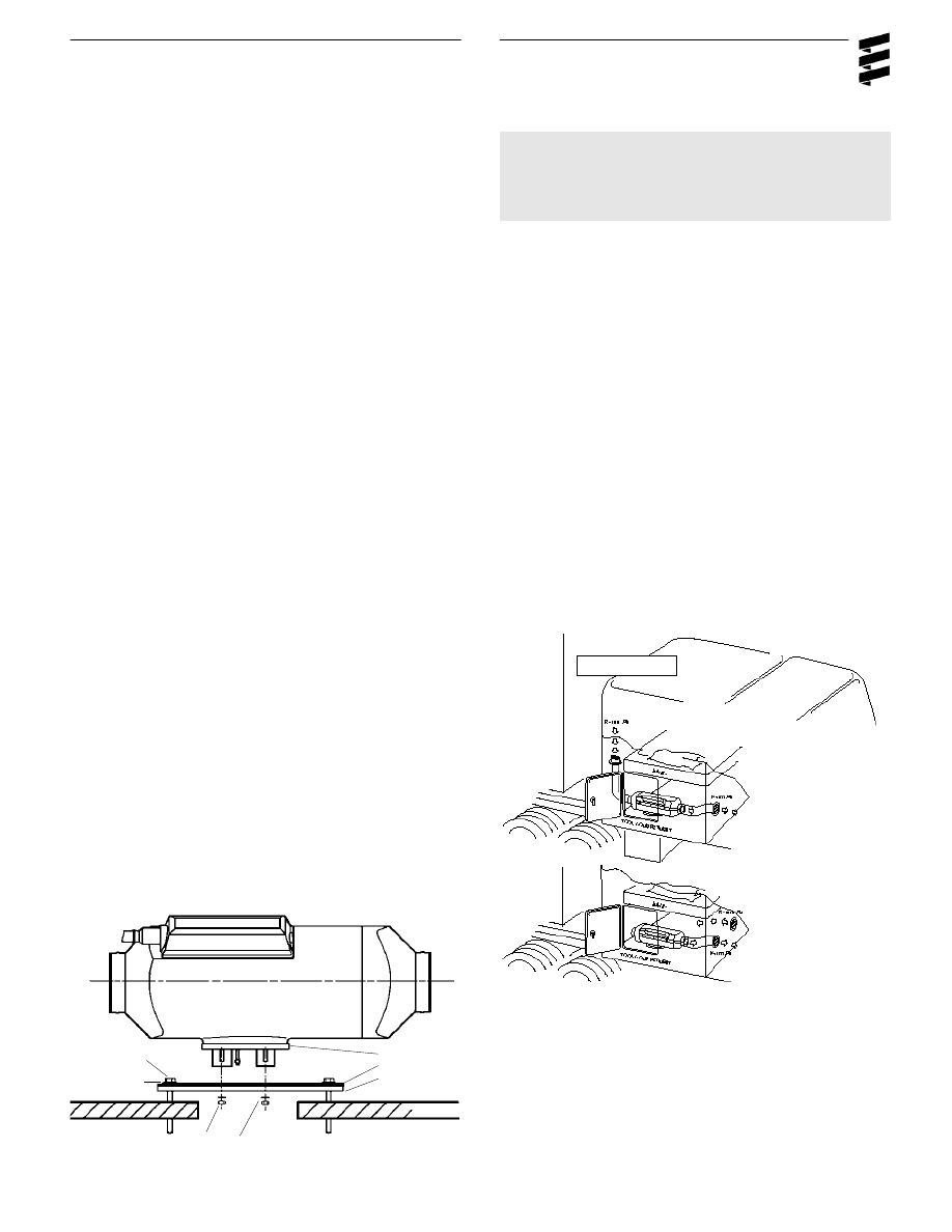
Heater Mounting Plate Installation
Figure IIA
HEX HEAD
TEK SCREW
FLAT WASHER
NUT
SPRING WASHER
SILICONE GASKET
S.S. PLATE
PLATE SEAL
Installation Procedures
Heater Location
Depending on the type of vehicle, the best location for
mounting the heater will var y. Typically, heaters are mount-
ed inside tool or luggage compartments. However, the
heater may be mounted anywhere inside the vehicle pro-
vided you adhere to the following conditions:
• Combustion air intake, exhaust and fuel inlet must be
located outside of the vehicle.
• Heater must be mounted on flat horizontal surface
providing an air tight seal between heater and vehicle.
• Do not mount the heater outside the vehicle, unless care
is taken to protect the heater from the weather.
When selecting the location, consider the following:
• Combustion air and exhaust connections.
• Ducting.
• Fuel line connections.
• Electrical connections.
Heater Mounting
A mounting plate and hardware are provided with the truck
heater kit.
• Choose heater location.
• Using template provided, drill and cut center hole. Cut
one (1) four and one half inch (4 1/2”) diameter hole or
one rectangular hole four (4”) by five (5”) inches.
• Mount heater on mounting plate with nuts and spring
washers provided.
• For ease of installation make the exhaust, combustion
air intake and fuel connections at base of heater before
mounting the heater into the vehicle .
• Position heater in vehicle and secure with “Tek” screws
provided.
Note: Tighten screws sufficiently to ensure positive seal
between mounting plate and mounting surface.
Do not over tighten.
Heater Air Ducting
Installation
A 60mm flexible duct 40 inches long, hot air outlet and
clamps are provided with the heater kit.
• In routing and installing the ducting the following criteria
must be observed:
• Run ducting with smooth bends . Avoid crushing duct.
• Position hot air outlet so that it cannot be obstructed.
• Use protective air intake grille on air inlet side of heater
to prevent objects from being sucked in.
• Ensure provisions are made for proper air return
ventilation.
• Use return air ducting for best heating efficiency
(see below).
CAB FLOOR
Return Ducting
8
Warning: Do not use existing vehicle ducting or out-
lets. Ducts and outlets must be capable of
withstanding a minimum of 300°F operat-
ing temperatures. To avoid exhaust leak-
age, the heater must always be operated
with an end cap installed.
Caution:
Do not over tighten duct clamps.
Do not position outlet so that it will blow hot
air directly at operator or at room thermostat.
Ducting Components
1. Protective Grill
3. Hose Clamp 2-2 3/4”
5. Air Outlet - Rotatable
7. 90° Bend Ducting 2 3/8”
2. Air Outlet Hood
4. Flex Duct 2 3/8”
6. Connection Piece
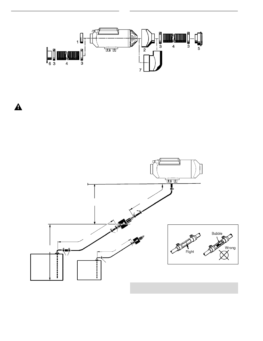
Fuel System
The fuel metering pump is the heart of the system and
must be installed properly to ensure a successful heater
operation.
Fuel System Overview
Note: Butt joints and clamps on all connections.
Optional
1. Fuel Pick-Up Pipe
2. 5.0 Rubber Connector
3. 11mm Clamp
4. 2.0mm Black Plastic Fuel Line
5. Fuel Metering Pump
6. 9mm Clamp
7. 3.5mm Rubber Connector
8. 1.5mm White Plastic Fuel Line
9. 5mm Rubber Fuel Line
Max. 2’6”
Fuel
Tank
Fuel
Tank
Max. 2’
Max. 6’6”
1
2
2
3
3
5
6
7
8
6
7
4
3
9
3
5
1
Max. 20’
Max. 6’6”
9
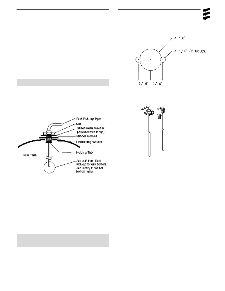
( Custom Pick-Up Pipe with NPT fitting )
• Remove an existing plug from the top of the fuel tank.
• Cut the fuel pick-up pipe to length.
• Secure the fuel pick-up pipe into position using the
combined NPT compression fitting
Note: NPT fittings are available in various sizes (Refer
to parts section).
Fuel Pick-Up Pipe Installation (Standard Pick-Up)
• Choose a protected mounting location close to the fuel
pump and heater. A spare fuel sender gauge plate pro-
vides an ideal mounting location.
• Drill the mounting holes as shown
• Cut the fuel pick-up pipe to length.
• Mount the fuel pick-up pipe as shown.
• Lower the fuel pick-up pipe (with reinforcing washer) into
the tank using the slot created by the two 1/4” holes.
• Lift the assembly into position through the 1” hole.
• Assemble the rubber washer, metal cup washer and nut.
Note: Drill the two 1/4” holes first.
NPT fitting and pipe
10
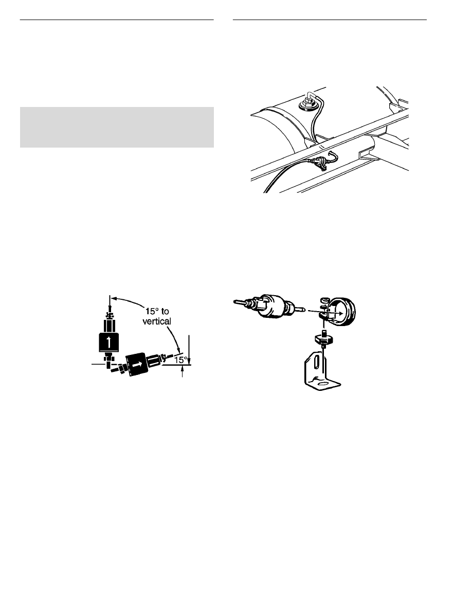
Fuel Metering Pump
• Choose a protected mounting location close to the fuel
pick-up pipe and heater.
• Using the bracket and rubber mount provided, install fuel
pump as shown
Note: Proper mounting angle of the fuel pump is
necessary to allow any air or vapor in the fuel
lines to pass through the pump rather than cause
a blockage.
Fuel Line
• Route fuel lines from the fuel pick-up pipe to the fuel
metering pump then to the heater.
• Use fuel lines provided.
• Other sizes or types of fuel lines may inhibit proper
fuel flow.
• Make proper butt joints using clamps and connector
pieces as shown on page 8
• Use a sharp utility knife to cut plastic fuel lines to avoid
burrs.
11
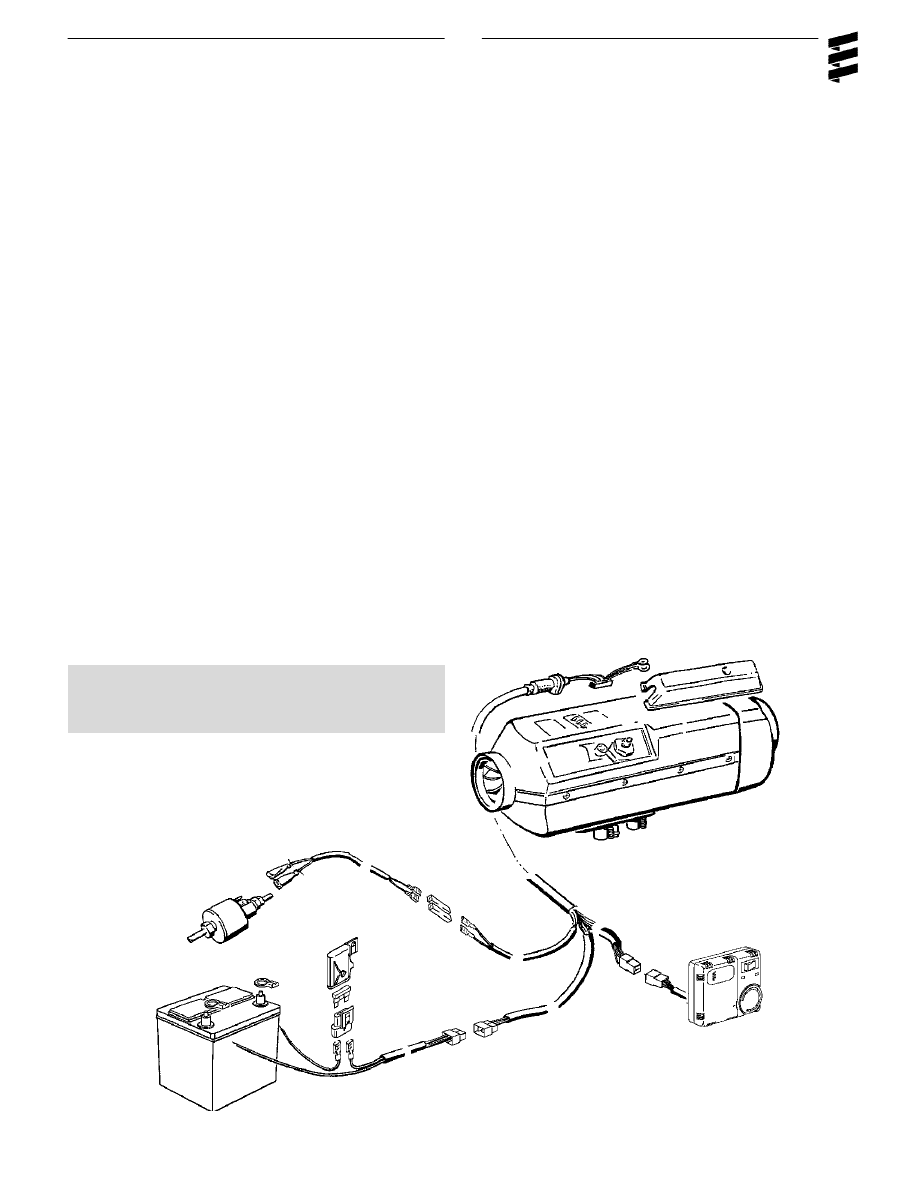
Electrical Connections
Caution:
Install power fuse only after all electrical
connections are complete.
Main Harness.......................................................................
11 core harness (red/white, green/red, blue/white, red,
w h i t e, gr ey/red, gr ey, brown, brown, brown/white and ye l l ow ) .
Connect to heater control unit (mounted in heater) using
the 14 pin connector then connect glow plug connector.
Place protective hood over glow plug and control unit & secure.
Connect to other harnesses as described for each harness.
Power Harness.....................................................................
2 core harness (red and brown).
Connect red wire to fuse holder near battery.
Connect red fuse link wire to other side of fuse holder.
Connect other end of fuse link wire directly to battery positive
post using ring terminal provided.
Connect brown wire directly to battery negative post using ring
terminal provided.
Run power harness to main harness - connect 2 pin connec-
tors
Switch Harness....................................................................
7 core harness (red, brown/white, yello w, grey, blue/white,
brown and grey/red ).
Connect to rheostat switch or thermostat (refer to switch
connection section).
Connect switch harness to main harness using 8 pin connector.
Fuel Metering Pump Harness.............................................
2 core harness (green/red and brown).
Connect to fuel metering pump using single terminals and
rubber protective boots (no polarity required).
Connect fuel metering pump harness to main harness using
two single connectors.
Note: All exposed electrical connections should be coat-
ed with protective grease, (petroleum gel,
Vaseline, etc.).
Main Harness
Thermostat
Switch Harness
Fuel Metering Pump Harness
Fuse and holder
Power Harness

12
Warning:
The exhaust is hot, keep a minimum of 2”
clearance from any heat sensitive material
Warning:
Route exhaust so that the exhaust fumes
cannot enter the passenger compartment.
Exhaust and Combustion Air Intake Connections
A 24mm flexible stainless steel exhaust pipe (39”long) and
a 20mm flexible plastic tube (39” long) for combustion air
intake are included with the heater kit. Exhaust clamps
and holders are also provided.
Caution:
Run exhaust and combustion air intakes so
they cannot be plugged by dirt, water or
snow. Ensure the outlets do not face into the
vehicle slip stream.
Keep exhaust and combustion air intake a
minimum of 12” apart.
Drill 1/8” holes where necessary to allow
water drainage.
Balance the exhaust pipe length with the
combustion air intake length.
Combustion air intake and exhaust lengths
can be shortened to a minimum of 8”.
• Attach the exhaust pipe to the exhaust outlet of the heat
exchanger
• Run to an open area to the rear or side of the vehicle so
that fumes cannot build up and enter the cab or the
combustion air inlet to the heater.
• Install protective cap.
• Attach the combustion air intake tube to the combustion
air inlet of the heater
• Once secure to the heater inlet, the intake pipe must run
to the underside of the vehicle where it will pick up clean,
fresh, moisture free air.
Exhaust (min.8”).
Operating Switches
The heater can be controlled using a Thermostat or
Rheostat type switch. It can also be accessed by a 7 day
timer with thermostat.
Thermostat
• Mount the thermostat in a location where it is easily
accessible and it’s temperature sensor is representative
of the area being heated.
• Mount using the mounting slots in it’s base.
• Connect the six core switch harness to the thermostat as
shown
Rheostat Switch
Note: When using Rheostat switch, the Return Ducting
method must be used as shown on page 7.This
allows the heater’s internal sensor to properly
monitor cab temperature.
• Mount the rheostat switch in a
location where it is easily
accessible.
• Connect the six core switch har -
ness as shown
Combustion Air Intake
(min.of 8”).
13
Heater Operation
Warning:
To prevent fire, the heater must be
switched off while filling fuel tanks.
To prevent asphyxiation, the heater must
not be operated in enclosed areas.
1
Switch On
• Switch the heater on using the room thermostat’s,
On/Off switch (1=On, 0=Off ) or the rheostat switch.
2
Start Up
On start up the indicator light illuminates and the follow-
ing sequences take place:
• Control unit does a systems check (glow plug, flame
sensor, temperature sensor, safety thermal sensor).
• Blower starts slowly and begins to accelerate.
• Glow plug is energized and starts preheating the com-
bustion chamber.
• After a short delay (approximately 15 seconds) the fuel
pump delivers fuel.
• Ignition will take place as the fuel/air mixture contact the
glow plug.
• Blower speed and fuel delivery are slowly increased.
• Once flame is established the glow plug will switch off.
• Heater will begin heating.
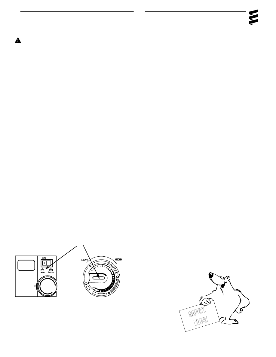
3
Temperature Setting
Using the adjusting dial, set the desired temperature
range. From 1-4
• Lowest Setting - approx. 10°C (50˚F)
• Mid - Setting - approx. 18°C (65˚F)
• Highest Setting - approx. 30°C (85˚F)
4.
Temperature Control
• The temperature is monitored constantly at the heater
intake or thermostat.
• This temperature is compared to the set temperature on
the adjusting dial.
• The heater cycles through Boost, High, Medium and
Low heat modes to maintain the desired temperature.
• If the desired temperature is exceeded while the heater
is operating in low heat mode the heater will switch off.
This is a comfort feature.
• The heater will re-start in medium heat mode once heat
is again required.
5
Switch Off
Once switched off either manually or automatically, the
heater begins a controlled cool down cycle.
• The fuel pump stops delivering fuel.
• The glow plug is re-energized for a 15 second after-glow.
• The blower continues to run for 3 minutes and automati-
cally switches off.
6
Controls and Safety Equipment
• If the heater fails to ignite within two 90 second start
attempts, a "no start" shut down occurs.
• If a flame out occurs after the heater has started, the
heater will attempt to restart.
• If repeated flame outs occur within 10 minutes the
heater will not restart.
• Overheat shut down will occur if there is a restriction of
the heating air flow (i.e. blocked inlet or outlet). The
overheat switch will automatically reset once the heater
has cooled down. Once the air flow restriction is
removed, the heater can be re-started by switching the
heater off then back on.
• If the voltage drops below 10.5 volts or rises above 15.9
volts the heater will shut down (21volts and 30 volts for
24 volt systems).
• If the glow plug circuit or fuel metering pump circuit are
interrupted the heater will
not start.
• The blower motor is checked on
start up and every 4 minutes.
Shut down will occur if
the blower does not start or
maintain proper speed.
Operation
indicating light
High
Low

14
Operational Flow Chart
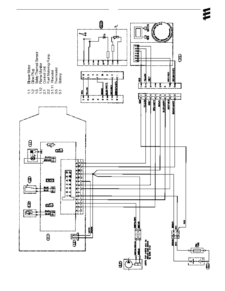
15
Wiring Diagram D1LCcompact
Models:
25 1976 05 (12v)
25 1977 05 (24v)
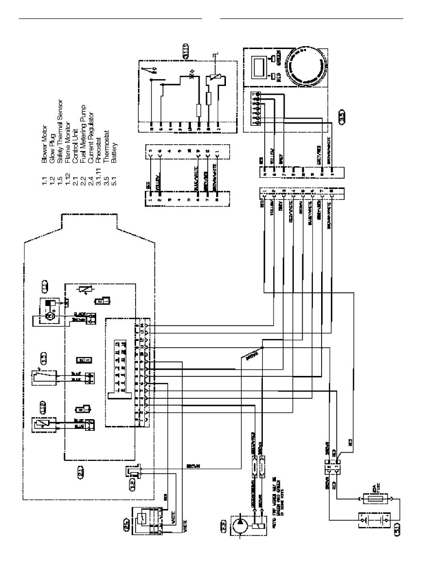
16
Wiring Diagram D1LCcompact
Models:
25 1965 05 (12v)
25 1966 05 (24v)

17
Models:
25 1895 05 (12v)
25 1896 05 (24v)
Wiring Diagram D1LCcompact

18
Maintenance, Troubleshooting and Repairs
Recommended Periodic Maintenance
• Remove the glow plug and inspect for carbon build up.
Clean or replace.
• Remove the glow plug screen and inspect for carbon
build up. Clean or replace. If cleaning is required, use
brass brush (Espar part number CA0 05 003).
• Make sure vent hole is open. Espar recommends the
use of non detergent 100% volatile carburetor
cleaner and an air gun will also help. Remove loose
carbon from the glow plug chamber.
• Inspect the ducting, the air intake screen and air outlet
for restriction or blockage.
• Inspect combustion air intake and exhaust for block-
age.
• Run your heater and check for proper operation during
regular preventative maintenance throughout the year.
• Maintain your batteries and all electrical connections in
good condition. With insufficient power the heater will
not start. Low and high voltage cutouts will shut the
heater down automatically.
• Use fuel suitable for the climate (see engine manufac-
turers recommendations). Blending used engine oil with
diesel fuel is not permitted.
Basic Troubleshooting
Check LIst:
What happens when the heater is switched on and ....
Heater does not ignite
1 Blower motor does not run
Check:
- Fuse in power harness.
- Power to control unit.
- Power to switch.
- Electrical connections.
2 Blower motor runs approximately 20 seconds and then
shuts off
Check:
- Ensure voltage at control unit remains
above 9.5 volts during start up with glow
plug circuit on.
3 Blower motor runs/fuel metering pump starts and then
shuts down after two 90 second start up cycles
Check:
- Fuel lines and fuel filter.
- Fuel quantity.
- Combustion air or exhaust tube blockage.
4 Blower motor runs/no fuel metering pump
Check:
- For electrical pulses at fuel metering
pump.
- If pump is frozen.
- Blocked fuel line.
Heater ignites
1 Shuts down at random
Check:
- Fuel metering pump quantity.
- Possible overheat.
- Control unit input voltage.
2 Heater smokes and carbons up
Check:
- Exhaust pipe blocked.
- Combustion air intake blocked.
- Exhaust entering combustion air intake
pipe.
- Short cycling, rapid on/off operation.
- Fuel system.
- Fuel metering pump quantity.
- Motor rpm.
19
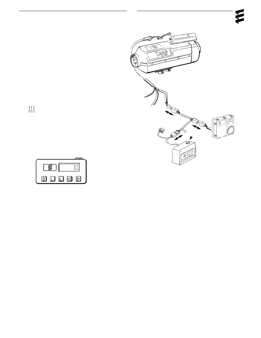
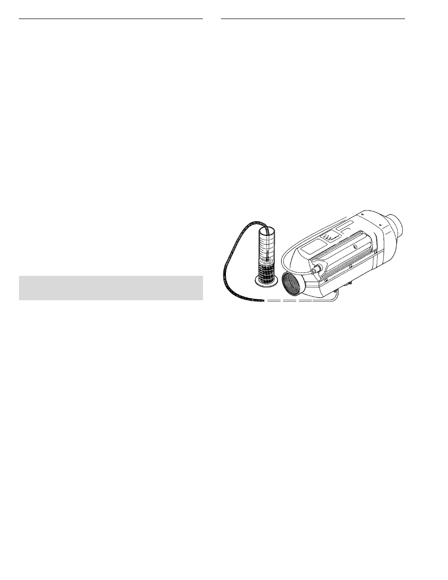
Self Diagnostics
The heater is equipped with self diagnostic capability. To
retrieve information on the heaters last 5 faults, a
retrieval device is required (part # CA1 05 020).
Connect the fault code retrieval device as shown
Equipment Face and Controls
Symbols that are seen on the display face are as follows:
AF
Actual fault.
F1-F5
Up to five stored faults can be
accessed. The AF and F1 are the
same number.
This sign is displayed when the
heater is in operation.
DIAG
The word (Diagnostic) will come on
when the diagnostic number is
requested.
000
Three digit diagnostic fault code
number.
• Switch the fault code retrieval device on and wait 10 sec -
onds.
• Press the "D" button.
• Wait 3-5 seconds for the current fault code to appear
(AF).
• To review the previous faults use the arrow buttons (F1=
Most Recent, F5= Oldest).
• To erase the faults that are in memory press both "L"
keys at the same time.
• Consult the fault code chart for code number descrip-
tions.
Retrieval Device
On/Off

20
Note: If there are no heater faults, the heater will go
through a normal start cycle and regulate based
on thermostat setting.
Fault Code
Fault Description
Causes / Repair
000
Normal Operation
001
Warning - overvoltage
Check vehicle charging system.
002
Warning - under voltage
Check batteries and connections.
004
Warning - short in blower signal
Check for short between pin 1 to blower relay. If no shor t
exists replace control unit.
005
Warning - short circuit in anti-theft
Check for short between pin 2 and alarm relay.
alarm output
009
TRS - shut down
Check for change of signal from (+) to (-) at pin 10 or a (+)
signal at pin 12.
010
Overvoltage
Check voltage between terminals 9 and 11.
This must be less than 15.9 volts
(15.2 volts with glow plug on).
Check vehicle charging system.
011
Undervoltage shut down
Check voltage between control unit pins 9 and 11. This must
be greater than 10.5 volts (9.5 volts with glow plug on).
Check batteries and connections.
012
Overheat
Check for possible causes of overheat.
Check overheat switch resistance values.
(see component value chart).
013
Overheat at flame sensor
Flame sensor senses temperature above 340°C (resistance
value above 2270
Ω
). Check flame sensor resistance
values and overheat switch resistance values
(see component value chart ) .
015
Too many overheats
Control unit limits heater to 3 consecutive overheats (fault
code12,13). Remove cause of over heat. Reset control unit
using control unit tester or fault code retrieval device to
unlock control unit.
020
Open circuit - glow plug
Check glow plug for break in coils.
Check resistance across glow plug leads
(1-2
Ω
). Check for continuity between pins 6 and 9. If afore
mentioned checks okay, replace control unit.
021
Short circuit - glow plug
Check glow plug for short across coils.
Check pin 6 to glow plug for short.
If glow plug short detected, replace glow plug.
If afore mentioned checks okay replace control unit
025
Diagnostics ouput shor t
Check for short between pin 4 and diagnostics and
output connection.
033
Burner motor speed deviation
Motor speed varies from specification by more than 10%
for longer than 30 seconds . If too slow, check for
restriction, and check for shor t in motor circuit or control
unit. If none found, replace blower. If too fast, check for
damage to magnetic sensor control on control unit.
Replace blower motor if damaged.
Replace control unit otherwise.

21
Fault Code
Fault Description
Causes / Repair
047
Short circuit - fuel metering pump
Check for short between pin 3 and fuel metering pump.
Test fuel metering pump.
048
Open circuit - fuel metering pump
Check for open circuit between pins 3 and fuel
metering pump.
050
Too many no start attempts
Control unit restricts heater to 10 start
attempts (20 starts if no flame is detected
during start attempts). Check fuel, glow plug,
combustion air and exhaust flow. Use control unit tester
or fault code retrieval device to unlock control unit.
051
Faulty flame recognition
Allow heater to cool 15 minutes then try restart.
Check flame sensor resistance value.
052
No start safety time exceeded
No flame detected on start attempt.
Temperature at flame sensor <100°C (1380
Ω
).
Check flame sensor resistance values. Check
fuel, glow plug, combustion air and exhaust flows .
053
Flame cutout in boost mode
Heater has started successfully the flame has
extinguished. Check fuel supply. Check combustion air
and exhaust flow. Check flame sensor resistance value.
054
Flame cutout in high mode
Heater has started successfully the flame has
055
Flame cutout in medium mode
extinguished. Check fuel supply.
056
Flame cutout in low mode
Check combustion air and exhaust flow.
Check flame sensor resistance value.
060
Open circuit - external temperature
Temperature sensor detects a value beyond it's range
sensor
Check connections.
061
Short circuit - external temperature
Check sensor resistance between pins 8 and 13
sensor
> 2800
Ω
- open
< 280
Ω
- short
062
Open circuit - set point
Potentiometer values outside of range
poteniometer (control switch)
Check resistance between pins 7 and 13.
063
Short circuit - set point
> 2800
Ω
- open
poteniometer (control switch)
< 280
Ω
- short
Normal range 1750 - 2080
Ω
(+/- 80).
064
Open circuit - flame sensor
Sensor is sensing value outside of range
065
Short circuit - flame sensor
> 3200
Ω
- open
071
Open circuit - overheat sensor
< 200
Ω
- shor t
090
Control unit defect
Internal failure. Replace control unit.
091
External voltage disturbance
Check vehicle charging system.
092
Control unit defective
Internal failure. Replace control unit.
093
094
096
Control unit defective (internal
Internal failure.
temperature sensor)
Replace control unit or use external sensor.
097
Control unit defective (power failure)
Internal failure. Replace control unit.
22
Component Specification Chart
Component values given are reference numbers only
(at room temperature). Actual component values may
vary ±10%.
Resistance Values
Component
Resistance
Location
Wire Colors
Glow Plug
1
Ω
Glow Plug
White, Brown
Motor
.5
Ω
From Control Unit
Black, Brown
Flame Sensor
1.1 K
Ω
From Control Unit
Blue, Blue
Overheat Sensor
1.1 K
Ω
From Control Unit
Blue, Blue
Fuel Pump
10.0
Ω
Fuel Metering Pump
Grn/Brn,Grn
Rheostat (Range)
1.8-2.2 K
Ω
Thermostat Pins 1,2
Brn/Wt,Gr/Rd
Temperature Sensor (Range)
1.8-2.2 K
Ω
Thermostat Pins 1,T
Brn/Wt ,Grey
Fuel Quantity Test
The fuel quantity should be tested if the heater has difficulty
starting or maintaining a flame:
Preparation
• Detach the fuel line from the heater.
• Insert the fuel line into a measuring glass (10 cc).
• Switch the heater on and allow fuel system to bleed out
air for approx. 20 seconds.
• Switch the heater off and empty the measuring glass.
Measurement
• Switch heater on.
• Hold the fuel line in the measuring glass while fuel is
being delivered.
• The pump will stop automatically after delivering fuel for
90 seconds.
• Once fuel pump stops, switch heater off.
Evaluation
• Read the amount of fuel delivered.
• Fuel quantity should be between 3.4ml and 4.65ml.
• If the fuel quantity is outside this range, check for and
remove any restriction in fuel system or replace the fuel
metering pump. (Check screen in suction side of pump)
Note: The fuel quantity is not affected by voltage
variances.
Motor Speeds
Boost
5,000 RPM
High
4,400 RPM
Medium
3,000 RPM
Low
3,000 RPM
Recirculation
1,000 RPM (when using internal
temperature sensor)
Exhaust Gas
• CO2 concentration in exhaust gas when heater is run-
ning
in High heat mode 6-10%.
• Smoke test value from exhaust gas when heater is
running in High heat mode <4.
23
Note: Ensure seam of screen and tab do not block the
air vent hole or fuel port.
Fuel port &
Air vent hole
Control Unit
Repair Steps
Inspection, Removal and Replacement of the:-
..Glow Plug
..Atomizer Screen
..Control Unit
..Heater Casing Disassembly
..Overheat Sensor
..Flame Sensor
..Blower Removal and Replacement
..Heat Exchanger Cleaning
Glow Plug Removal, Inspection and Replacement
• Remove glow plug connector.
• Remove glow plug.
• Inspect coils for carbon build up, breaks or metal fatigue.
• Clean or replace if necessar y.
• Re-install in reverse order using a new gasket.
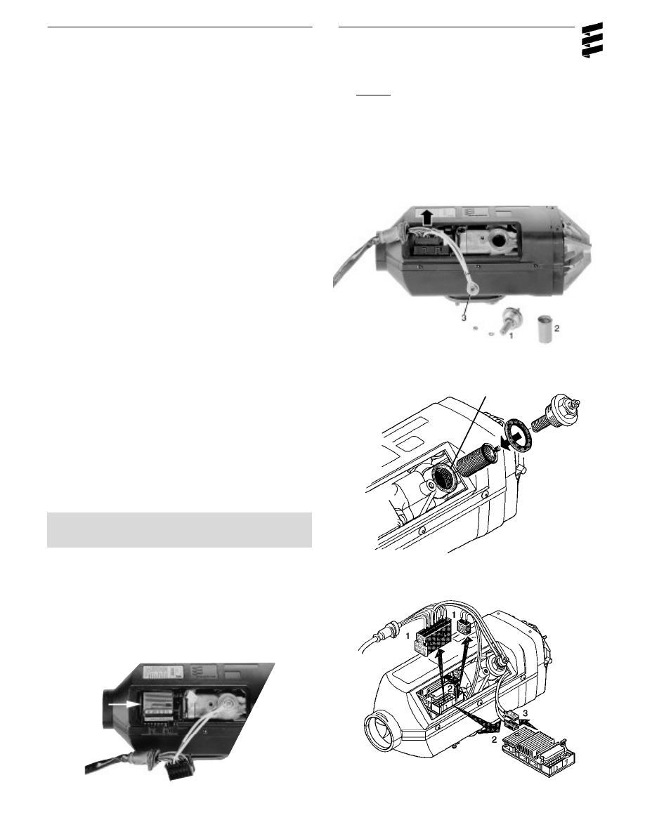
Atomizer Screen Removal, Inspection and
Replacement
• Remove atomizing screen using the metal tab and a pair
of pliers.
• Clean screen using varsol, brass wire brush and com-
pressed air.
• Inspect screen for deterioration and replace if necessary.
• Clean the glow plug chamber to remo ve carbon build up.
• Ensure air vent hole and fuel port are clear.
• Re-install fuel screen.
Disconnect
1.Glow Plug
2.Atomizer Screen
3.Glow Plug Connector
Caution:
Remove power from the heater prior
to any disassembly by unplugging main
connection or removing main fuse.
Control Unit Removal and Replacement
• Unplug main harness and motor connectors. (1)
• To remove Control Unit, unlock and slide out. (2)
• Unplug overheat switch and flame sensor connectors. 3
• Re-install in reverse order.

24
Overheat Sensor
Flame Sensor
Heater Casing Disassembly
• Remove internal hex screw and cap.
• Pry off air outlet hood using a flat screw driver.
• Remove rivets by punching center pin through and pry-
ing out base.
• Remove rubber seal at base of heat exchanger.
• Separate outer casing.
• Re-assemble in reverse order using new rivets.
1.Outer Casing
2.Air Outlet Hood
3.Cap with Internal Hex Screw
Overheat Sensor Replacement
• Using a small flat screw driver, pry off holding clips.
• Lift sensor from mounting studs .
• Install replacement sensor using new holding clips.
• Ensure the sensor is securely mounted against heat
exchanger.
Flame Sensor Replacement
• Using a small flat screw driver, pry off holding spring.
• Remove spring and flame sensor.
• Install replacement sensor using a new mounting spring.
• Ensure the sensor is securely mounted against heat
exchanger
25
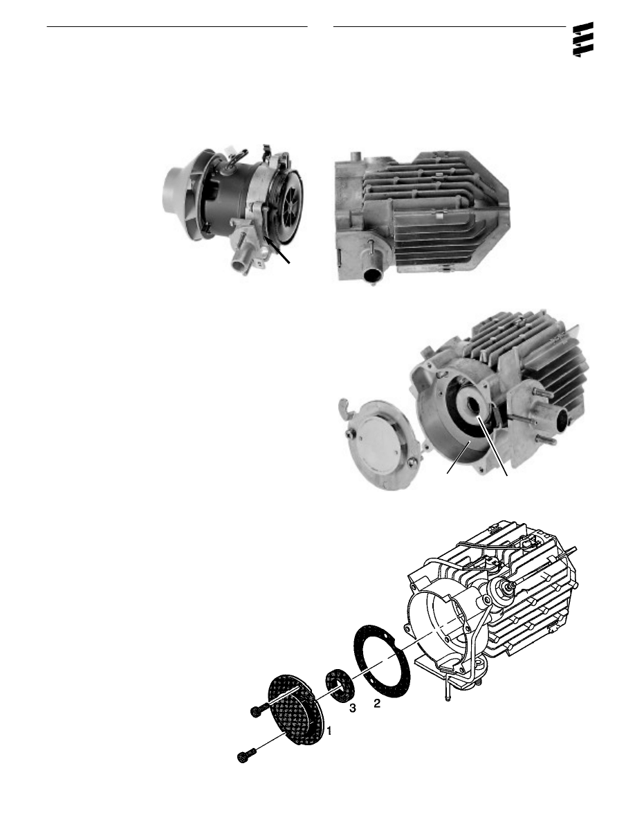
Blower Removal and Replacement
• Remove four mounting screws.
• Separate blower from heat exchanger.
• Re-assemble using new gasket.
Gasket
Heat Exchanger
Blower
Heat Exchanger Cleaning and Inspection
• Remove two mounting screws and baffle plate
• Remove and replace gasket.
• Clean excessive carbon from inside heat exchanger
using a brass wire brush, varsol and compressed air.
• Inspect felt ring and replace if damaged.
• Re-assemble in reverse order using new gaskets.
1
2
3
1 Baffle Plate
2 Gasket
3 Felt Ring
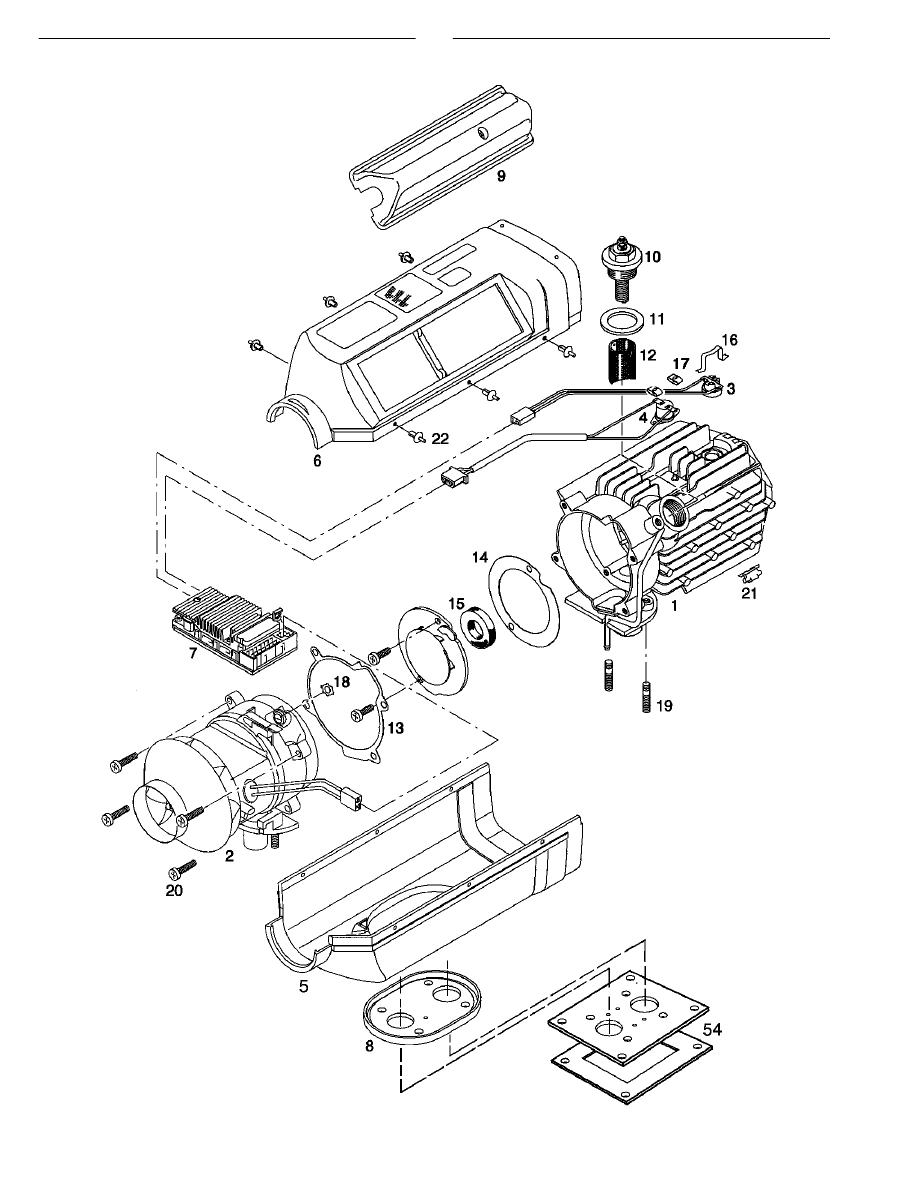
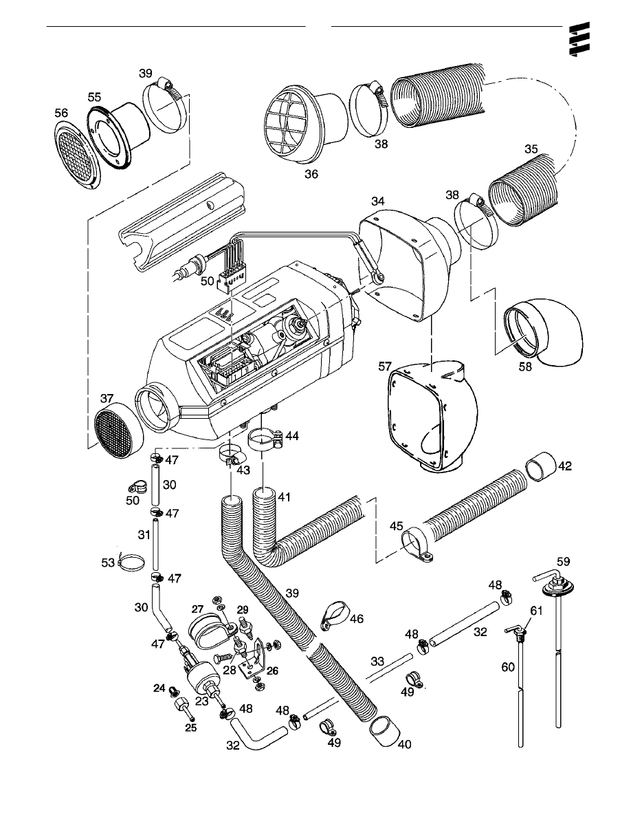
26
D1LCcompact
Service Parts Diagram
27
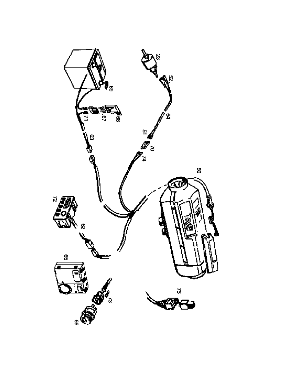
28
Parts continued.

29
Parts List D1LC compact
Ref. No.
Description
Part Number
1
Heat exchanger
25 1774 99 06 00
•
•
•
•
•
•
2
Combustion air blower
12 Volt 25 1895 99 20 00
•
•
•
24 Volt 25 1896 99 20 00
•
•
•
3
Flame sensor
25 1895 99 35 00
•
•
•
•
•
•
4
Safety thermal sensor
25 1895 41 00 00
•
•
•
•
•
•
5
Lower half of casing
25 1895 01 01 00
•
•
•
•
•
•
6
Upper half of casing
25 1895 01 06 00
•
•
•
•
•
•
7
Control unit
12 Volt 25 1895 50 00 13
•
•
12 Volt 25 1976 99 51 01
•
24 Volt 25 1977 99 51 01
•
•
•
8
Flange seal
25 1774 01 00 02
•
•
•
•
•
•
9
Cable cover
25 1895 01 02 00
•
•
•
•
•
•
10
Glow plug
12 Volt 25 1830 01 01 00
•
•
•
24 Volt 25 1831 01 01 00
•
•
•
11
Seal ring
25 1830 01 01 01
•
•
•
•
•
•
12
Glow plug screen
25 1688 06 04 00
•
•
•
•
•
•
13
Gasket, blower
25 1688 01 00 06
•
•
•
•
•
•
14
Gasket, heat exchanger
25 1688 06 00 03
•
•
•
•
•
•
15
Seal ring, heat exchanger
25 1688 06 00 06
•
•
•
•
•
•
16
Spring, flame sensor
25 1895 01 00 03
•
•
•
•
•
•
17
Clip, safety switch
171 42 080
•
•
•
•
•
•
18
Serrated ring
171 19 254
•
•
•
•
•
•
19
Grub screw M6x20 DIN 835
106 10 022
•
•
•
•
•
•
20
Fillister head bolt M5x20
103 10 461
•
•
•
•
•
•
21
U-Clip
25 1688 01 00 03
•
•
•
•
•
•
22
Rivet, black plastic
131 31 051
•
•
•
•
•
•
23
Fuel metering pump
12 Volt 25 1830 45 00 00
•
•
•
24 Volt 25 1831 45 00 00
•
•
•
24
Fuel screen
20 1312 00 00 06
•
•
•
•
•
•
25
Hose connection
20 1621 45 00 00
•
•
•
•
•
•
26
Angle bracket
20 1348 03 00 02
•
•
•
•
•
•
27
Clamp for fuel metering pump
152 00 144
•
•
•
•
•
•
28
Rubber mount 6mm
20 1185 00 00 01
•
•
•
•
•
•
29
Rubber mount
20 1673 80 01 01
•
•
•
•
•
•
30
Fuel hose 3.5mm ID
360 75 300
•
•
•
•
•
•
31
Plastic fuel line 1.5mm ID
090 31 118
•
•
•
•
•
•
32
Fuel hose 5mm ID
360 75 350
•
•
•
•
•
•
33
Plastic fuel line 2mm ID
090 31 125
•
•
•
•
•
•
34
Straight outlet hood 60mm
25 1688 80 03 00
•
•
•
•
•
•
35
Flexible air hose 60mm ID
10 2114 31 00 00
•
•
•
•
•
•
36
Deflector 60mm
20 1577 89 06 00
•
•
•
•
•
•
37
Safety screen
25 1688 80 06 00
•
•
•
•
•
•
38
Clamp 46mm-70mm
CA1 10 047
•
•
•
•
•
•
39
Air intake hose 20mm ID
360 00 099
•
•
•
•
•
•
40
End sleeve with crossbar
25 1688 80 12 01
•
•
•
•
•
•

30
Ref. No.
Description
Part Number
41
Flexible exhaust tube 24mm ID
360 61 299
•
•
•
•
•
•
42
End sleeve 24mm
25 1482 80 00 01
•
•
•
•
•
•
43
Clamp 16mm-25mm
10 2064 01 60 25
•
•
•
•
•
•
44
Clamp 26mm
152 61 102
•
•
•
•
•
•
45
"C" Clamp 28mm
152 10 051
•
•
•
•
•
•
46
"C" Clamp 25mm
152 10 048
•
•
•
•
•
•
47
Clamp 9mm
10 2063 00 90 98
•
•
•
•
•
•
48
Clamp 11mm
10 2063 01 10 98
•
•
•
•
•
•
49
"C" Clamp 10mm
152 00 139
•
•
•
•
•
•
50
Main harness
CA1 60 105
•
•
CA1 60 107
•
•
CA1 60 120
•
•
51
Terminal 18 AWG
CA1 90 060
•
•
•
•
•
•
52
Rubber boot
320 31 120
•
•
•
•
•
•
53
Cable ties 197mm
CA1 00 005
•
•
•
•
•
•
54
Mounting plate with hardware & seal
CA0 00 019
•
•
•
•
•
•
55
Flange for outlet grill
20 1577 89 06 01
•
•
•
•
•
•
56
Plastic Screen 60mm
22 1000 01 00 01
•
•
•
•
•
•
* 57
90° Air outlet hood
25 1688 89 01 01
•
•
•
•
•
•
* 58
90° Bend
25 1688 89 00 01
•
•
•
•
•
•
59
Standard fuel pick up pipe 2mm
CA0 12 056
•
•
•
•
•
•
* 60
Fuel pick up pipe (Compression fitting type)
CA0 12 042
•
•
•
•
•
•
* 61
Compression fittings 1/4” NPT
CA0 12 044
•
•
•
•
•
•
3/8” NPT
CA0 00 031
•
•
•
•
•
•
1/2” NPT
CA0 12 005
•
•
•
•
•
•
62
Switch/Thermostat harness (15’)
CA1 70 111
•
•
CA1 70 120
•
•
•
•
63
Power harness (13’)
CA1 65 106
•
•
•
•
•
•
64
Fuel metering pump harness (20’)
CA1 75 015
•
•
•
•
•
•
65
Thermostat
12 Volt 301 00 154
•
•
•
•
•
•
24 Volt 301 00 153
•
•
•
•
•
•
* 66
Operating switch (rotary)
12 Volt 25 1895 71 00 00
•
•
•
•
•
•
24 Volt 25 1896 71 00 00
•
•
•
•
•
•
67
Blade fuse (25A)
204 00 089
•
•
•
•
•
•
68
Fuse holder with terminals
CA1 07 001
•
•
•
•
•
•
69
3/8” Ring terminal 10-12G
CA1 90 014
•
•
•
•
•
•
70
Plug & socket connector
206 00 040
•
•
•
•
•
•
71
Terminals
CA1 90 043
•
•
•
•
•
•
*72
7 day timer
22 1000 30 40 00
•
•
•
•
•
•
73
Terminals
CA1 900 21
•
•
•
•
•
•
74
Terminals for fuel metering pump 18 AWG
CA1 90 060
•
•
•
•
•
•
75
Glow plug regulator
12 Volt 25 1830 30 01 00
•
24 Volt 25 1966 30 01 00
•
Operator’s guide (not shown)
615 101 0296
•
•
•
•
•
•
D1LCc North American manual (not shown)
610 101 0396
•
•
•
•
•
•
Operator’s tape (not shown)
625 101 0893
•
•
•
•
•
•
Fault code retrieval device (shown pg. 21)
CA1 05 020
•
•
•
•
•
•
*
indicates optional features

1st. Printing - October 1996
Printed in Canada
P/N: 610 - 101- 0498
Espar Products, Inc.
6435 Kestrel Road
Mississauga, Ontario
Canada L5T 1Z8
17370 N. Laurel Park Drive
Suite 400E
Livonia, Michigan
United States
48152
Canada (Tel):
905-670-0960
800-668-5676
Fax:
905-670-0728
U.S. (Tel):
800-387-4800
A member of the Worldwide
Eberspächer
Group of Companies
Wyszukiwarka
Podobne podstrony:
Comparative study based on exergy analysis of solar air heater collector using thermal energy storag
D 1 LC COMPACT
Simple Retrofitted Flat Plate Solar Water and Air Heaters
HEATER & AIR CONDITIONER
Hygromatic Heater Compact broszura
SR 8 Adaptive Air Conditioning ULA[1]
DIELEKTRYKI cz1 AIR
Popular Mechanics Finding And Fixing Water And Air Leaks
Dawning Star Terraformer 10 Eotian Air Carriers
Prog wyk TMM AiR 2010
Poprawkowy AiR 2008 2009
control el heater pl
egzamin air 08092010 studenci
programowanie020, AiR, semestr II
Koła 2010, pwr, air, semestr 3, Mechanika analityczna, KOŁO ĆWICZENIA (matek sp)
tab imip a4, AiR WIP, IV semestr, PRZTS Przetwórstwo tworzyw sztucznych, projekt
więcej podobnych podstron