
SECTION : 9D
WIPERS/WASHER SYSTEMS
CAUTION : Disconnect the negative battery cable before removing or installing any electrical unit or when a tool
or equipment could easily come in contact with exposed electrical terminals. Disconnecting this cable will help
prevent personal injury and damage to the vehicle. The ignition must also be in LOCK unless otherwise noted.
TABLE OF CONTENTS
SPECIFICATIONS
9D–1
. . . . . . . . . . . . . . . . . . . . . . . . . .
FASTENER TIGHTENING SPECIFICATIONS
9D–1
.
SCHEMATIC AND ROUTING DIAGRAMS
9D–2
. . . . .
WIPERS AND WASHER SYSTEM (NOTCHBACK) 9D
–2
WIPERS AND WASHER SYSTEM (HATCHBACK) 9D
–3
DIAGNOSIS
9D–4
. . . . . . . . . . . . . . . . . . . . . . . . . . . . . . . .
WINDSHIELD WIPERS
9D–4
. . . . . . . . . . . . . . . . . . . .
WINDSHIELD WASHER SYSTEM
9D–8
. . . . . . . . . . .
REAR WINDOW WIPER (HATCHBACK AND
WAGON)
9D–9
. . . . . . . . . . . . . . . . . . . . . . . . . . . . . . .
REAR WINDOW WASHER SYSTEM (HATCHBACK
AND WAGON)
9D–11
. . . . . . . . . . . . . . . . . . . . . . . . .
MAINTENANCE AND REPAIR
9D–12
. . . . . . . . . . . . . .
ON–VEHICLE SERVICE
9D–12
. . . . . . . . . . . . . . . . . . . .
WINDSHIELD WIPER ARM
9D–12
. . . . . . . . . . . . . . . .
WINDSHIELD WIPER MOTOR
9D–12
. . . . . . . . . . . . .
WINDSHIELD WIPER BLADE
9D–14
. . . . . . . . . . . . . .
WINDSHIELD WIPER BLADE INSERT
9D–14
. . . . .
WINDSHIELD WASHER RESERVOIR
9D–15
. . . . . .
WINDSHIELD WASHER PUMP(S)
9D–17
. . . . . . . . . .
WINDSHIELD WASHER NOZZLES
9D–18
. . . . . . . . .
WINDSHIELD WASHER HOSES
9D–18
. . . . . . . . . . .
REAR WINDOW WIPER ARM
9D–20
. . . . . . . . . . . . .
REAR WINDOW WIPER MOTOR (HATCHBACK) 9D–
20
REAR WINDOW WIPER MOTOR (WAGON)
9D–21
.
REAR WINDOW WASHER NOZZLE (HATCHBACK) 9
D–22
GENERAL DESCRIPTION AND SYSTEM
OPERATION
9D–24
. . . . . . . . . . . . . . . . . . . . . . . . . . . . .
WINDSHIELD WIPER SYSTEM
9D–24
. . . . . . . . . . . .
WINDSHIELD WASHER SYSTEM
9D–24
. . . . . . . . . .
REAR WINDOW WIPER/WASHER SYSTEM
9D–24
SPECIFICATIONS
FASTENER TIGHTENING SPECIFICATIONS
Application
N
S
m
Lb–Ft
Lb–In
Front Wheel Well Splash Shield Bolts
1.5
–
13
Washer Fluid Reservoir Bolts
8
–
71
Wiper Arm Linkage Nut
5
–
44
Wiper Arm Nut
11
–
97
Wiper Motor Bolts
8
–
71
9D – 2
I
WIPERS/WASHER SYSTEMS
DAEWOO V–121 BL4
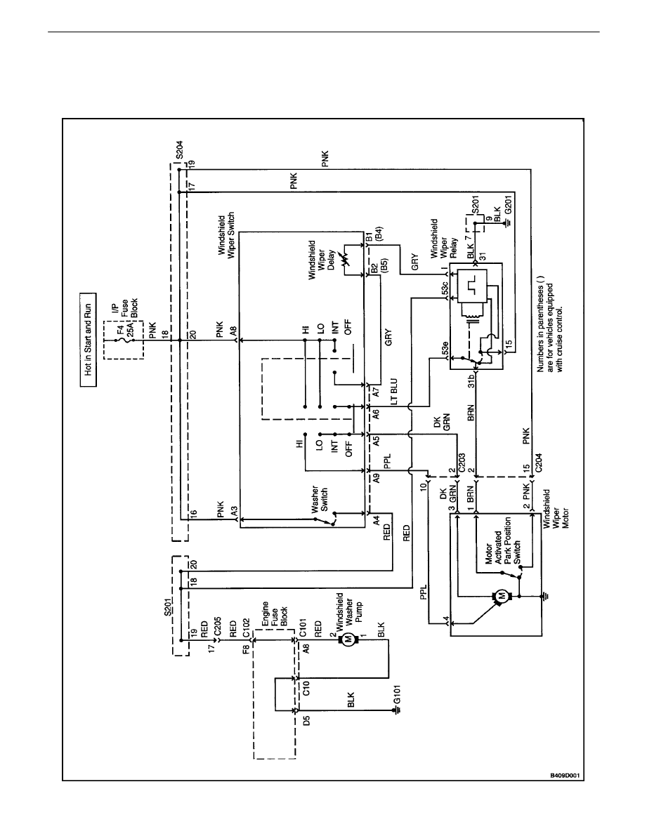
SCHEMATIC AND ROUTING DIAGRAMS
WIPERS AND WASHER SYSTEM (NOTCHBACK)
WIPERS/WASHER SYSTEMS 9D – 3
DAEWOO V–121 BL4
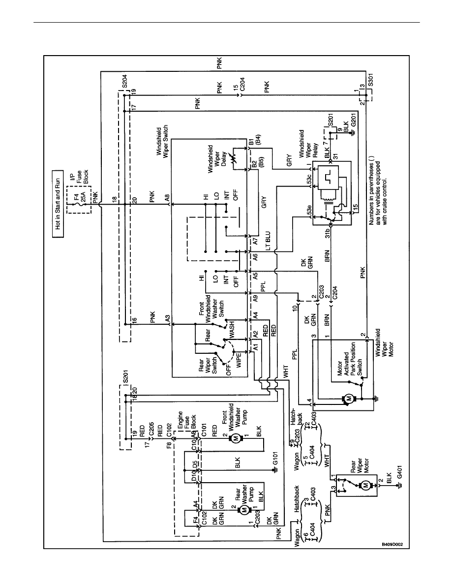
WIPERS AND WASHER SYSTEM (HATCHBACK)

9D – 4
I
WIPERS/WASHER SYSTEMS
DAEWOO V–121 BL4
DIAGNOSIS
WINDSHIELD WIPERS
Windshield Wipers Do Not Work At Any Speed
Step
Action
Value(s)
Yes
No
1
Check fuse F4.
Is fuse F4 blown?
Go to Step 2
Go to Step 3
2
1. Check for a short circuit and repair it, if neces-
sary.
2. Replace the fuse.
Is the repair complete?
System OK
3
Check the voltage at fuse F4.
Is the voltage equal to the specified value?
11–14 v
Go to Step 5
Go to Step 4
4
Repair the open power supply circuit to fuse F4.
Is the repair complete?
System OK
5
1. Disconnect the wiper motor connector.
2. Turn the ignition ON.
3. Turn the wiper switch to HI.
4. Check the voltage at the wiper motor connector
terminal 6.
Is the voltage equal to the specified value?
11–14 v
Go to Step 6
Go to Step 7
6
Replace the wiper motor.
Is the repair complete?
System OK
7
1. The wiper switch is still disconnected.
2. Turn the ignition ON.
3. Check for battery voltage at the wiper switch
connector terminal A8.
Is the voltage equal to the specified value?
11–14 v
Go to Step 9
Go to Step 8
8
Repair the open circuit between the wiper switch
connector terminal A8 and fuse F4.
Is the repair complete?
System OK
9
1. The wiper switch is still disconnected.
2. Turn the wiper switch to HI.
3. Use an ohmmeter to check for continuity be-
tween wiper switch terminal A8 and A9.
Does the ohmmeter indicate the specified value?
[
0
W
Go to Step 11
Go to Step 10
10
Replace the wiper switch.
Is the repair complete?
System OK
11
Repair the open circuit between the wiper switch and
the wiper motor.
Is the repair complete?
System OK

WIPERS/WASHER SYSTEMS 9D – 5
DAEWOO V–121 BL4
Wipers Do Not Work On HI Speed, LO Speed OK
Step
Action
Value(s)
Yes
No
1
1. Turn the ignition ON.
2. Turn the wiper switch to HI.
3. Check the voltage at the wiper motor connector
terminal 4.
Is voltage equal to the specified value?
11–14 v
Go to Step 2
Go to Step 3
2
Replace the wiper motor.
Is the repair complete?
System OK
3
1. Disconnect the wiper switch.
2. Turn the wiper switch to HI.
3. Use an ohmmeter to check for continuity be-
tween wiper switch terminal A8 and A9.
Does the ohmmeter indicate the specified value?
[
0
W
Go to Step 5
Go to Step 4
4
Replace the wiper switch.
Is the repair complete?
System OK
5
Repair the open circuit between wiper switch con-
nector terminal A9 and wiper motor connector termi-
nal 4.
Is the repair complete?
System OK
Wipers Do Not Work On LO Speed, HI Speed OK
Step
Action
Value(s)
Yes
No
1
1. Turn the ignition ON.
2. Turn the wiper switch to LO.
3. Check the voltage at the wiper motor connec-
tor, terminal 3.
Is the voltage equal to the specified value?
11–14 v
Go to Step 2
Go to Step 3
2
Replace the wiper motor.
Is the repair complete?
System OK
3
1. Disconnect the wiper switch.
2. Turn wiper switch to LO.
3. Use an ohmmeter to check for continuity be-
tween wiper switch terminal A8 and A5.
Does the ohmmeter indicate the specified value?
[
0
W
Go to Step 5
Go to Step 4
4
Replace the wiper switch.
Is the repair complete?
System OK
5
Repair the open circuit between wiper switch con-
nector terminal A5 and wiper motor connector termi-
nal 3.
Is the repair complete?
System OK

9D – 6
I
WIPERS/WASHER SYSTEMS
DAEWOO V–121 BL4
Wipers Do Not Work On Intermittent (INT), Other Speeds OK
Step
Action
Value(s)
Yes
No
1
1. Turn the ignition ON.
2. Use a voltmeter to test the voltage at wiper
relay connector terminal 15.
Is voltage equal to the specified value?
11–14 v
Go to Step 3
Go to Step 2
2
Repair the open circuit between the wiper relay con-
nector terminal 15 and fuse F4.
Is the repair complete?
System OK
3
1. Turn the ignition on.
2. Turn the wiper switch to INT.
3. Check the voltage at wiper relay connector ter-
minal I.
Does the voltmeter indicate a voltage equal to the
specified value?
11–14 v
Go to Step 7
Go to Step 4
4
Check for an open circuit between wiper switch con-
nector terminal A7 and wiper relay connector termi-
nal I.
Is there an open circuit?
Go to Step 6
Go to Step 5
5
Replace the wiper switch.
Is the repair complete?
System OK
6
Repair the open circuit between wiper switch con-
nector terminal A7 and wiper relay connector termi-
nal I.
Is the repair complete?
System OK
7
1. Turn the ignition on.
2. Turn the wiper switch to INT.
3. Check for pulsing voltage at wiper switch con-
nector terminal A6.
Does the voltmeter indicate a pulsating voltage
equal to the specified value?
11–14 v
Go to Step 11
Go to Step 8
8
Using an ohmmeter, check the resistance between
ground and the wiper relay connector terminal 31.
Is resistance equal to the specified value?
[
0
W
Go to Step 10
Go to Step 9
9
Repair the open ground circuit.
Is the repair complete?
System OK
10
Replace the wiper relay.
Is the repair complete?
System OK
11
1. Ignition ON.
2. Turn the wiper switch to INT.
3. Backprobe to check the voltage at the wiper
switch connector terminal A5.
Does the voltmeter indicate a pulsating voltage
equal to the specified value?
11–14 v
Go to Step 12
Go to Step 13
12
Replace the wiper relay.
Is the repair complete?
System OK
13
Repair the open circuit between the wiper switch and
the wiper relay.
Is the repair complete?
System OK

WIPERS/WASHER SYSTEMS 9D – 7
DAEWOO V–121 BL4
Windshield Wipers Do Not Return To Park Position
Step
Action
Value(s)
Yes
No
1
1. Turn the ignition ON.
2. Check the voltage at the wiper motor connector
terminal 2.
Is the voltage equal to the specified value?
11–14 v
Go to Step 3
Go to Step 2
2
Repair the open circuit between the wiper motor
connector terminal 2 and fuse F4.
Is the repair complete?
System OK
3
1. Turn the wiper switch to HI.
2. While turning the wiper switch OFF, check the
voltage at the wiper motor connector terminal
1.
Is the specified voltage indicated when the wiper
switch is turned OFF?
11–14 v
Go to Step 5
Go to Step 4
4
Replace the wiper motor.
Is there an open circuit?
System OK
5
1. Disconnect the wiper relay.
2. Check continuity between wiper relay terminal
31b and 53e.
Does the ohmmeter indicate the specified value?
[
0
W
Go to Step 6
Go to Step 7
6
Repair the open circuit between the wiper motor and
the wiper relay.
Is the repair complete?
System OK
7
Replace the wiper relay.
Is the repair complete?
System OK

9D – 8
I
WIPERS/WASHER SYSTEMS
DAEWOO V–121 BL4
WINDSHIELD WASHER SYSTEM
Windshield Washer Inoperative, Wipers Work OK
Step
Action
Value(s)
Yes
No
1
Activate the windshield washer switch.
Do the windshield wipers operate when the washer
switch is activated?
Go to Step 4
Go to Step 2
2
1. Turn the ignition ON.
2. While activating the washer switch, test the
voltage at windshield wiper switch connector
terminal A4.
Is voltage equal to the specified value?
11–14 v
Go to Step 8
Go to Step 3
3
Replace windshield wiper switch.
Is the repair complete?
System OK
4
Check the windshield washer fluid reservoir.
Is there washer fluid in the fluid reservoir?
Go to Step 6
Go to Step 5
5
Fill the windshield washer fluid reservoir.
Is the repair complete?
System OK
6
Check the windshield washer hoses and nozzles.
Are the windshield washer hoses and nozzles
clogged or damaged?
Go to Step 7
Go to Step 8
7
Repair the washer hoses and nozzles.
Is the repair complete?
System OK
8
1. Turn the ignition ON.
2. With the windshield washer activated, test the
voltage at the windshield washer pump.
Is the voltage equal to the specified value?
11–14 v
Go to Step 10
Go to Step 9
9
Repair the open circuit between the windshield
washer pump and the windshield wiper switch.
Is the repair complete?
System OK
10
Use an ohmmeter to measure resistance between
ground and the windshield washer pump connector
terminal 1.
Is the resistance equal to the specified value?
[
0
W
Go to Step 12
Go to Step 11
11
Repair the windshield washer pump ground circuit.
Is the repair complete?
System OK
12
Replace the windshield washer pump.
Is the repair complete?
System OK

WIPERS/WASHER SYSTEMS 9D – 9
DAEWOO V–121 BL4
REAR WINDOW WIPER (HATCHBACK AND WAGON)
Diagnostic Aid
If the front wiper is operating correctly, it is not necessary to check the fuse or the power supply circuit. Begin the diagnostic
check at Step 5 of the table below.
Step
Action
Value(s)
Yes
No
1
Check fuse F4.
Is fuse F4 blown?
Go to Step 2
Go to Step 3
2
1. Check for a short circuit and repair it, if neces-
sary.
2. Replace the fuse.
Is the repair complete?
System OK
3
1. Turn the ignition ON.
2. Check the voltage at fuse F4.
Is the specified voltage available at fuse F4?
11 – 14 v
Go to Step 5
Go to Step 4
4
Repair the open power supply circuit for fuse F4.
Is the repair complete?
System OK
5
1. Disconnect the rear window wiper motor elec-
trical connector.
2. Turn the ignition ON.
3. Check the voltage at rear wiper motor connec-
tor terminal 3.
Does the voltage equal the specified value?
11 – 14 v
Go to Step 7
Go to Step 6
6
Repair the open circuit between fuse F4 and rear
window wiper motor connector terminal 3.
Is the repair complete?
System OK
7
With the rear window wiper still disconnected, use
an ohmmeter to check continuity between rear wiper
motor connector terminal 2 and ground.
Does the ohmmeter indicate the specified value?
[
0
W
Go to Step 9
Go to Step 8
8
Repair the open ground circuit for the rear window
wiper motor.
Is the repair complete?
System OK
9
1. Turn the ignition ON.
2. Turn the rear window wiper to ON.
3. Check the voltage at rear window wiper motor
connector terminal 1.
Does the voltmeter indicate the specified value?
11 – 14 v
Go to Step 10
Go to Step 11
10
Replace the rear window wiper motor.
Is the repair complete?
System OK
11
1. Disconnect the rear window wiper switch elec-
trical connector.
2. Turn the ignition ON.
3. Check the voltage at wiper switch connector
terminal A3 (PNK wire).
Does the voltmeter indicate the specified value?
11 – 14 v
Go to Step 13
Go to Step 12
12
Repair the open circuit between fuse F4 and rear
window wiper switch connector terminal A3.
Is the repair complete?
System OK

9D – 10
I
WIPERS/WASHER SYSTEMS
DAEWOO V–121 BL4
Step
No
Yes
Value(s)
Action
13
1. Connect an ohmmeter between terminals A1
and A3 of the rear window wiper switch.
2. Move the rear window wiper switch to the
WIPE position.
Does the ohmmeter indicate the specified value?
[
0
W
Go to Step 14
Go to Step 15
14
Repair the open circuit between terminal A1 of the
rear window wiper connector (WHT wire) and the
rear window wiper motor.
Is the repair complete?
System OK
15
Replace the rear window wiper switch.
Is the repair complete?
System OK

WIPERS/WASHER SYSTEMS 9D – 11
DAEWOO V–121 BL4
REAR WINDOW WASHER SYSTEM (HATCHBACK AND
WAGON)
Step
Action
Value(s)
Yes
No
1
Check the washer fluid level.
Is there fluid in the washer reservoir?
Go to Step 3
Go to Step 2
2
Fill the washer reservoir.
Is the repair complete?
System OK
3
Verify that the hoses are not obstructed or leaking.
1. Disconnect the washer hose.
2. Blow through the washer hose toward the res-
ervoir and also toward the nozzle.
Are the hoses obstructed or leaking?
Go to Step 4
Go to Step 5
4
Repair or replace the hoses.
Is the repair complete?
System OK
5
Check the function of the rear window wiper.
Does the rear window wiper function correctly?
Go to Step 7
Go to Step 6
6
Repair the rear window wiper.
Is the rear window wiper functioning correctly?
Go to Step 7
7
1. Disconnect the electrical connector at the rear
window washer pump.
2. Use an ohmmeter to check continuity between
terminal 1 and ground.
Does the ohmmeter indicate the specified value?
[
0
W
Go to Step 9
Go to Step 8
8
Repair the open or high–resistance ground connec-
tion.
Is the repair complete?
System OK
9
1. Turn the rear window washer ON.
2. Check the voltage at terminal 2 of the rear win-
dow washer pump connector (DK GRN wire).
Is the voltage equal to the specified value?
11 – 14 v
Go to Step 10
Go to Step 11
10
Replace the rear window washer pump.
Is the repair complete?
System OK
11
1. Disconnect the rear window wiper switch.
2. Connect an ohmmeter between terminal A3
and terminal A2 of the rear window wiper
switch.
3. Observe the ohmmeter when the switch is
moved to the rear WASH position.
Does the ohmmeter indicate the specified value?
[
0
W
Go to Step 12
Go to Step 13
12
Repair the open circuit between terminal A2 (DK
GRN wire) of the rear window wiper switch connec-
tor and terminal 2 (DK GRN wire) of the rear window
washer pump.
Is the repair complete?
System OK
13
Replace the rear window wiper switch.
Is the repair complete?
System OK
9D – 12
I
WIPERS/WASHER SYSTEMS
DAEWOO V–121 BL4
MAINTENANCE AND REPAIR
ON–VEHICLE SERVICE
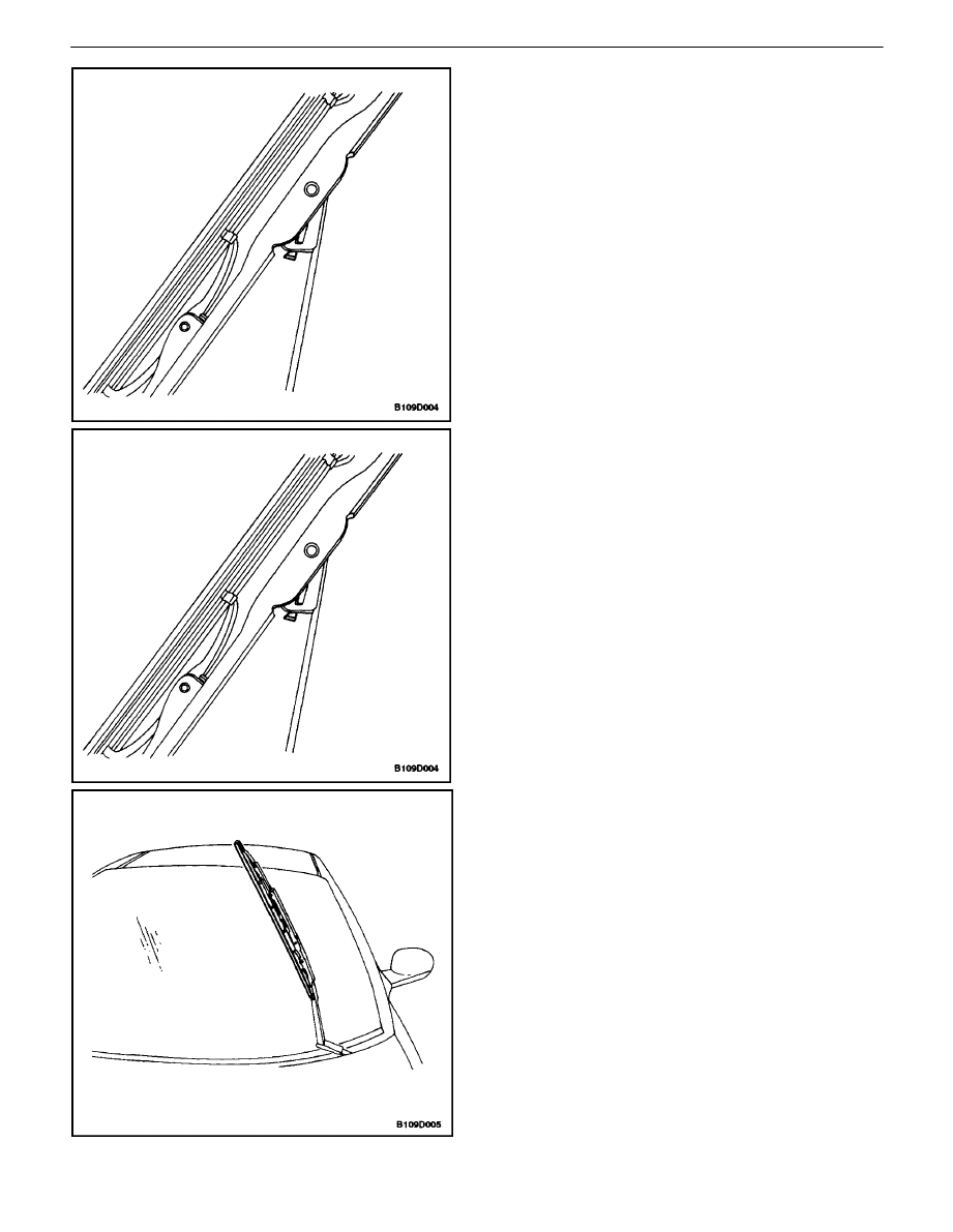
WINDSHIELD WIPER ARM
(Left–Hand Drive Shown, Right–Hand
Drive Similar)
Removal Procedure
1. Open the hood.
2. Remove the cap to reveal the wiper arm nut, if nec-
essary.
3. Remove the nut from the wiper arm.
4. Pull the wiper arm off.
Installation Procedure
1. Install the wiper arm.
Notice : Dissimilar metals in direct contact with each other
may corrode rapidly. Make sure to use the correct fasten-
ers to prevent premature corrosion.
2. Secure the wiper arm with the nut.
Tighten
Tighten the wiper arm nut to 11 N
S
m (97 lb–in).
3. Install the wiper arm nut cap, if necessary.
4. Close the hood.
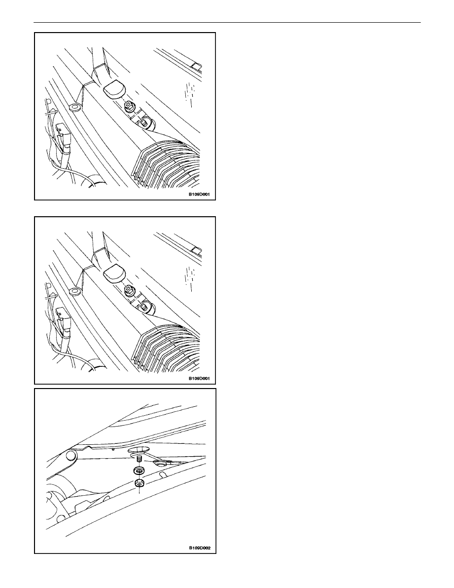
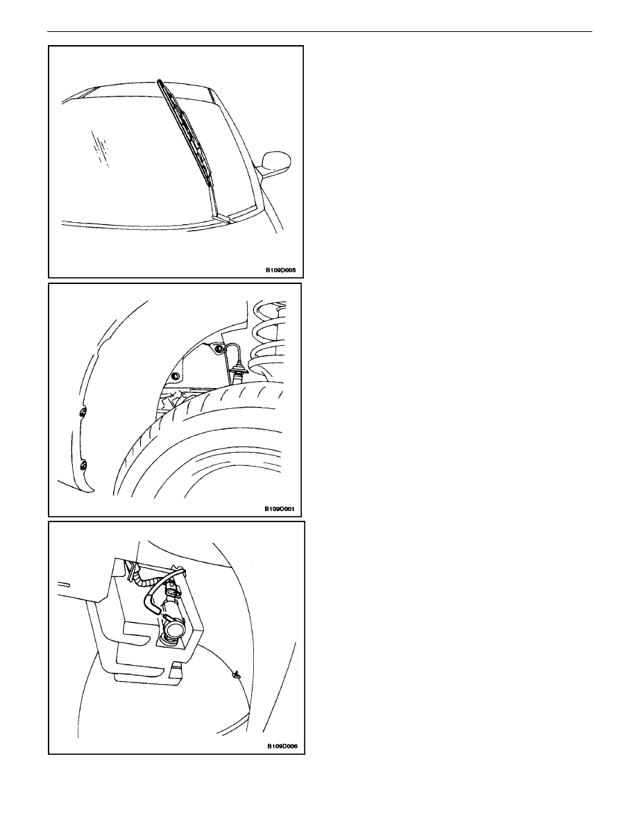
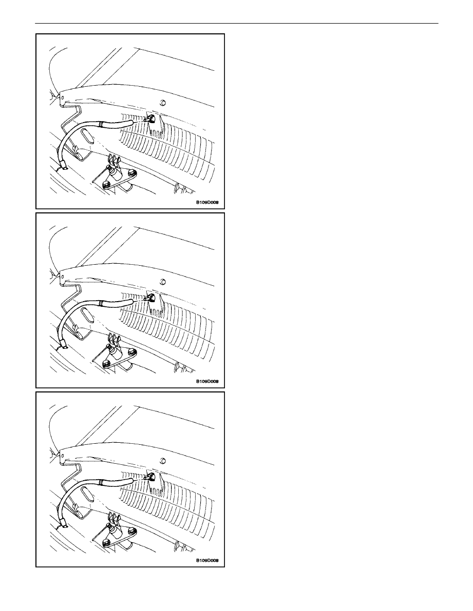
WINDSHIELD WIPER MOTOR
(Left–Hand Drive Shown, Right–Hand
Drive Similar)
Removal Procedure
1. Disconnect the negative battery cable.
2. Remove the left–side portion of the cowl vent grille.
Refer to Section 9R, Body Front End.
3. Remove the nut and the washer that secure the
wiper arm linkage to the motor drive shaft.
WIPERS/WASHER SYSTEMS 9D – 13
DAEWOO V–121 BL4
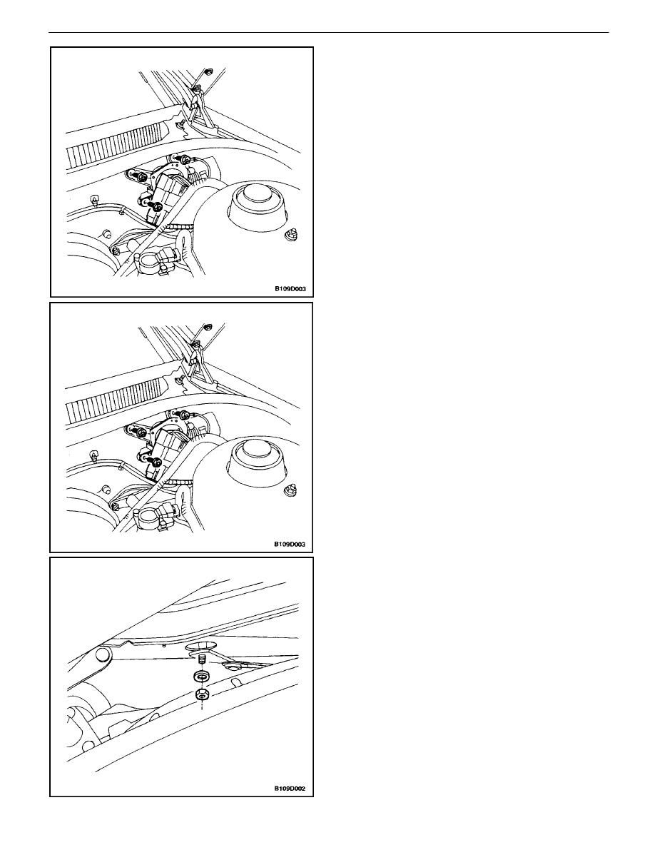
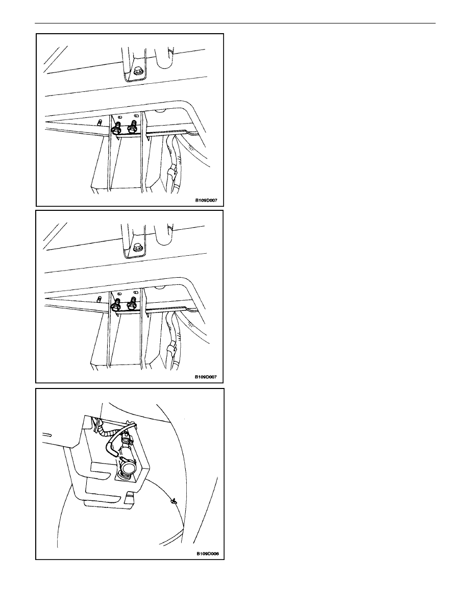
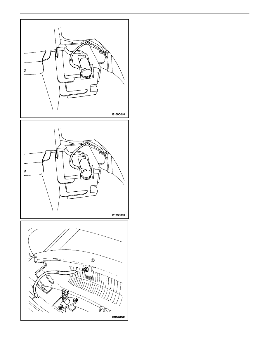
4. Pry the wiper arm linkage off the motor drive shaft.
5. Remove the nuts and reposition the engine coolant
reservoir.
6. Disconnect the electrical connector.
7. Remove the bolts and the wiper motor.
Installation Procedure
Notice : Dissimilar metals in direct contact with each other
may corrode rapidly. Make sure to use the correct fasten-
ers to prevent premature corrosion.
1. Install the wiper motor with the bolts.
Tighten
Tighten the wiper motor bolts to 8 N
S
m (71 lb–in).
2. Connect the electrical connector.
3. Press the wiper arm linkage onto the motor drive
shaft.
4. Install the wiper arm linkage to the motor drive shaft
with the washer and the nut.
Tighten
Tighten the wiper arm linkage nut to 5 N
S
m (44 lb–in).
5. Install the left side portion of the cowl vent grille.
Refer toSection 9R, Body Front End.
6. Connect the negative battery cable.
9D – 14
I
WIPERS/WASHER SYSTEMS
DAEWOO V–121 BL4
WINDSHIELD WIPER BLADE
(Typical)
Removal Procedure
1. Rotate the wiper blade on the arm.
2. While pressing the retainer clip, slide the wiper
blade down the wiper arm and remove the blade.
Installation Procedure
1. Install the wiper blade by sliding it onto the arm until
the retainer clip engages.
WINDSHIELD WIPER BLADE INSERT
(Front Shown, Rear Similar)
Removal Procedure
1. Slide the insert out of the wiper blade.
WIPERS/WASHER SYSTEMS 9D – 15
DAEWOO V–121 BL4
Installation Procedure
1. Slide the insert into the wiper blade.
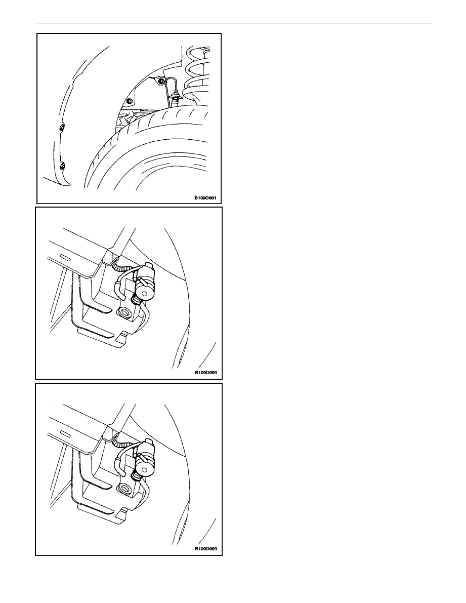
WINDSHIELD WASHER RESERVOIR
(Typical)
Removal Procedure
1. Disconnect the negative battery cable.
2. Remove the front left wheel. Refer to Section 2E,
Tires and Wheels.
3. Remove the bolts and the screws and the front
wheel well splash shield.
4. Disconnect the washer hose from the washer
pump.
5. Disconnect the reservoir pump electrical connector.
9D – 16
I
WIPERS/WASHER SYSTEMS
DAEWOO V–121 BL4
6. Remove the bolts and the reservoir.
Installation Procedure
Notice : Dissimilar metals in direct contact with each other
may corrode rapidly. Make sure to use the correct fasten-
ers to prevent premature corrosion.
1. Install the reservoir with the bolts.
Tighten
Tighten the washer fluid reservoir bolts to 8 N
S
m (71
lb–in).
2. Connect the reservoir pump electrical connector.
3. Connect the washer hose to the washer pump.
WIPERS/WASHER SYSTEMS 9D – 17
DAEWOO V–121 BL4
4. Install the front wheel well splash shield with the
bolts and the screws.
Tighten
Tighten the front wheel well splash shield bolts to 1.5
N
S
m (13 lb–in).
5. Install the front left wheel. Refer to Section 2E,
Tires and Wheels.
6. Connect the negative battery cable.
WINDSHIELD WASHER PUMP(S)
(Typical)
Removal Procedure
1. Disconnect the negative battery cable.
2. Remove the front left wheel. Refer to Section 2E,
Tires and Wheels.
3. Remove the bolts and the screws and the front
wheel well splash shield.
4. Disconnect the electrical connector.
5. Disconnect the washer hose from the washer
pump.
6. Remove the washer pump.
Installation Procedure
1. Install the washer pump.
2. Connect the washer hose to the washer pump.
3. Connect the electrical connector.
Notice : Dissimilar metals in direct contact with each other
may corrode rapidly. Make sure to use the correct fasten-
ers to prevent premature corrosion.
4. Install the front wheel well splash shield with the
bolts and the screws.
Tighten
Tighten the front wheel well splash shield bolts to 1.5
N
S
m (13 lb–in).
5. Install the front left wheel. Refer to Section 2E,
Tires and Wheels.
6. Connect the negative battery cable.
9D – 18
I
WIPERS/WASHER SYSTEMS
DAEWOO V–121 BL4
WINDSHIELD WASHER NOZZLES
Removal Procedure
1. Remove the cowl vent grille. Refer to Section 9R,
Body Front End.
2. Disconnect the washer hose from the nozzle.
3. Remove the nozzle from the cowl vent grille.
Installation Procedure
1. Install the nozzle onto the cowl vent grille.
2. Connect the washer hose to the nozzle.
3. Install the cowl vent grille. Refer to Section 9R,
Body Front End.
WINDSHIELD WASHER HOSES
(Typical)
Removal Procedure
1. Remove the cowl vent grille. Refer to Section 9R,
Body Front End.
2. Disconnect the windshield washer hose from the
washer nozzles.
WIPERS/WASHER SYSTEMS 9D – 19
DAEWOO V–121 BL4
3. Remove the front left wheel. Refer to Section 2E,
Tires and Wheels.
4. Remove the bolts and the screws and the front
wheel well splash shield.
5. Disconnect the washer hose from the washer reser-
voir.
6. Remove the washer hose.
Installation Procedure
1. Install the washer hose.
2. Connect the washer hose to the washer pump.
Notice : Dissimilar metals in direct contact with each other
may corrode rapidly. Make sure to use the correct fasten-
ers to prevent premature corrosion.
3. Install the front wheel well splash shield with the
bolts and the screws.
Tighten
Tighten the front wheel well splash shield bolts to 1.5
N
S
m (13 lb–in).
4. Remove the front left wheel. Refer to Section 2E,
Tires and Wheels.
5. Connect the windshield washer hose to the washer
nozzles.
6. Install the cowl vent grille. Refer to Section 9R,
Body Front End.
9D – 20
I
WIPERS/WASHER SYSTEMS
DAEWOO V–121 BL4
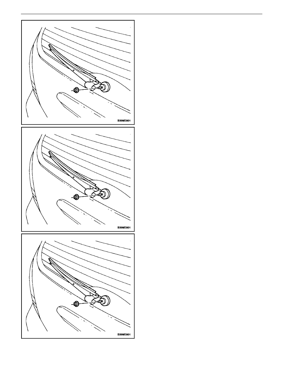
REAR WINDOW WIPER ARM
(Wagon Shown, Hatchback Similar)
Removal Procedure
1. Open the wiper arm access cap.
2. Remove the nut and the rear wiper arm.
Installation Procedure
Notice : Dissimilar metals in direct contact with each other
may corrode rapidly. Make sure to use the correct fasten-
ers to prevent premature corrosion.
1. Install the rear wiper arm with the nut.
Tighten
Tighten the wiper arm nut to 11 N
S
m (97 lb–in).
2. Close the wiper arm access cap.
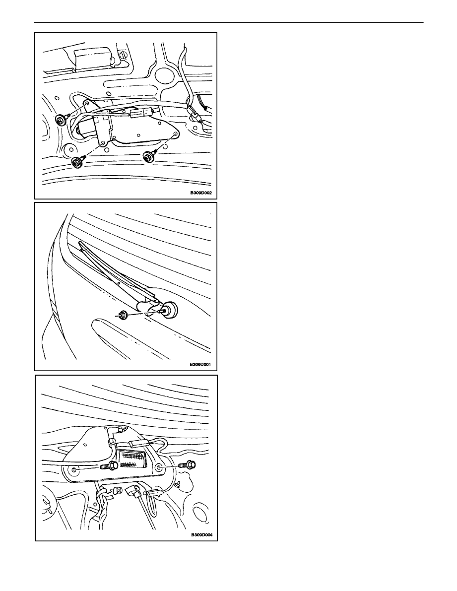
REAR WINDOW WIPER MOTOR
(HATCHBACK)
Removal Procedure
1. Disconnect the negative battery cable.
2. Remove the rear window wiper arm. Refer to ”Rear
Window Wiper Arm” in this section.
3. Remove the hatchback door lower garnish molding.
Refer to Section 9G, Interior Trim.
4. Remove the bolts and the rear wiper motor.
5. Disconnect the electrical connector.
WIPERS/WASHER SYSTEMS 9D – 21
DAEWOO V–121 BL4
Installation Procedure
1. Connect the electrical connector.
Notice : Dissimilar metals in direct contact with each other
may corrode rapidly. Make sure to use the correct fasten-
ers to prevent premature corrosion.
2. Install the rear wiper motor with the bolts.
Tighten
Tighten the wiper motor bolts to 8 N
S
m (71 lb–in).
3. Install the hatchback door lower garnish molding.
Refer toSection 9G, Interior Trim.
4. Install the rear window wiper arm. Refer to ”Rear
Window Wiper Arm” in this section.
5. Close the wiper arm access cap.
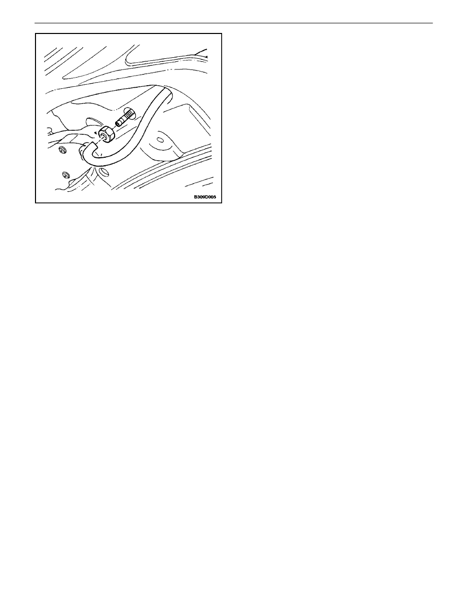
REAR WINDOW WIPER MOTOR
(WAGON)
Removal Procedure
1. Disconnect the negative battery cable.
2. Remove the rear window wiper arm. Refer to ”Rear
Window Wiper Arm” in this section.
3. Remove the wiper motor exterior retaining clip and
nut from the tailgate.
4. Remove the tailgate lower garnish molding.
5. Disconnect the electrical connector and the washer
hose.
6. Remove the bolts and the rear wiper motor.
9D – 22
I
WIPERS/WASHER SYSTEMS
DAEWOO V–121 BL4
Installation Procedure
Notice : Dissimilar metals in direct contact with each other
may corrode rapidly. Make sure to use the correct fasten-
ers to prevent premature corrosion.
1. Install the rear wiper motor with the bolts.
Tighten
Tighten the wiper motor bolts to 8 N
S
m (71 lb–in).
2. Connect the electrical connector and the washer
hose.
3. Install the tailgate lower garnish molding.
4. Install the wiper motor nut and exterior retaining clip
to the tailgate.
5. Install the rear window wiper arm. Refer to ”Rear
Window Wiper Arm” in this section.
6. Connect the negative battery cable.
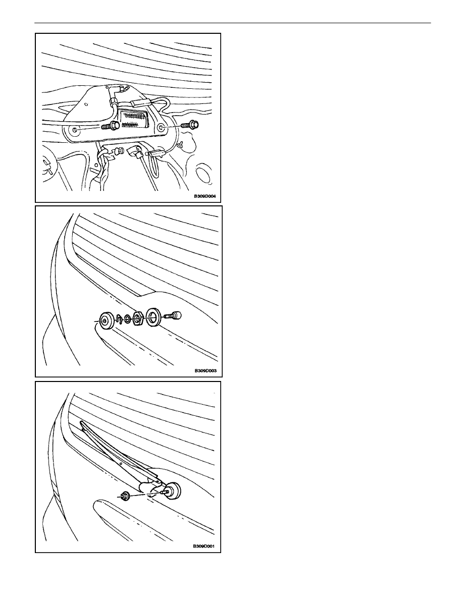
REAR WINDOW WASHER NOZZLE
(HATCHBACK)
Removal Procedure
1. Remove the hatchback door upper garnish molding.
Refer to Section 9G, Interior Trim.
2. Remove the washer hose from the nozzle.
3. Remove the nut and the washer nozzle.
WIPERS/WASHER SYSTEMS 9D – 23
DAEWOO V–121 BL4
Installation Procedure
1. Install the washer nozzle with the nut.
2. Install the washer hose to the nozzle.
3. Install the hatchback door upper garnish molding.
Refer toSection 9G, Interior Trim.

9D – 24
I
WIPERS/WASHER SYSTEMS
DAEWOO V–121 BL4
GENERAL DESCRIPTION
AND SYSTEM OPERATION
WINDSHIELD WIPER SYSTEM
The windshield wiper system consists of a wiper motor, a
linkage, a wiper arm and a blade, and a wiper/washer
switch. The windshield wiper circuit incorporates a self-
parking device which consists of a worm gear and a cam
plate in order to keep the circuit engaged temporarily when
the switch is turned off. The wiper system is driven by a
permanent magnet–type motor. The windshield wiper mo-
tor is mounted on the bulkhead and is directly connected
to the windshield wiper linkage.
The windshield wiper motor has two speeds, LO and HI,
and also has intermittent wiper capability. The wiper
switch is an integral part of the wiper/washer switch. Wind-
shield wiper operation is actuated through the lever on the
right side of the steering column.
WINDSHIELD WASHER SYSTEM
The windshield washer system is equipped with a washer
fluid reservoir, a washer fluid pump, hoses, nozzles, and
a wiper/washer switch. The windshield washer reservoir
is mounted behind the front left wheel well splash shield.
Attached to the reservoir is a washer pump, which pumps
fluid through the hoses to the two nozzles mounted on the
hood. The washer switch is an integral part of the wiper/
washer switch. Windshield washer operation is actuated
through the lever on the right side of the steering column.
REAR WINDOW WIPER/WASHER
SYSTEM
The rear window wiper system consists of a wiper motor,
a wiper arm, and a blade. The rear window wiper motor is
located inside the hatchback/tailgate door and is directly
connected to the rear window wiper. The rear window
washer system is equipped with a separate washer fluid
pump and hose. The hatchback has a hatch–mounted
rear window washer nozzle and on the wagon, the washer
nozzle is incorporated into the rear wiper motor. The rear
window washer reservoir is mounted behind the front left
wheel well splash shield. Attached to the reservoir is a
washer pump, which pumps fluid through a hose to the
rear washer nozzle.
Wyszukiwarka
Podobne podstrony:
76 WIPER WASHER SYSTEM
05 10 F01 Wiper Washer System
wiper washer system
WIPER WASHER SYSTEM
96ZJ 8K WIPER AND WASHER SYSTEMS
93ZJ Secc 8K Windshield Wiper and Washer Systems
M39d Wipers Washer Systems
BMW E38 schematic Wiper washers
Mądrzycki Osobowość jako system str 24 60, 174 211
8252 Windshield & headlamp wiper & washer inspection
wiper washer
66 Wiper and Washer
Analiza i pomiar systemów logistycznych wykład 1( 24.02.2008)(1), Logistyka, Logistyka
Gwne zaoenia systemu emerytur pomostowych Wyniki prac KT 24 09 08
Rola sektora ubezpieczeń w systemie finansowym kraju (24 str KI36ESQQQZ643ITJ2JGAYETI34PR4WQRUVW7Y4A
K. Popper - Społeczeństwo otwarte i jego wrogowie skrypt rozdz. 14-24, Studia, Współczesne systemy p
Historia filozofii nowożytnej, 24. Hegel - phanomenologie des geistes, system Hegla i „Fenomen
więcej podobnych podstron