Means Success In Electronic Servicing
Understanding How Color Video Cameras Work
Many consumers capture their
unforgettable moments with portable,
convenient camcorders, and business and
industry use video cameras for security,
process control, and remote monitoring.
Video camera and camcorder servicing is a
growing segment of video servicing that
offers great opportunity for servicers
trained and equipped in camera service.
Understanding how video cameras work is
the first step in servicing them effectively.
This Tech Tip explains the basic operation
of color video cameras, using a universal
functional block diagram.
Cameras and Camcorders
A video camera is a device that converts
visual images into electrical signals that
can be viewed, recorded, or broadcast.
Video cameras are found in two basic
configurations
-
as a stand-alone unit, or
as part of a camcorder.
As a stand-alone unit, a video camera’s
composite video output signal feeds an
external connector where it connects to
another stand-alone video device such as a
video recorder or monitor. Originally all
cameras were stand-alone units, but today
almost all consumer cameras are part of
the common camera/recorder/viewfinder
combination known as a camcorder
Stand-alone cameras are still widely used
by industry for monitoring and surveillance
applications, and for developing high
quality video signals in broadcast and
video production studios.
Camcorders are very popular witl
consumers because of their convenience
and small size, but broadcasters and video
production facilities also use camcorder!
Zoom/
Prevideo
A G C
G a m m a
Amp Correct Correct
From Sync Gen
Luma
Sync
Sync
Generator
Composite
Luma/
Video Out
Master
Chroma
Xtal
Mix
osc.
Burst
To EVF
Chrominance Process
Chroma
B-Y
Color AGC WB Gamma Color
MOD
Sep Amp
Correct Correct Matrix
Mix Fade Burst
R-Y
Adder
MOD
Fig. 1: Color video camera block diagram
FROM FOCUS
D R M
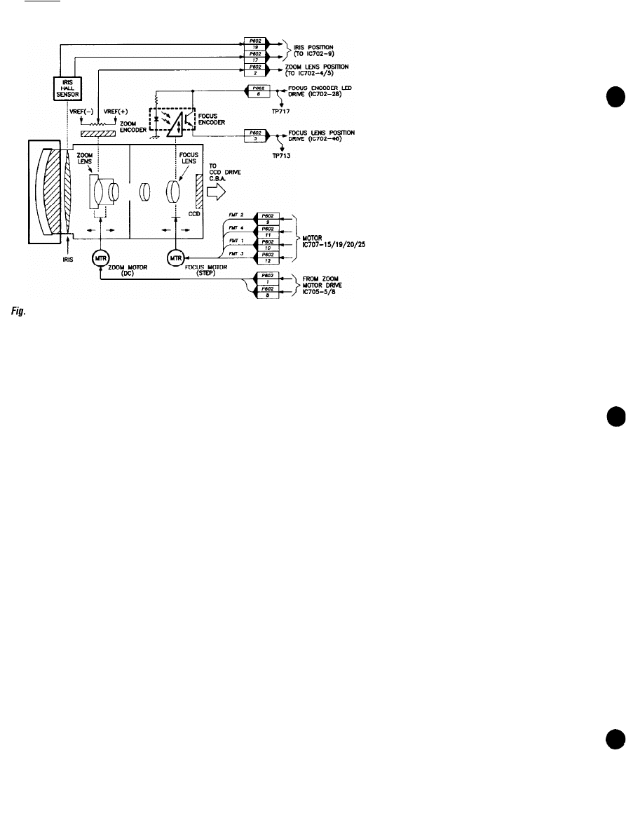
2: The iris controls the amount of light entering the lens assembly. The zoom lens provides a
variable focal length for viewing close-up images or magnifying far away images, while focus
maintains a well defined image. (Illustration courtesy of GE.)
extensively for field shots. Camcorders
combine a camera, a VCR, and a small
viewfinder to form a convenient unit for
recording and playing back video images.
Functionally there is little difference
between a stand-along camera and a
camera within a camcorder, except that the
camcorder camera shares some of its
support and control circuits (power supply,
system control, Y/C adder) with the VCR
section.
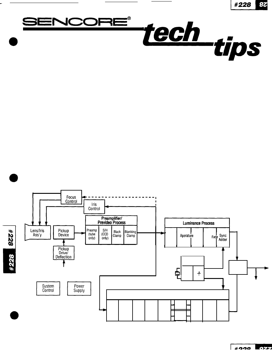
Universal Camera Functional
Block Diagram
The basic operation of all video cameras is
very similar. The Universal Video Camera
Block Diagram in Figure
1
shows the
interconnection and signal flow between
the major functional blocks. The order of
some blocks may vary slightly depending
on individual camera design and the type
of pickup device used. Following is a brief
description of the operation of each
functional block.
Lens/Iris Assembly
The lens assembly focuses light from the
scene onto the pick-up device’s light
sensitive surface. The auto-iris circuit
controls the amount of light passing
through the lens using a small motor to
open and close the iris diaphragm. Under
bright light conditions the auto-iris circuit
reduces the size of the iris opening so less
light strikes the pickup device.
Controlling the light striking the pickup
device controls the amplitude of the
prevideo signal, as explained in the next
section. The iris control circuit samples the
amplitude of the prevideo signal to obtain
feedback on the amount of light that is
striking the pick-up device.
The iris diaphragm is spring-loaded so it
automatically closes when power is
removed, or if the motor or iris control
circuit fails. Thus, a failure in the iris
control or iris drive circuit prevents light
from reaching the pick-up device and
results in no video output from the camera.
Auto-focus cameras have a small motor
inside the lens assembly to position the
internal lenses for proper focus. This focus
motor is part of the focus control circuit.
Focus control circuits either maximize the
high frequency information in the prevideo
signal, or respond to an infrared or LED
sensor.
Some cameras include an electronic zoom
control. The zoom control circuit operates
a motor that changes the lenses according
to input from the user operated control.
Sync Generator
The camera’s composite video output
signal contains luminance, sync, 3.58 MHz
subcarrier chrominance signals, and
chroma burst signals, which all must be
synchronized to each other. A master sync
oscillator, usually running at two or four
times the 3.58 MHz (3.579545 MHz) color
frequency, is divided down to produce
these synchronizing signals. The sync
generator provides horizontal and vertical
drive signals to the pick-up device,
composite sync and burst for the video
output, and 3.58 MHz subcarrier reference
signals for the R-Y and B-Y color
modulators.
Pick-up Device
The pickup device changes the visual
image into electrical signals. Three
different types of image pick-up devices
are used in video cameras; MOS, CCD, and
vacuum tube.
MOS and CCD pick-up devices
MOS (Metal Oxide Semiconductor) and
CCD (Charge Coupled Device) image pick-
up devices are solid state devices very
similar to each other in operation and
performance. Both consist of thousands of
photodiodes arranged into a matrix of
horizontal rows and vertical columns.
Each individual photodiode receives light
from a small area of the picture scene. This
causes it to produce a small electrical
charge proportional to the amount of light
striking its surface. Thus, the entire
photodiode matrix becomes an electrical
“picture” of the scene. The pick-up device
is scanned and the voltage levels (which
correspond to the brightness levels) at
small, individual points across the pick-up
surface are sampled. These small areas of
the picture sampled by each photodiode
are called picture elements or pixels.
By repeatedly scanning the photodiode
matrix, the individual electrical charges for
the whole picture are collected and
assembled. The scanning method used to
collect these charges is one major
difference between MOS and CCD pick-
ups.
MOS devices use a scanning method that
results in 4 output signals: white, yellow,
cyan, and green. (Older three-line MOS
devices didn’t have a green output signal).
One disadvantage of MOS devices is that
the output signals are low level (40-50
mV) and require low-noise preamps to
amplify the signals to a level usable by
standard signal processing circuits.
CCD devices have a single video output
line that contains all the luminance and
chrominance information needed to
generate NTSC composite video. The
output signal level is high enough so no
preamps are required. CCD devices have
proven to be more reliable than MOS
devices.
Although the output of a solid state pickup
device contains electrical information that
corresponds to the visual scene, the
output signal is not in analog NTSC format.
Instead, it is a digitally sampled signal
containing the charges from the individual
photodiodes or scene pixels. Signal
processing in the Prevideo Process block
converts this signal into an analog signal.
Tube pick-up devices
Tube pick-up devices are special CRTs that
use magnetic yoke deflection and a high
voltage supply to produce and scan an
electron beam across a light sensitive
surface or target. Each of the common
pick-up tubes; Vidicon, Saticon, and
Newvicons are similar in operation. The
output from a tube pick-up device is an
analog signal, similar to the NTSC
luminance signal.
Tube pick-ups have several major
disadvantages compared to solid state
pickups: 1) they are larger, more fragile,
and require heater and high voltage. 2)
Because they depend on a hot cathode
emission, they are subject to wearout. 3)
Pickup tubes require many scan correction
circuits to produce an acceptable output.
4) Their very low output level (200 µV or
less) requires extremely high-gain Iow-
noise preamplifiers. For these reasons,
tube pick-ups have been entirely replaced
by solid state CCD and MOS devices in
consumer cameras, and they are being
Prevideo
H. Sync
V. Sync
Horizontal Drive
From Sync
Generator
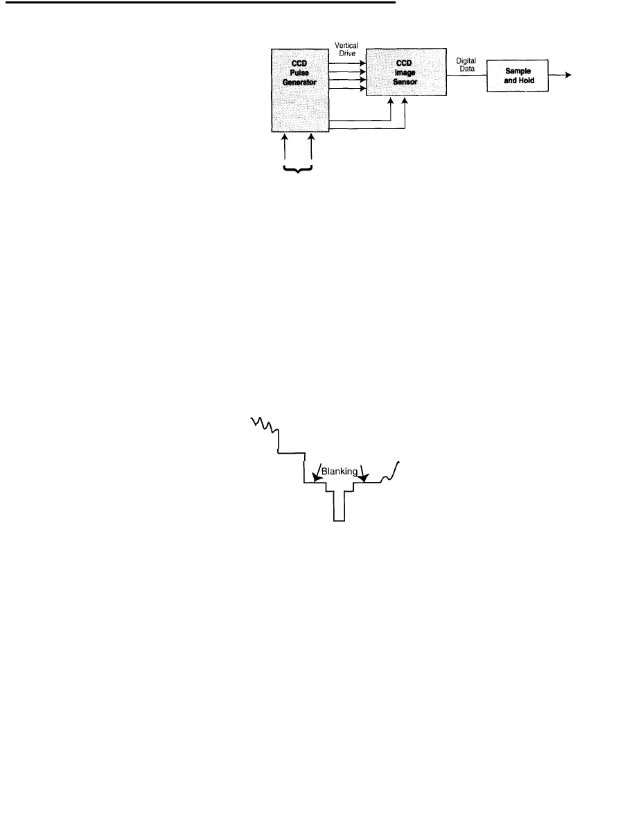
Fig.
3: A
CCD pickup is scanned using
4
vertical pulses and 2 horizontal pulses. The output of the
CCD is digital data fhat is converted to an analog signal.
phased out of most broadcast and
industrial camera applications.
Pick-up Drive/Deflection
Tube and solid state pick-up devices
require external signals to control their
raster scanning process. Tube pick-up
cameras use magnetic yoke deflection
(similar to television receivers) to move an
electron beam across the target surface.
Deflection circuits synchronized to the
B l a c k B l a c k
Black
Setup I
Fig. 4: The black clamp circuit sets the black
portion of the camera’s composite video
output signal and the blanking clamp circuit
fixes the level during blanking time.
master sync generator generate the
horizontal and vertical yoke currents.
In solid state pick-ups the horizontal rows
and vertical columns of photodiodes are
electronically selected to develop an output
signal. The drive pulses, provided by the
pick-up drive circuit, are synchronized to
the master sync generator.
Prevideo Process
The Prevideo Process section performs
several functions. First, preamplifiers
immediately following tube and MOS pick-
up devices increase the output to a level
that is useable by the following signal
processing circuits. This amplification is
important for maintaining an adequate
signal-to-noise ratio. CCD devices produce
a higher output and do not require a
preamplifier.
Solid-state pick-ups require an additional
signal processing stage. Unlike tube pick-
ups that produce an analog output, the
output of a solid-state pick-up is a digitally
sampled signal. Scanning the photodiodes
to collect the individual charges produces
an extra, high frequency carrier signal. A
sample and hold circuit, or a low pass
filter, removes this unwanted carrier and
passes only the low frequency information
that corresponds to the light level at each
pixel (analog luminance).
Following the sample and hold stage is a
black clamp. This stage is responsible for
establishing the black level of the
composite video output signal, as Figure 4
shows. The pick-up device scans an
optically black area of the pick-up surface
at the end of each horizontal scan line to
produce the black reference level.
The last Prevideo Process stage is the
blanking clamp. This circuit clamps the
entire blanking period to a fixed level with
respect to the previously established black
level. The difference between this blanking
level and the black reference level is called
black setup, as Figure 4 illustrates.
We call the output signal from the
Prevideo Process section “prevideo” since
it contains luminance picture information
plifiers
a level
signal
is
equate
a
ditional
the
digitally
gnal. A
pass
ier and
rmation
at each
is a
for
of the
4
ans an
surface
line to
is the
the
with
d black
called
the
since
and a color carrier signal. Yet the signal
still doesn’t contain the sync or color
burst reference signals that are part of a
composite video signal. Also, the color
carrier signal is in a form that can’t be
used by other standard NTSC video
devices without further chroma
processing.
Luminance Process
The Luminance Process circuits are fairly
simple since they process more
conventional luminance signals. The AGC
amp works with the iris control to
maintain a constant signal level. At low
light levels (when the iris is fully open) the
AGC adds amplification to maintain a
constant signal output. This circuit
normally amplifies only during low light
levels when the iris is already wide open
and cannot open any further to increase
the signal amplitude.
The aperture correction circuit,
sometimes called edge correction, is
responsible for reproducing sharp picture
detail. Ideally, the pickup device should
see very sharp edges in the scene, such
as the edge of a door. But, pickup devices
have a limit to the small size of picture
transitions and objects they can detect.
This limitation is due to the relatively large
size of the light sensitive area or
“aperture” of the individual photodiodes.
(In pickup tubes this size limit is due to
the size of the electron beam hitting the
target). The aperture correction circuit
senses the black to white picture
transitions (and vice versa) in both the
horizontal and vertical directions in the
picture scene. It then adds fast spikes to
the signal at these times to enhance the
signal transitions and sharpen the edges
of picture objects.
The gamma correction stage provides
additional gain for darker picture portions
of the camera’s video signal to correct for
the normal black compression that occurs
in all television and monitor CRTs.
Gamma correction allows the light levels
of the reproduced picture to match the
original picture scene exactly.
Many consumer cameras include a fade to
black feature. Pressing the fade button
tells the fade circuit to decrease the video
signal slowly to black, and to return from
black slowly to normal picture as the
button is released.
The last stage of the Luminance Process
section is the Sync Adder. The Snyc Adder
adds horizontal and vertical sync pulses
from the sync generator to the video
signal. The composite luminance and sync
(Y) output of the Luminance Process
section is sent to the Luma/Chroma
Mixer.
Chrominance Process
The chrominance process section
removes the color information from the
Prevideo signal and processes it into the
standard NTSC format that can be added
to the luminance signal.
The Color Separator separates the
chrominance from the rest of the prevideo
signal with a filter in tube cameras, and
with sample and hold circuit or signal
delay/summing circuit in MOS and CCD
cameras. The Color Separator output
signal has R-Y and B-Y signals, or
individual red, green, and blue signals,
depending on the camera design.
The chroma AGC amplifier
operates in step with the
luminance AGC. It amplifies
the color signal during low
light conditions when the iris is
wide open and unable to hold
the signal level constant.
White balance compensates
for differences in the color of
indoor and outdoor lighting.
The White Balance Correction
stage adjusts the level balance
between the red and blue color
signals to ensure that the
camera reproduces white when
it is pointed at white objects.
The auto white balance circuit
analyzes the color composition
of light arriving at the camera
by examining either the output
of the R-Y/B-Y separator
circuit, or an external white
balance sensor. After
averaging the color over a
period of time, it applies a
correction signal to either the
red or blue channel.
The Chrominance Processing section a
contains gamma correction circuitry.
with the luminance signal, the gamma
correction circuit adjusts the chroma
signal to correct for known C
compression.
The Color Matrix (R-Y/B-Y separatic
circuit separates the color signal into
and B-Y signals. These two signals
then modulated onto separate 3.58
subcarrier signals, with the R-Y
shifted 90 degrees from the E
subcarrier. These two
subcarriers add to produce
chrominance signal, which varies
amplitude according to color saturati
and varies in phase according to co
hue. After passing through a fade
similar to the luminance section
reference burst sample is added to
color signal during each horizon
blanking period.
Luma/Chroma Adder
After processing the luma and chro
signals, they are added in
Line Scanned
Black Level
Gray
53.5 Sec.
Sync
I I
I
Sec.
I
1
Horizontal Line
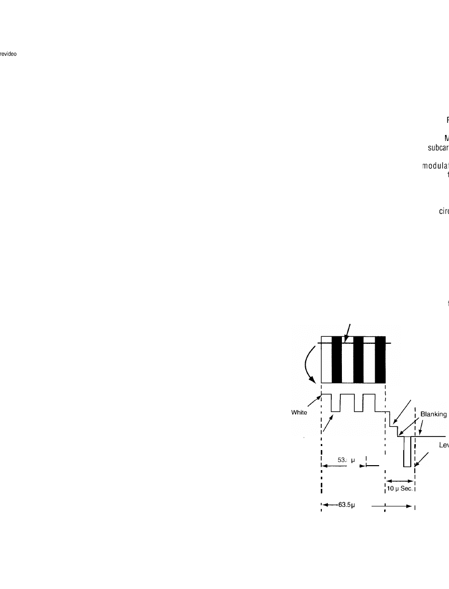
F~Q. 5: Scanning fhe pickup device produces signal level,
fhaf vary with fhe brightness /eve/s of fhe scene. The
camera adds black, blanking and sync pulses.
luma/chroma adder circuit to form the
NTSC composite video signal. The NTSC
composite video signal contains
luminance, vertical and horizontal sync,
color burst signals, and a 3.58 MHz
subcarrier reference signal. This signal
goes to the electronic viewfinder (EVF)
and to the camera’s video output jack. In a
camcorder the luma/chroma adder circuit
may be part of the VCR circuits.
The Composite Video Output
Signal
Now that we’ve covered the basic
operation of a video camera’s major
functional blocks, let’s take a closer look
at how everything comes together to
produce the composite video signal.
Signal Sampling
The pickup device converts the incoming
picture into many individual voltage
levels, with each voltage level
corresponding to the brightness level of
the picture at each photodiode. As the
pickup device is scanned, a continuous
sample of these individual voltage levels
forms an electrical representation of the
picture.
Horizontal Scan
The scanning of the pickup device starts
at the upper left corner of the scene, and
moves horizontally across the scene along
a thin line. The voltage samples along this
scan line are assembled into a continuous
video signal. The voltage changes in this
video signal correspond to the brightness
level changes in the scene along the scan
line.
As the scanning process reaches the right
edge of the pickup device, the camera
scans a black reference stripe and
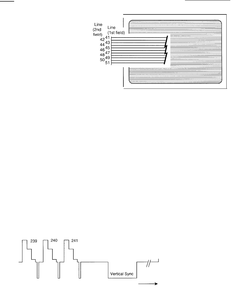
Fig. 7: The picture is scanned in two sets of lines. Each sef of scan lines is a field. The entire
picture (two fields) scan is a frame.
produces a blanked output. Scanning
from the left to the right side of the scene
takes about 53.5 microseconds. While the
output of the pickup device is blanked, the
camera adds a horizontal sync pulse and
readies itself to begin scanning from the
left side of the scene again.
After 1 horizontal line, which takes 63.5
microseconds (scan time + blanking time
+ sync time as Figure 5 shows), the scan
process starts all over. This time,
however, the horizontal line is shifted a bit
lower in the scene. Again, the scanning
process produces voltage samples
corresponding to the picture brightness
levels, plus blanking and sync pulses are
added to the signal after the scanning
process reaches the right edge of the
scene.
Vertical Scan
The scanning process continues down the
scene, with each horizontal scan line
occurring slightly lower than the previous
+ - V e r t i c a l B l a n k i n g
Fig. 6: The camera generates a vertical blanking pulse after line 241 that fasts for 21 lines.
line. The 241st horizontal scan line occurs
at the bottom of the scene. Upon its
completion, the camera generates a
blanking pulse and sync pulse that are
much longer than the pulses after the
preceeding horizontal lines. In fact, this
blanking pulse at the bottom of the scene
lasts for a period equal to 21 horizontal
scan lines, as illustrated in Figure 6. We
call these vertical blanking and vertical
sync pulses because they occur after the
entire scene is scanned vertically from top
to bottom. We also call them inactive
because they contain no picture
information.
After vertical blanking, the camera resets
its scanning process to the upper left
corner of the scene. Here the process
repeats with another 241 active horizontal
scan lines, plus vertical blanking and
sync. This complete set of 241 active
horizontal scan lines, plus vertical
blanking and sync pulses equal to another
21 lines (262 lines total) is known as one
vertical field. Each field, created by one
full scan from the top to the bottom of the
scene, occurs in approximately 1/60th of
a second.
Interlaced Scan
Although each field scans the entire scene
from top to bottom, two fields are used to
represent the complete scene. We call the
two fields “even” and “odd,” and together
they make up a “frame.” A frame includes
all the scan lines in one full picture. The
adjacent scan lines in each field are
spaced far enough apart so that another
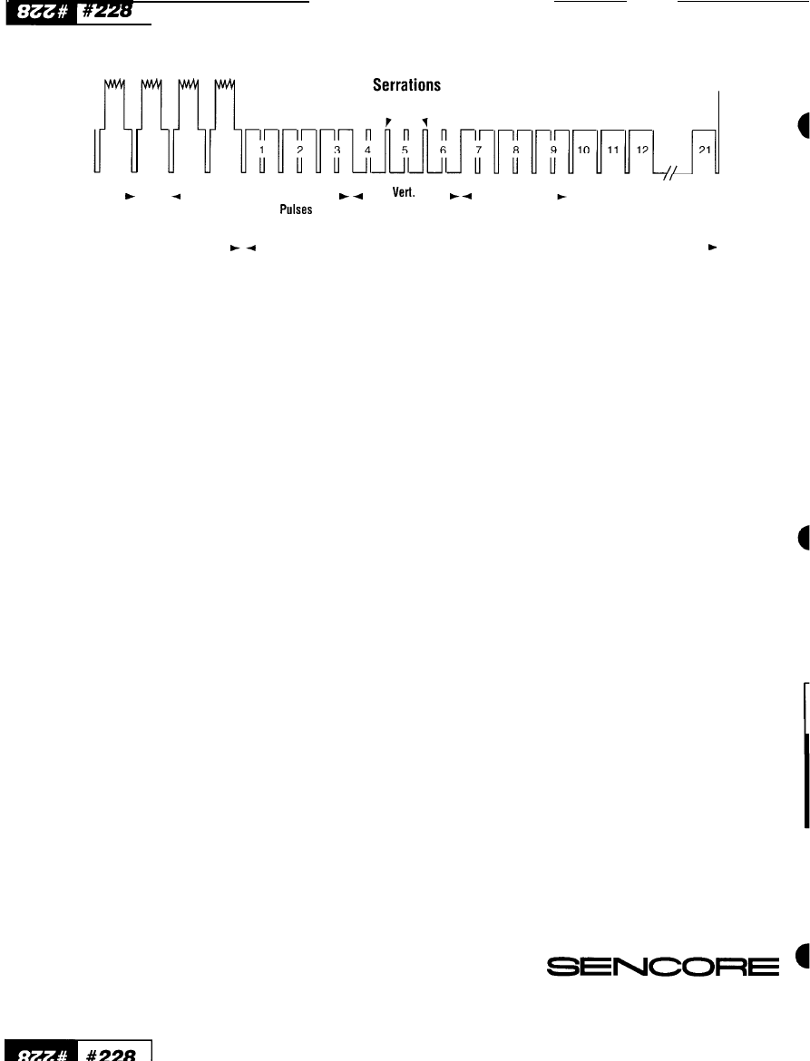
Video
One
Horizontal
Line
4 Equal.
Equal
Sync
Pulses
Bottom of
Picture
Vertical Blanking Interval
Fig.
8
Equalizing pulses and serrations during the vertical interval insure proper interlace scanning and maintain horizontal sync .
scan line will fit between them. In fact,
each line in the second field scans the
open spaces between the scan lines of the
first field, as illustrated in Figure 7. We call
this interlaced scan. Since one frame
requires two fields to complete, each frame
takes place in 2/60ths (1/30th) of a
second.
Why not just scan out the entire set of 482
scan lines in one pass, instead of scanning
it in two fields? If all the lines were
scanned sequentially, you would see flicker
in the television picture. The picture would
flicker because the bottom part of the
picture would be scanned 1/30th of a
second after the top part. After 1/30 of a
second the brightness of the CRT
phosphors at the top of the screen would
have dimmed enough that your eyes would
detect the drop in brightness. Another
solution would be to increase the scanning
speed so that all 482 lines would be
scanned in one pass within 1/60th of a
second. This won’t work however, because
the produced video bandwidth would
exceed the maximum allowed by the NTSC
system.
Instead, the camera scans the first field
(odd field) consisting of lines 1, 3, 5, etc.
in 1/60th of a second and the second field
(even field) scans lines 2, 4, 6, etc. in
another 1/60th of a second (Figure 7). With
this scan method the brightness in every
area of the recreated picture is refreshed
every 1/60th of a second. Since the human
eye cannot detect brightness variations
that occur this fast, the picture appears
continuous and flicker-free. Additionally,
the video bandwidth stays within the NTSC
limit of 4.2 MHz.
Due to the timing requirements of
interlaced scan, each field includes an
extra half horizontal scan line. The first
(even) field adds this extra half-line at the
end of the field, while the second (odd)
field adds the extra half-line at the
beginning of the field. That means that
each field contains 241.5 active scan lines,
plus vertical blanking and sync time equal
to another 21 scan lines, for a total of
262.5 scan lines per field. Each frame thus
includes 525 total horizontal scan lines.
video before vertical blanking and the even
field ends with a full line of video before
vertical blanking, the spacing of the
equalizing pulses and serrations is at half
horizontal line intervals, as Figure 8 shows.
Scan Frequencies
Each horizontal scan line, including
blanking and sync, takes approximately
63.56 microseconds. At this rate, 15,734
horizontal scan lines are completed every
second (one second divided by 63.56
microseconds). This makes the horizontal
scan frequency 15,734 Hz (or more exactly
15,734.26 Hz).
Because vertical blanking and sync last for
21 horizontal scan cycles after each
vertical field, a potential problem exits with
the scan oscillators in a television or
monitor. If the horizontal oscillator in a TV
or monitor was allowed to run for this long
without sync, the oscillator could drift off
frequency before it receives another
horizontal sync pulse. During interlaced
scan, some extra signals are added to the
vertical blanking and sync pulse interval to
prevent this problem (Figure 8).
Each vertical scan of the scene from top to
bottom, plus vertical blanking and sync,
takes about 1/60th of a second. Thus, 60
vertical scan cycles are completed every
second for a vertical scan frequency of 60
Hz (actually 59.94 Hz). This is also called
the vertical field rate. Since two fields make
up one complete one frame, 30 new
frames are completed every second,
meaning the vertical frame rate is 30 Hz
(actually 29.97 Hz).
These extra signals, which are substitute
horizontal sync pulses, are inserted during
the vertical blanking and sync periods, The
substitute horizontal sync pulses during
the vertical blanking interval are called
“equalizing pulses” and the pulses during
vertical sync time are called “serrations.”
For More Information,
Call Toll Free 1-800-SENCORE
l-800-736-2673
Since the odd field ends with a half line of
3200
Sencore Drive, Sioux Falls, SD 57017
Form # 5772
Printed in U.S.A.
Wyszukiwarka
Podobne podstrony:
Color Video Camera Operation
Color Video Camera Operation2
U disk camera (miniU8) Operating Instructions
Camera & Video
Przebieg porodu z video
The uA741 Operational Amplifier[1]
operatory i funkcje matematyczne
operator maszyn lesnych 833[02] o1 03 n
mechanik operator pojazdow i maszyn rolniczych 723[03] z2 04 n
Kierowca operator wózków jezdniowych 833401
mechanik operator pojazdow i maszyn rolniczych 723[03] o1 05 u
OPERAT STABLE VERSION ugoda id Nieznany
operator urzadzen przemyslu szklarskiego 813[02] z2 07 n
4 Steyr Operation and Maintenance Manual 8th edition Feb 08
operator urzadzen przemyslu spozywczego 827[01] z2 02 u
więcej podobnych podstron