
SECTION : 4D
FRONT DISC BRAKES
TABLE OF CONTENTS
SPECIFICATIONS
4D–1
. . . . . . . . . . . . . . . . . . . . . . . . . .
FASTENER TIGHTENING SPECIFICATIONS
4D–1
.
DIAGNOSIS
4D–1
. . . . . . . . . . . . . . . . . . . . . . . . . . . . . . . .
LINING INSPECTION
4D–1
. . . . . . . . . . . . . . . . . . . . . .
ROTOR INSPECTION
4D–1
. . . . . . . . . . . . . . . . . . . . .
MAINTENANCE AND REPAIR
4D–3
. . . . . . . . . . . . . . .
ON–VEHICLE SERVICE
4D–3
. . . . . . . . . . . . . . . . . . . . .
SHOE AND LINING
4D–3
. . . . . . . . . . . . . . . . . . . . . . . .
CALIPER
4D–4
. . . . . . . . . . . . . . . . . . . . . . . . . . . . . . . . .
ROTOR
4D–6
. . . . . . . . . . . . . . . . . . . . . . . . . . . . . . . . . .
SPLASH SHIELD
4D–7
. . . . . . . . . . . . . . . . . . . . . . . . . .
UNIT REPAIR
4D–9
. . . . . . . . . . . . . . . . . . . . . . . . . . . . . .
CALIPER OVERHAUL
4D–9
. . . . . . . . . . . . . . . . . . . . .
GENERAL DESCRIPTION AND SYSTEM
OPERATION
4D–11
. . . . . . . . . . . . . . . . . . . . . . . . . . . . .
DISC BRAKE CALIPER ASSEMBLY
4D–11
. . . . . . . .
SPECIFICATIONS
FASTENER TIGHTENING SPECIFICATIONS
Application
N
S
m
Lb–Ft
Lb–In
Brake Hose Inlet Fitting–to–Caliper Bolt
40
30
–
Caliper–to–Steering Knuckle Mounting Bolts
95
70
–
Retaining Frame–to–Caliper Housing Bolts
22–32
16–24
–
Rotor–to–Front Wheel Hub Detent Screw
4
–
35
Splash Shield–to–Steering Knuckle Screws
5
–
44
DIAGNOSIS
LINING INSPECTION
1. Raise and suitably support the vehicle.
2. Remove the front wheels. Refer toSection 2E, Tires
and Wheels.
3. Visually check the linings for minimum thickness
and wear.
4. Measure the thickness.
Important : The minimum thickness of the inner or outer
pad is 9 mm(0.35 inch).
1. Install the brake pads in axle sets only.
2. Install the front wheels. Refer toSection 2E, Tires
and Wheels.
3. Lower the vehicle.
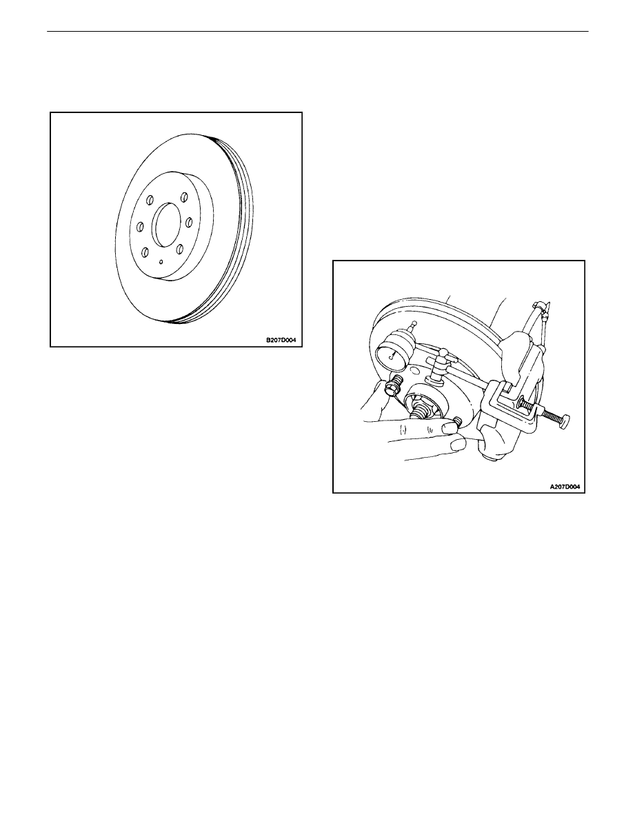
ROTOR INSPECTION
Thickness variation can be checked by measuring the
thickness of the rotor at four or more points around the cir-
cumference of the rotor. All measurements must be made
at the same distance in from the edge of the rotor.
A rotor that varies by more than 0.005 mm (0.0005 inch)
can cause pedal pulsations and/or front end vibration dur-
ing brake applications. A rotor that does not meet these
specifications should be refinished to specifications or re-
placed.
4D – 2
I
FRONT DISC BRAKES
DAEWOO V–121 BL4
During manufacturing, the brake rotor and the tolerances
of the braking surface regarding flatness, thickness varia-
tion, and lateral runout are held very close. The mainte-
nance of close tolerances on the shape of the braking sur-
faces is necessary to prevent brake roughness.
In addition to these tolerances, the surface finish must be
held to a specified range. The control of the braking sur-
face finish is necessary to avoid pulls and erratic perfor-
mance and to extend lining life.
Using a commercially available dial indicator, check lateral
runout as follows:
Notice : Permissible lateral runout is a maximum 0.03 mm
(0.0012 inch). If lateral runout exceeds the specification,
ensure that there is no dirt between the rotor and the hub
and that contact surfaces are smooth and free from burrs.
1. Position the transaxle in NEUTRAL.
2. Remove the rotor. Refer to ”Rotor” in this section.
3. Fasten the brake rotor to the wheel hub with two
wheel bolts.
4. Fasten a dial indicator to the brake caliper.
5. Set the gauge probe tip to approximately 10 mm
(0.39 inch) from the outer edge of the brake rotor,
perpendicular to the disc and under slight preload.
6. Remove the dial indicator and the wheel bolts con-
necting the rotor to the hub.
Important : Since accurate control of the rotor tolerances
is necessary for proper performance of the disc brakes, re-
finishing of the rotor should be done only with precision
equipment.
7.
If required, refinish the rotor with precision equip-
ment. Discard the rotor if it fails to meet the above
specifications after refinishing. Install the rotor. Re-
fer to ¡
³
Rotor¡
µ
in this section.
8.
Install the rotor. Refer to ”Rotor” in this section.
FRONT DISC BRAKES 4D – 3
DAEWOO V–121 BL4
MAINTENANCE AND REPAIR
ON–VEHICLE SERVICE
SHOE AND LINING
Removal Procedure
1. Raise and suitably support the vehicle.
2. To preserve wheel balance, mark the position of the
front wheel relative to the wheel hub. Remove the
front wheel. Refer to Section 2E, Tires and Wheels.
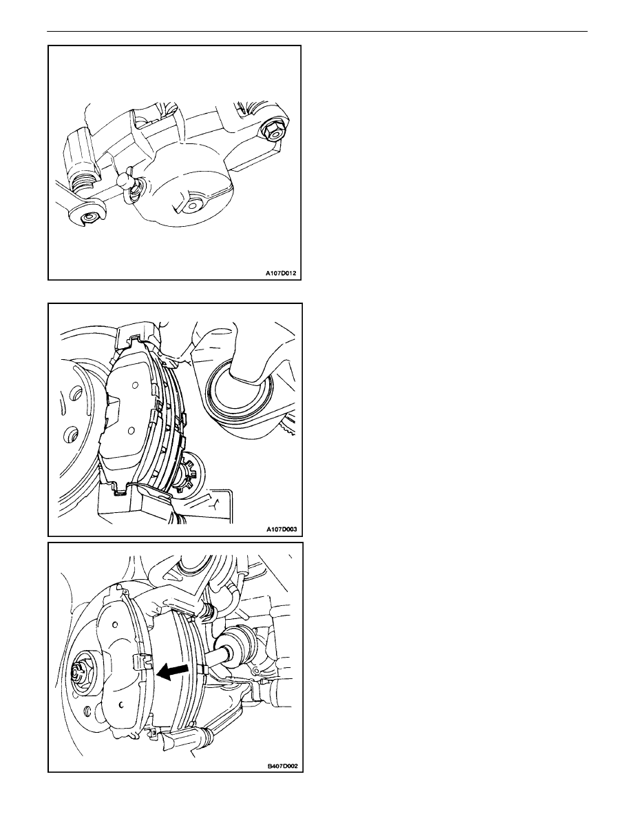
3. Remove the lower caliper mounting bolt.
Important : Caliper removal is not necessary to service
the brake shoes.
4. Pivot the caliper upward.
5. Remove the brake shoes.
4D – 4
I
FRONT DISC BRAKES
DAEWOO V–121 BL4
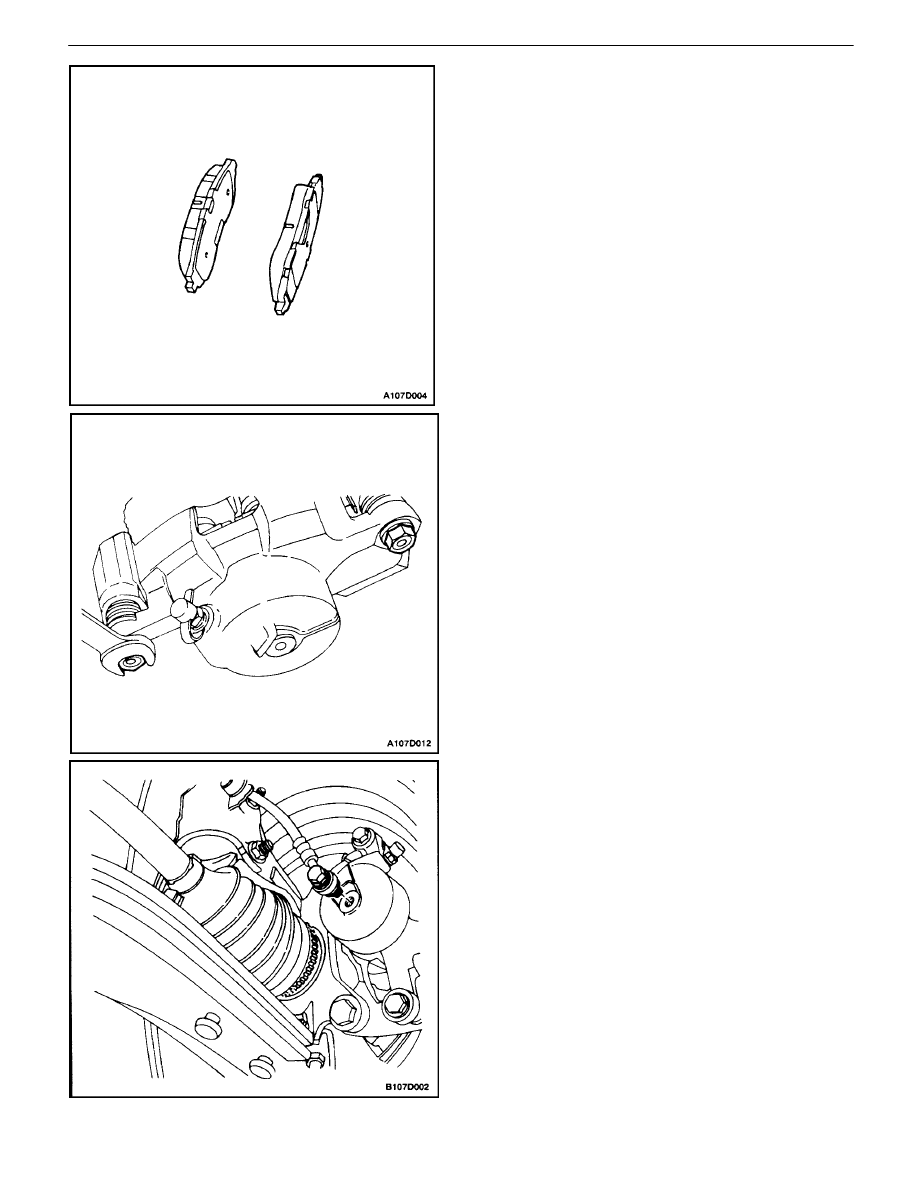
Installation Procedure
1. Install the brake shoes.
2. If new brake shoes are being installed, they will be
thicker than the worn pads that were removed.
Push the caliper piston inward, if necessary.
3. Pull the caliper downward and install the lower
mounting bolt.
Important : Do not damage the piston dust seal when the
caliper is pulled downward to reinstall the lowermounting
bolt.
Tighten
Tighten the caliper mounting bolt to 22–32 N
S
m
(16–24 lb–ft).
4. Align the marks that were made when removing the
front wheel, and install the wheel. Refer toSection
2E, Tires and Wheels.
5. Lower the vehicle.
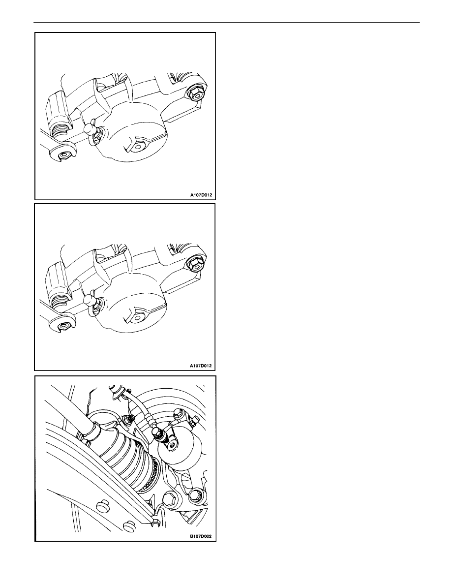
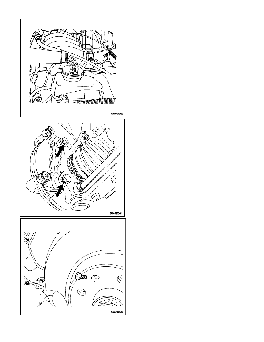
CALIPER
Removal Procedure
1. Raise and suitably support the vehicle.
2. To preserve wheel balance, mark the position of the
front wheel relative to the wheel hubs. Remove the
wheel. Refer toSection 2E, Tires and Wheels.
3. Remove the bolt which attaches the brake hose to
the caliper. Remove the washers.
FRONT DISC BRAKES 4D – 5
DAEWOO V–121 BL4
4. Plug the openings at the caliper inlet and the brake
hose to prevent fluid loss or contamination.
5. Remove the caliper mounting bolts.
6. Remove the caliper.
Installation Procedure
1. Install the caliper
2. Install the caliper mounting bolts.
Tighten
Tighten the caliper mounting bolts to 22–32 N
S
m
(16–24 lb–ft).
3. Connect the caliper inlet hose with the bolt and the
washers.
Tighten
Tighten the brake hose–to–caliper bolt to 40 N
S
m (30
lb–ft).
4D – 6
I
FRONT DISC BRAKES
DAEWOO V–121 BL4
4. Align the marks that were made when removing the
front wheel, and install the wheel. Refer toSection
2E, Tires and Wheels.
5. Lower the vehicle.
6. Fill the master cylinder reservoir to the proper level
with clean brake fluid.
7. Bleed the air out of the brake system. Refer toSec-
tion 4A, Hydraulic BrakesorSec–tion 4F, Antilock
Brake System.
8. Recheck the fluid level in the master cylinder.
9. Repeatedly press the brake pedal to bring the pads
into contact with the rotor. Do not move the vehicle
until a firm pedal is obtained.
ROTOR
Removal Procedure
1. Remove the caliper. Refer to ”Caliper”in this sec-
tion.
2. Remove the brake pads.
3. Remove the caliper mounting bracket.
4. Remove the rotor detent screw.
5. Remove the rotor.

FRONT DISC BRAKES 4D – 7
DAEWOO V–121 BL4
Installation Procedure
Important : To guarantee uniform braking, always refinish
both rotors even if only one rotor is defective. If a rotor is
being replaced, use a new rotor on both sides of the ve-
hicle.
1. Install the rotor on the front wheel hub and install
the detent screw.
Tighten
Tighten the rotor detent screw to 4 N
S
m (35 lb–in).
2. Apply a few drops of thread–locking compound to
the bolts and install the caliper bracket.
Tighten
Tighten the caliper bracket–to–steering knuckle
mounting bolts to 95 N
S
m (70 lb–ft).
3. Install the brake pads and the caliper. See”Caliper”
in this section.
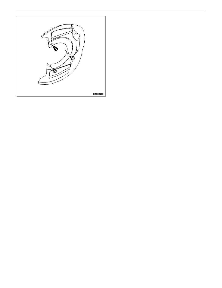
SPLASH SHIELD
Removal Procedure
1. Remove the rotor. Refer to ”Rotor” in this section.
2. Remove the screws for the splash shield from the
steering knuckle.
3. Remove the splash shield.
4D – 8
I
FRONT DISC BRAKES
DAEWOO V–121 BL4
Installation Procedure
1. Install the splash shield.
2. Secure the splash shield to the steering knuckle
with the screws.
Tighten
Tighten the splash shield screws to 5 N
S
m (44 lb–in).
3. Install the rotor. Refer to ”Rotor” in this section.
FRONT DISC BRAKES 4D – 9
DAEWOO V–121 BL4
UNIT REPAIR
CALIPER OVERHAUL
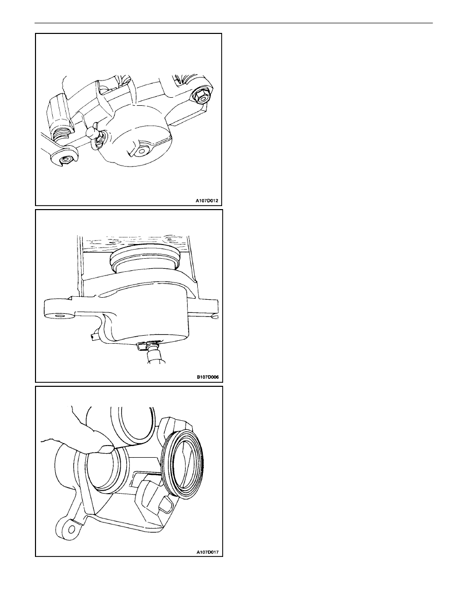
Disassembly Procedure
1. Remove the caliper. Refer to ”Caliper” in this sec-
tion.
CAUTION : Do not attempt to catch the piston when
attempting to remove the piston with compressed air.
The piston will pop out of its bore with enough force
to damage a hand or fingers.
Important : When removing the caliper piston with com-
pressed air, insert a piece of hardwood into the caliper to
prevent damage to the piston.
2. Apply unlubricated compressed air at the hose inlet
of the caliper.
3. Remove the piston from its bore, and remove the
piston dust seal.
4D – 10
I
FRONT DISC BRAKES
DAEWOO V–121 BL4
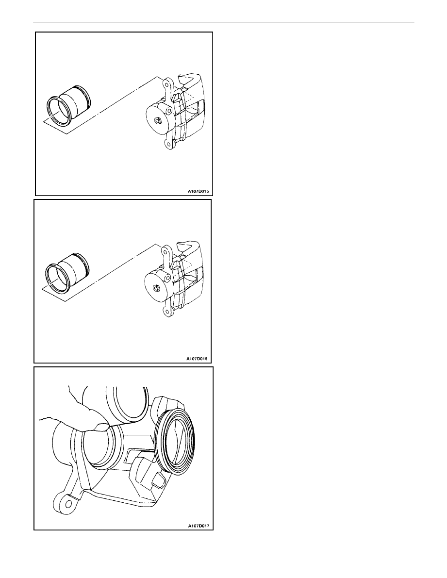
4. Remove the inner seal from the bore.
5. Remove the bleeder valve protector and the bleed-
er valve.
Assembly Procedure
1. Clean all parts in denatured alcohol or brake fluid.
Dry the parts with unlubricated compressed air and
blow out all passages in the housing and bleeder
valve.
2. Inspect the piston and caliper for scoring, nicks, or
corrosion. Replace any components which show
these conditions.
3. Install the caliper bleeder valve.
Important : Do not use a hone or any other procedure to
remove material from the caliper bore or piston.
4. Lubricate a new piston inner seal with brake fluid.
5. Install the piston inner seal into the groove in the
caliper bore.
6. Install the piston dust seal in its groove.
7. Lubricate the piston with brake fluid.
8. Push the piston inward until it is properly seated.
Make sure that the dust seal is in the correct
groove in the piston and caliper.
9. Reinstall the caliper. Refer to”Caliper”in this section.
10. Bleed the brake system. Refer toSection 4A, Hy-
draulic brakesor Section 4F, Antilock Brakes, if ap-
plicable.

FRONT DISC BRAKES 4D – 11
DAEWOO V–121 BL4
GENERAL DESCRIPTION
AND SYSTEM OPERATION
DISC BRAKE CALIPER ASSEMBLY
This caliper has a single bore and is mounted to the steer-
ing knuckle with two mounting bolts. Hydraulic pressure,
created by pressing the brake pedal, is converted by the
caliper to a stopping force. This force acts equally against
the piston and the bottom of the caliper bore. It moves the
piston outward and slides the caliper inward, resulting in
a clamping action on the rotor. This clamping action forces
the linings against the rotor, creating friction to stop the ve-
hicle.
S
Replace all components included in the repair kits
used to service the caliper.
S
Lubricate the rubber parts with clean brake fluid to
ease assembly.
S
Do not use lubricated shop air on brake parts, as
damage to the rubber components may result.
S
If any hydraulic component is removed or discon-
nected, it may be necessary to bleed all or part of
the brake system.
S
Replace the pads in axle sets only.
S
The torque values specified are for dry, unlubri-
cated fasteners.
S
Perform the service operations on a clean bench,
free from all mineral oil materials.
Wyszukiwarka
Podobne podstrony:
M34d Front Disc Brakes
REAR DISK BRAKES 4E 18
11 drive shaft and front axle
11 Front Wheel Suspension Steering
lab 9 11 4d
Brakes Front Brakes Replacement
11 Front Wheel Suspension Steering
Zarz[1] finan przeds 11 analiza wskaz
11 Siłowniki
11 BIOCHEMIA horyzontalny transfer genów
PKM NOWY W T II 11
wyklad 11
R1 11
więcej podobnych podstron