
SECTION : 4E
REAR DISC BRAKES
CAUTION : Disconnect the negative battery cable before removing or installing any electrical unit or when a tool
or equipment could easily come in contact with exposed electrical terminals. Disconnecting thes cable will help
prevent personal injury and damage to the vehicle. The ignition must also be in LOCK unless otherwise noted.
TABLE OF CONTENTS
SPECIFICATIONS
4E–1
. . . . . . . . . . . . . . . . . . . . . . . . . .
FASTENER TIGHTENING SPECIFICATIONS
4E–1
.
DIAGNOSIS
4E–2
. . . . . . . . . . . . . . . . . . . . . . . . . . . . . . . .
LINING INSPECTION
4E–2
. . . . . . . . . . . . . . . . . . . . . .
ROTOR INSPECTION
4E–2
. . . . . . . . . . . . . . . . . . . . .
MAINTENANCE AND REPAIR
4E–3
. . . . . . . . . . . . . . .
ON–VEHICLE SERVICE
4E–3
. . . . . . . . . . . . . . . . . . . . .
SHOE AND LINING
4E–3
. . . . . . . . . . . . . . . . . . . . . . . .
CALIPER
4E–4
. . . . . . . . . . . . . . . . . . . . . . . . . . . . . . . . .
ROTOR
4E–6
. . . . . . . . . . . . . . . . . . . . . . . . . . . . . . . . . .
SPLASH SHIELD/BACKPLATE AND PARKING
BRAKE LEVER
4E–7
. . . . . . . . . . . . . . . . . . . . . . . . . .
UNIT REPAIR
4E–15
. . . . . . . . . . . . . . . . . . . . . . . . . . . . .
CALIPER OVERHAUL
4E–15
. . . . . . . . . . . . . . . . . . . .
GENERAL DESCRIPTION AND SYSTEM
OPERATION
4E–18
. . . . . . . . . . . . . . . . . . . . . . . . . . . . .
DISC BRAKE CALIPER
4E–18
. . . . . . . . . . . . . . . . . . .
SPECIFICATIONS
FASTENER TIGHTENING SPECIFICATIONS
Application
N
S
m
Lb–Ft
Lb–In
Bleeder Valve
11
–
97
Brake Hose Caliper Inlet Bolt
32
24
–
Caliper Bracket Mounting Bolts
56
41
–
Caliper Mounting Bolts
31
23
–
Parking Brake Shoe Hold–Down Spring As-
sembly Screw
3.5
–
31
Rotor Detent Screw
4
–
35
Splash Shield Bolts
25
18
–
Wheel Hub Assembly–to–Spindle Shaft
Castle Nut
25 + 1*
18 + 0.7
–
* Tighten the castle nut up to 1 N
S
m (9 lb–in) as needed to align the castle nut cotter pin notch with the spindle shaft hole.
4E – 2
I
REAR DISC BRAKES
DAEWOO V–121 BL4
DIAGNOSIS
LINING INSPECTION
1. Raise and suitably support the vehicle.
2. Remove the rear wheels. Refer toSection 2E, Tires
and Wheels.
3. Visually check the linings for minimum thickness
and wear.
4. Measure the thickness.
Important : The minimum thickness of the lining is 0.2 mm
(0.08 inch).
5.
Install the shoe and linings in axle sets only.
6.
Install the rear wheels. Refer toSection 2E, Tires
and Wheels.
7.
Lower the vehicle.
ROTOR INSPECTION
Brake rotors are manufactured with close tolerances for
thickness variation, flatness, and lateral runout. However,
pits and grooves are created in the rotors during usage.
The lack of uniformity of the braking surfaces of the rotor
can cause inadequate braking and a pulsating pedal dur-
ing braking. The surface finish of the rotor is also important
because an unsuitable surface finish can cause pulling
and rapid wear of the brake shoe lining.
If a rotor does not meet specifications, it should be refin-
ished to specification or replaced. Refinishing of the rotor
should only be done with precision equipment.
Thickness variation can be checked by measuring the
thickness of the rotor at four or more points around the cir-
cumference of the rotor. All measurements must be made
at the same distance from the edge of the rotor. A rotor that
varies by more than 0.10 mm (0.004 inches) can cause
pedal pulsations and/or front end vibration during braking.
Thickness can be measured with a commercially available
micrometer.
Light scoring of the rotor surfaces is acceptable if it does
not exceed 0.40 mm (0.016 inches) in depth. Scoring mea-
surements can be made with a commercially available
brake micrometer.
Lateral runout cannot exceed 0.10 mm (0.004 inches). If
lateral runout exceeds the specification, make sure there
is no dirt between the rotor and the hub and that hub–to–
rotor contact surfaces are smooth and free from burrs.
Use a commercially available dial indicator to check the
lateral runout according to the following procedure:
1. Position the transaxle in NEUTRAL and raise the
vehicle.
2. To preserve wheel balance, mark the relative posi-
tions of the wheel and the hub, and remove the
front wheel.
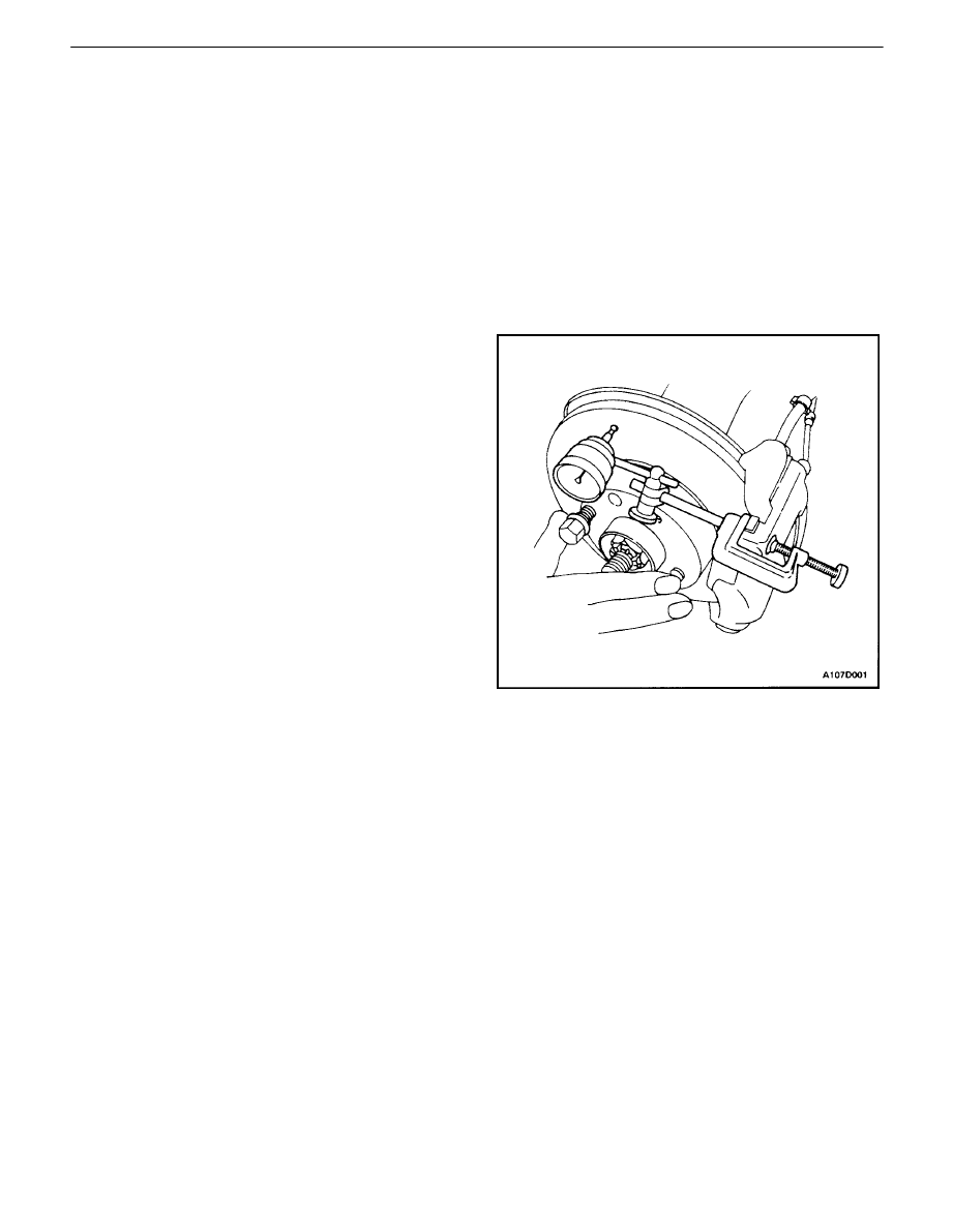
3. Fasten the brake rotor to the wheel hub with two
wheel bolts.
4. Fasten a dial indicator to the brake caliper.
5. Place the gauge tip approximately 234 mm (9.2
inches) from the center of the rotor hole, perpendic-
ular to the disc and under slight preload. Observe
the gauge while rotating the rotor.
6. After the measuring is completed, remove the dial
indicator and wheel bolts.
7. If necessary, refinish the rotor with precision equip-
ment. Measure the runout again after refinishing. If
the runout exceeds 0.10 mm (0.004 inches) after
refinishing, the rotor should be replaced.
8. Align the marks that weremade before the wheel
was removed and install the front wheel.
9. Lower the vehicle.
REAR DISC BRAKES 4E – 3
DAEWOO V–121 BL4
MAINTENANCE AND REPAIR
ON–VEHICLE SERVICE
SHOE AND LINING
Removal Procedure
1. Raise and suitably support the vehicle.
2. To preserve wheel balance, mark the position of the
rear wheels relative to the wheel hubs and remove
the wheels. Refer toSection 2E, Tires and Wheels.
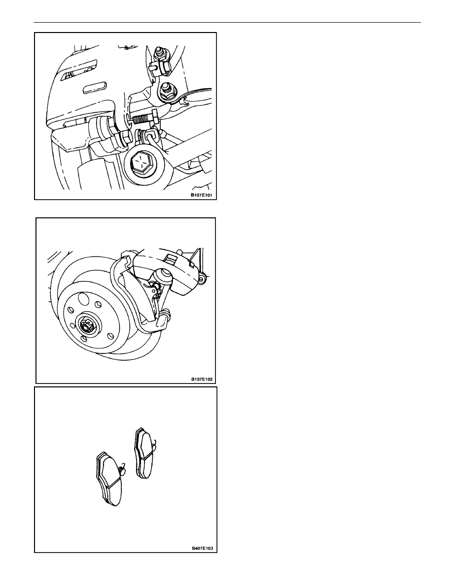
3. Remove the lower caliper mounting bolt.
Important : It is not necessary to remove the caliper to
service the brake shoes.
4. Pivot the caliper upward.
5. Remove the brake shoes.

4E – 4
I
REAR DISC BRAKES
DAEWOO V–121 BL4
Installation Procedure
1. Measure the minimum shoe lining thickness. Refer
to”Lining Inspection”in this section.
2. Install the brake shoes.
3. Push the piston inward, if needed.
Notice : Do not damage the piston seal when the caliper
is pivoted downward.
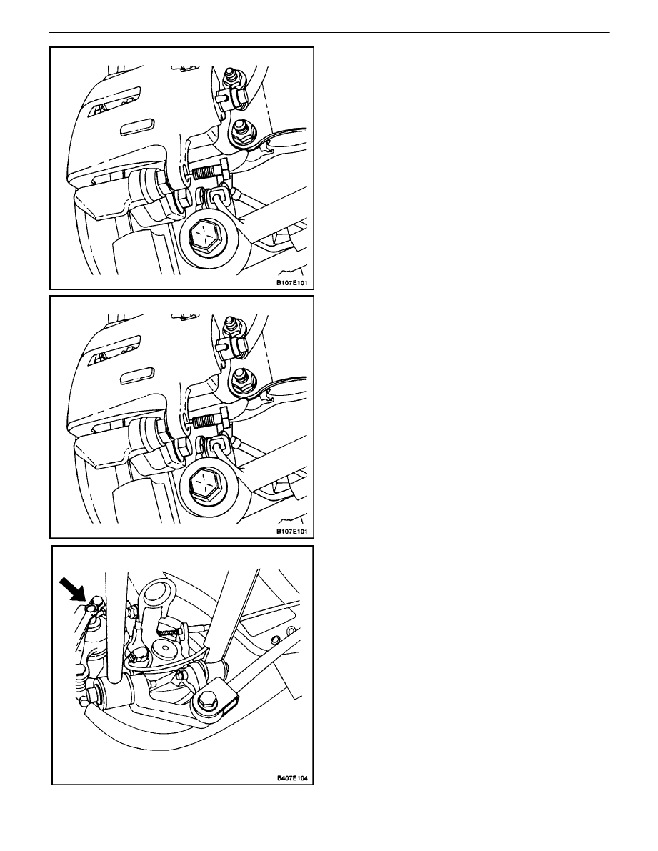
4. Pivot the caliper downward and install the lower
bolt.
Tighten
Tighten the lower caliper mounting bolt to 31 N
S
m (23
lb–ft).
5. Align the match marks that were made before re-
moval and install the rear wheels. Refer toSection
2E, Tires and Wheels.
6. Lower the vehicle.
CALIPER
Removal Procedure
1. Raise and suitably support the vehicle.
2. To preserve wheel balance, mark the position of the
rear wheels relative to the wheel hubs and remove
the wheels. Refer toSection 2E, Tires and Wheels.
3. Remove the brake hose caliper inlet bolt and the
washers.
REAR DISC BRAKES 4E – 5
DAEWOO V–121 BL4
4. Plug the openings in the caliper and the brake hose
to prevent fluid loss and contamination.
5. Remove the caliper mounting bolts and the caliper.
Installation Procedure
1. Install the caliper with the mounting bolts.
Tighten
Tighten the caliper mounting bolts to 31 N
S
m (23 lbft).
2. Connect the brake hose and the washers with the
mounting bolt.
Tighten
Tighten the brake hose caliper inlet bolt to 32 N
S
m (24
lb–ft).
4E – 6
I
REAR DISC BRAKES
DAEWOO V–121 BL4
3. Align the match marks that were made before re-
moval and install the rear wheels. Refer toSection
2E, Tires and Wheels.
4. Fill the master cylinder to the proper level with
clean brake fluid.
5. Bleed the caliper. Refer toSection 4A, Hydraulic
Brakes.or Section 4F, Antilock Brakes,if applicable.
6. Recheck the fluid level.
7. Repeatedly press the brake pedal to bring the pads
into contact with the rotor. Do not move the vehicle
until a firm pedal is obtained.
ROTOR
Removal Procedure
1. Raise and suitably support the vehicle.
2. To preserve wheel balance, mark the position of the
rear wheels relative to the wheel hubs and remove
the wheels. Refer toSection 2E, Tires and Wheels.
Notice : To prevent damage to the brake hose, do not
hang the caliper from the brake hose.
3. Remove the caliper. Refer to”Caliper”in this section.
4. Remove the caliper bracket.
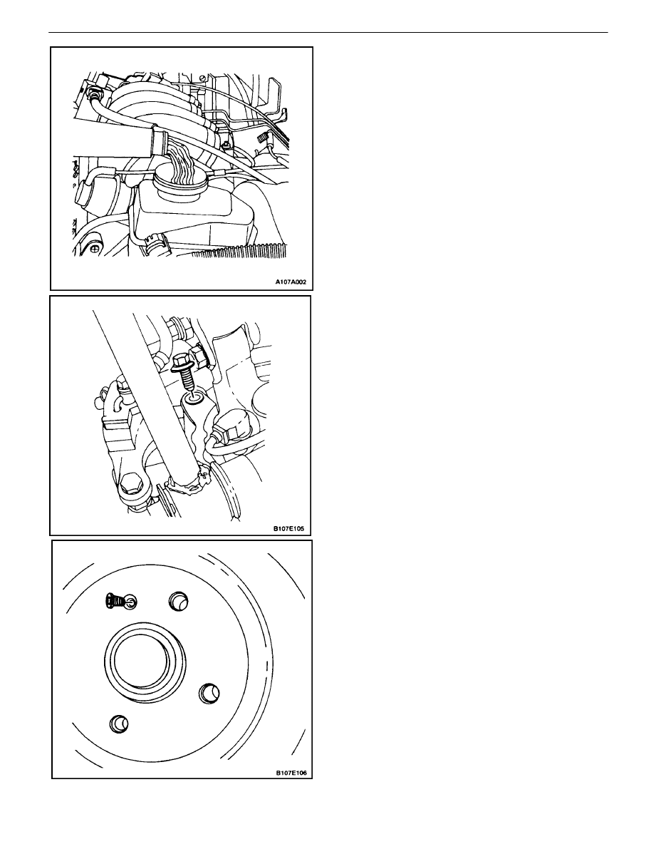
5. Remove the rotor detent screw.
6. Remove the rotor.
REAR DISC BRAKES 4E – 7
DAEWOO V–121 BL4
Installation Procedure
1. Inspect the rotor. Refer to”Rotor Inspection”in this
section.
2. Install the rotor with the detent screw.
Tighten
Tighten the rotor detent screw to 4 N
S
m (35 lb–in).
3. Install the caliper bracket.
Tighten
Tighten the caliper bracket mounting bolts to 56 N
S
m
(41 lb–ft).
4. Install the caliper. Refer to”Caliper”in this section.
5. Align the match marks that were made before re-
moval, and install the rear wheels. Refer toSection
2E, Tires and Wheels.
6. Lower the vehicle.
SPLASH SHIELD/BACKPLATE AND
PARKING BRAKE LEVER
Removal Procedure
1. Remove the rotor. Refer to”Rotor”in this section.
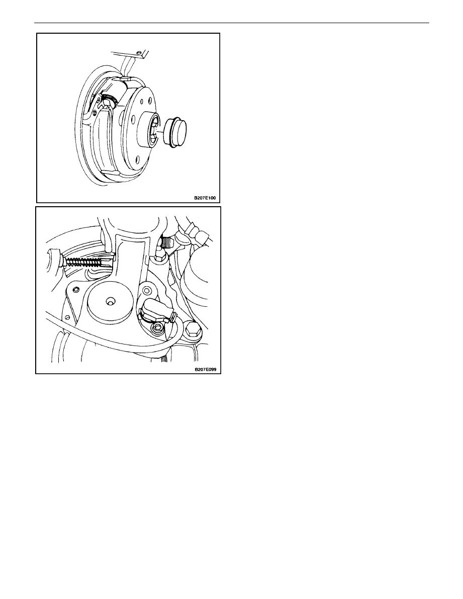
2. Disconnect the parking brake cable from the brake
backplate operating lever.
4E – 8
I
REAR DISC BRAKES
DAEWOO V–121 BL4
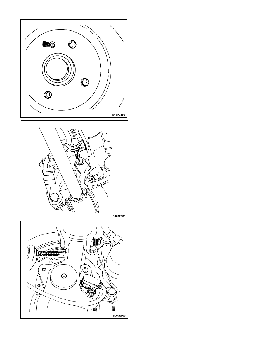
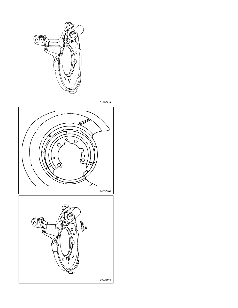
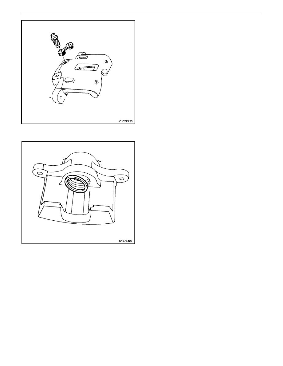
3. Pry off the shaft dust cover.
4. Remove the spindle shaft castle nut.
5. Remove the wheel hub assembly from the spindle
shaft.
6. Remove the bolts that secure the splash shield/
backplate/ parking brake shoe assembly to the
steering knuckle.
7. Remove the splash shield/backplate/parking brake
shoe assembly from the steering knuckle.
REAR DISC BRAKES 4E – 9
DAEWOO V–121 BL4
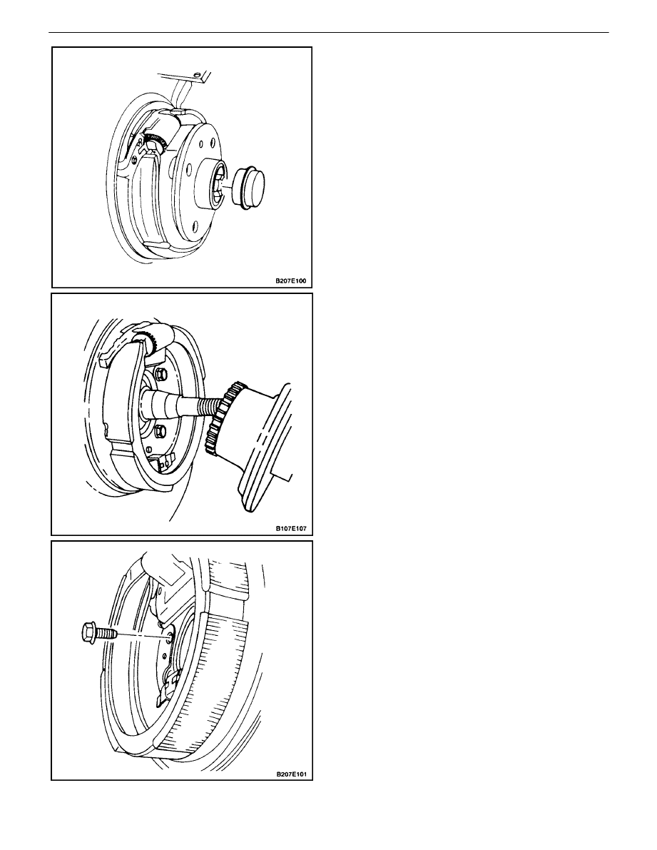
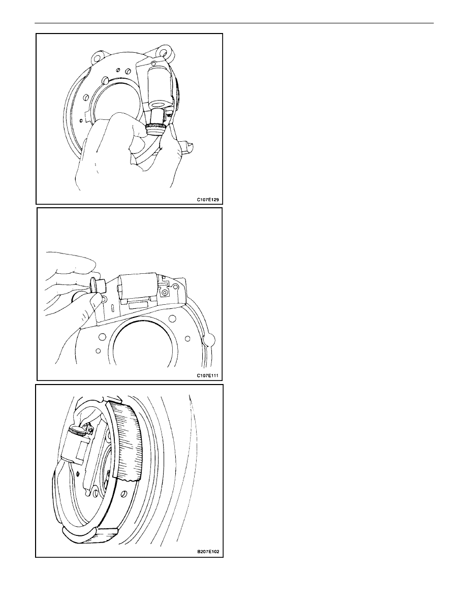
8. Remove the screw that secures the parking brake
shoe hold–down spring assembly to the backplate.
9. Remove the parking brake shoe, sliding it away
from the actuation mechanism.
10. Remove the splash shield.
11. Remove and discard the adjuster screw and the
nut.
4E – 10
I
REAR DISC BRAKES
DAEWOO V–121 BL4
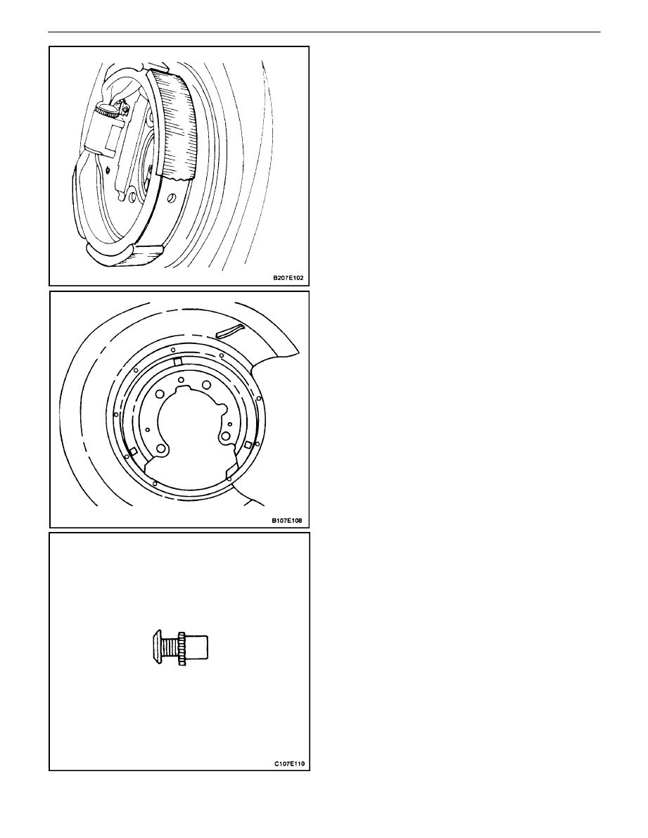
12. Remove and discard the tappet and the pushrod.
13. Using a 3.5 mm (0.14 inch) drill, remove the pop
rivets holding the dust cover assembly and the ad-
juster pawl to the backplate.
14. Remove and discard the dust cover, and the dust
cover retainer from the backplate.
15. Remove and discard the lever and the adjuster
pawl.
REAR DISC BRAKES 4E – 11
DAEWOO V–121 BL4
Installation Procedure
CAUTION : A high flash point oil–free solvent such as
tricloroethylene or acetane, used in cleaning brake
components such as backing plates, is usually highly
flammable and presents health hazards if inhaled for
prolonged periods of time.
1. Clean the backing plate, ensuring the actuation
cavity is free from grease and any other contamina-
tion.
2. Inspect the shoe assembly position. The shoe
should fit centered on the splash shield with the
shoe tips located correctly in the slots.
3. Inspect the splash shield for rust or any other dam-
age. Replace the splash shield, if necessary.
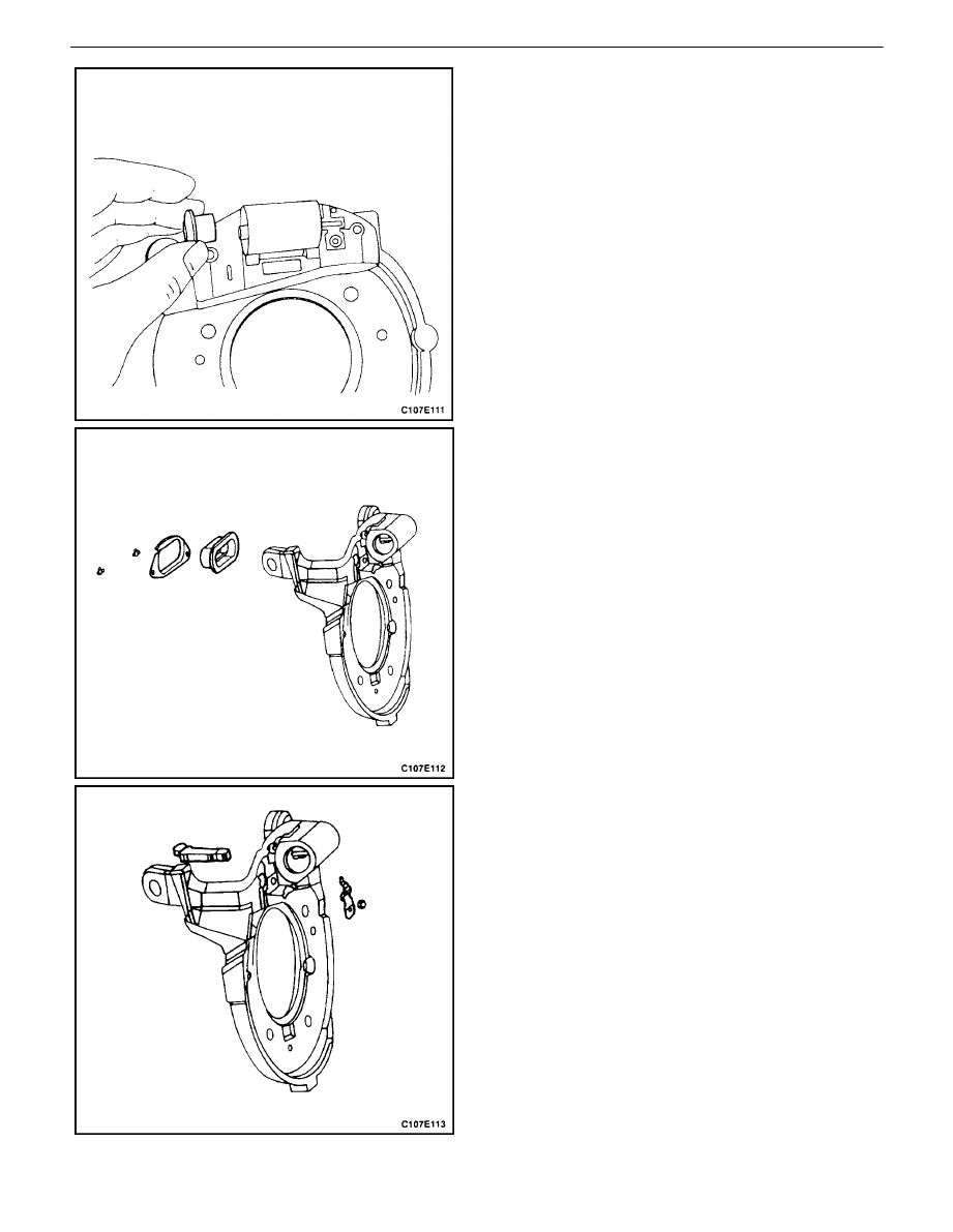
4. Install the new adjuster pawl to the backing plate by
securing it with a pop rivet.

4E – 12
I
REAR DISC BRAKES
DAEWOO V–121 BL4
5. Slide the new dust cover onto the dust cover
notches.
6. Insert the new lever and the dust cover assembly
into the backing plate.
7. Secure the new dust cover retainer using pop riv-
ets.
8. Lubricate the actuation cavity and the tappet with
grease. Ensure that the internal bore of the cavity is
covered with grease.
9. Secure the splash shield and the backplate to the
steering knuckle with the bolts, and secure the
parking brake shoe hold–down spring assembly
with the screw.
Tighten
Tighten the splash shield bolts to 25 N
S
m (18 lb–ft).
Tighten the parking brake shoe hold–down spring as-
sembly screw to 3.5 N
S
m (31 lb–in).
10. Connect the new parking brake adjustment screw
to the new adjustment nut. Tighten the nut to where
it meets the screw, and then back off one–quarter
of a turn.
REAR DISC BRAKES 4E – 13
DAEWOO V–121 BL4
11. Install the adjustment screw and the adjustment nut
into the backing plate actuation mechanism on the
adjustment pawl side. Keep the shoe slot parallel
with the backing plate face.
12. Install the new pushrod into the tappet. Ensure the
pushrod is set correctly in the lever socket by hold-
ing the lever into the backing plate while inserting
the pushrod and the tappet.
13. Clean excess grease using a clean rag.
Important : The shoe assembly must be resting on the
splash shield with the brand side up.
Important : Clean hands are required when handling the
parking brake shoe.
14. Install the parking brake shoe engaging the shoe
tips in both the adjusting screw and the tappet
slots.
4E – 14
I
REAR DISC BRAKES
DAEWOO V–121 BL4
15. Install the wheel hub assembly, and secure it with
the wheel hub assembly–to–spindle shaft castle
nut.
Tighten
Tighten the wheel hub assembly–to–spindle shaft
castle nut to 25 N
S
m (18 lb–ft), plus 1 N
S
m (9 lb–in).
16. Install the shaft dust cover.
17. Install the parking brake cable to the parking brake
lever on each side of the vehicle.
18. Adjust the parking brake. Refer toSection 4G, Park-
ing Brake.
19. Install the rotor. Refer to”Rotor”in this section.
REAR DISC BRAKES 4E – 15
DAEWOO V–121 BL4
UNIT REPAIR
CALIPER OVERHAUL
Disassembly Procedure
1. Remove the caliper. Refer to”Caliper”in this section.
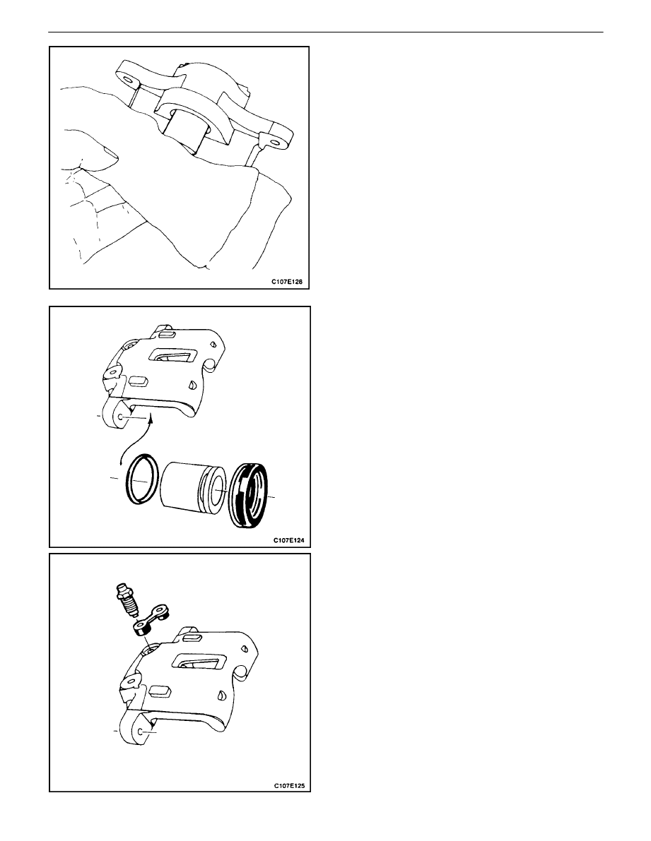
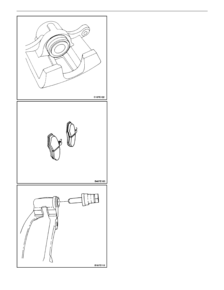
2. To prevent damage to the piston when removing it,
place a clean shop towel between the piston and
the caliper.
CAUTION : When applying air pressure at the caliper
inlet port, do not place fingers in front of the piston.
The piston will pop out of its bore with enough force
to cause serious injury.
3. Apply unlubricated compressed air to the caliper
inlet port, and progressively increase the air pres-
sure until the piston is forced out of the bore.
4. Remove and discard the outer dust seal.
5. Remove the inner seal and discard it. Do not
scratch the piston bore or the seal groove when
removing the inner seal.
6. Remove the bleeder valve and the dust cover.
4E – 16
I
REAR DISC BRAKES
DAEWOO V–121 BL4
Assembly Procedure
CAUTION : Keep alcohol and brake fluid away from
the eyes, as serious injury may result.
CAUTION : Keep rubber seals and brake parts away
from oil. Oil can cause the seals to swell and deterio-
rate, and the braking system could become inopera-
tive.
Important : Do not use a hone or any other procedure to
remove material from the piston or caliper bore.
1. Clean all parts with denatured alcohol or brake
fluid. Dry the parts with unlubricated compressed
air, and blow out all passages in the caliper and the
bleeder valve.
2. Inspect the piston and the caliper for scoring and
corrosion. Replace any components that show
these conditions.
3. Insert the bleeder valve and the dust cover.
Tighten
Tighten the bleeder valve to 11 N
S
m (97 lb–in).
4. Lubricate a new piston inner seal with brake fluid.
5. Install the piston inner seal into the groove in the
cal–iper bore.
REAR DISC BRAKES 4E – 17
DAEWOO V–121 BL4
6. Install the inner seal into the groove in the caliper
bore.
7. Lubricate the piston with brake fluid.
8. Install the piston into the caliper.
9. Install the outer seal into the piston groove. Apply
steady hand pressure until the piston is seated in
the bore.
10. Inspect the brake shoe linings for minimum thick-
ness. Refer to”Lining Inspection”in this section. If
necessary, install new shoes.
11. Inspect the guide pins and boots. If the boots are
damaged, or if the guide pins do not slide easily,
replace these parts. Lubricate the guide pins with a
lithium soap base glycol grease or other grease
which will not deteriorate or swell the rubber boots.
12. Install the caliper. Refer to”Caliper”in this section.

4E – 18
I
REAR DISC BRAKES
DAEWOO V–121 BL4
GENERAL DESCRIPTION
AND SYSTEM OPERATION
DISC BRAKE CALIPER
The caliper has a single bore and it is mounted to a bracket
on the wheel knuckle. Hydraulic pressure, which is trans-
mitted to the piston and the caliper, is created by pressing
the brake pedal. During braking, the piston and the caliper
apply a clamping force on the brake shoes. The vehicle is
stopped as a result of the friction between the rotor and the
brake shoes.
S
When servicing a caliper, replace all parts included
in the caliper repair kit.
S
During caliper overhaul, lubricate the piston and the
inner seal with clean brake fluid to ease assembly.
S
Do not use lubricated shop air on brake parts be-
cause oil will deteriorate rubber seals.
S
If any hydraulic component is removed or discon-
nected, it may be necessary to bleed all or part of
the brake system.
S
Replace the shoes in axle sets only.
S
The torque values specified are for dry, unlubri-
cated fasteners.
S
Perform the service operations on a clean bench
away from oily material.
Wyszukiwarka
Podobne podstrony:
M34e Rear Drum Brakes
Kaspersky Rescue Disk 8 8 1 36 Build 18 03 2010
FRONT DISK BRAKES 4D 11
ARTICLE BRAKES PAD REAR SERVICE
Exploring Economics 4e Chapter 18
akumulator do peugeot 405 ii break 4e 14 16 18
Prezentacja 18
podrecznik 2 18 03 05
9 1 18 Szkolenie dla KiDów
Planowanie strategiczne i operac Konferencja AWF 18 X 07
Przedmiot 18 1
18 piątek
AutomatykaII 18
18 Badanie słuchu fonemowego z uzyciem testu sylab nagłosowychid 17648 ppt
więcej podobnych podstron