®
AQUA PRO
DIGITAL PASSIVE INFRARED DETECTOR
aqua_pro_e 10/06
The microprocessor-based, fully digital AQUA PRO detector is characterized by
high sensitivity and interference resistance. Due to an advanced digital
temperature compensation feature, the device can work in a wide temperature
range. A quad pyroelectric element is used in the detector. The processor
performs two-way signal analysis, based on value and quantity.
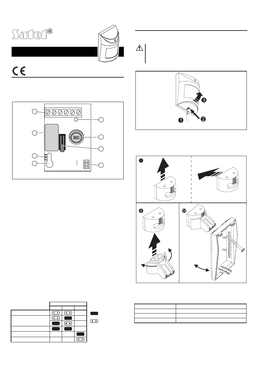
Figure 1. View of detector electronics board.
Explanations to Fig. 1:
1 – terminals:
NC –
relay
(NC)
TMP – tamper
contact
COM – common ground
12V –
supply
input
2 – LED indicator. It lights red for approx. 2 seconds after movement is sensed by
the detector and the alarm relay activated (opening of the NC contacts). This
allows the installer to check the detector for correct functioning and to
approximately determine the protected area.
3 – alarm relay.
4 – pyroelement.
5 – tamper contact.
6 – scale for positioning of pyro element against the lens (see Table 2 and
Figure 4).
7 – fixing screw hole.
8 – pins for setting detector operating parameters (see Table 1).
The detector is provided with a prealarm feature. The prealarm is indicated by
a short flash of the LED for approx. 120ms, but does not activate the relay.
Activation of the prealarm takes place when the detector registered disturbances
in the environment, which do not meet the alarm criterion. The prealarm sensitivity
depends on what sensitivity is set on the detector pins. Frequently occurring
prealarms may cause activation of the alarm relay.
For 30 seconds after the power-up, the detector remains in the starting state,
which is signalized by a rapid LED blinking. Only then the detector enters its
operational readiness state.
The detector monitors the supply voltage. If the voltage drops below 9V (±5%) for
more than 2 seconds, the detector will signal a trouble by activation of the alarm
relay and by steady light of the LED indicator. Restoration of a minimum 9V (±5%)
voltage will turn the signaling off.
Pins
JP1 JP2 JP3
Low sensitivity
Medium sensitivity
High sensitivity
LED indicator ON
LED indicator OFF
Table 1. Programming of working parameters.
Installation
The detector is designed for indoor installation. It can be mounted on the wall,
either directly or on the included holder (the manufacturer recommends mounting
on the holder).
Be careful so as not to soil or damage the pyro element in the
process of installation.
Be careful during installation not to turn the detector towards heat
sources and air-conditioning outlets, as well as objects exposed to
strong solar radiation.
1. Open the housing as shown on Fig. 2.
Figure 2. Removing the cover.
2. Remove the electronics board.
3. Make suitable openings for screws and cable in the rear panel of the housing.
4. Pass the cable through the prepared opening.
5. Fix the rear housing panel to the wall or to the attached holder.
Figure 3. Mounting the detector on the holder.
6. Fasten the electronics board, taking into consideration the height of detector
installation (see Table 2 and Figure 4).
Detector installation height
Scale position in relation to housing indicator
more than 2.1m
center scale mark above the indicator
2.1m
center scale mark in line with the indicator
less than 2.1m
center scale mark below the indicator
Table 2. Positioning of pyroelement in relation to the lens.
7. Connect the leads to the corresponding terminals.
8. Using jumpers, set the working parameters of the detector (see Table 1).
9. Close the detector housing.
- pins shorted
- pins open
NC
TMP
COM 12V
NC
TMP
REL1
JP1
JP2
JP3
PIR SENS.
LED ON/OFF
1
2
3
4
5
7
8
6
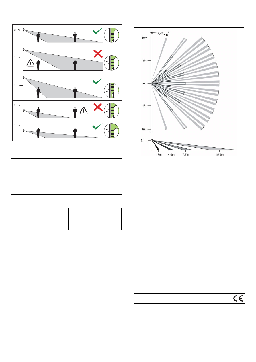
Figure 4. The controlled area depending on the detector installation height and
positioning of pyroelement in relation to the lens for the optimal setting.
Start-up
1. Switch the detector power on. The LED will start blinking (if the JP3 pins are
shorted).
2. When the detector enters the ready state (the LED will stop blinking), carry out
the detector range test, i.e. check that movement within the supervised area
will activate the alarm relay and lighting of the LED.
3. If necessary, change the detector sensitivity (pins JP1 & JP2).
Lenses
An extra wide angle (EWA) lens is installed in the detector, however, it is possible
to replace it by another lens with different characteristics (range, number of
beams, angle of view). The available lenses are described in Table 3.
Lens type
Range
Angle of view
extra wide angle (EWA)
15m
141,2°
long range with access zone
monitoring (LR)
30m
main beam – 3m wide (at the end of
range)
vertical barrier (VB)
22,5m
2.2m wide (at the end of range)
Table 3. Available lenses for AQUA PRO detectors.
Note: The detector operating range should be selected to match the size of
space where the detector will be installed. The size of the space along the
main direction of detector positioning is not to be less than 1/3 the nominal
range of the detector. Improper selection of the lens may cause excessive
sensitivity and trigger false alarms.
Figure 5. Distribution of beams for the EWA lens.
Note:
The effective operating range of the detector can differ from the one,
which is shown at the figure.
Technical data
Nominal supply voltage (±15%)..................................................................... 12V DC
Average current consumption (±10%)............................................................. 9.5mA
Violation signaling time........................................................................................... 2s
Operating temperature range .................................................................. -10...+55°C
Detectable motion speed.............................................................................. do 3 m/s
Dimensions ........................................................................................... 63x96x49mm
Recommended installation height ......................................................................2,1m
SATEL sp. z o.o.
ul. Schuberta 79
80-
172 Gdańsk
POLAND
tel. + 48 58 320 94 00
info@satel.pl
www.satel.pl
The latest EC declaration of conformity and product approval
certificates are available for downloading on website www.satel.pl
Wyszukiwarka
Podobne podstrony:
aqua pro io pl 1109
aqua pro
aqua pro io pl 0711
aqua pro io pl 1109
Mechanika Plynow Lab, Sitka Pro Nieznany
Corel Paint Shop Pro X Obrobka zdjec cyfrowych cwiczenia
httpwww aqua ar wroc plactaplfull42009000040200900008000040002100030
marcinstolp pro
Mechanika Budowli pro 2
AQUA
aqua s io pl 1109
algorytmy, programy, jezyki pro Nieznany (2)
Krakow nowapr1 nowa kryt1,2 pro Nieznany
więcej podobnych podstron