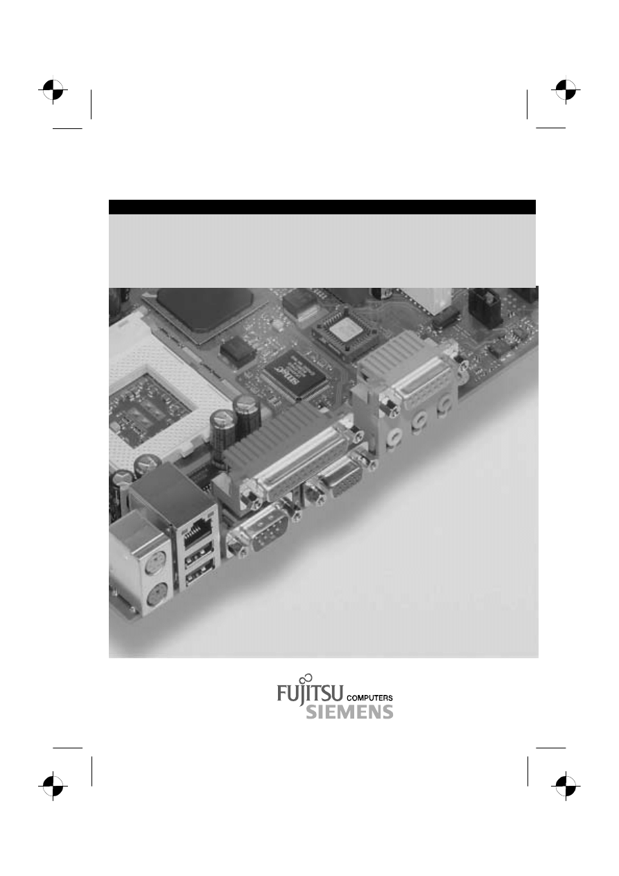
COMPONENT
.com
Technisches Handbuch / Technical Manual
System Board D1302
Memory Expansion Board D1303

Are there ...
... any technical problems or other questions you need clarified?
Please contact:
·
your sales partner
·
your sales outlet
You will find further information in the manual "Safety, Guarantee and Ergonomics".
The latest information on our products, tips, updates, etc., can be found on the Internet under:
http://www.fujitsu-siemens.com


Dieses Handbuch wurde auf Recycling-Papier gedruckt.
This manual has been printed on recycled paper.
Ce manuel est imprimé sur du papier recyclé.
Este manual ha sido impreso sobre papel reciclado.
Questo manuale è stato stampato su carta da riciclaggio.
Denna handbok är tryckt på recyclingpapper.
Dit handboek werd op recycling-papier gedrukt.
Herausgegeben von/Published by
Fujitsu Siemens Computers GmbH
Bestell-Nr./Order No.:
A26361-D1302-Z120-1-7619
Printed in the Federal Republic of Germany
AG 1001 10/01
A26361-D1302-Z120-1-7619
SYSTEM BOARD D1302
TECHNICAL MANUAL

SYSTEM BOARD D1302
Technical Manual
Introduction
Important Notes
Features
Internal Interfaces and
Connectors
Jumper Setting and
Connectors
Add-on Modules
BIOS Setup
Onboard SCSI BIOS
Utility
Beep Codes
Glossary
November 2001 edition

Copyright
ã
Fujitsu Siemens Computers GmbH 2001
Intel, Pentium and Celeron are registered trademarks and MMX, OverDrive and Xeon are
trademarks of Intel Corporation, USA.
Microsoft, MS, MS-DOS and Windows are registered trademarks of Microsoft Corporation.
PS/2 and OS/2 Warp are registered trademarks of International Business Machines, Inc.
All other trademarks referenced are trademarks or registered trademarks of their respective owners,
whose protected rights are acknowledged.
All rights, including rights of translation, reproduction by printing, copying or similar methods, even
of parts are reserved.
Offenders will be liable for damages.
All rights, including rights created by patent grant or registration of a utility model or design, are
reserved. Delivery subject to availability.
Right of technical modification reserved.
This manual was produced by
cognitas. Gesellschaft für Technik-Dokumentation mbH
www.cognitas.de

A26361-D1302-Z120-3-7619
Contents
Hardware management features ........................................................................................8
Hardware monitor subsystem.............................................................................................8
Fan control and monitoring ................................................................................................9
Controlling system fan speed .............................................................................................9
Temperature and system monitoring................................................................................10
Recovering System BIOS - Jumper JP9 ..................................................................................13
Clearing the CMOS BIOS Settings - Jumper JP1.....................................................................14
Protecting the System BIOS - Jumper JP16.............................................................................14
Add-on Modules.......................................................................................................................15
Supported Processors .............................................................................................................15
Single Processor:.....................................................................................................................15
Memory Installation..................................................................................................................20
Installing a Network Board with WOL .......................................................................................21
Replacing the Lithium Battery ..................................................................................................22
BIOS Introduction ....................................................................................................................23
Main Menu...............................................................................................................................24
Standard CMOS Features........................................................................................................24
Advanced Boot Option .............................................................................................................25
Advanced Chipset Features.....................................................................................................27
Integrated Peripherals..............................................................................................................28
Power Management Setup.......................................................................................................30
PnP/ PCI Configurations ..........................................................................................................32
Security Features.....................................................................................................................34
CPU Smart Setting ..................................................................................................................36
PC Health Status .....................................................................................................................36

Contents
2
A26361-D1302-Z120-3-7619
Introduction ............................................................................................................................. 37
Configuration Settings ............................................................................................................. 38
Host Adapter Settings ............................................................................................................. 38
Scan and Configure SCSI Devices .......................................................................................... 39
Selectable Boot Settings ......................................................................................................... 40
Restore Default Adapter Settings ............................................................................................ 40
Raw NVRAM Data................................................................................................................... 40
Scan SCSI Bus ....................................................................................................................... 40
SCSI Disk Utility ...................................................................................................................... 40
Select Host Adapter ................................................................................................................ 40

A26361-D1302-Z120-3-7619
1
Introduction
i
Depending on the configuration of your system board, some of the hardware components
described may not be available.
You may find further information in the description "BIOS Setup".
Further information on drivers is provided in the Readme files on hard disk or on the supplied drivers
diskettes or on the "Drivers & Utilities" or "ServerStart" CD.
Notational Conventions
The meanings of the symbols and fonts used in this manual are as follows:
!
Pay particular attention to text marked with this symbol. Failure to observe this warning
may endanger your life, destroy the system, or lead to loss of data.
i
Supplementary information, remarks and tips follow this symbol.
Ê
Text which follows this symbol describes activities that must be performed in the order shown.
Ë
This symbol means that you must enter a blank space at this point.
Ú
This symbol means that you must press the Enter key.
Screen output is set
in this typeface
.
Entries you make via the keyboard are set
in this bold typeface
.
Text in italics
indicates commands or menu items.
"Quotation marks" indicate names of chapters and terms that are being emphasized.

A26361-D1302-Z120-3-7619
3
Important Notes
Keep this manual close to the device. If you pass on the device to third parties, you should also pass
on this manual.
!
Be sure to read this page carefully and note the information before you open the device.
You cannot access the components of the system board without first opening the device.
How to dismantle and reassemble the device is described in the Operating Manual
accompanying the device.
Please note the information provided in the chapter "Safety" in the Operating Manual of
the device.
Incorrect replacement of the lithium battery may lead to a risk of explosion. It is therefore
essential to observe the instructions in the chapter “Replacing the Lithium Battery".
The shipped version of this board complies with the requirements of the EEC
directive 89/336/EEC "Electromagnetic compatibility".
Compliance was tested in a typical PC configuration.
When installing the board, refer to the specific installation information in the
Operating Manual or Technical Manual of the receiving device.
Connecting cables for peripherals must be adequately insulated to avoid interference.
!
Components can become very hot during operation. Make sure you do not touch
components when making extensions to the system board. There is a danger of burns!
i
The warranty is invalidated if the device is damaged during the installation or replacement
of system expansions. Information on which system expansions you can use is available
from your sales outlet or the customer service centre.

Important Notes
4
A26361-D1302-Z120-3-7619
Information on Boards
To prevent damage to the system board or the components and conductors on it, please take great
care when you insert or remove boards. Take care above all to ensure that expansion boards are
slotted in straight without damaging components or conductors on the system board, or any other
components, for example EMI spring contacts.
Be especially careful with the locking mechanisms (catches, centering pins, etc.) when you replace
the system board or components on it, for example memory modules or processors.
Never use sharp objects (screwdrivers) for leverage.
Boards with electrostatic sensitive devices (ESD) are identifiable by the label
shown.
When you handle boards fitted with ESDs, you must observe the following
points under all circumstances:
·
You must always discharge yourself before working (for example, by
touching a grounded object).
·
The equipment and tools you use must be free of static charges.
·
Pull out the power plug before inserting or pulling out boards containing
ESDs.
·
Always hold boards with ESDs by their edges.
·
Never touch pins or conductors on boards fitted with ESDs.

A26361-D1302-Z120-3-7619
5
Features
·
System board in ATX format
·
Dual Intel Xeon™ processor (socket 603) with 100 MHz Front-Side Bus, 400 MHz data transfer
rate and 256 KB second-level cache
Size of third-level cache depends on the processor used
·
Intel i860 chipset
consisting of ICH 2
·
Intel 82550 LAN controller (10/100 Mbps) with RJ45 interface
WOL with Magic Packet
ä
is supported, as is booting from LAN with RPL or Intel PXE
·
AC'97 Audio Code, AD 1881
internal: Stereo CD-In, Stereo AUX-In
external: Mono Micro-In, Stereo Line-In, Stereo Line-Out (max. 2 x 0.5 W/8
W
)
·
Qlogic ISP12160A Ultra 160 SCSI
·
System monitoring and temperature monitoring
·
8 RIMM slots for 256 to 4 GB main memory (RIMM PC800 or PC600) using Memory Expansion
Board (D1303)
·
Flash BIOS
·
Wake-up events
-
Wake on RTC
-
Wake on Ring (Serial Port 1 and 2)
-
Wake on LAN
-
Wake on USB
-
Wake on PCI Cards
·
Energy saving functions:
-
ACPI S1 / Standby (requires an operating system that supports ACPI)
-
ACPI S4 / Save-to-Disk (requires an operating system that supports ACPI)
-
Switching on/off, standby mode, suspend mode via on/off switch
-
Switching on/off via software
·
Security functions:
-
Cover monitoring: The cover monitoring reports when the cover has been opened without
authorization.
-
System and Setup password
-
Parallel and serial ports can be deactivated
-
Virus protection function for the hard disk boot sector
·
3 PCI slots 32-bit / 33 MHz and 2 PCI slots 64-bit / 66 MHz
PCI slots 32-bit / 33 MHz support 5.0 V, and PCI slots 64-bit / 66 MHz support 3.3 V main and
auxiliary voltages.
·
1 AGP slot
AGP slot supports 4x AGP and AGP Pro 50 modes. AGP slot supports 1.5 V AGP boards only.
·
The system board supports AC Power Loss Recovery.
Features
6
A26361-D1302-Z120-3-7619
·
IDE hard disk controller connected to PCI bus for up to four IDE drives
(e.g., IDE hard disk drives, ATAPI CD-ROM drives)
The IDE hard disk controller is ATA33/66/100 and ultra DMA mode capable
·
Floppy disk drive controller (possible formats: 720 KB, 1.44 MB)
·
The system board supports booting from a 120 MB IDE floppy disk drive (LS-120)
·
1 external parallel port (ECP- and EPP-compatible)
·
2 external serial ports (16C550-compatible with FIFO)
·
1 internal WOL interface
·
2 external PS/2 ports for keyboard and mouse
·
4 external USB ports
·
Real-time clock/calendar with integrated battery backup
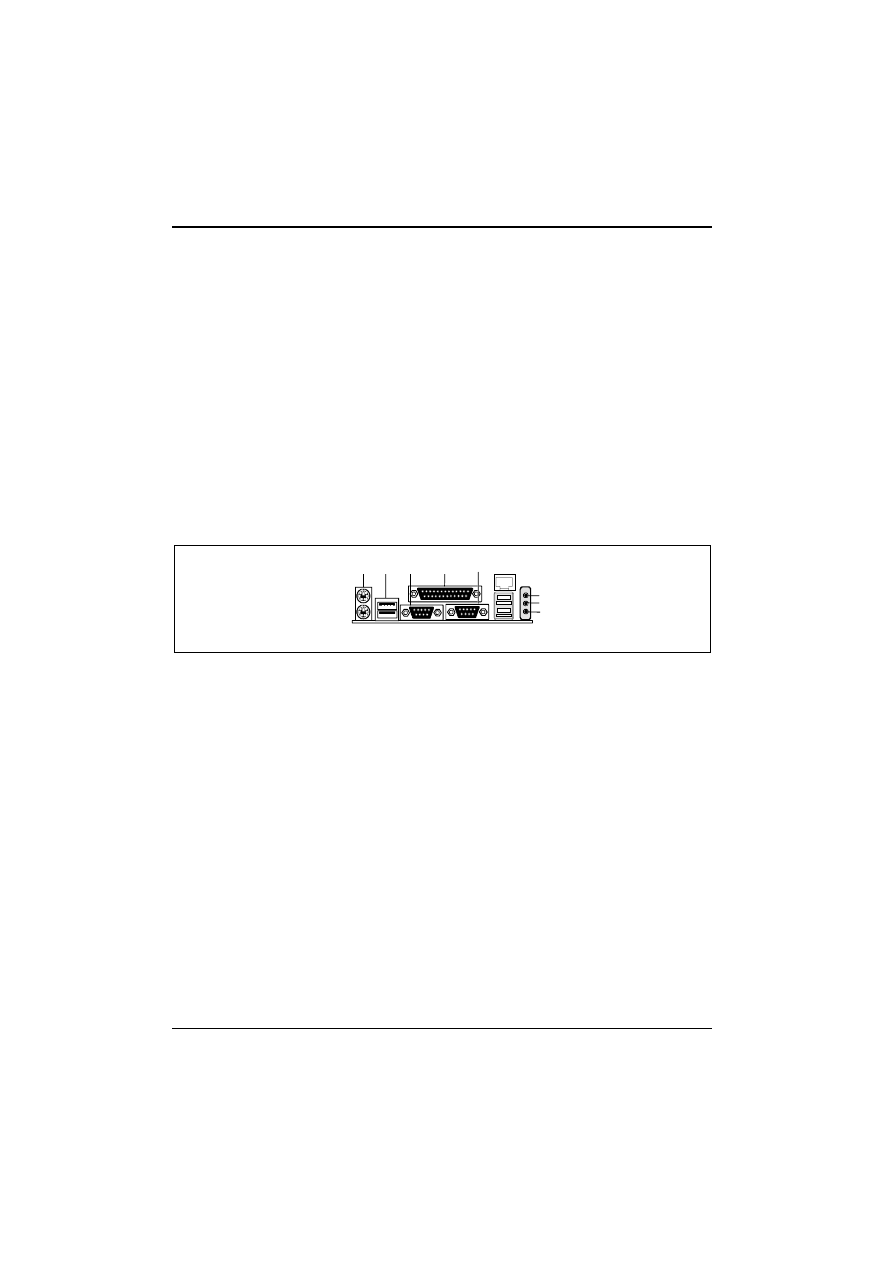
External Connectors
2
3
1
5
6
7
8
9
4
10
11
12
1 =
PS/2 mouse port
2 =
PS/2 keyboard port
3 =
USB port 1
4 =
USB port 2
5 =
Serial port 1
6 =
Parallel port
7 =
Serial port 2
8 =
LAN port
9 =
USB ports 3 and 4
10 =
Audio Line-In
11 =
Audio Line-Out
12 =
Audio Micro-In
A26361-D1302-Z120-3-7619
7
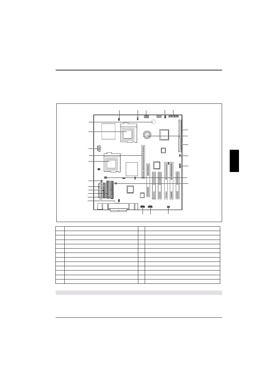
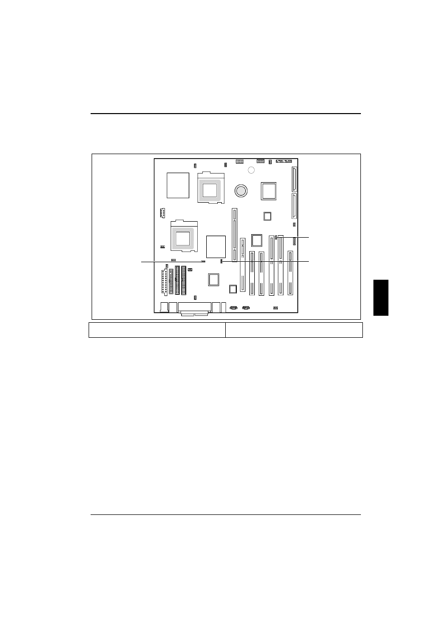
Internal Interfaces and Connectors
The picture shows the location of the major components on the system board.
PC
I 1
PC
I 2
PC
I 3
PC
I6
4
1
P
C
I64 2
AGP Pr
o
1
2
3
4
5
6
7
8
9
13
14
15
16
17
18
19
20
21
22
24
23
25
10
11
12
26
1
CPU 0 fan connector
14 Aux-In connector
2
Upper front system fan 2 connector
15 CD-ROM connector
3
USB internal header
16 CPU 1 fan connector
4
Lower front system fan 3 connector
17 Primary IDE connector
5
Front panel connector
18 Secondary IDE connector
6
Ultra-160 SCSI connector B
19 Diskette Drive connector
7
Battery
20 WTX power connector A
8
Ultra-160 SCSI connector A
21 Rear system fan 1 connector
9
Chassis intrusion connector
22 CPU 1 socket
10
SCSI activity LED input
23 Memory expansion card connector (MECC)
11
Temperature sensor for front system fan 2
24 WTX power connector B
12
Temperature sensor for rear system fan 1
25 CPU 0 socket
13
Temperature sensor for front system fan 3
26 Internal speaker
The components and connectors marked are not necessarily present on the system board.

Internal Interfaces and Connectors
8
A26361-D1302-Z120-3-7619
Temperature Monitoring / System Monitoring
Hardware management features
The hardware management features enable the board to be compatible with the Wired for
Management (WfM) specification. The board has several hardware management features, including
the following:
·
Hardware monitor subsystem
·
Chassis intrusion connector
·
Fan control and monitoring
Hardware monitor subsystem
The hardware monitor subsystem provides low-cost instrumentation capabilities. The features of the
hardware monitor subsystem include:
·
Management Level 5 functionality
·
Microprocessor system hardware monitor (Winbond W83627HF)
·
Integrated temperature and voltage monitoring to detect levels above or below acceptable
values (Vcore, 1.8V, 3.3 V, 5 V, 12 V, -12V, 5Vsb).
·
Access through the SMBus
·
Internal ambient temperature sensing through an onboard thermistor
·
Chassis intrusion connector
Voltage monitoring:
The voltages Vcore, 1.8V, 3.3V, 5V, 12V, -12V and the 5Vsb are monitored.
With hardware monitoring—regardless of the operating system and processor—the advantages
compared to conventional software monitoring are clear:
-
Suitable for all operating systems and processor types
-
No additional load on processor (performance)
-
Optimum temperature protection, even if process faults or faults are present in the
operating system
-
Optimum noise reduction

Internal Interfaces and Connectors
A26361-D1302-Z120-3-7619
9
Fan connector descriptions
Connector
Function
Provides +12 VDC for a system or chassis fan
Supports speed control
System Fan 1, 2, 3
A tachometer feedback connection is also provided
Provides +12 VDC for processor fan
The processor fan is always on
Speed control is not supported
Processor 0/1 Fan
A tachometer feedback connection is provided
Fan control and monitoring
The system board includes five fan power connectors: two connectors for fans on the processor heat
sinks and three connectors for speed-controlled system fans. All five connectors are 3-pin headers.
All fans support fan tachometer monitoring, but only the system fans are speed controlled.
The system fans use the system board fan speed control which consists of three states: off, normal
speed, and high speed. In normal operation, the system fans operate at normal speed until the
thermal sensor junction temperature reaches the high-speed fan threshold temperature. The system
fans operate at high speed when the temperature threshold is exceeded.
This threshold temperature can be set in the BIOS Setup.
The user can set the threshold to 28°C for continuous operation of the system fans in high-speed
mode in the S0 and S1 sleep states.
Controlling system fan speed
·
Set the
Auto Fan Startup Temperature
to the minimum temperature.
·
Adjust the
Range
as the working range of fans.
·
The fans will be changed to automatic speed between the minimum and maximum temperature
as set.
Fan monitoring:
Fans that are no longer available, blocked, or sticky fans are detected.
Fan control:
The fans are regulated according to temperature and the BIOS settings.

Internal Interfaces and Connectors
10
A26361-D1302-Z120-3-7619
Temperature and system monitoring
Hardware monitoring
Supports voltage sensing to detect out-of-range values
Supports speed monitoring for five and control for three fans
Supports three temperature monitors
Supports chassis intrusion detection
One goal of temperature and system monitoring is to reliably protect the computer hardware against
damage caused by overheating. In addition, it prevents unnecessary noise by reducing fan speeds
and provides information about the system state. The chassis intrusion detection protects the system
against unauthorized opening.
The temperature and system monitoring is controlled by Winbond W83627HF and ADM 1031.
The following functions are supported:
Temperature monitoring:
Measurement of both processor temperatures and of the system temperature with three onboard
temperature sensors.
Temperature control:
The temperature is controlled with the fan speed of the three system fans.
Cover monitoring:
Unauthorized opening of the cover is detected, even when the system is switched off. However, this
will not be indicated until the system is switched on again.

Internal Interfaces and Connectors
A26361-D1302-Z120-3-7619
11
Hard Disk Connection
An Ultra ATA/66 or ATA/100 hard disk must be connected with a cable especially designed for the
ATA/66/100 mode.
Ê
Connect the cable end marked blue to the system board.
LAN Port
This system board is equipped with the Intel 82550 LAN controller. This LAN controller supports the
transfer speeds 10 Mpbs and 100 Mpbs. The LAN controller supports the WOL function through
Magic Packet
ä
.
It is also possible to boot a device without its own boot hard disk via LAN. Here, RPL and Intel PXE
are supported.
The LAN RJ45 connector is equipped with a yellow and a green light emitting diode (LED).
1
2
1 =
Green indicator
2 =
Yellow indicator
Green
ON
100 Mbps
Green
OFF
10 Mbps
Yellow
ON
LAN link established
Yellow
OFF
LAN link not established
Yellow
Blinking
Traffic on the LAN

A26361-D1302-Z120-3-7619
13
Jumper Settings and Connectors
PC
I 1
PCI
2
PC
I 3
PC
I6
4
1
P
C
I64 2
AGP Pr
o
1
2
3
1 =
JP1
2 =
JP16
3 =
JP9
Recovering System BIOS - Jumper JP9
Jumper JP9 enables recovery of the system BIOS after an attempt to update has failed. To restore
the system BIOS you need a Flash BIOS Diskette (please call our customer service centre).
Furthermore it allows you to start the system with CPU speed in safe mode (800 MHz).
1-2
Normal operation (default setting).
2-3
CPU safe mode: 800 MHz.
OFF
The system BIOS boot block restores the system BIOS from an inserted "Flash BIOS
Diskette" in floppy drive A: (no LS-120).

Jumper Settings and Connectors
14
A26361-D1302-Z120-3-7619
Clearing the CMOS BIOS Settings - Jumper JP1
For further information refer to chapter "BIOS Setup".
1-2
Normal operation (default setting).
2-3
CMOS
Protecting the System BIOS - Jumper JP16
1-2
Flash BIOS protection through BIOS setup (default setting).
2-3
Flash BIOS hard protection: no flash BIOS update possible.
OFF
No Flash BIOS update protection.
A26361-D1302-Z120-3-7619
15
Add-on Modules
!
Whenever you perform any of the steps described in this section you must first remove
the device’s power plug from the power outlet.
Even when you have turned off the device, parts of it (memory modules, AGP and PCI
expansion boards, etc.) may still be energized.
Supported Processors
This section describes the processors supported by the system board D1302 and how to install
them.
i
The system board D1302 only supports Intel Xeon processors with a host bus speed of
100 MHz. If two processors are installed, both processors must run at the same core
frequency speed. Installing processors of different core frequency speeds may damage
the system board and processors.
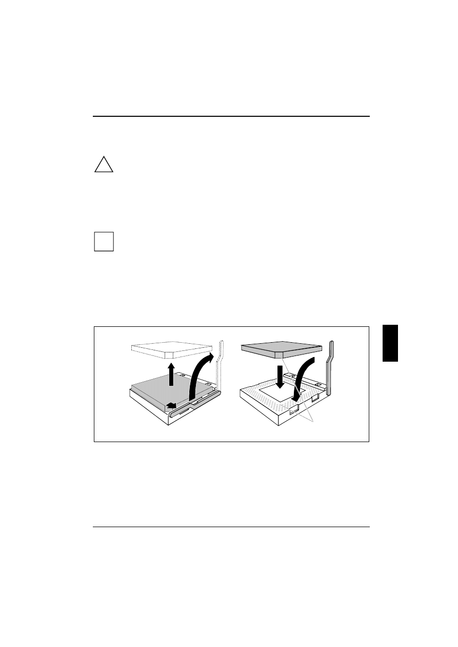
Single Processor:
Install the processor in the socket marked ‘CPU0’.
Installing/removing a processor
3
2
1
A
4
5
Ê
Remove the heat sink.
Ê
Press the retainers in the direction of the arrows (1) and (2) and tilt it upwards.
Ê
Remove the processor (3).
Ê
Insert the new processor in the socket so that the angled corner of the processor matches the
coding on the socket (A) with regard to its position (4).
System Board and Retainer Installation
16
A26361-D1302-Z120-3-7619
!
The angled corner of the processor may be covered by the heat sink. In this case, let
yourself be guided by the marking in the rows of pins on the underside of the processor.
Ê
Apply the heat transfer compound evenly on the underside of the heat sink (approx. 0.5 mm).
Ê
Tilt the retainers downwards and press in the direction of the arrow (5) until it engages.
Ê
Fit the heat sink on the new processor.
Dual Processors
The following values must be identical for both processors:
·
Host bus speed
·
Processor core frequency
·
Cache size
·
Operating voltages
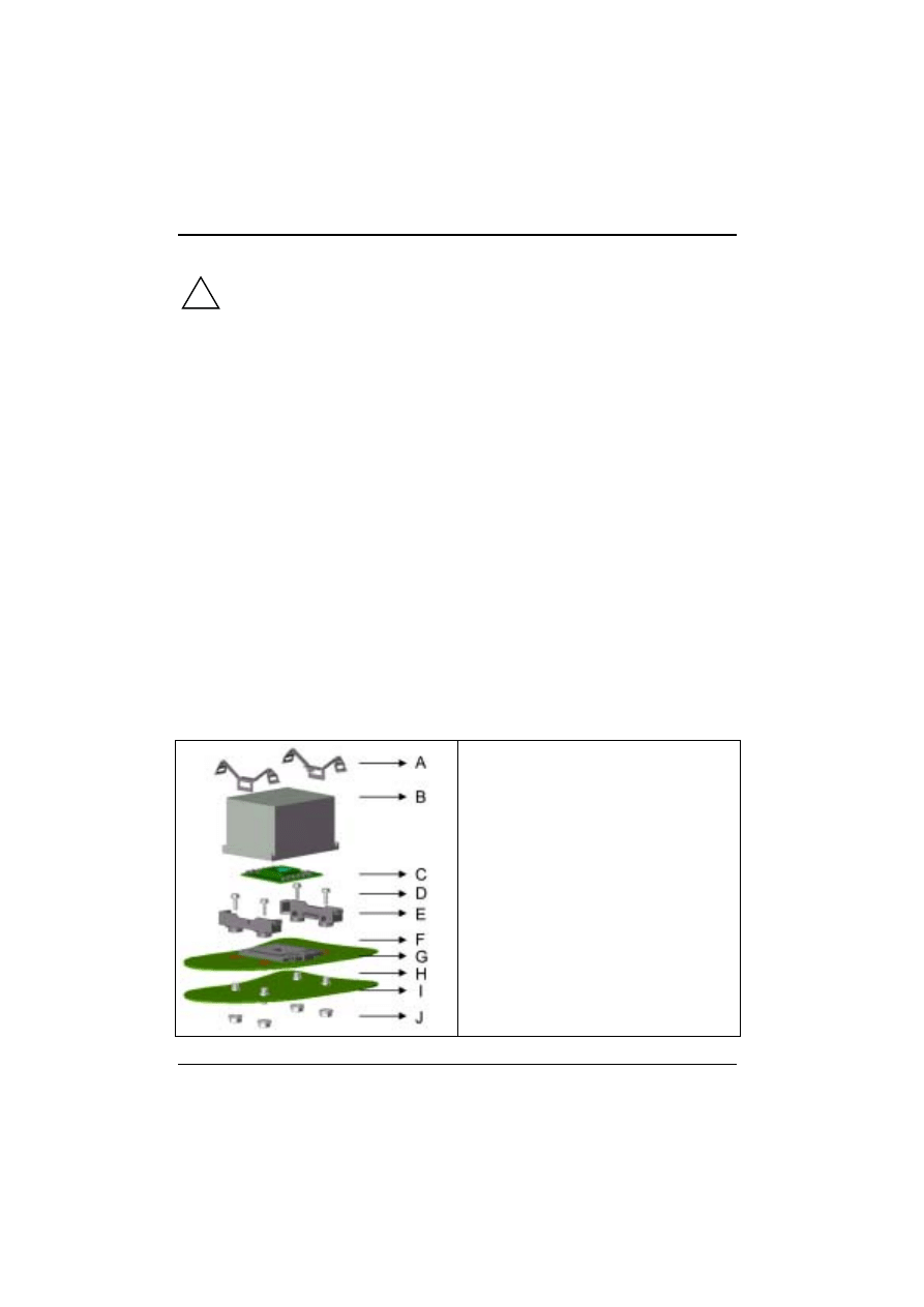
There are three major steps about the Intel Xeon processor installation for a system board D1302.
Ê
System board and retainer installation.
Ê
Processor installation.
Ê
Heat sink installation.
System Board and Retainer Installation
To install the system board on the chassis, you should first examine the way faster retainers (E) are
affixed.
Please follow the steps below to fix the retainer (E) on the system board (G).
Screws:
Support the system board (G) on the chassis
after you have attached nuts (J) and screws (H)
to the chassis (I).
Use screws to attach the retainer (E) to the
chassis (I) through the system board (G) so that
the retainer (E) will be affixed to the system
board.

System Board and Retainer Installation
A26361-D1302-Z120-3-7619
17
Processor installation
There is a handle at the side of Socket 603 (F) that you must pull up before you insert the processor
(C).
Ê
Be sure to align the pins correctly and insert the processor(C).
Ê
Press down the handle of Socket 603 (F)
Illustration of CPU installation
Heat sink installation
Before you install a heat sink (B), make sure that the processor (C) has been installed.
Ê
Put some thermo grease on the bottom of the heat sink (B) or affix a thermo pad (B).
Ê
Place the heat sink (B) on the processor (C) and make sure that they contact each other well
either via the thermo grease or the thermo pad.
Ê
Connect the clips (A) on the side-edge of heat sink.
Ê
Push both ends of clip (A) until they click on the fastener retainer (E).
System Board and Retainer Installation
18
A26361-D1302-Z120-3-7619
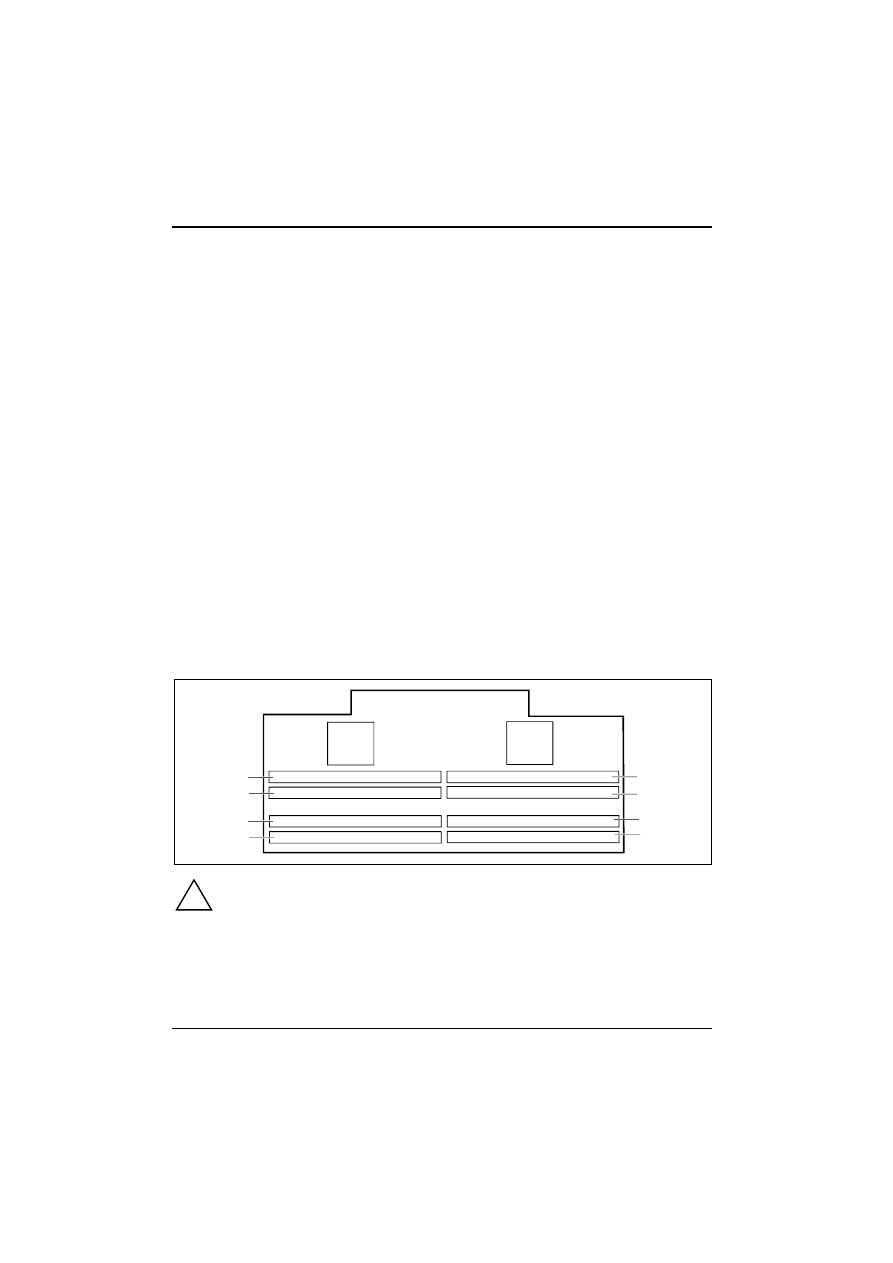
Upgrading Main Memory
D1303 memory expansion board usage
The memory expansion board D1303 (with two memory repeater hubs) supports the following
memory features:
·
Up to eight 2.5V, 184-pin RDRAM* interface memory modules (RIMMs*)
·
300/400 MHz direct RDRAM* interface
·
Support for PC600 and PC800 RDRAM*
·
4GB maximum capacity with RIMMs using 256-megabit technology
·
Single- or double-sided RIMM configurations
·
Non-ECC (16-bit) and ECC (18-bit) memory
·
Support for 64-Mb,128-Mb and 256-Mb RDRAM* technologies
These slots are suitable for 128 to 512 MB RDRAM memory modules of the RIMM format. The
permissible total size of the main memory is 4 GB.
You must not combine memory modules from different manufacturers, different types of modules, or
modules of different capacities in the same bank. Different memory capacities are permitted in the
various banks. Example: 2 x 128 MB in bank 0 and 2 x 64 MB in bank 1 are permissible; 64 MB +
128 MB in bank 0 are not permissible.
D1303 memory expansion board
The D1303 memory expansion board contains two memory channels in which a total of eight RIMMs
sockets can be installed.
J3
J1
J5
J7
J2
J4
J6
J8
!
All locations must always be occupied. Missing memory modules must be replaced
with a C-RIMM. This C-RIMM should then be installed in the order nearest to the
terminators.

System Board and Retainer Installation
A26361-D1302-Z120-3-7619
19
RIMM installation combinations
J8
J6
J4
J2
J7
J5
J3
J1
2 modules
RDRAM CRIMM
CRIMM
CRIMM
CRIMM
CRIMM
RDRAM CRIMM
4 modules
RDRAM CRIMM
RDRAM CRIMM
RDRAM CRIMM
RDRAM CRIMM
6 modules
RDRAM RDRAM RDRAM CRIMM
RDRAM CRIMM
RDRAM RDRAM
8 modules
RDRAM RDRAM RDRAM RDRAM RDRAM RDRAM RDRAM RDRAM
!
You must install identical memory modules in each of the following pairs of slots:
J2 and J5
J4 and J7
J1 and J6
J3 and J8
!
The system board supports PC800 and PC600 memory modules. Always use memory
modules of the same speed class. You should not mix memory modules that have
different speed classes. Optimal system speed is achieved when you use 4 or 8 PC800
RDRAM memory modules.
System Board and Retainer Installation
20
A26361-D1302-Z120-3-7619
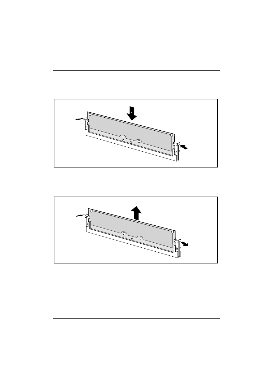
Memory Installation
Installing memory modules
2
2
Ê
Flip the retaining clips on both sides of the relevant slot outwards.
Ê
Insert the memory module into the slot (1).
Ê
At the same time, flip the retaining clips upwards until the memory module snaps into place (2).
Removing a memory module
1
1
2
Ê
Flip the retaining clips at the ends of the slot outwards (1).
Ê
Pull the memory module out of its slot (2).

System Board and Retainer Installation
A26361-D1302-Z120-3-7619
21
Installing a Network Board with WOL
Ê
Install the network board as described in the operating manual for your unit.
Ê
Push the WOL cable onto the WOL plug connector of the system board.
i
To use a network board’s WOL functionality, the power supply must provide a 5 V
auxiliary voltage of at least 1 A. If the system board was not already installed in a unit
when you bought it, you must check whether your power supply can provide the auxiliary
voltage.
You may find further information in the documentation for the network board.
System Board and Retainer Installation
22
A26361-D1302-Z120-3-7619
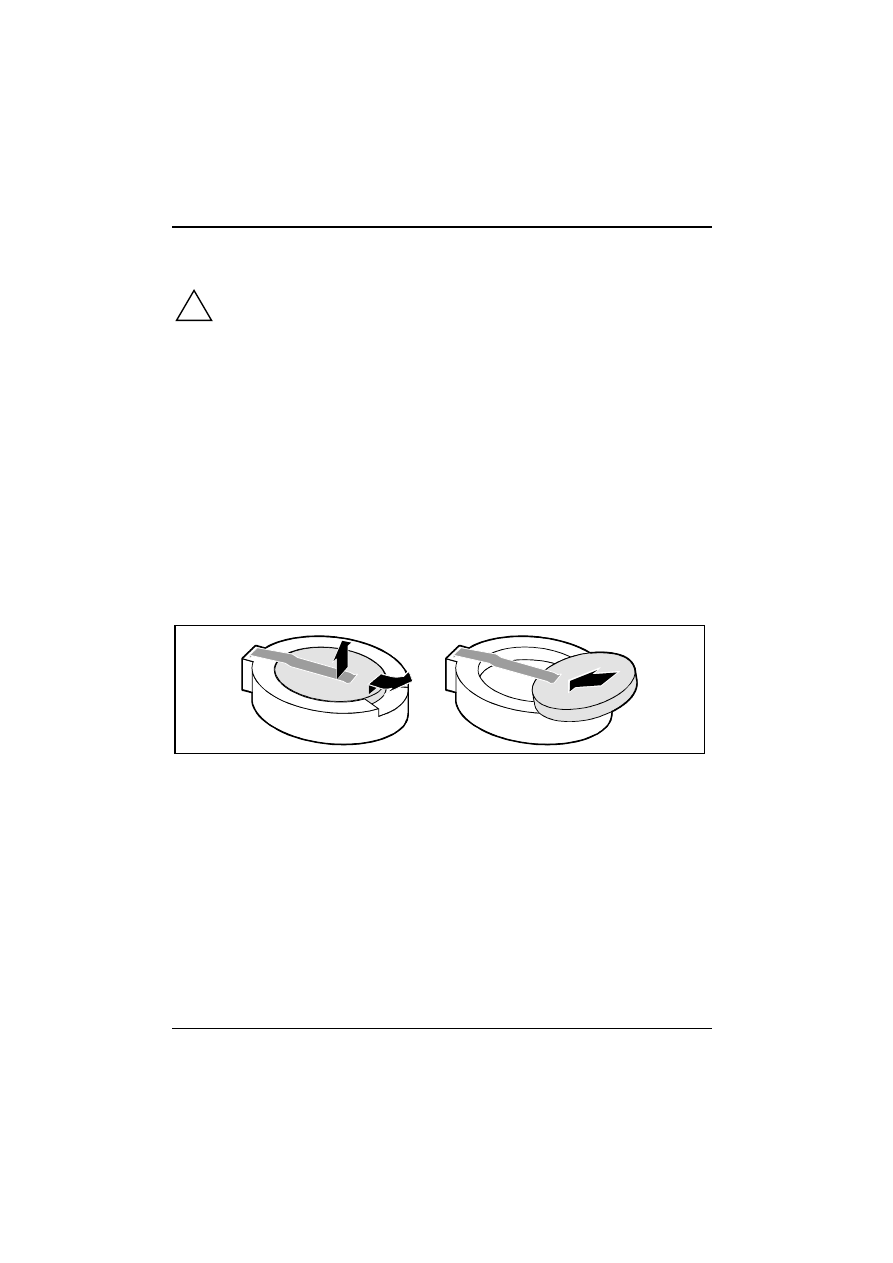
Replacing the Lithium Battery
!
Incorrect replacement of the lithium battery may lead to a risk of explosion.
The lithium battery must be replaced with an identical battery or a battery type
recommended by the manufacturer (CR2032).
Do not throw lithium batteries into the trash. They must be disposed of in accordance with
local regulations concerning special waste.
Make sure that you insert the battery with the side up. The plus pole must be on the top!
·
VAROITUS
Paristo voi räjähtää, jos se on virheellisesti asennettu. Vaihda paristo ainoastaan
laitevalmistajan suosittelemaan tyyppiin. Hävitä käytetty paristo valmistajan ohjeiden
mukaisesti.
·
VARNING
Explosionsfara vid felaktigt batteribyte. Använd samma batterityp eller en ekvivalent
typ som rekommenderas av apparattillverkaren. Kassera använt batteri enligt
fabrikantens instruktion.
·
ADVARSEL
Lithiumbatteri - Explosionsfare ved fejlagtig håndtering. Udskiftning må kun ske med
batteri af samme fabrikat og type. Lever det brugte batteri tilbage til leverandøren.
·
ADVARSEL
Explosionsfare ved feilaktig skifte av batteri. Benytt samme batteritype eller en
tilsvarende type anbefalt av apparatfabrikanten. Brukte batterier kasseres i henhold
til fabrikantens instruksjoner.
1
2
+
+
3
+
+
Ê
Raise the contact (1) a few millimetres and remove the battery from its socket (2).
Ê
Insert a new lithium battery of the same type in the socket (3).

A26361-D1302-Z120-3-7619
23
BIOS Setup
i
If the description of the BIOS Setup does not agree with your BIOS Setup, then you must
update your BIOS Setup. You can update your system BIOS with the flash BIOS update
(BIOS updates can be found on the Internet under
http://www.fujitsu-siemens.com
).
BIOS Introduction
Using BIOS Setup program
Up
Move to the previous field
Down
Move to the next field
Left
Move to the field on the left hand side
Right
Move to the field on the right hand side
<Esc>
Quit from setup program without saving changes, or exit from current menu
page and return to main menu page
<PgUp> or
<+>
Select the previous value for a field
<PgDn> or <-
>
Select the next value for a field
<F1>
General help
<F2>
Item help
<F5>
Previous values
<F6>
Fail-safe defaults
<F7>
Optimised defaults
<F10.
Save the current value and exit the setup program
If the system is no longer able to boot after changing the settings, the only way to recover it is to
clear the data stored in the RTC CMOS. To reset the RTC CMOS data, take the JP1 jumper cap off
pins 1-2, place it onto pins 2-3, and then place it back onto pins 1-2 again. This will return the RTC to
the default setting. Then, start the BIOS Setup program and select your appropriate settings.
BIOS Setup
24
A26361-D1302-Z120-3-7619
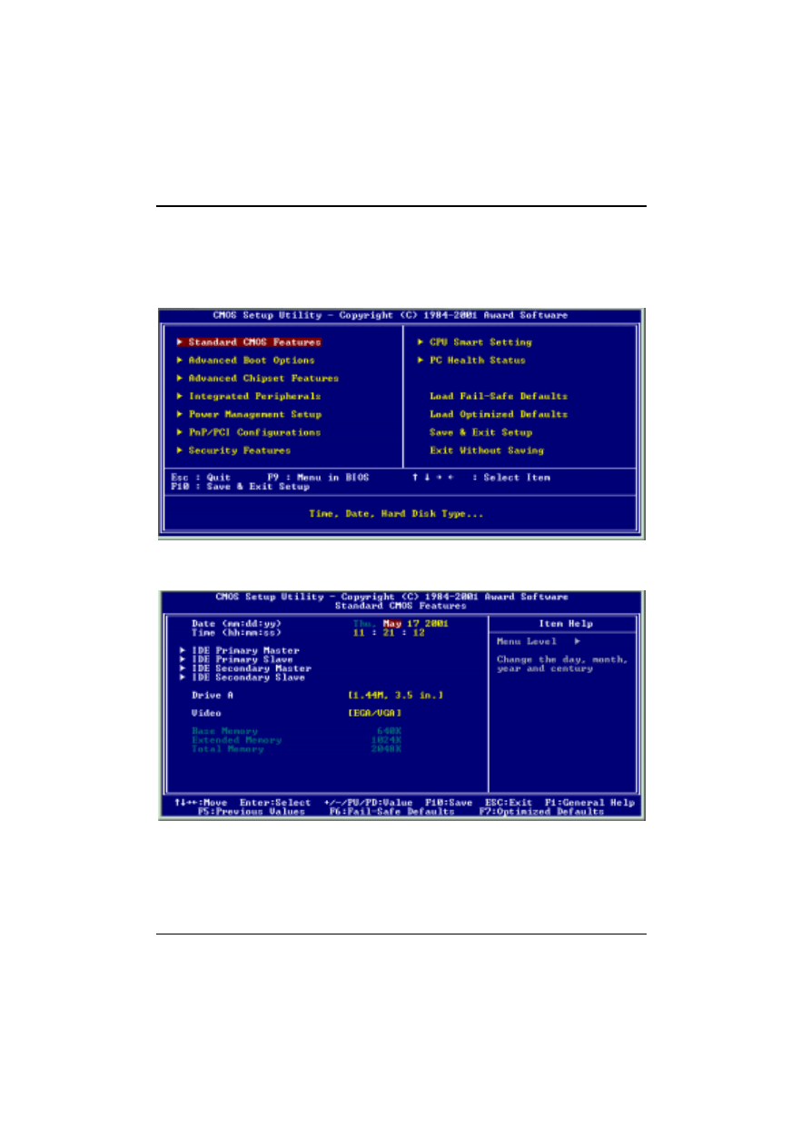
Main Menu
The main menu allows you to select options from several Setup pages. Use the arrow keys to select
among these pages and press the <Enter> key to enter the submenu. A brief description of each
highlighted selection appears at the bottom of the screen.
Standard CMOS Features
Date:
·
This field specifies the current date. The date format is <month>:<day>:<year>.
BIOS Setup
A26361-D1302-Z120-3-7619
25
Time:
·
This field specifies the current time. The time format is <hour>:<minute>:<second>. The time is
calculated based on the 24-hour (military-time) clock.
IDE Primary Master / Primary Slave / Secondary Master / Secondary Slave:
·
Press “Enter” to open the next page for detailed hard drive settings.
IDE HDD Auto-Detection:
·
Auto-detect the HDDs capacity and its parameters, e.g., cylinders, heads and sectors.
·
IDE Primary Master / Primary Slave / Secondary Master / Secondary Slave:
·
This field specifies the type of drive that corresponds to the drive installed in your system. If you
select User, please specify the correct number of cylinders, heads, and sectors.
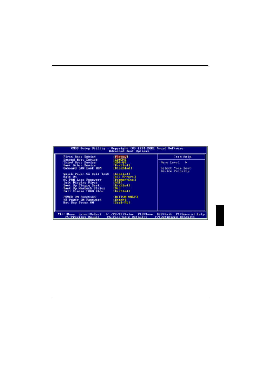
Advanced Boot Option
First / Secondary / Third Boot Device:
The BIOS attempts to load the operating system from the devices in the sequence specified for
these items.
Onboard LAN Boot ROM:
Disable (default). When enabled, the system is able to boot from the LAN.
Quick Power On Self Test:
This field allows the system to skip certain tests while booting. This will decrease the time needed to
boot the system. Enabled, Disabled (default)

BIOS Setup
26
A26361-D1302-Z120-3-7619
Halt On
<All Errors>: If the self-test detects an error, system start-up is aborted after the self-test, and the
system is halted.
<All but Keyboard/Mouse> If the self-test detects an error, system start-up is aborted after self-test
except Keyboard/Mouse error.
<All but Floppy> If the self-test detects an error, system start-up is aborted after self-test except
Keyboard/Mouse error.
<All but Keyboard/Floppy/Mouse> If the self-test detects an error, system start-up is aborted after
self-test except Keyboard/Mouse error.
<No Error>: The system start-up is not aborted. The error is ignored as far as possible.
AC PWR Loss Recovery:
This allows you to specify how you want your system to reboot after the power has been interrupted.
< Always-Off > Leaves your system off.
< Always-on > Starts your system
< Former-Sts > Sets your system back to the state it was before the power interruption.
Init Display First:
This item allows you to decide which slot to activate first. AGP (default), PCI Slot.
Boot Up Floppy Seek:
Seeks disk drives during boot up. Disabling speeds boot-up.
Boot Up Num Lock Status
This field determines the configuration of the numeric keypad after system boot-up. If on, the number
keypad uses number keys. If off, the number keypad uses arrow keys.
Full Screen Logo Show:
Enabled (default) shows the system logo. Disabled doesn’t show the logo.
Power-on Function
This field configures the Power-on mode of the system.
Password:
You can assign a password string via the KB Power-On password field.
Hot KEY:
You can assign a hot key through the Hot Key Power-On field. Pressing this hot key will power- on
your system.
Any Key:
Power On System by pressing any key on the Keyboard.
Button only(default):
Simply power-on your system by pressing the Power-On button on the front panel of your PC case.
Keyboard 98:
Enables Keyboard 98 function. The function is good only for users of Keyboard 98.
BIOS Setup
A26361-D1302-Z120-3-7619
27
Keyboard Password Power-on
In you wish to use this function, move the cursor to the field labelled Enter, then press <Enter>. The
computer will display the message ‘Enter Password’. Type your password and press <Enter>. After
the message ‘Confirm Password’ is displayed, re-type your password. The KB Power-on function will
be in effect after you save and exit the Setup program.
To disable a password, move the cursor to the ‘Enter’ field again, then press <Enter>. The computer
will display the message ‘Enter Password’. Press <Enter>. A message will confirm that the password
is disabled.
Hot Key Power-on:
This field specifies the key selection for the Keyboard-Power-on hot key.
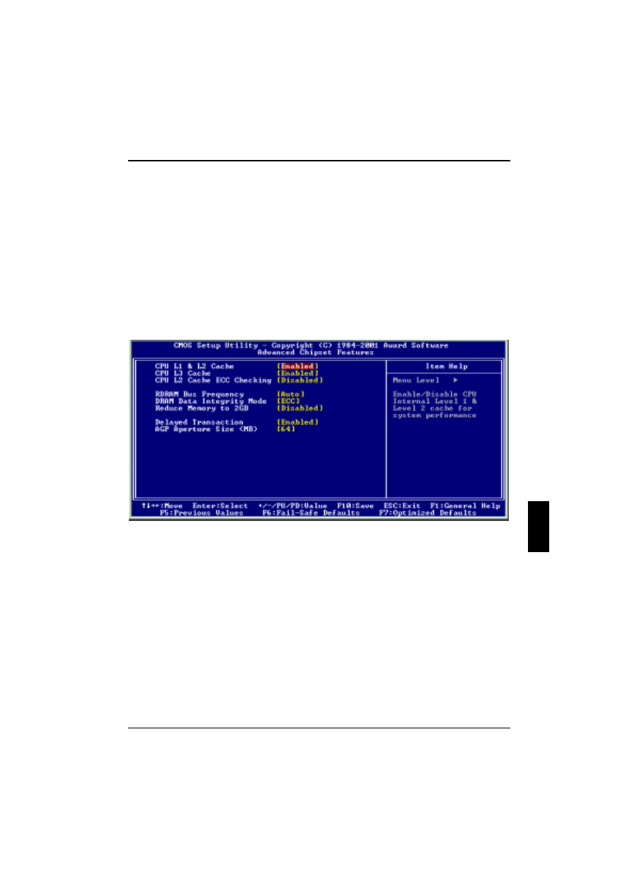
Advanced Chipset Features
This Setup page is used to specify advanced features available through the chipset. The default
settings have been chosen carefully for most operating conditions. DO NOT change the value of any
field on this Setup page without fully understanding the consequences.
CPU L1 & L2 Cache
This field configures the CPU L1 & L2 cache [Enabled (default), Disabled]
CPU L2 Cache ECC Checking:
This function controls the ECC capability in the CPU level 2 cache.
Configuration option: [Enable, Disabled (default)]
CPU L3 Cache:
This field configures the CPU L3 cache [Enabled (default), Disabled]
BIOS Setup
28
A26361-D1302-Z120-3-7619
RDRAM Bus Frequency:
This function sets frequency of RDRAM memory. [Default is Auto]
DRAM Data Integrity Mode:
[Default is ECC]
Reduce Memory to 2GB:
This function should be set to Enabled during installation of Windows NT 4.0 with more than 2 GB
memory in the system. After applying Windows NT Service Pack 3 or later this function can be set to
Disabled again. [Enabled, Disabled (default)]
Delayed Transaction:
When enabled, the south bridge ICH2 will support the Delayed Transaction mechanism when it is the
target of a PCI transaction. [Enabled (default), Disabled]
AGP Aperture Size (MB):
This field configures the main memory size for AGP graphics data used. 64MB (default)
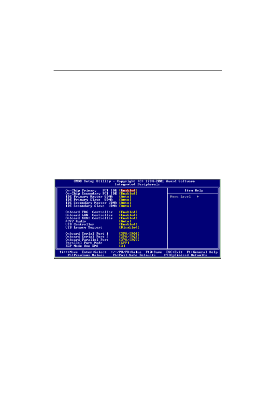
Integrated Peripherals
On-Chip Primary PCI IDE / On-Chip Secondary PCI IDE
Enabled (default); Disabled
This field allows you to enable and disable the built-in PCI IDE hard disk controller(s). The
associated interrupts will only be available if no IDE hard disk drive is physically connected.
Enabled
The PCI IDE drive controller is enabled.
Disabled
The PCI IDE hard disk controller is disabled.

BIOS Setup
A26361-D1302-Z120-3-7619
29
IDE Primary Master / Slave UDMA
If you select Auto, the IDE controller uses the Ultra DMA 33/66/100 mode to access Ultra DMA-
capable IDE devices, depending on the negotiation with your HDD. The maximum transfer rate of
Ultra DMA 100 mode is 100 MBPS. [Auto (default), Disabled]
Onboard SCSI Controller:
Enables/disables the onboard SCSI controller. [Enabled (default), Disabled]
Onboard LAN Controller:
This field enables or disables the onboard LAN controller. [Enabled (default), Disabled]
Onboard FDC Controller:
This field enables or disables the onboard floppy disk controller. [Enabled (default), Disabled]
AC97 Audio:
Auto allows the system board’s BIOS to detect whether you are using any AC97audio device. If an
audio device is detected, the onboard audio controller will be enabled. If no audio device is detected,
the onboard audio controller will be disabled. If you want to use different controller cards to connect
audio connectors, set this option to disabled. [Disabled, Auto (default)]
USB Controller:
Select Enabled if your system contains USB peripherals. [Enabled (default), Disabled]
USB Legacy Support:
Select Enabled if your system contains USB peripherals in Legacy mode. [Enabled,
Disabled (default)]
Onboard Serial Port 1/2:
These fields configure the onboard serial ports. There are several port addresses and IRQ channels
to select from.
3F8/IRQ4 (default)
Port address 3F8h, IRQ4
2F8/IRQ3
Port address 2F8h, IRQ3
3E8/IRQ4
Port address 3E8H, IRQ4
2E8/IRQ3
Port address 2E8h, IRQ3
Auto
BIOS assigns port address and IRQ channel automatically.
Disabled
Disables serial port
BIOS Setup
30
A26361-D1302-Z120-3-7619
Onboard Parallel Port:
This field configures the onboard parallel port. There are several port addresses and IRQ channels
to select from.
378/IRQ7 (default)
Port address 378h, IRQ7
278/IRQ5
Port address278h, IRQ5
3BC/IRQ7
Port address 3BCh,IRQ7
Disabled
Disables parallel port
Parallel Port Mode:
This field configures the operating mode of an onboard parallel port. Make sure that you know the
specifications of your parallel port devices before you select one of these options. [SPP (default),
EPP, ECP, ECP+EPP]
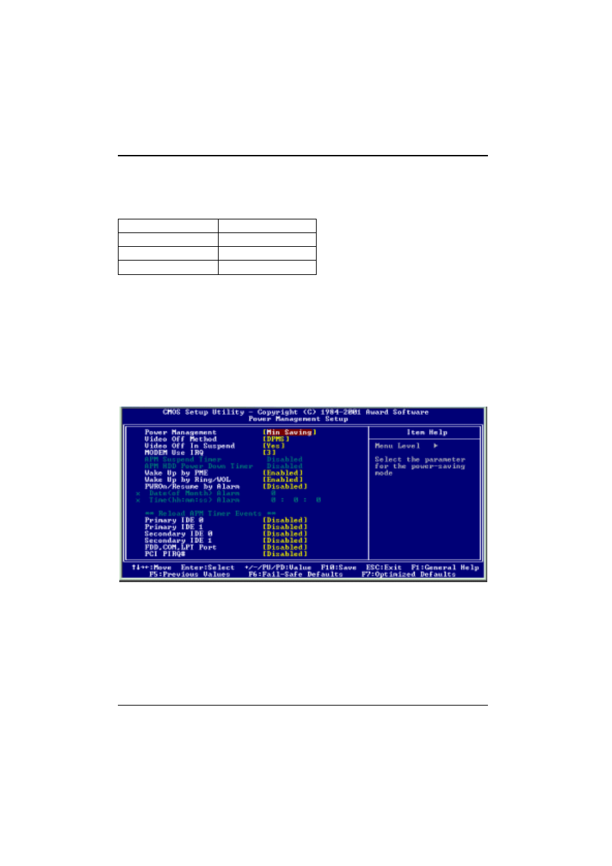
Power Management Setup
Each power-saving mode has a respective timer. The value of each timer can be assigned or
reloaded and will be counted down to zero. When the timer equals zero, the system will be forced
into the corresponding suspend or power-saving mode. If any predefined signal or event is detected
during the timer countdown, the timer restarts automatically.
This feature allows the user to select the default parameters for the power-saving mode.

BIOS Setup
A26361-D1302-Z120-3-7619
31
Power Management:
Min Saving
When idle for one hour, the system enters suspend mode
Max Saving
When idle for fifteen minutes, the system enters suspend mode.
User Define (default)
User can specify the time when the system enters suspend
mode.
Video off Method:
V/H SYNC +Blank (default)
Turns off the vertical and horizontal synchronization ports and
writes blanks to the video buffer.
Blank Screen
Writes blanks to the video buffer only.
DPMS
Initial display power management signalling with DPMS.
Video Off In Suspend:
This determines the manner in which the monitor is blanked. [NO, Yes (default)]
MODEM Use IRQ:
This determines the IRQ which the MODEM can use. [3 (default), 4, 5, 7, 9, 11, NA]
APM Suspend Timer:
This field specifies when the system enters power-saving mode. It is available only when the Power
Management field is set to User Define. [1Min, 2Min, 4Min, 8Min, 12Min, 20Min, 30Min, 40Min,
1Hour, Disabled(default)]
APM HDD Power Down Timer:
This field specifies when the system enters HDD power down. It is available only when the Power
Management field is set to User Define. [1Min, 2 Min, 3Min, 4Min, 5 Min, 6 Min, 7 Min , 8Min, 9 Min ,
10 Min, 11 Min, 12 Min, 13Min, 14 Min, 15 Min, Disabled (default)]
Wake up by PME:
When Wake up by PME (Power Management Enable) is enabled, the PC can power-on via the
onboard LAN controller.
Wake up by RING/WOL:
When Wake up by RING/WOL function is enabled, the PC can power-on via a LAN adapter
connected to the WOL header on the system board or through a modem connected on COM1 or
COM2 (Serial 1 or Serial 2).
Power On/Resume by Alarm:
When enabled, you can set the date and time to automatically power-on your PC (similar to an alarm
clock).
Enabled
Sets the date (0-31) and time (hr, min, sec) to power-on the PC. When the
date is set to 0, the timer is set for every day.
Disabled (default)
Disables the RTC alarm function.
BIOS Setup
32
A26361-D1302-Z120-3-7619
Reload APM Timer Events:
This field enables the system to detect activity and restart the power-saving mode timer.
Primary IDE 0:
If enabled, the timer restarts whenever the master disk of the primary IDE channel is active.
[Enabled, Disabled (default)]
Primary IDE 1:
If enabled, timer restarts whenever the slave disk of the primary IDE channel is active. [Enabled,
Disabled (default)]
Secondary IDE 0:
If enabled, timer restarts whenever the master disk of the secondary IDE channel is active. [Enabled,
Disabled (default)]
Secondary IDE 1:
If enabled, timer restarts whenever the slave disk of the secondary IDE channel is active. [Enabled,
Disabled (default)]
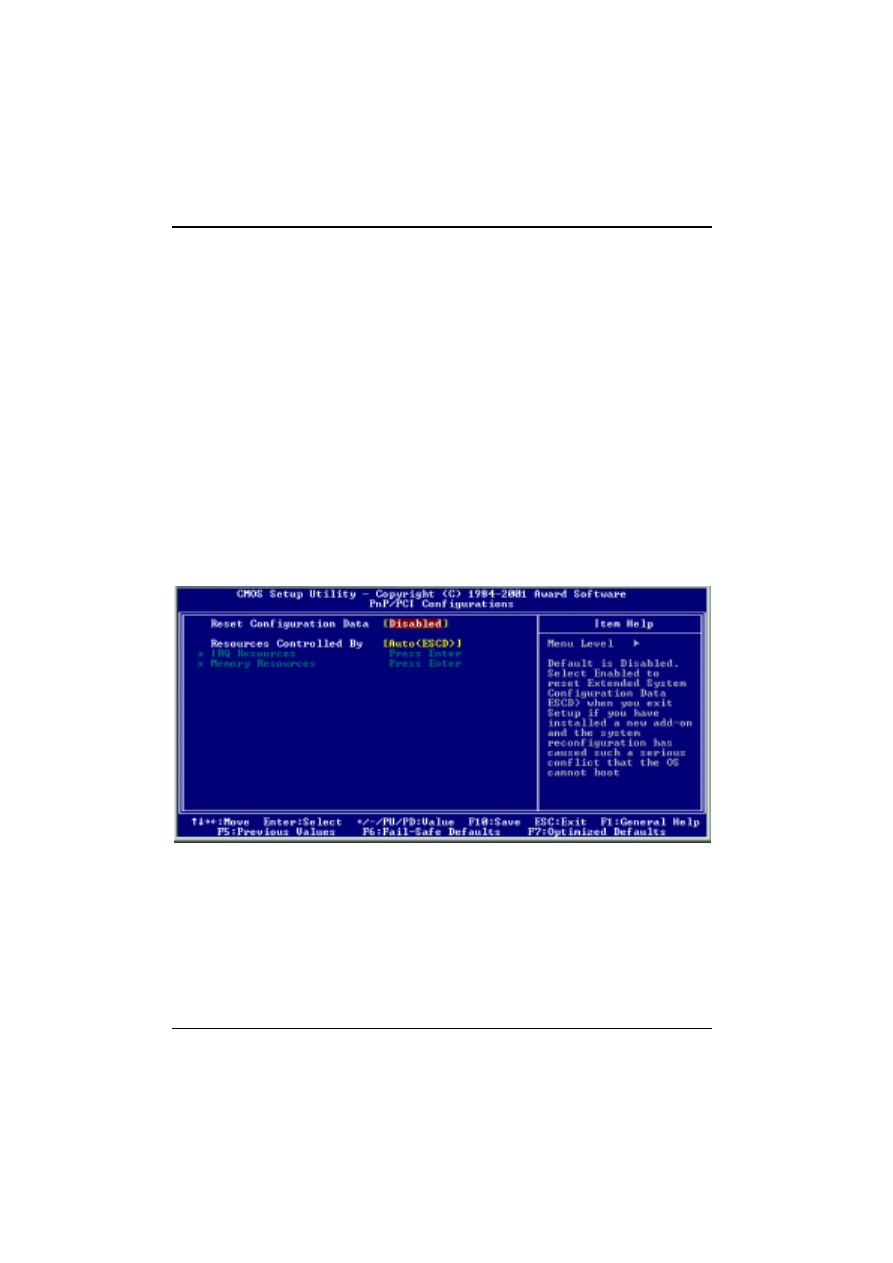
PnP/ PCI Configurations
Reset Configuration Data:
Normally, you leave this field as Disabled. Select Enabled to reset Extended System Configuration
Data (ESCD) when you exit Setup if you have installed a new add-on and the system reconfiguration
has caused such a serious conflict that the operating system cannot boot. [Enabled, Disabled
(default)]

BIOS Setup
A26361-D1302-Z120-3-7619
33
Resources Controlled By:
The Award Plug-and-Play BIOS has the capacity to automatically configure all of the boot and Plug-
and-Play-compatible devices. However, this capability means absolutely nothing unless you are
using a Plug-and-Play operating system such as Windows98/95/NT. If you set this field to Manual,
choose specific resources by going into each of the submenus that follow this field.
Manual
Resources controlled by the user
Auto (ESCD) (default)
Resources controlled by BIOS automatically.
IRQ Resources:
When resources are controlled manually, assign to each system interrupt a type, depending on the
type of device using the interrupt. IRQ3/4/5/7/9/10/11/12/14/15 assigned to [PCI Device Reserved
(default)]
Reserved Memory Base:
Reserves a low memory for the legacy device (non-PnP device). [C800, CC00 , D000, D800, DC400,
N/A (default)]
Reserved Memory Length:
Reserves a low memory length for the legacy device (non-PnP device). [8K (default), 16K, 32K, 64K]
BIOS Setup
34
A26361-D1302-Z120-3-7619
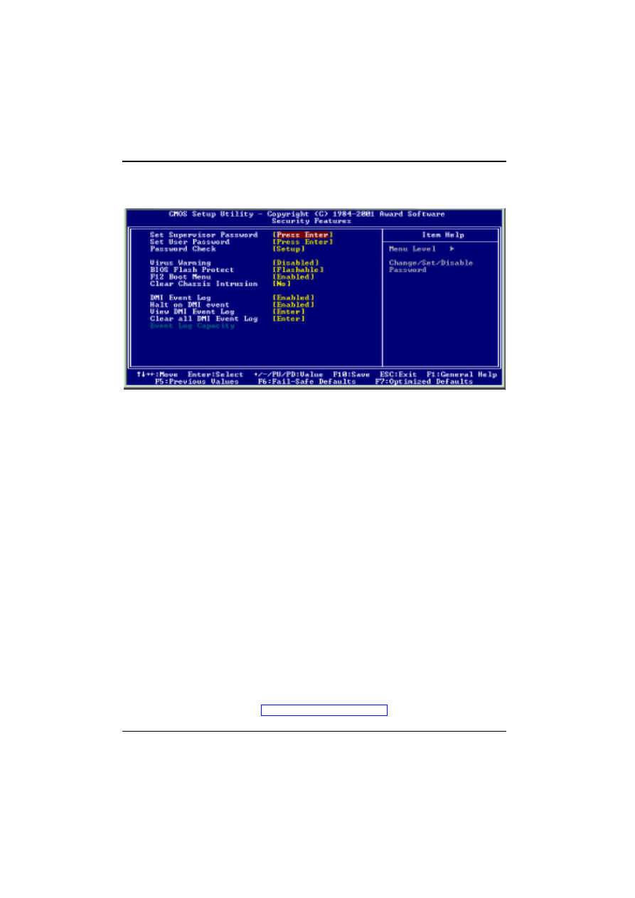
Security Features
Set Supervisor / User Password Setting / Password Check
These Setup pages are used for setting passwords. When a password has been enabled and the
Password Check field is set to Setup, you will be required to enter the password each time you try to
enter the BIOS Setup program. This prevents an unauthorized person from changing any part of
your system configuration. Additionally, if the Password Check field is set to Boot, the BIOS will
request a password every time your system boots. This prevents unauthorized use of your computer.
If you wish to use this function, move the cursor to this field and press <Enter>. The computer will
display the message, “Enter Password”. Type your password and press <Enter>. After the message
“Confirm Password” is displayed, re-type your password. The Supervisor Password function will be
in effect after you save and exit the Setup program.
To disable a password, move the cursor to this field and press <Enter>. The computer will display
the message, “Enter Password”. Press <Enter>. A message will confirm that the password is
disabled. Once the password is disabled, the system will boot and you can enter the Setup program
freely.
Virus Warning
When this function is enabled, the BIOS monitors the boot sector and partition table of the hard disk
drive for any attempt of modification. If an attempt is made, the BIOS will halt the system and display
an error message. Afterwards, if necessary, you can run an anti-virus program to locate and remove
the problem before any damage occurs.
Many disk diagnostic programs will attempt to access the boot sector table, which can cause the
above warning message. If you run such a program, we recommend that you first disable the Virus
Warning function beforehand.
[Enabled, Disabled (default)]
BIOS Flash protect
<Flashable>
Flashing of BIOS is possible if jumper JP16 is set to position 1-2.
<Non-Flash>
BIOS is protected against flashing.
For further information see chapter "Jumper Settings and Connectors".

BIOS Setup
A26361-D1302-Z120-3-7619
35
F12 Boot Menu
<Enabled>
Allows the user to access the Boot Menu by pressing F12 at BIOS POST (default).
<Disabled>
Prevents the user from entering the Boot Menu.
Clear Chassis Intrusion
Set this option to Yes to clear the chassis intrusion information on next reboot. After reboot, this
option will change back to No automatically.
[No (default), Yes]
DMI Event Log
<Enabled>
DMI Event Logging is activated.
<Disabled>
DMI Event Logging is deactivated.
Halt on DMI event
Enable this option to force the system to halt at BIOS POST if the DMI Event Log is not empty.
[Enabled (default), Disabled]
View DMI Event Log
Displays the DMI Event Log.
Clear All DMI Event Log
Choose this option to clear the DMI Event Log.
Event Log Capacity
Shows whether or not space is available for the DMI event logging.
BIOS Setup
36
A26361-D1302-Z120-3-7619
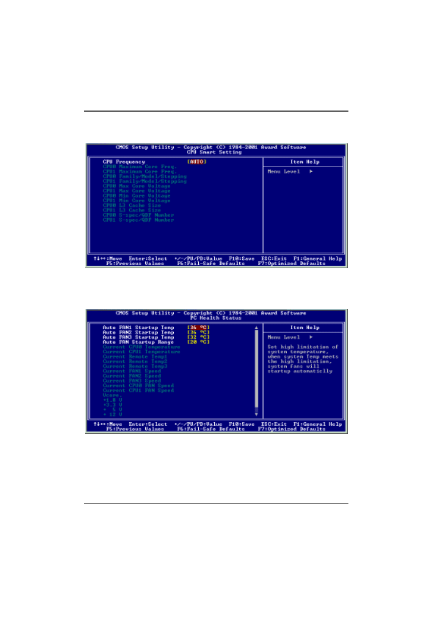
CPU Smart Setting
CPU smart setting allows users to change the CPU frequency.
PC Health Status
This page monitors the status of your computer. CPU/system temperatures, fan speeds and voltages
are displayed.
A26361-D1302-Z120-3-7619
37
Onboard SCSI BIOS Utility (SCSI BIOS Setup)
Introduction
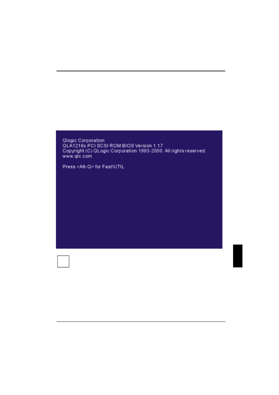
The onboard SCSI controller can be configured with the SCSI BIOS Setup. You access the SCSI
BIOS Setup by pressing <ALT>-<Q> during the onboard SCSI BIOS initialisation (it may take a few
seconds for the SCSI BIOS Setup menu to appear).
i
If the configuration settings are incorrect, your onboard SCSI controller will not function
properly.
The following sections describe the SCSI BIOS Setup options.
Onboard SCSI BIOS Utility (SCSI BIOS Setup)
38
A26361-D1302-Z120-3-7619
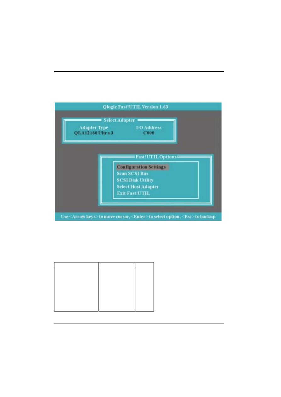
Configuration Settings
The first item on the Fast !UTIL Options menu is Configuration Settings. These settings configure the
SCSI devices and the onboard SCSI controller to which they are attached.
Host Adapter Settings
From the Configuration Settings menu in SCSI BIOS Setup, select Host Adapter Settings.
The default settings for the onboard SCSI host are listed in Table A-1 and are described in the
following paragraphs.
Table A-1: Host adapter settings
Setting
Options
Default
Host Adapter BIOS
PCI DMA Burst
CDROM Boot
Adapter Configuration
Drivers Load RISC code
>4Gbyte Addressing
Fast Command Posting
Enabled or Disabled
Enabled or Disabled
Enabled or Disabled
Auto, Manual, Safe
Enabled or Disabled
Enabled or Disabled
Enabled or Disabled
Enabled
Enabled
Disabled
Auto
Enabled
Disabled
Enabled

Onboard SCSI BIOS Utility (SCSI BIOS Setup)
A26361-D1302-Z120-3-7619
39
Host Adapter BIOS
When this setting is disabled, the ROM BIOS on the Onboard SCSI is disabled, freeing space in
upper memory. The RAM BIOS and other drivers still recognize the Onboard SCSI.
Do not disable this setting if you are booting from a SCSI disk drive attached to the Onboard SCSI.
The default is Enabled.
PCI Bus DMA Burst
When this setting is enabled, burst transfers are performed. When this setting is disabled, data is
transferred in nonburst mode, with each cycle initiated by a new address phase. The default is
Enabled.
CDROM Boot
When this setting is enabled, the ROM BIOS boots from the attached SCSI CD-ROM if a bootable
CD-ROM is installed. If no bootable CD-ROM is found, the system boots from the first bootable SCSI
drive. When this setting is disabled, the ROM BIOS does not boot from the CD-ROM. The default is
Disabled.
Drivers Load RISC Code
When this setting is enabled, the Onboard SCSI uses the RISC firmware that is embedded in the
software driver. When this setting is disabled, the software driver loads the latest version of RISC
firmware found on the system. The default is Enabled.
i
The driver being loaded must support this setting. If the driver does not support this
setting, the result is the same as disabled, regardless of the setting. Leaving this option
enabled guarantees a certified combination of software driver and RISC firmware.
Scan and Configure SCSI Devices
i
You must set the Adapter Configuration setting in the Host Adapter Settings to Manual
to use Auto configure; otherwise, all changes made with Auto configure are reset when
your system is rebooted.
The onboard SCSI is designed to sense and configure the devices connected to your system board.
With the Adapter Configuration set to Manual, the Auto-configure option gives you control of when
the bus is scanned and configured.
Selecting the Auto-configure SCSI Devices option from the Configuration Settings menu causes the
onboard SCSI to scan the devices on the SCSI bus and set the following options, based on the
capabilities of each device:
Enable Device
Negotiate Wide
Tagged Queuing
Disconnects
Negotiate Synchronous
Enable LUN Support
If you use Auto configure to configure your system, you should run SCSI BIOS Setup and select
“Auto configure” SCSI Devices after adding or reconfiguring devices attached to the onboard SCSI.

Onboard SCSI BIOS Utility (SCSI BIOS Setup)
40
A26361-D1302-Z120-3-7619
Selectable Boot Settings
The Selectable Boot Settings option is accessed from the Configuration Settings menu. If you enable
this option, you can select the SCSI ID from which you want to boot. SCSI ID values range from 0 to
15. Once enabled, this option forces the system to boot from the selected SCSI drive, ignoring any
IDE drives attached to your system. If you disable this option, the system looks for an IDE drive from
which to boot. If an IDE drive is not found, the system looks for the first bootable SCSI drive. In
disabled mode, the SCSI Boot ID and SCSI Boot LUN parameters have no effect.
i
This option applies only to disk devices; it does not apply to CD-ROMs, tape drives, and
other non-disk devices.
Restore Default Adapter Settings
The Restore Defaults option from the Configuration Settings menu restores the onboard SCSI
default settings. The default settings are displayed on the SCSI Device Settings screen. Use the
arrow keys to change the settings.
Raw NVRAM Data
This option displays the adapter’s non-volatile random access memory (NVRAM) contents in
hexadecimal format. This is a troubleshooting tool; you cannot modify the data.
Scan SCSI Bus
This option scans the SCSI bus and lists all the connected devices by SCSI ID. Information about
each device is listed, for example, vendor name, product name, and revision. This information is
useful when configuring your Onboard SCSI and attached devices.
SCSI Disk Utility
This option scans the SCSI bus and lists all the connected devices by SCSI ID. You can select a disk
device and perform a low-level format or verify the disk media.
!
Performing a low-level format destroys all data on the disk.
Select Host Adapter
From the Configuration Settings menu in SCSI BIOS Setup, select Host Adapter Settings. Select
other Host Adapter from this item.

A26361-D1302-Z120-3-7619
41
Beep Codes
Currently there are two kinds of beep codes in BIOS. This code indicates that a video error has
occurred and the BIOS cannot initialise the video screen to display any additional information. This
beep code consists of a single long beep followed by two short beeps. The other code indicates that
a DRAM error has occurred. This beep code consists of a single long beep repeatedly.
Award BIOS POST Codes
POST (hex)
Description
CFh
Test CMOS R/W functionality.
C0h
Early chipset initialization:
-Disable shadow RAM
-Disable L2 cache (socket 7 or below)
-Program basic chipset registers
C1h
Detect memory
- Auto-detection of DRAM size, type and ECC.
Auto-detection of L2 cache (socket 7 or below)
C3h
Expand compressed BIOS code to DRAM
C5h
Call chipset hook to copy BIOS back to E000 & F000
Shadow RAM.
01h
Expand the Xgroup codes locating in physical address
1000:0
02h
Reserved
03h
Initial Superio_Early_Init
04h
Reserved
05h
1. Blank out screen
2. Clear CMOS error flag
06h
Reserved
07h
1. Clear 8042 interface
2. Initialize 8042 self-test
08h
1. Test special keyboard controller for Winbond 977 series
Super I/O chips.
2. Enable keyboard interface.

Beep Codes
42
A26361-D1302-Z120-3-7619
09h
Reserved
0Ah
1. Disable PS/2 mouse interface (optional).
2. Auto detect ports for keyboard & mouse followed by a port &
interface swap (optional).
3. Reset keyboard for Winbond 977 series Super I/O chips.
0Bh
Reserved
0Ch
Reserved
0Dh
Reserved
0Eh
Test F000h segment shadow to see whether it is R/W-able or not. If
test fails, keep beeping the speaker.
0Fh
Reserved
10h
Auto detect flash type to load appropriate flash R/W codes into the
run time area in F000 for ESCD & DMI support.
11h
Reserved
12h
Use walking 1’s algorithm to check out interface in CMOS circuitry.
Also set real-time clock power status, and then check for override.
13h
Reserved
14h
Program chipset default values into chipset.
Chipset default value is MODBINable by OEM customers.
15h
Reserved
16h
Initial onboard clock generator if Early_Init_Onboard_Generator
Is defined. See also POST 26h
17h
Reserved
18h
Detect CPU information including brand, SMI type (Cyrix or Intel) and
(CPU level (586 or 686).
19h
Reserved
1Ah
Reserved
1Bh
Initial interrupts vector table. If no special specified, all H/W
Interrupts are directed to SPURIOUS_INT_HDLR & S/W
Interrupts to SPURIOUS_soft_HDLR.
1Ch
Reserved
1Dh
Initial EARLY_PM_INIT switch.
1Eh
Reserved
1Fh
Load keyboard matrix (notebook platform)
20h
Reserved
21h
HPM initialization (notebook platform)
22h
Reserved
23h
1. Check validity of RTC value:
e.g. a value of 5Ah is an invalid value for RTC minute.
2 . Load CMOS settings into BIOS stack. If CMOS checksum
fail , use default value instead.

Beep Codes
A26361-D1302-Z120-3-7619
43
24h
Prepare BIOS resource map for PCI & PnP use. If ESCD is valid,
take into consideration of the ESCD’s legacy information.
25h
Early PCI initialization:
- Enumerate PCI bus number
- Assign memory & I/O resource
- Search for a valid VGA device & VGA BIOS, and put it into C000:0.
26h
1. If Early_Init_Onboard_Generator is not defined
Onboard clock generator initialization. Disable
respective
Clock resource to empty PCI & DIMM slots.
1. Init onboard PWM
2. Init onboard H/W monitor devices
27h
Initialize INT 09 buffer
28h
Reserved
29h
1. Program CPU internal MTRR (P6 & PII) for 0-640K memory address.
2. Initialize the APIC for Pentium class CPU.
3. Program early chipset according to CMOS setup. Example: onboard
IDE controller.
4. Measure CPU speed.
2Ah
Reserved
2Bh
Invoke Video BIOS
2Ch
Reserved
2Dh
1. Initialize double-byte language font (Optional)
2. Put information on screen display, including Award title, CPU type,
CPU speed , full screen logo
2Eh
Reserved
2Fh
Reserved
30h
Reserved
31h
Reserved
32h
Reserved
33h
Reset keyboard if Early_Reset_KB is defined e.g. Winbond 977
series Super I/O chips. See also POST 63h
34h
Reserved
35h
Test DMA Channel 0
36h
Reserved
37h
Test DMA Channel 1
38h
Reserved
39h
Test DMA page registers
3Ah
Reserved
3Bh
Reserved
3Ch
Test 8254
3Dh
Reserved

Beep Codes
44
A26361-D1302-Z120-3-7619
3Eh
Test 8259 interrupt mask bits for channel 1.
3Fh
Reserved
40h
Test 8259 interrupt mask bits for channel 2.
41h
Reserved
42h
Reserved
43h
Test 8259 functionality.
44h
Reserved
45h
Reserved
46h
Reserved
47h
Reserved
48h
Reserved
49h
1. Calculate total memory by testing the last double word of each 64K
page.
2. Program write allocation for AMD K5 CPU.
4Ah
Reserved
4Bh
Reserved
4Ch
Reserved
4Dh
Reserved
4Eh
1. Program MTRR of M1 CPU
2. Initialize L2 cache for P6 class CPU & program CPU with proper
cacheable range.
3. Initialize the APIC for P6 class CPU.
4. On MP platform, adjust the cacheable range to smaller one in case the
cacheable ranges between each CPU are not identical.

Beep Codes
A26361-D1302-Z120-3-7619
45
4Fh
Reserved
50h
Initialize USB Keyboard & Mouse
51h
Reserved
52h
Test all memory (clear all extended memory to 0)
53h
Clear password according to H/W jumper (Optional)
54h
Reserved
55h
Display number of processors (multi-processor platform)
56h
Reserved
57h
1. Display PnP logo
2. Early ISA PnP initialization
-Assign CSN to every ISA PnP device.
58h
Reserved
59h
Initialize the combined Trend Anti-Virus code.
5Ah
Reserved
5Bh
(Optional Feature)
Show message for entering AWDFLASH.EXE from FDD (optional)
5Ch
Reserved
5Dh
1. Initialize Init_Onboard_Super_IO
2. Initialize Init_Onbaord_AUDIO .
5Eh
Reserved
5Fh
Reserved
60h
Okay to enter Setup utility; i.e. not until this POST stage can users
Enter the CMOS setup utility.
61h
Reserved
62h
Reserved
63h
Reset keyboard if Early_Reset_KB is not defined

Beep Codes
46
A26361-D1302-Z120-3-7619
64h
Reserved
65h
Initialize PS/2 Mouse
66h
Reserved
67h
Prepare memory size information for function call:
INT 15h ax=E820h
68h
Reserved
69h
Turn on L2 cache
6Ah
Reserved
6Bh
Program chipset registers according to items described in Setup &
Auto-configuration table.
6Ch
Reserved
6Dh
1. Assign resources to all ISA PnP devices.
2. Auto assign ports to onboard COM ports if the corresponding item in
Setup is set to “AUTO”.
6Eh
Reserved
6Fh
1. Initialize floppy controller
2. Set up floppy related fields in 40:hardware.
70h
Reserved
71h
Reserved
72h
Reserved
73h
Reserved
74h
Reserved
75h
Detect & install all IDE devices: HDD, LS120, ZIP, CDROM…..

Beep Codes
A26361-D1302-Z120-3-7619
47
76h
(Optional Feature)
Enter AWDFLASH.EXE if :
-AWDFLASH is found in floppy drive.
-ALT+F2 is pressed
77h
Detect serial ports & parallel ports.
78h
Reserved
79h
Reserved
7Ah
Detect & install co-processor
7Bh
Reserved
7Ch
Init HDD write protect
7Dh
Reserved
7Eh
Reserved
7Fh
Switch back to text mode if full screen logo is supported.
- If errors occur, report errors & wait for keys
- If no errors occur or F1 key is pressed to continue:
- Clear EPA or customization logo.
80h
Reserved
81h
Reserved
E8POST.ASM starts
82h
1. Call chipset power management hook.
2. Recover the text fond used by EPA logo (not for full screen
logo)
3.If password is set, ask for password.
83h
Save all data in stack back to CMOS
84h
Initialize ISA PnP boot devices
85h
1. USB final Initialization
2. Switch screen back to text mode
86h
Reserved
87h
NET PC: Build SYSID Structure
88h
Reserved
89h
1. Assign IRQs to PCI devices
2. Set up ACPI table at top of memory
8Ah
Reserved
8Bh
1. Invoke all ISA adapter ROMs
2. Invoke all PCI ROMs (except VGA)
8Ch
Reserved
8Dh
1. Enable/Disable Parity Check according to CMOS Setup
2. APM Initializtion
8Eh
Reserved
8Fh
Clear noise of IRQs
90h
Reserved

Beep Codes
48
A26361-D1302-Z120-3-7619
91h
Reserved
92h
Reserved
93h
Read HDD boot sector information for Trend Anti-Virus code
94h
1. Enable L2 cache
2. Program Daylight Saving
3. Program boot up speed
4. Chipset final initialization.
5. Power management final initialization
6. Clear screen & display summary table
7. Program K6 write allocation
8. Program P6 class write combining
95h
Update keyboard LED & typematic rate
96h
1. Build MP table
2. Build & update ESCD
3. Set CMOS century to 20h or 19h
4. Load CMOS time into DOS timer tick
5. Build MSIRQ routing table.
FFh
Boot attempt (INT 19h)

A26361-D1302-Z120-3-7619
49
Glossary
The technical terms and abbreviations given below represent only a selection of the full list of
common technical terms and abbreviations.
Not all technical terms and abbreviations listed here are applicable for the described system board.
ACPI
Advanced Configuration and
Power Management Interface
ISA
Industrial Standard Architecture
AC'97
Audio Codec '97
LAN
Local Area Network
AGP
Accelerated Graphics Port
LSA
LAN Desk Service Agent
AOL
Alert On LAN
MCH
Memory Controller Hub
APM
Advanced Power Management
MMX
MultiMedia eXtension
ATA
Advanced Technology
Attachment
P64H
PCI64 Hub
ATAPI
ATA Packet Interface for CD-
ROMs
PCI
Peripheral Component
Interconnect
ATX
ATX Specification
PXE
Preboot eXecution Environment
BIOS
Basic Input Output System
RAM
Random Access Memory
CAN
Controller Area Network
RAMDAC
Random Access Memory Digital
Analog Converter
CPU
Central Processing Unit
RDRAM
Rambus Dynamic Random
Access Memory
CNR
Communication Network Riser
RIMM
Rambus Inline Memory Module
C-RIMM
Continuity Rambus Inline
Memory Module
RPL
Remote Program Load
DIMM
Dual Inline Memory Module
RTC
Real Time Clock
ECC
Error Correcting Code
SB
Soundblaster
EEPROM
Electrical Erasable
Programmable Read Only
Memory
SDRAM
Synchronous Dynamic Random
Access Memory
EPP
Enhanced Parallel Port
SGRAM
Synchronous Graphic Random
Access Memory
FDC
Floppy Disk Controller
SIMD
Streaming mode instruction
(Single Instruction Multiple Data)
FIFO
First-In First-Out
SMBios
System Management BIOS
FSB
Front Side Bus
SMBus
System Management Bus
FWH
Firmware Hub
SVGA
Super Video Graphic Adapter
GMCH
Graphics and Memory Controller
Hub
USB
Universal Serial Bus
I
2
C
Inter Integrated Circuit
VGA
Video Graphic Adapter
IAPC
Instantly Available Power
Managed Desktop PC Design
WfM
Wired for Management baseline
ICH
I/O Controller Hub
WTX
Workstation chassis specification
IDE
Intelligent Drive Electronics
WOL
Wake on LAN
IPSEC
Internet Protocol Security
Document Outline
- Title
- Contents
- Introduction
- Important Notes
- Features
- Internal Interfaces and Connectors
- Jumper Settings and Connectors
- System Board and Retainer Installation
- BIOS Setup
- Onboard SCSI BIOS Utility (SCSI BIOS Setup)
- Beep Codes
- Glossary
Wyszukiwarka
Podobne podstrony:
ds celsius 670
670
670 671
670
670
670
670
670
670
Anastasi, urbina Testy Psychologiczne str 670 691(NOWE)
TCC 572 TCC 670 TCC 672
670
SDI 660 670 760 770
US Patent 577,670 Apparatus For Producing Electric Currents Of High Frequency
670 McMahon Barbara Dwie panny Jones
670 Steele Jessica Nawet za milion lat
Anastasi Testy psychologiczne str 76 192, 670 691
więcej podobnych podstron