SAMSUNG
This Document can not be used without Samsung’s authorization
5-1
Adjustment
5. Adjustment
■ After you replace the electronic parts, you must make adjustments for each adjustment item in ES70/ES71.
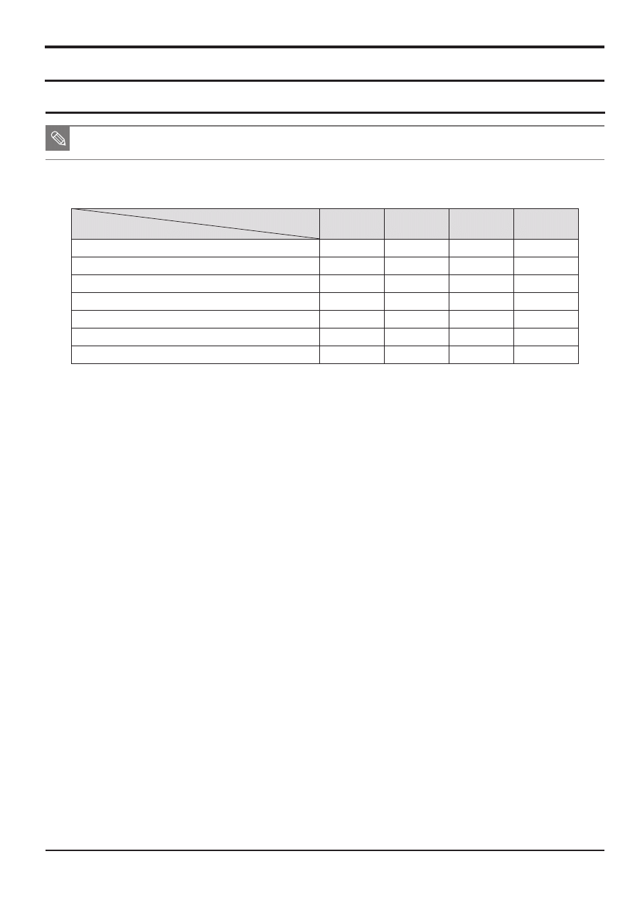
■ The following table shows the necessary adjustment item for replacing each part.
1. After replacing the electronic part, you must make adjustments for each item by referring to the following table.
<Table 5-1>
MAIN
PCB
POWER
PCB
BARREL
ASSY
CCD
ASSY
FIRMWARE UPGRADE
●
●
PUNT ADJ
●
●
●
SHUTTER CLOSE TIME, OB, LENS SHADING
●
●
●
FLASH ADJ
●
●
●
BATTERY LEVEL ADJ
●
●
BURNING TEST & CCD DEFECT CELL
●
●
●
●
SERIAL NUMBER WRITING
●
2. Adjustment equipment
- AE TESTER: AE TESTER that enables
LV 12
- Infinity Callimator for PUNT adjustment
- Gray chart (18%) for FLASH & AWB, DARK BOX)
- POWER SUPPLY: 4.2V/2A
3. Adjustment program file
Save and use the program for each adjustment item on the SD card to adjust each item.
The file name for each adjustment item is the same as
“ES70_ADJ.TXT”, “ES71_ADJ.TXT”
.
5-1 Basic guide for adjustment
Adjustment
5-2
This Document can not be used without Samsung's authorization
SAMSUNG
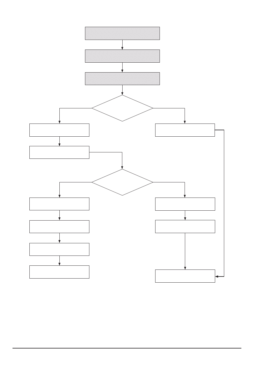
4. Operating procedure of adjustment program
Insert Flash Card (SD card) by process
Power On (Worker)
Auto process to Test Mode/Execute
adjustment script
Check process ID
Pass/No pass
Check by process
Save adjustment value to EEPROM
Display adjusted value and whether
it is OK (LCD)
Set process ID (EEPROM)
Auto Power Off or continue
with process
Record log file by process
(If necessary)
Display adjusted value and whether
it is OK (LCD)
Power Off or stand by
Display last process
ID executed normally
Save adjustment value to
EEPROM (If necessary)
No
No
Yes
Yes

SAMSUNG
This Document can not be used without Samsung’s authorization
5-3
Adjustment
5-2 OB Setting
■ Set the OB for the preview and capture respectively by defining the effective data area for the low brightness condition by
accurately judging the low signal level of the input signal.
<Adjustment method>
1. Save the applicable adjustment file to the SD card.
2. Insert the SD card with the program file saved and turn on the power of the camera.
3. Adjustment will automatically proceed.
q
Check the Preview brightness value with the shutter closed and find the OB value based on that setting.
w
Refer to the CARD WRITE information and save the Preview OB value result to the data file.
e
Refer to the EEPROM WRITE information and save the Preview adjusted value to EEPROM.
r
With the shutter closed, check the Capture brightness value to find the OB value based on that setting.
t
Refer to the CARD WRITE information and save the Capture OB value result to the data file.
y
Refer to the EEPROM WRITE information and save the Capture adjusted value to EEPROM.
u
Change the ISO and repeat the process from 4 to 6.
4. When the adjustment is completed, the camera will automatically be turned off.
<Adjustment result>
Open and check the CSV file created in the adjustment memory card.

Adjustment
5-4
This Document can not be used without Samsung's authorization
SAMSUNG
5-3 Lens Shading
■ Make adjustments to the Lens Shading to the surrounding brightness of each camera.
■ Because the surrounding brightness is lower compared to the center for each set, separately adjust each set
so that the surrounding brightness is higher.
<Adjustment method>
1. Prepare the AE TESTER.
* Luminance specification of the Light box is
12LV
.
* The Light box is located at 10mm+-1mm with the body tube open.
* The color temperature specification of the Light box is
3300K.
2. Save the applicable adjustment file to the SD card.
3. After inserting the SD card containing the program file to the camera, set the camera to the AE TESTER.
4. Adjust the LV value of the AE METER to
12
.
5. When you turn on the power of the camera, the adjustment will start automatically.
q
Adjust the Lens Shading with large lense, Zoom 0 condition.
w
Refer to the EEPROM WRITE information and write the adjustment result to EEPROM.
e
Refer to the CARD WRITE INFORMATION to write the adjustment result to the data file.
r
Set the lower and upper specification.
6. When the adjustment is completed, the camera will automatically be turned off.
<Adjustment result>
Open and check the CSV file generated from the adjustment memory card.
<Restriction>
If the capacity of CSV file is more than 30KB, clear all of the previous data and then, record
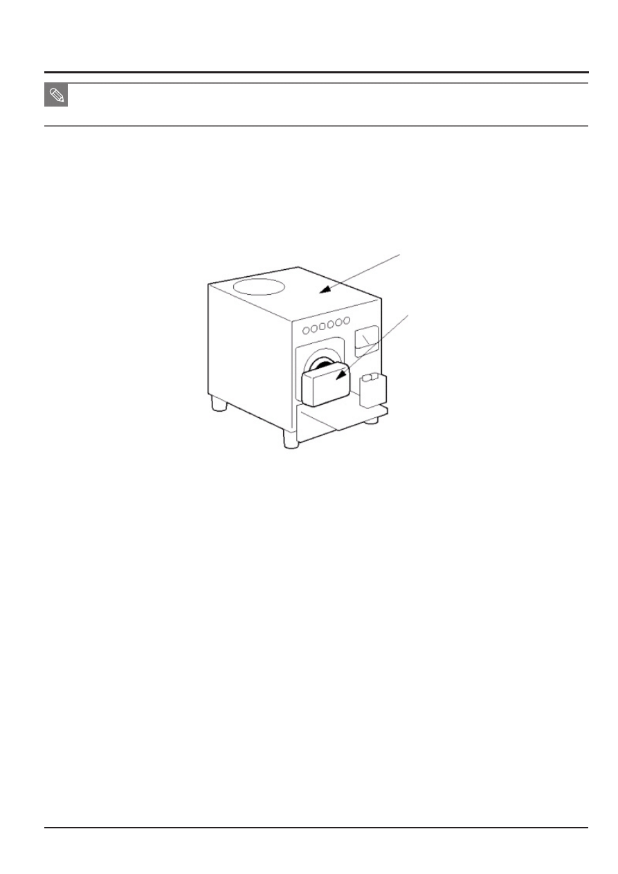
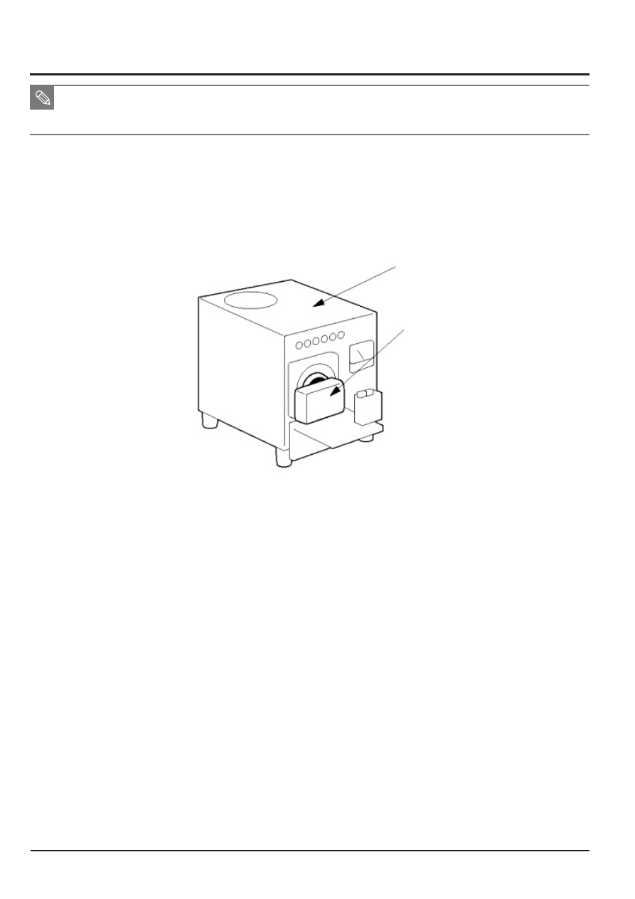
Fig. 5-1
Light source box
Camera
SAMSUNG
This Document can not be used without Samsung’s authorization
5-5
Adjustment
5-4 Shutter Close Time ADJ
■ Adjust the Close timing of the device shutter by camera.
■ Because there is a deviation of shutter closing time by each set, make adjustments by each set to reduce this deviation.
■ AWB LOW item and AWB LOW are adjusted simultaneously.
<Adjustment method>
1. Prepare the AE TESTER that can be adjusted to
LV 12
.
2. Install the camera to the AE TESTER.
* Luminance specification of the Light box is
12LV
.
* The color temperature specification of the Light box is
3300K.
3. After inserting the SD card containing the program file to the camera, turn on the power of the camera.
4. The adjustment process will automatically start.
q
Refer to the specification (Illiminance) for testing.
-Line delay and Sub delay are adjusted so that the appropriate value can be identified to the specification illuminance.
w
If the result line delay wis within the min and max range, it is OK. If it is outside of the range, process as NG.
e
Refer to the EEPROM WRITE information and write the adjustment result to EEPROM.
r
Refer to the CARD WRITE INFORMATION to write the adjustment result to the data file.
5. When the adjustment is completed, the camera will automatically be turned off.
<Adjustment result>
Open and check the CSV file generated from the adjustment memory card.
<Restriction>
If the capacity of CSV file is more than 30KB, clear all of the previous data and then, record
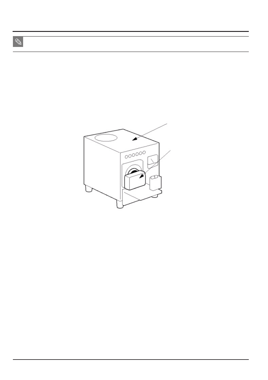
Fig. 5-2
Light source box
Camera
Adjustment
5-6
This Document can not be used without Samsung's authorization
SAMSUNG
5-5 CCD Gain ADJ
■ Because there is a deviation of CCD saturation level by each CCD, make adjustments to the basic analog gain to reduce this
deviation.
<Adjustment method>
1. Prepare the AE TESTER.
* Luminance specification of the Light box is
12LV
.
* The Light box is located at 10mm+-1mm with the body tube open.
* The color temperature specification of the Light box is
3300K.
2. Save the applicable adjustment file to the SD card.
3. After inserting the SD card containing the program file to the camera, set the camera to the AE TESTER.
Fig. 5-3
Light source box
Camera
4. Adjust the LV value of the AE METER to
12
.
5. When you turn on the power of the camera, the adjustment will start automatically.
q
Adjust the Gain.
w
Refer to the EEPROM WRITE information and write the adjustment result to EEPROM.
e
Refer to the CARD WRITE INFORMATION to write the adjustment result to the data file.
r
Set the lower and upper specification.
6. When the adjustment is completed, the camera will automatically be turned off.
<Adjustment result>
Open and check the CSV file generated from the adjustment memory card.
SAMSUNG
This Document can not be used without Samsung’s authorization
5-7
Adjustment
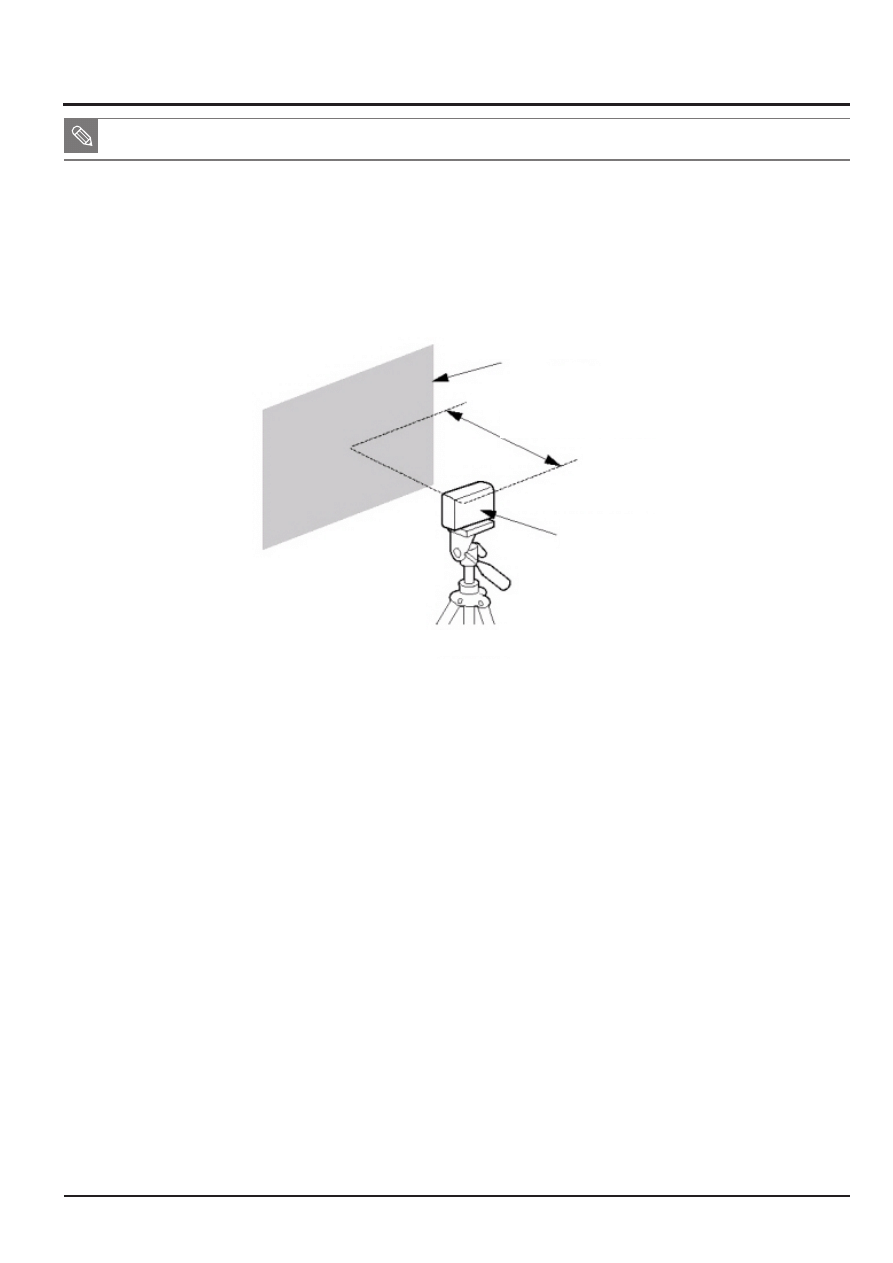
5-6 Flash ADJ
■ Set a limit to the illuminance by the Strobe light to classify the hardware defect.
■ Classify the set that deviates from the spcification by illuminating 2 times and then calculate the flash R, B gain.
<Adjustment method>
1. Attach an 18% reflective paper in the dark room where the light is blocked.
2. Set up the camera in the dark room.
3. Set the distance between the reflective paper and camera to 50cm.
4. Save the applicable adjustment file to the SD card.
5. After installing the SD card containing the program file, turn on the power of the camera.
6. The adjustment will automatically start.
q
Compare the reference illumination for 2 illuminations using the flash algorithm, and make a judgment.
w
By using the average value of the illuminance of 2 times, check the R and B gain to make Pass/No
Pass judgment.
e
Record the R and B gain to EEPROM during flash process and R, B gain success.
<Adjustment result>
Open and check the CSV file generated from the adjustment memory card.
<Restriction>
If the capacity of CSV file is more than 30KB, clear all of the previous data and then, record
Fig. 5-4
Reflective paper
50cm
Camera
Tripod
Adjustment
5-8
This Document can not be used without Samsung's authorization
SAMSUNG
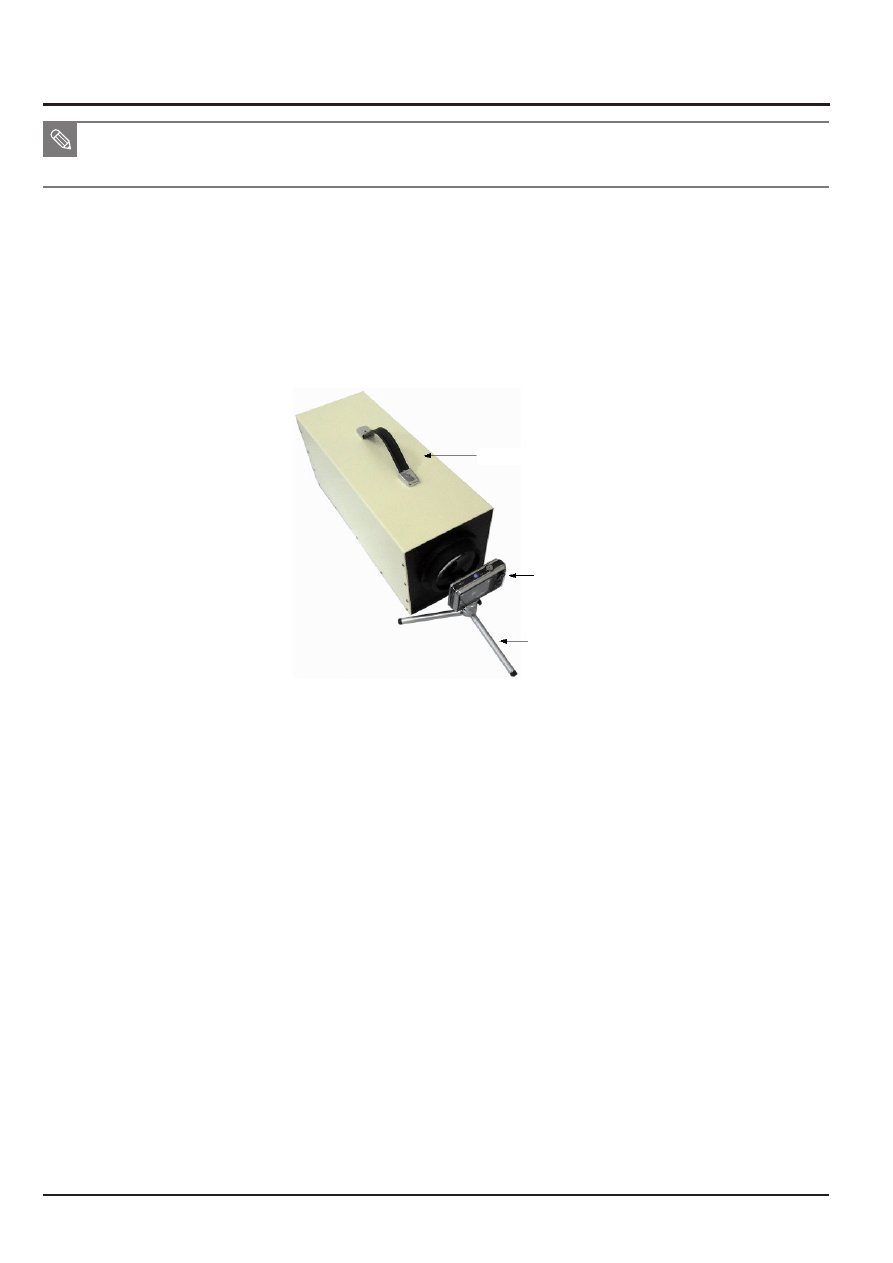
5-7 PUNT ADJ
■ Adjustment objective: After replacing the MAIN PCB and BARREL, you must decide the AF search range so that the optimal
focus can be identified by the body tube.
■ Necessary equipment: Infinity Callimator
<Adjustment method>
1. Save the adjustment file to the SD card and install it on the camera.
2. Refer to the following adjustment environment specification to adjust the focus.
1) Used specification of Infinity Callimator
- Set the illuminance specification of the Callimator to 6 LV.
- Maintain distance of less than 1cm between the end of the camera body tube to the lens surface of the Infinity Callimator.
- The camera must be fixed while the adjustment is made.
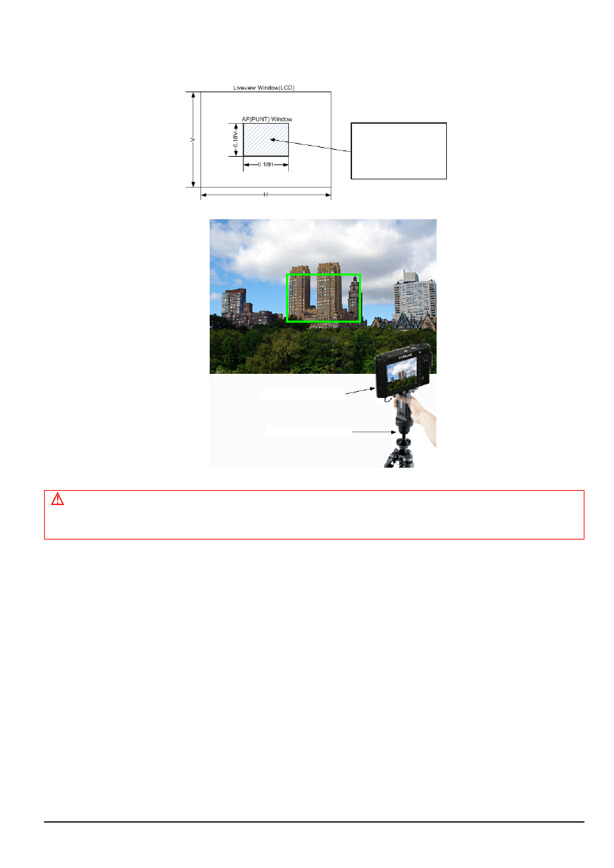
2) Used specification for infinite object
- The camera must be fixed with a tripod and leveled condition must be maintained.
- Set up the camera toward a building or object in infinite distance (more than 500m). (Do not use the chart)
- Set a cathedral, partment or object with high contrast in day environment/AF area display.
Fig. 5-5
Infinity Callimator
Camera
Tripod
SAMSUNG
This Document can not be used without Samsung’s authorization
5-9
Adjustment
3. Turn on the power of the camera.
4. The adjustment will automatically start.
<Adjustment result>
Open and check the CSV file generated from the adjustment memory card.
Fig. 5-6
When you view the
LCD, the object must
be within 20% size
from the center.
Camera
Tripod
Caution
■ For the object, exclude full glass buildings or objects with low contrast, and this cannot be adjusted for night time.
For the adjustment in these environments, AF may not be accurate when shooting Tele or Macro.
Adjustment
5-10
This Document can not be used without Samsung's authorization
SAMSUNG
5-8 B/T Level ADJ
<Adjustment method>
1. Prepare the POWER SUPPLY.
2. Use the battery jig to connec the POWER SUPPLY to the camera.
3. Set to voltage of 3V.
4. Save the applicable adjustment file to the SD card.
5. After inserting the SD card containing the program file, turn on the power of the camera.
6. The adjustment will automatically start. This is not displayed on the screen.
q
Execute A/D Conversion of the current power supply condition.
w
After the A/D conversion value of the current power supply voltage is measured, check whether it falls
within the error range. (Idle mode)
[Min A/D conversion value] <= [A/D conversion value of power supply voltage] <= [Max A/D conversion value]
e
Refer to the warning and prohibition label to execute the check.
r
Refer to the EEPROM WRITE information and write the adjustment result to EEPROM.
t
Refer to the CARD WRITE INFORMATION to write the adjustment result to the data file.
7. When the adjustment is completed, the camera will automatically be turned off.
■ Adjust the level of reference voltage to display the battery condition by each camera.
5-9 CCD Defect ADJ
<Adjustment method>
1. Save the applicable adjustment file to the SD card.
2. After inserting the SD card containing the program file, turn on the power of the camera.
3. The adjustment will automatically start.
q
Check the set reference level, exposure time and loop, and execute the Defective Pixel calibration.
w
Refer to the specification (Maximum number of defective cells) and execute the check.
e
Refer to the CARD WRITE information to write the number of defective cells to the data file.
4. When the adjustment is completed, the camera will automatically be turned off.
<Adjustment result>
Open and check the CSV file generated from the adjustment memory card.
■ Calibrate the Defective pixel of CCD for each camera.
SAMSUNG
This Document can not be used without Samsung’s authorization
5-11
Adjustment
5-10 BackLash ADJ
<Adjustment method>
1. Save the applicable adjustment file to the SD card.
2. After inserting the SD card containing the program file, turn on the power of the camera.
3. The adjustment will automatically start.
q
Close the body tube.
w
After moving the body tube to Tele, calculate the error of PI count after it comes to Close.
e
Repeat as many times as the count as above and obtain PI Count error sample to calculate the average.
r
Judge whether the obtained average falls within the range of Max_backLash Range.
t
Prepare the log file and move to Wide.
4. When the adjustment is completed, the camera will automatically be turned off.
<Adjustment result>
Open and check the CSV file generated from the adjustment memory card.
■ Calibrate the error that occurs when the direction of the lens change by each camera.
5-11 Burning ADJ
<Adjustment method>
1. Save the Burning program to the SD card.
2. After inserting the SD card containing the program file, turn on the power of the camera.
3. The camera will automatically operate in the order of the set function.
q
Execute the Booting operation.
w
Check the set operation cycle repetition, number of functional tests, function
1, function 2, ..., and execute the operation for each function.
* When the cycle of one function starts, the number of remaining cycles and completed function code are saved in
EEPROM. (This is to classify the defective operation)
EEPROM address
- Davinci_125UW : 744 burn count ) , 746( Cycle in progress )
e
When the Burning process is completed, the power will automatically be turned off.
■ Repeatly operate various functions of the camera to detect sets with H/W or S/W defects.
Adjustment
5-12
This Document can not be used without Samsung's authorization
SAMSUNG
5-12 IRIS adjustment
■ Adjust the close time of the equipment shutter of each camera.
■ When using the multi-layer iris, there might be deviation in the aperture of each layer. Therefore, try to reduce the deviation of the
aperture of each layer by adjusting each aperture set.
<Adjustment method>
1. Prepare AE TESTER which is adjusted by
LV 12
.
2. Install AE TESTER on camera.
* Brightness of the light box is
12 LV
.
* The color temperature of the light box is
3200K.
3. Install SD card with program files and then, turn the camera on.
4. Adjustment is made automatically.
q
Set an ideal AV value for each iris layer.
w
Set the exposure time and the gain value and change the iris layer and measure the preview G value for each iris layer.
e
2 conditions is satisfied, if the preview G value for the big iris layer is bigger than that for the small one. If not, NG.
r
Determine if A V value calculated for each iris is within the iris adjustment range. If it is, Preview G value is satisfied. If not, NG.
-If the 2 conditions are satisfied, set the iris value to be actually used using the difference between the AV values of the iris
layers calculated.
t
Refer to EEPROM WRITE information to write the adjusted value on EEPROM.
y
Refer to CARD WRITE information to write the adjusted value on a data file.
5. Once the adjustment is completed, the camera is automatically off.
<Adjustment result>
Open a CSV file created on the adjustment memory card to check the result.
<Restriction>
If the capacity of CSV file is more than 30KB, clear all of the previous data and then, record
Fig. 5-7
Light source box
Camera

SAMSUNG
This Document can not be used without Samsung’s authorization
5-13
Adjustment
5-13 OIS Centering adjustment
<Adjustment method>
1. Save OIS .hex file and script file on SD card.
2. Install SD card with a program file and then, turn the camera on.
3. Adjustment is made automatically.
OIS module will be operated left/right/up/down 2-3 times.
4. When the adjustment is completed, the camera will be off automatically.
<Adjustment result>
Open the CSV file created on the adjustment memory card to check the result.
■ Process to check if OIS performs well or not.

Adjustment
5-14
This Document can not be used without Samsung's authorization
SAMSUNG
5-14 Serial number writing process
■ Save S/N on the label of the camera in non-volatile memory due to the illegal distribution of DSC.
■ When checking the version, check S/N to see if the camera is original or illegally distributed one.
<Caution when repairing>
Copy the S/N writing script, transfered from scanned data, to camera through USB
Then, S/N writing process will be done, automatically, after disconnected USB cable. S/N writing script file has de-
leted automatically, after finished the S/N writing process same with RTC test script.
<Process result>
When checking the version (Press SHUTTER Button + Zoom Button to turn on), S/N appears on the screen.
Document Outline
Wyszukiwarka
Podobne podstrony:
06 Alignment & Adjustment
Alignment & Adjustment
Alignmaster tutorial by PAV1007 Nieznany
Ćwiczenie 1 Quick Alignment and Carriageways
75 WHEEL ALIGNMENT THEORY OPERATION
alignment(4)
Front End Alignment Basics
Checking Table Saw Blade Alignment
Adjustable Plant Shelves
Adjustacjaetc program
Front End Alignment Tests For
aem billet adjustable fuel pressure regulators
M32b Wheel Alignment
05 Structures and Alignment
74 WHEEL ALIGNMENT SPECIFICATIONS & PROCEDURES
ARTICLE PBRAKE ADJUSTMENT EXTERNAL
Znaki adjustacyjne i korektorskie(1)
Adjustment Instruction M13 M113
0560 Adjusting valve clearance
więcej podobnych podstron