
Initial Print Date: 3/06
Table of Contents
Subject
Page
Steering Ratio . . . . . . . . . . . . . . . . . . . . . . . . . . . . . . . . . . . . . . . . . . . . . . . . . .5
Steering System Types . . . . . . . . . . . . . . . . . . . . . . . . . . . . . . . . . . . . . . . . . .7
Recirculating-ball Steering . . . . . . . . . . . . . . . . . . . . . . . . . . . . . . . . . . .7
Rack-and-pinion Steering . . . . . . . . . . . . . . . . . . . . . . . . . . . . . . . . . . . . .8
Advantages of Active Steering . . . . . . . . . . . . . . . . . . . . . . . . . . . . . . . . . .10
Mechanical System Overview . . . . . . . . . . . . . . . . . . . . . . . . . . . . . . . . . . .11
Bus System Overview (up to 9/2005) . . . . . . . . . . . . . . . . . . . . . . . . . . . .12
Electrical System Overview (IPO) up to 9/2005 . . . . . . . . . . . . . . . . . . .14
Electrical System Overview (IPO) from 9/2005 . . . . . . . . . . . . . . . . . . . .16
Electrical System Overview (IPO) E9X Vehicles from SOP . . . . . . . . . .18
Electronically Controlled Orifice (ECO) . . . . . . . . . . . . . . . . . . . . . . . .20
Power Steering Fluid Cooler . . . . . . . . . . . . . . . . . . . . . . . . . . . . . . . . . . . .23
Steering Rack and Pinion Unit . . . . . . . . . . . . . . . . . . . . . . . . . . . . . . . . . .24
Actuator Motor Position Sensor . . . . . . . . . . . . . . . . . . . . . . . . . . . . . .31
Magnetoresistive Element . . . . . . . . . . . . . . . . . . . . . . . . . . . . . . . . . . .33
Sensor Communication . . . . . . . . . . . . . . . . . . . . . . . . . . . . . . . . . . .34
Steering Angle Sensor (from 9/05 and E90) . . . . . . . . . . . . . . . . . . . .36
Active Steering
Revision Date:

Subject
Page
Detecting Steering Angle . . . . . . . . . . . . . . . . . . . . . . . . . . . . . . . . . . . .37
Relative Steering Angle . . . . . . . . . . . . . . . . . . . . . . . . . . . . . . . . . . . . . .38
Active Steering Control Module . . . . . . . . . . . . . . . . . . . . . . . . . . . . . . . . .41
Safety Monitoring Functions . . . . . . . . . . . . . . . . . . . . . . . . . . . . . .42
Changes from 9/2005 . . . . . . . . . . . . . . . . . . . . . . . . . . . . . . . . . . . . . . .42
Safety and Gateway Module (SGM) . . . . . . . . . . . . . . . . . . . . . . . . . . . . . .43
Body and Gateway Module (KGM) . . . . . . . . . . . . . . . . . . . . . . . . . . . . . .43
Junction Box (E9X) . . . . . . . . . . . . . . . . . . . . . . . . . . . . . . . . . . . . . . . . . . . .44
DSC Control Module . . . . . . . . . . . . . . . . . . . . . . . . . . . . . . . . . . . . . . . . . .44
ECM (DME) . . . . . . . . . . . . . . . . . . . . . . . . . . . . . . . . . . . . . . . . . . . . . . . . . .44
CAS: Car Access System . . . . . . . . . . . . . . . . . . . . . . . . . . . . . . . . . . . . . .44
Warning Lights and Check Control . . . . . . . . . . . . . . . . . . . . . . . . . . . . . .45
Active Steering Functions . . . . . . . . . . . . . . . . . . . . . . . . . . . . . . . . . . . .47
Steering Assistance . . . . . . . . . . . . . . . . . . . . . . . . . . . . . . . . . . . . . . . . . . .47
Variable Steering-gear Ratio . . . . . . . . . . . . . . . . . . . . . . . . . . . . . . . . . . . .49
Yaw-rate Control . . . . . . . . . . . . . . . . . . . . . . . . . . . . . . . . . . . . . . . . . . . . . .51
Yaw-moment Compensation (E90/E91) . . . . . . . . . . . . . . . . . . . . . . .51
AFS Initialization/Adjustment . . . . . . . . . . . . . . . . . . . . . . . . . . . . . . . . . . . .56
Wheel Alignment . . . . . . . . . . . . . . . . . . . . . . . . . . . . . . . . . . . . . . . . . . . . . .57

Active Steering
Model: 5 and 6 Series (E6X), 3 Series (E9X)
Production: From Start of Production
3
Active Steering
After completion of this module you will be able to:
• Understand Steering Ratio
• Understand the Concept of Active Steering
• Identify and Locate Active Steering Components
• Diagnose Concerns on Active Steering Systems
• Perform Alignments on Vehicles Equipped wit Active Steering
4
Active Steering
At BMW, steering systems have become an increasingly complex topic. This training
module is designed to review basic steering technology and to introduce the latest
Active Steering technology.
You will be able to familiarize yourself with the most important steering systems at BMW
Group and also find out how they are put together and how they work. Afterwards, you
will understand their construction and interaction, which will mean that you will be
equipped with all the knowledge you need for successful troubleshooting of steering
system faults.
These theoretical and practical exercises will enable you to better understand Active
Steering systems, which will aid in service and diagnostic concerns.
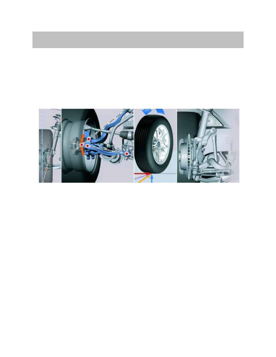
A steering system must be able to convert a turning motion input by the driver at the
steering wheel into a change of steering angle at the steered wheels on the vehicle. This
is the essential requirement of a steering system irrespective of whether it is a simple,
conventional steering system or the latest modern BMW Group steering system.
Steering systems must have the following characteristics:
• The construction of the steering gearbox in each case must enable the vehicle to
respond to the slightest steering adjustments.
• When the steering wheel is released, the wheels must return to the center position
(straight-ahead travel).
• The steering geometry must follow the Ackermann rule, i.e. when the left and right
wheels are at full lock, the extension of the wheel axes must intersect the extension
of the rear axle.
• The steering system must compensate for uneven road surfaces while ensuring
that the driver remains in control.
• To achieve the best possible handling, the steering system must have a low steer-
ing ratio (i.e. number of steering wheel turns from lock to lock).
Introduction
Steering Ratio
In order to better understand basic steering theory it is necessary to understand steering
ratio. Steering ratio is the relationship between the number of turns of the steering
wheel in comparison to the amount of steering angle change that occurs at the front
wheels.
For example, if the steering wheel is turned through 360 degrees of rotation and the
front wheels turn through an arc of 20 degrees, the steering ratio is therefore 18:1. In
other words, it takes 18 degrees of steering wheel rotation to achieve 1 degree of steer-
ing movement at the front wheels.
A “high” steering ratio (which is less direct) such as 18:1 dictates that a large amount of
steering input is required to steer the vehicle through turns. A ratio of 18:1 is good for
high road speeds. This is due to the fact that there would be no excessive movement of
the front wheels when making lane changes. Therefore, a numerically “high-ratio” is
optimal for higher road speeds.
In contrast, when driving a lower speeds such as parking, a “low-ratio” steering , such as
10:1, would be better. Less input at the steering wheel would aid parking and be more
comfortable for the driver. Also, low speed maneuvers such as low speed corners or
avoiding road debris would be greatly improved. A “low-ratio” is also referred to as a
“more direct” steering ratio.
5
Active Steering
Steering Fundamentals
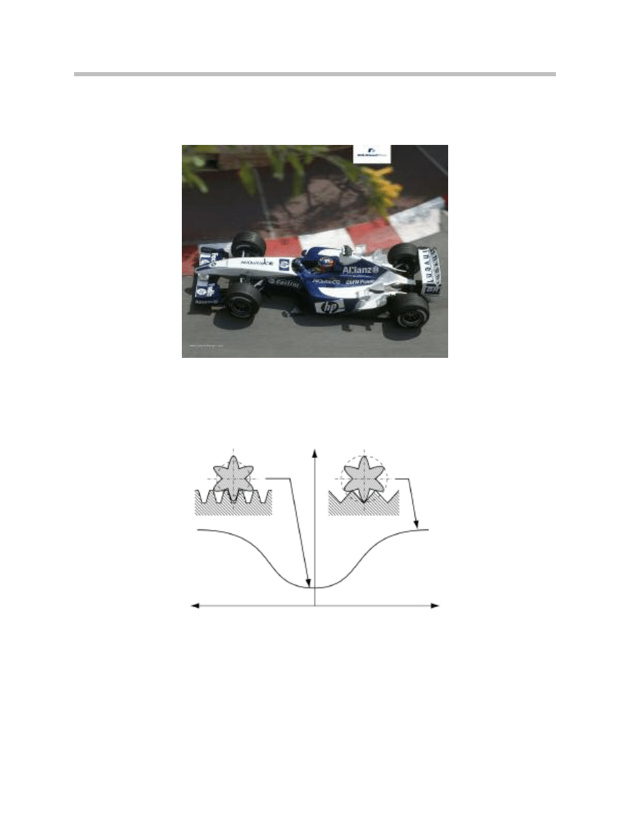
Vehicles designed for racing, such as Formula 1 cars, use a “low-ratio” steering setup.
These types of vehicles would not benefit from a higher steering ratio. Tight, high-speed
turns require a “quick” response from the steering system.
In order to achieve the “best of both worlds”, some BMW vehicles have been equipped
with a “variable-ratio” rack and pinion steering system. This is a purely mechanical
system which uses a rack and pinion unit that has teeth of different “pitch” throughout
the length of the rack gear.
The teeth on the outer ends of the rack gear are more tightly spaced and the teeth in the
center of the rack gear are more loosely spaced. This gives the effect of a “high-ratio”
(less direct) when driving on the highway. At low speeds when more turning angle is
required, the teeth on the outer end of the rack allow for a “lower-ratio” (more direct)
steering which is more responsive during the required maneuvers.
6
Active Steering
7
Active Steering
Steering System Types
As far as steering systems are concerned, they are two basic types of steering mecha-
nisms used on BMW Group vehicles. These include the following:
• Recirculating-ball steering - This is also known as “ball and nut” or the more
common term being “steering box”. This arrangement has been in use on early
models usually the 5 and 7 series. The last vehicles in production to use this type of
steering arrangement was the E38 and E39. The 8-cylinder E39 (540i) utilized the
steering box, while the 6-cylinder E39 (528i/530i etc.) use a “rack and pinion”
steering design.
• Rack and Pinion steering - The more common steering gear design is the rack and
pinion which is more versatile and lighter in weight. This is used on all current
BMW models.
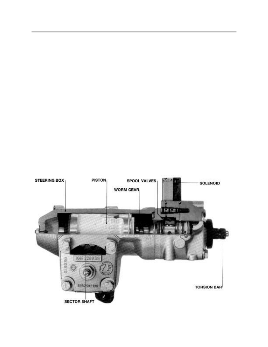
Recirculating-ball Steering
A low friction endless row of balls transmits forces between the steering worm and steer-
ing nut. The steering nut exerts a force on the steering shaft via gear teeth. A variable
ratio is also possible with this steering gear.
An extensive and wide-ranging development history lies behind the modern steering
systems used nowadays incorporating power steering assistance.
8
Active Steering
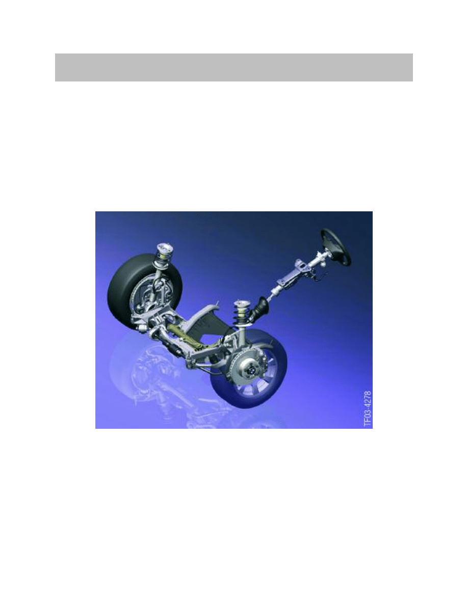
Rack-and-pinion Steering
Rack-and-pinion steering essentially consists of a pinion and toothed rack. The steering
ratio is determined by the ratio between the number of pinion revolutions (steering wheel
turn) and the rack travel. The steering ratio varies with the rack travel and corresponding
gearing of the rack. Steering corrections and operating forces are dealt with by this sys-
tem.
As discussed previously, there is a need to enhance existing steering technology.
Overall, the best way to increase agility, convenience and safety is by the use of Active
Steering. The new Active Steering system was first introduced as an option on the E60
and is currently available on the 5 and 6 Series (E6X) as well as the new 3 Series (E9X).
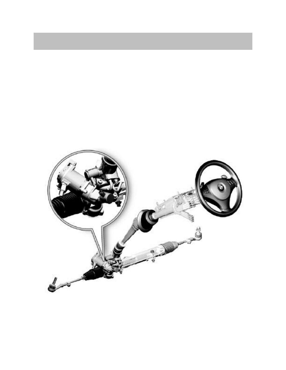
Active Steering employs a combination of a conventional “Rack and Pinion” steering
system with a planetary gear system. The planetary gear system is actuated via a
3-phase DC motor which is controlled an electronic control module.
The Active Steering system allows a steering ratio which is fully variable based on road
speed and environmental conditions such as yaw and lateral acceleration etc. In con-
trast to a variable ratio rack and pinion, which is purely mechanical, the AFS system is
capable of manipulating the steering ratio from a more direct ratio (10:1) to a less direct
ratio (20:1).
Note: Since the introduction of Active Front Steering (AFS), the terminology
has been changed to Active Steering (AS). The German term for Active
Steering is “Activ Lenkung” (AL). Any of the above terms may be used
in this training module.
9
Active Steering
Active Steering

10
Active Steering
Advantages of Active Steering
In addition to the power assisted torque provided by the power steering, the Active
Steering System provides a variable steering ratio to assist the driver. During this process
and depending on the vehicle speed, an electric motor drives a worm gear which is
meshed to a member of a planetary gearbox. This gearbox is capable of effecting the
steering ratio. This means that, depending on the driving situation, the steering system
generates an additional (or reduced) steering angle for the front wheels by changing the
steering ratio.
The active steering system is networked with the DSC driving stability program and is
capable of intervention, by correcting the steering angle, at the first sign of instability.
This means that active steering reduces DSC interventions in the lower response range
thus providing optimum control comfort.
Increased Agility
Due to the direct transmission ratio, the vehicle is perceived as having a greater agility and
handling performance up into the medium driving speed range (approximately 62 mph or
100 km/h).
The driver also has far greater control accident avoidance , for example - this combined
with considerably enhanced steering precision and reduced steering effort. Direct
contact with the road via the steering wheel is maintained throughout.
Increased Convenience
Some BMW models require more than 3 full steering-wheel turns to achieve a full wheel
lock from the far left over to far right. Active Steering reduces this at low speeds to less
than 2 steering-wheel turns from lock to lock.
The benefit is less steering effort required when turning in city traffic or maneuvering in
narrow parking spaces. On twisting roads in mountainous regions, for example, the
reduced steering angle also ensures that hands always remain in the optimum position
on the steering wheel, which means that crossing of hands, or even arms in some cases,
is no longer necessary. The multifunction buttons on the steering wheel or the gearshift
paddles for the SMG always remain conveniently within reach in all road situations.
Increased Active Driving Safety
The situation at high speeds is somewhat different in that a more indirect transmission
ratio when traveling at high speed has a dampening effect on sudden (or excessive)
steering input. Any abrupt steering input is countered by the Active steering system and
serves to stabilize any yaw reactions of the vehicle.
Yaw motion occurs for example when changing lanes, when swerving or when a load
change occurs during cornering. Active steering intervenes electronically at all speeds
without the driver being aware of this. The electronic stability program - dynamic stability
control (DSC) - therefore does not need to intervene as frequently or as powerfully.
11
Active Steering
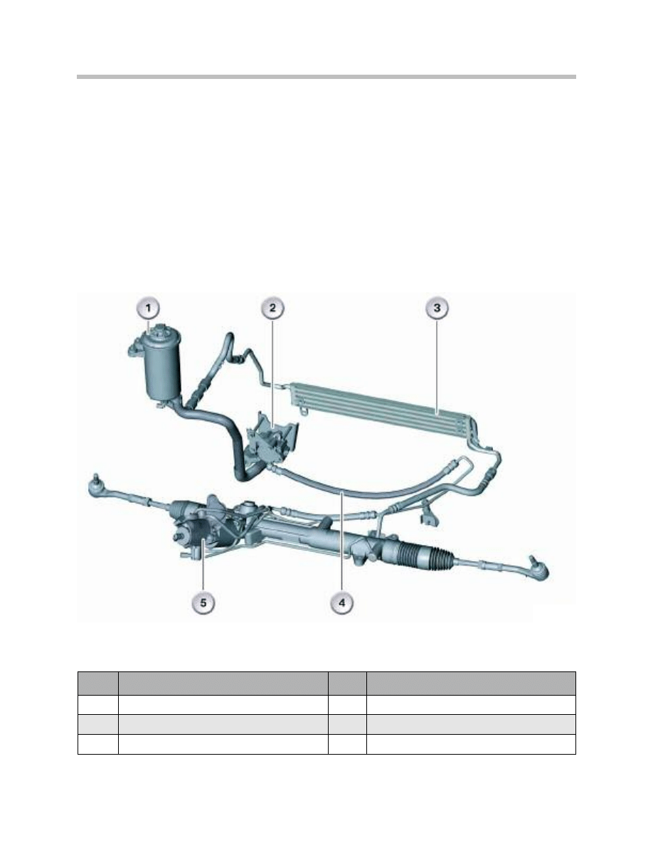
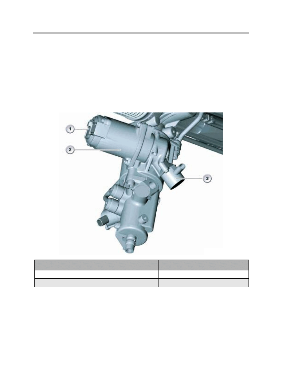
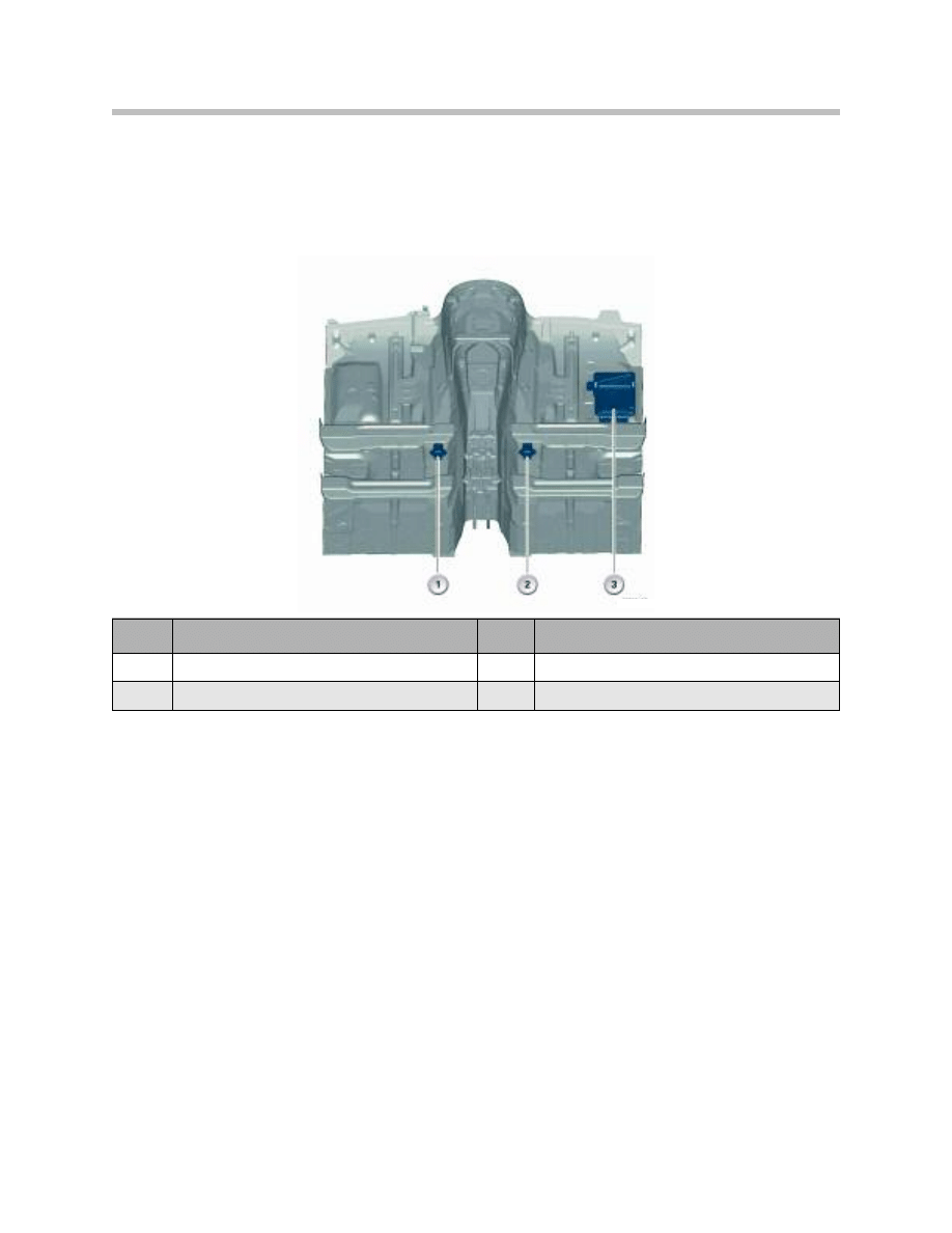
Mechanical System Overview
The Active Steering System is based on a conventional rack and pinion style steering
design. The major difference between the active steering system and a conventional
rack and pinion system is steering gear.
The active steering system uses a conventional rack and pinion which has been modified
by the addition of an actuating unit between the steering input pinion and the rack gear.
The major mechanical components of active steering system include the following
components:
Index
Explanation
Index
Explanation
1
Hydraulic oil reservoir
4
Hydraulic hose
2
Hydraulic pump with ECO valve
5
Steering gear with actuating unit
3
Power steering fluid cooler
12
Active Steering
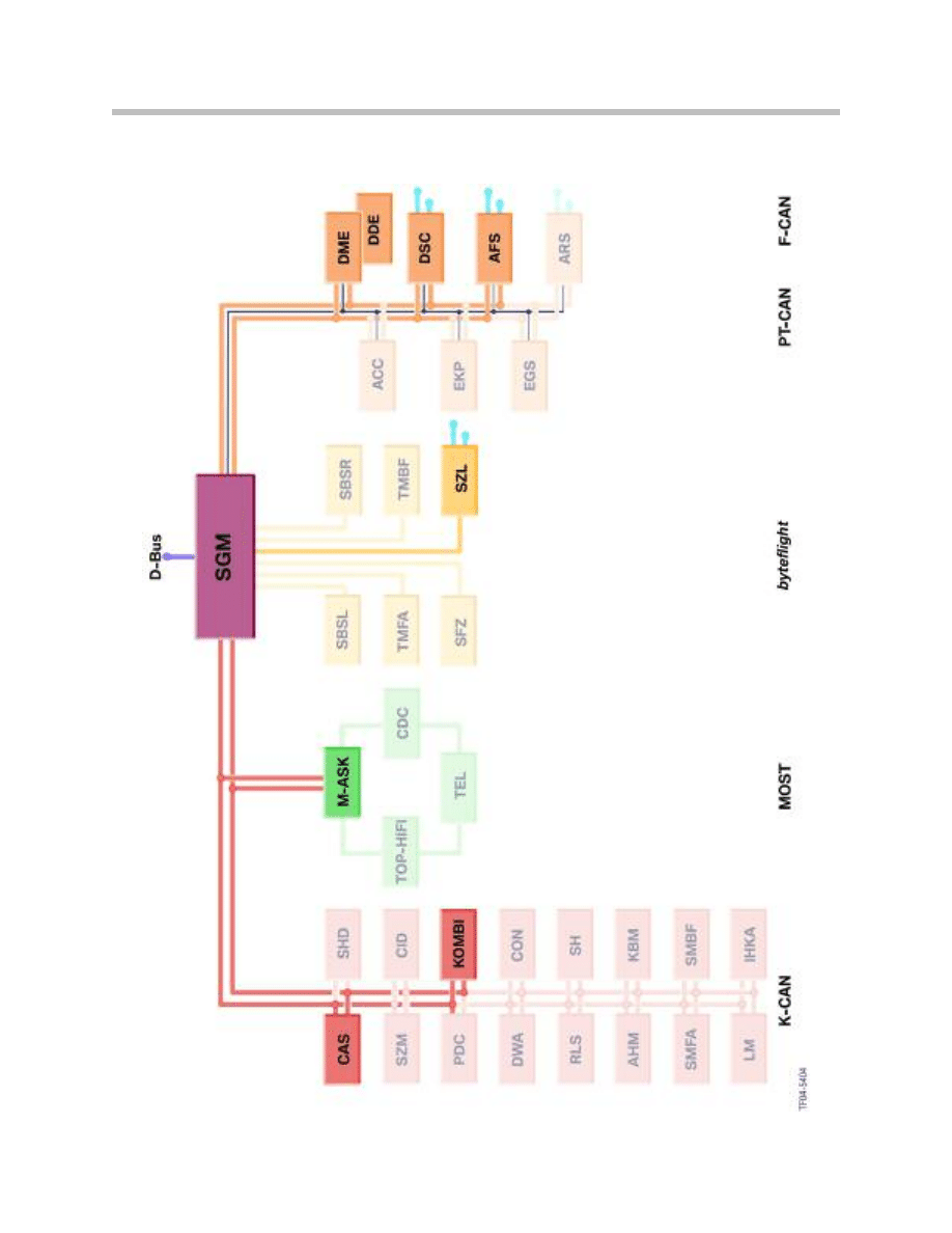
Bus System Overview (up to 9/2005)

13
Active Steering
NOTES
PAGE
14
Active Steering
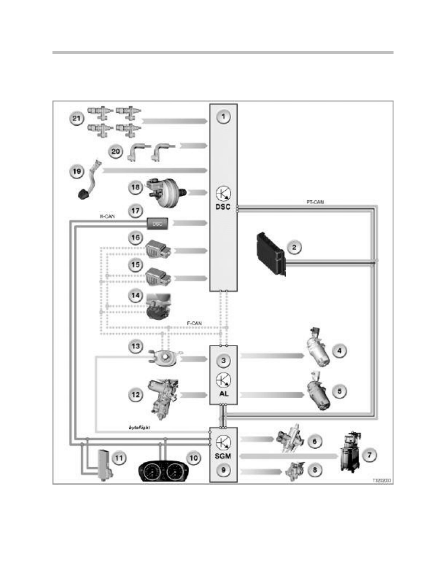
Electrical System Overview (IPO) up to 9/2005

15
Active Steering
Legend for Overview
Index
Explanation
Index
Explanation
1
Dynamic Stability Control Module
13
Steering angle sensor (in SZL)
2
Engine Control Module (DME)
14
Total (cumulative ) steering angle sensor
3
Active Steering Control Module (AL,AS,AFS)
15
DSC sensor 2
4
Electro-magnetic lock
16
DSC sensor 1
5
Actuator motor
17
DSC switch (in SZM)
6
Servotronic valve
18
Brake fluid level switch
7
Diagnosis (DISplus/GT-1)
19
Brake light switch
8
Electronically Controlled Orifice (ECO)
20
Brake pad wear sensors
9
Safety and Gateway Module (SGM)
21
Wheel speed sensors
10
Instrument cluster
F-CAN
Chassis Controller Area Network
11
Car Access System (CAS)
K-CAN
Chassis Controller Area Network
12
Actuator motor position sensor
PT-CAN
Chassis Controller Area Network
16
Active Steering
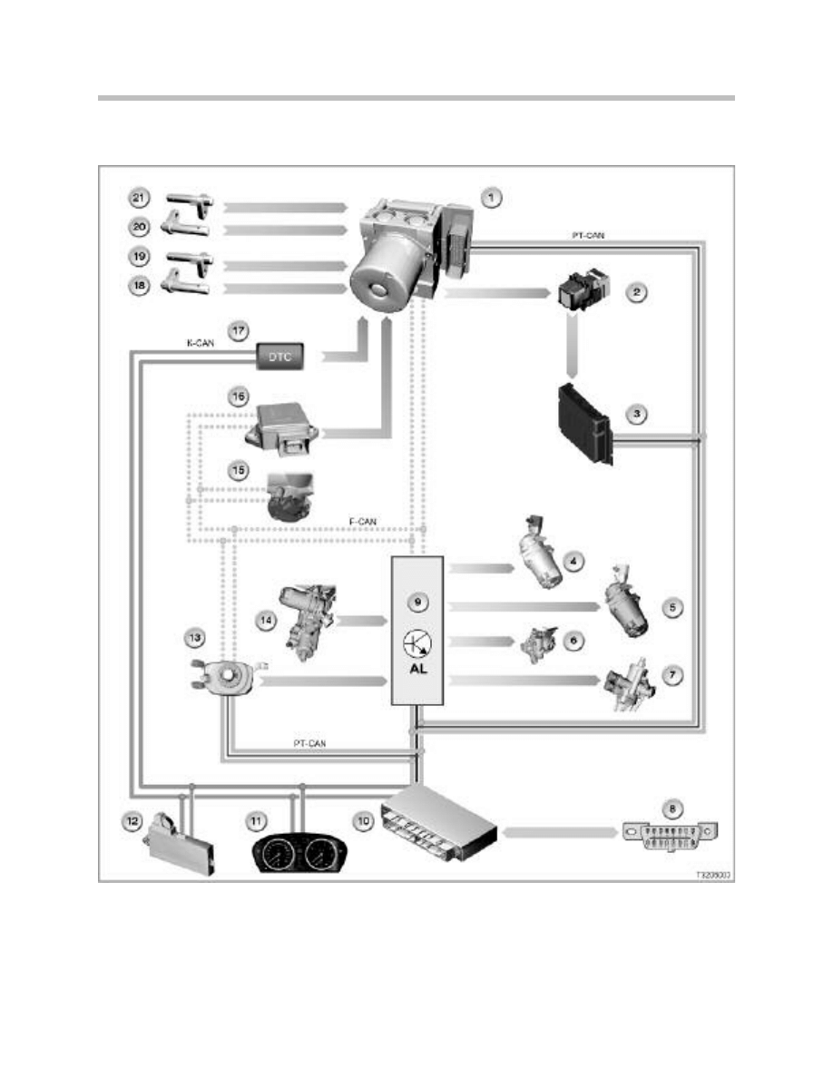
Electrical System Overview (IPO) from 9/2005

17
Active Steering
Legend for Overview
Index
Explanation
Index
Explanation
1
Dynamic Stability Control Module
13
Steering angle sensor (in SZL)
2
Brake light switch
14
Actuator motor position sensor
3
Engine Control Module (DME)
15
Total (cumulative ) steering angle sensor
4
Electro-magnetic lock
16
DSC sensor 1
5
Actuator motor
17
DSC switch (in SZM)
6
Electronically Controlled Orifice (ECO)
18
Wheel speed sensor
7
Servotronic valve
19
Wheel speed sensor
8
Diagnosis (DISplus/GT-1)
20
Wheel speed sensor
9
Active Steering Control Module (AL,AS,AFS)
21
Wheel speed sensor
10
Body and Gateway Module (KGM)
F-CAN
Chassis Controller Area Network
11
Instrument cluster
K-CAN
Chassis Controller Area Network
12
Car Access System (CAS)
PT-CAN
Chassis Controller Area Network
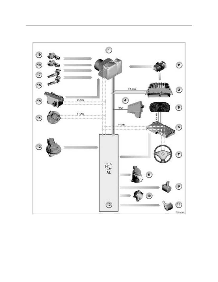
Electrical System Overview (IPO) E9X Vehicles from SOP
18
Active Steering

Legend for Overview
19
Active Steering
Index
Explanation
Index
Explanation
1
Dynamic Stability Control Module
12
Active Steering Control Module (AL,AS,AFS)
2
Brake light switch
13
Actuator motor position sensor
3
Engine Control Module (DME)
14
Total (cumulative ) steering angle sensor
4
Car Access System (CAS)
15
DSC Sensor
5
Instrument cluster
16
Wheel speed sensor
6
Junction Box Electronics (JBE)
17
Wheel speed sensor
7
Steering angle sensor (in SZL)
18
Wheel speed sensor
8
Actuator motor
19
Wheel speed sensor
9
Electro-magnetic lock
F-CAN
Chassis Controller Area Network
10
Electronically Controlled Orifice (ECO)
K-CAN
Body Controller Area Network
11
Servotronic valve
PT-CAN
Powertrain Controller Area Network
Power Steering Pump
The power steering pump is a vane-type which uses an electrically regulated valve for
adjusting the volumetric flow of the hydraulic fluid. Due to the fact that the active steer-
ing system is capable of providing the required wheel angle at a faster rate that conven-
tional steering, a high volume pump is needed. However, a conventional high volume
pump would be impractical due to the external size requirements. Also, the pump would
cause increased fuel consumption and emissions.
As an alternative, the pump is designed as a compact unit with a variable flow rate which
is controlled electronically by the active steering system.
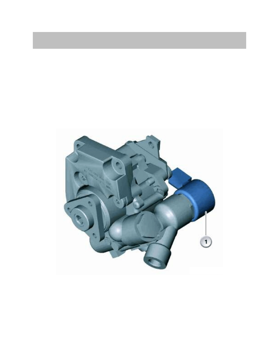
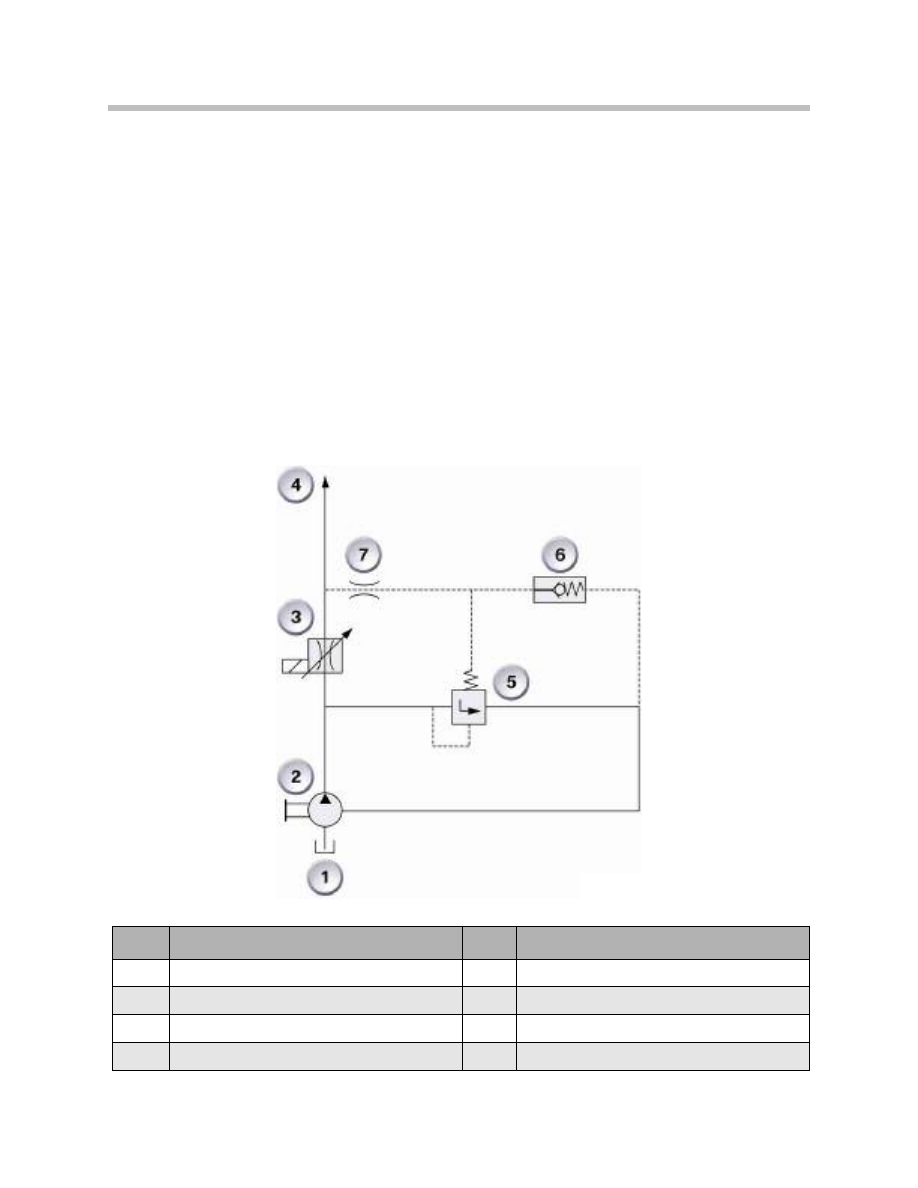
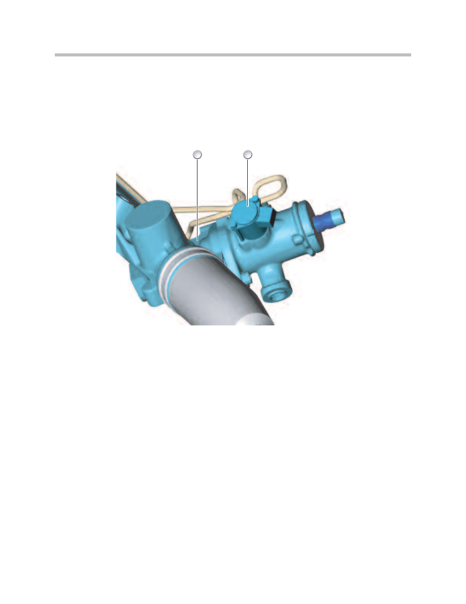
Electronically Controlled Orifice (ECO)
In order to allow electronic control of the power steering pump, an electronically
controlled orifice (ECO) is installed in the power steering pump housing.
The valve, which is only installed on vehicles equipped with AFS, provides additional
flow from the power steering pump when needed. This usually occurs at low speeds
when a more direct steering ratio is needed.
System Components
20
Active Steering
1. ECO Valve
This additional flow allows increased angular velocity of the front wheels when steering at
low speeds during parking or low speed maneuvers.
Depending on the model and production date, the ECO valve is controlled by the
following modules:
• The SGM on 5 and 6 series vehicles up to 9/2005
• The Active Steering control module on 5 and 6 Series (from 9/2005) and
3 series (E9X)
When the ECO valve is supplied with maximum current, the valve is fully open and allows
the power steering pump to deliver the maximum flow rate of 15 liters per minute
(depending on engine speed).
When the valve is not supplied with current, the valve is closed and restricts the power
steering flow to approximately 7 liters per minute for power steering assistance.
21
Active Steering
Index
Explanation
Index
Explanation
1
Hydraulic reservoir
5
Pressure regulating valve
2
Hydraulic pump
6
Pressure limiting valve
3
ECO valve
7
Damping orifice
4
to power assisted rack and pinion steering
Servotronic
The Servotronic controls the degree of assistance provided by the hydraulic steering as a
function of the vehicle's speed. The flow of hydraulic fluid is restricted to a greater or
lesser extent depending on how the Servotronic valve is actuated. Restriction of the flow
depends on the current actuating the Servotronic valve.
E60, E61, E63, E64 up to 09/2005
The safety and gateway module (SGM) actuates the Servotronic valve.
In a vehicle fitted with Active Steering, the AL control module determines the nominal
current for the Servotronic valve. In the event of the AL control module failing, the SGM
assumes the default value of the nominal current.
E90, E91 and E60, E61, E63, E64 from 09/2005
The Servotronic valve is actuated directly by the AL control module.
The signals and messages required for the Servotronic are as follows:
• Road speed from the DSC control module via the PT-CAN
• Status of the engine from the DME control module via the PT-CAN
• Terminal status of the CAS control module via the K-CAN
The Servotronic valve is actuated only when terminal 15 is ON and the engine is running.
When the speed signal is present the default value of the nominal current is taken from
the characteristic map.
22
Active Steering
T
F
0
4
-
5
5
2
5
2
1
1. Steering Rack
2. Servotronic Valve
The current supply to the Servotronic valve is interrupted by the faults listed below. Under
these circumstances, steering assistance is limited to a minimum:
• Speed signal from the DSC control module incorrect or no speed signal
• Terminal status from CAS control module via K-CAN incorrect or missing
• Line fault to the Servotronic valve (exception: short-circuit to positive)
In the event of a short-circuit to positive, the entire on-board network voltage is applied to
the Servotronic valve. This means that the Servotronic valve is fully actuated. Under these
circumstances steering assistance is increased to maximum.
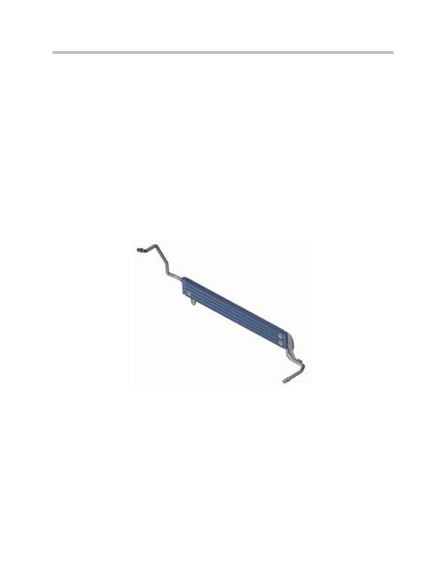
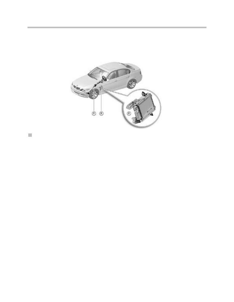
Power Steering Fluid Cooler
Due to the increased fluid volume and flow rate of the active steering system, a cooler
has been added to the system. The cooler, which has a 4 tube and fin design, provides
additional cooling capacity over a conventional cooler design. The cooler is located at the
front of the AC condenser.
23
Active Steering
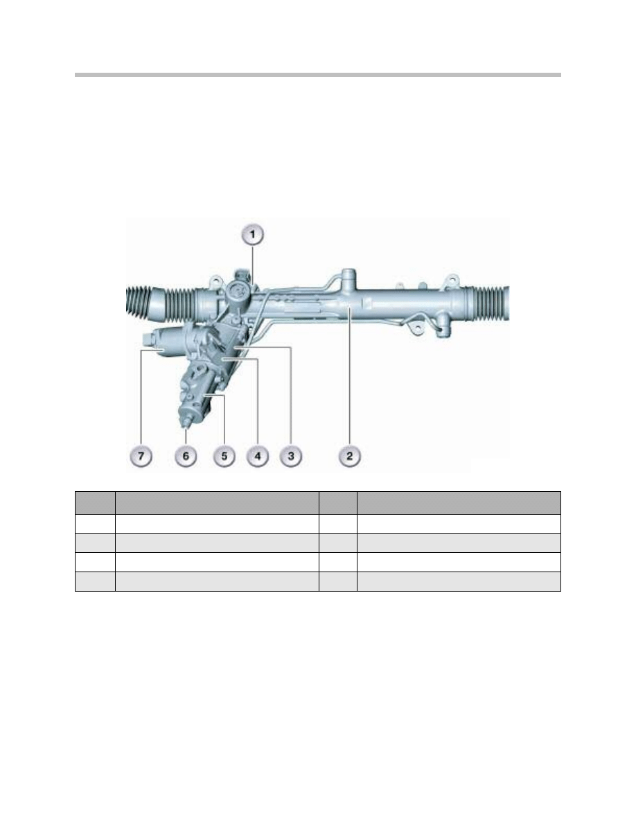
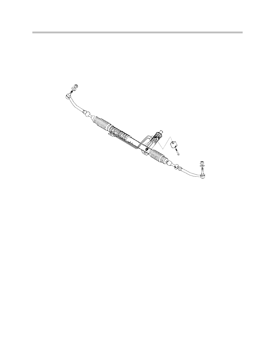
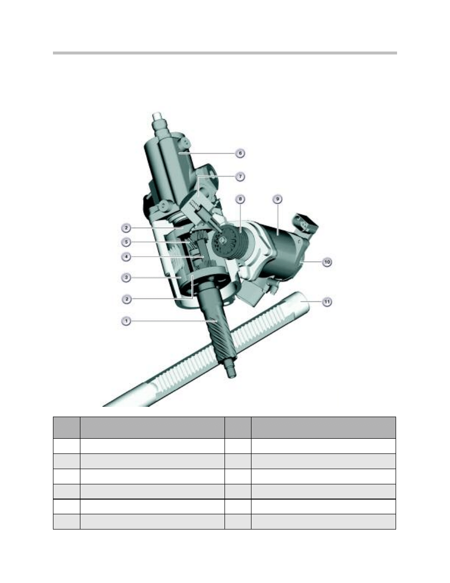
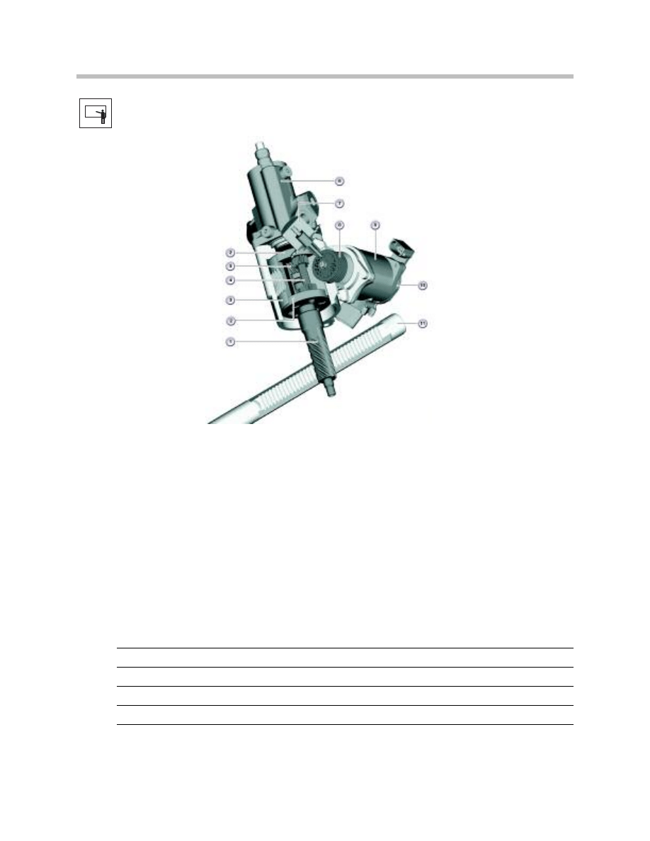
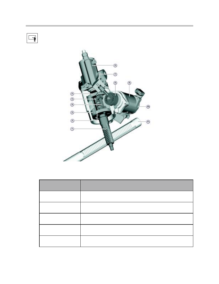
Steering Rack and Pinion Unit
The steering gear of the Active Steering system contains many of the components used
on a conventional steering gear with some additions. The planetary gear set and actuator
motor are located in series between the pinion gear and steering input shaft (6).
The core components of the active steering system is the actuating unit which contains a
planetary gear set which is actuated by a 3-phase DC motor.
24
Active Steering
Index
Explanation
Index
Explanation
1
Summation (total) steering angle sensor
5
Servotronic (spool valve) housing
2
Rack and Pinion steering gear
6
Steering spindle
3
Planetary gear housing
7
Actuator motor
4
Magnetic lock
25
Active Steering
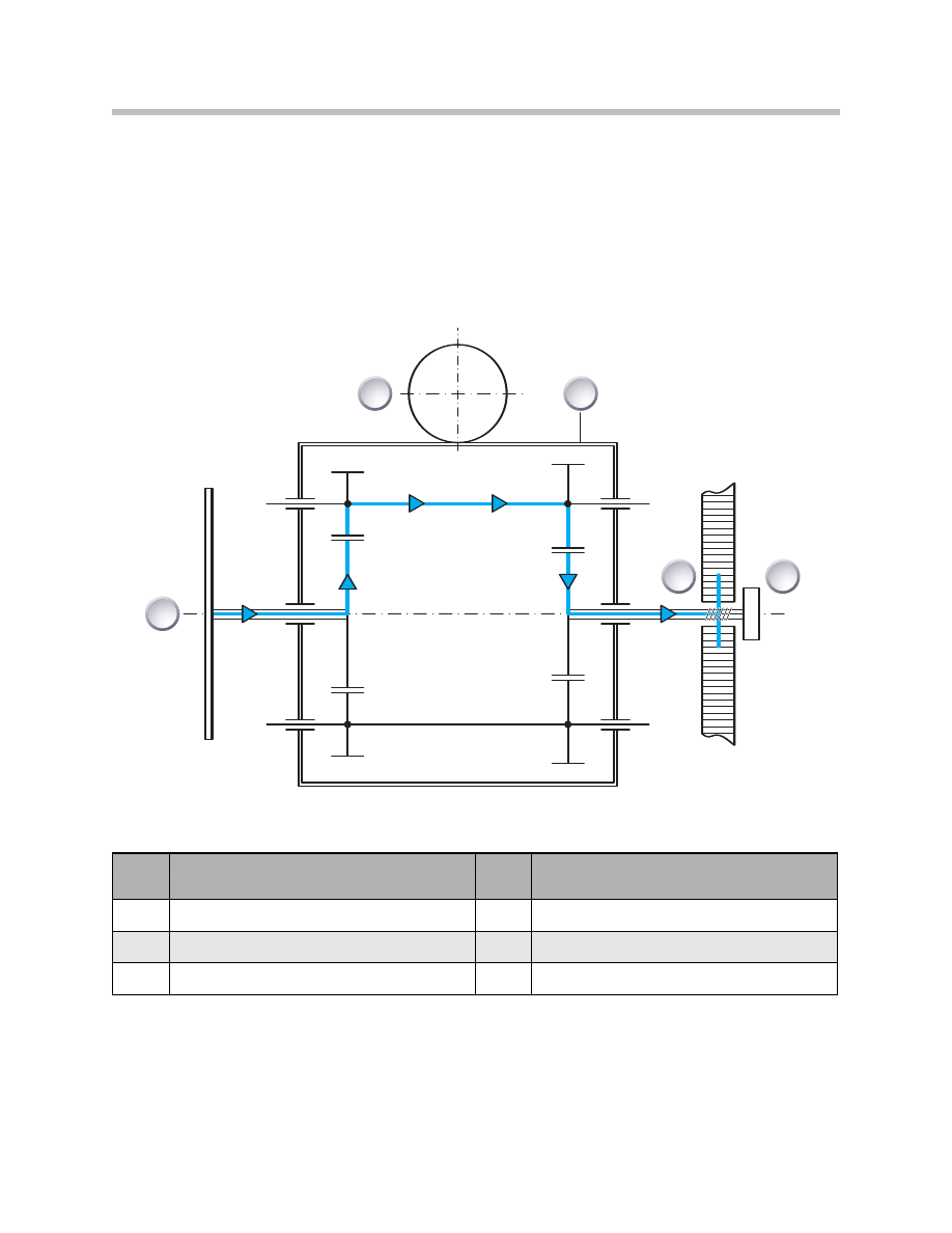
Planetary Gear Set
The input from the steering column is no longer directly connected to the pinion gear of
the rack and pinion unit. In the case of active steering, the steering input is now directed
to a member of the planetary gear set, specifically one of the “sun gears”.
The pinion gear is now driven by an additional sun gear in the planetary gear set. The
two “sun gears” are connected by a set of planet pinions which are used to drive the two
“sun” gears.
T
F
0
4
-
5
7
6
8
3
2
1
4
5
Index
Explanation
Index
Explanation
1
Steering wheel and input pinion (sun gear I)
4
Output pinion (sun gear II) meshed with rack
2
Actuator motor with worm drive connection
5
Cumulative (total) steering angle senor
3
Planetary carrier and external ring gear
26
Active Steering
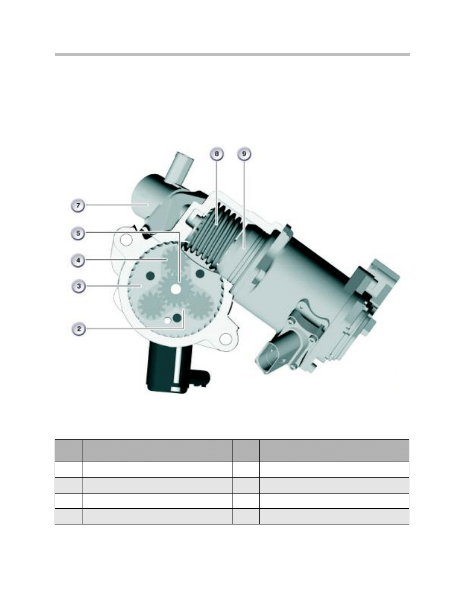
The ring gear of the planetary gear set is driven by a brushless, 3-phase DC motor which
is controlled by the AS control module. The actuator motor has a worm gear drive which
drives the “ring gear” of the planetary gear set externally.
Index
Explanation
Index
Explanation
1
Drive pinion
7
Electro-magnetic safety lock
2
Planetary gear (external ring gear)
8
Worm drive on actuator motor
3
Worm drive connection on ring gear
9
Electric actuator motor
4
Planetary gear (planet pinions)
10
Motor position sensor
5
Planetary gear (input sun gear)
11
Rack gear
6
Servotronic valve housing
27
Active Steering
The “worm drive” from the electric actuator motor is meshed with the outer surface of
the ring gear (a.k.a superimposing) gear. These planet pinions are also meshed both with
the “input sun gear” (from the steering input shaft) and the “output sun gear”(pinion).
They are NOT however, meshed with the planet pinions.
Index
Explanation
Index
Explanation
2
Planetary gear (ring gear)
7
Electro-magnetic safety lock
3
Worm drive connection on ring gear
8
Worm drive on actuator motor
4
Planetary gear (planet pinions)
9
Electric actuator motor
5
Planetary gear (input sun gear)
28
Active Steering
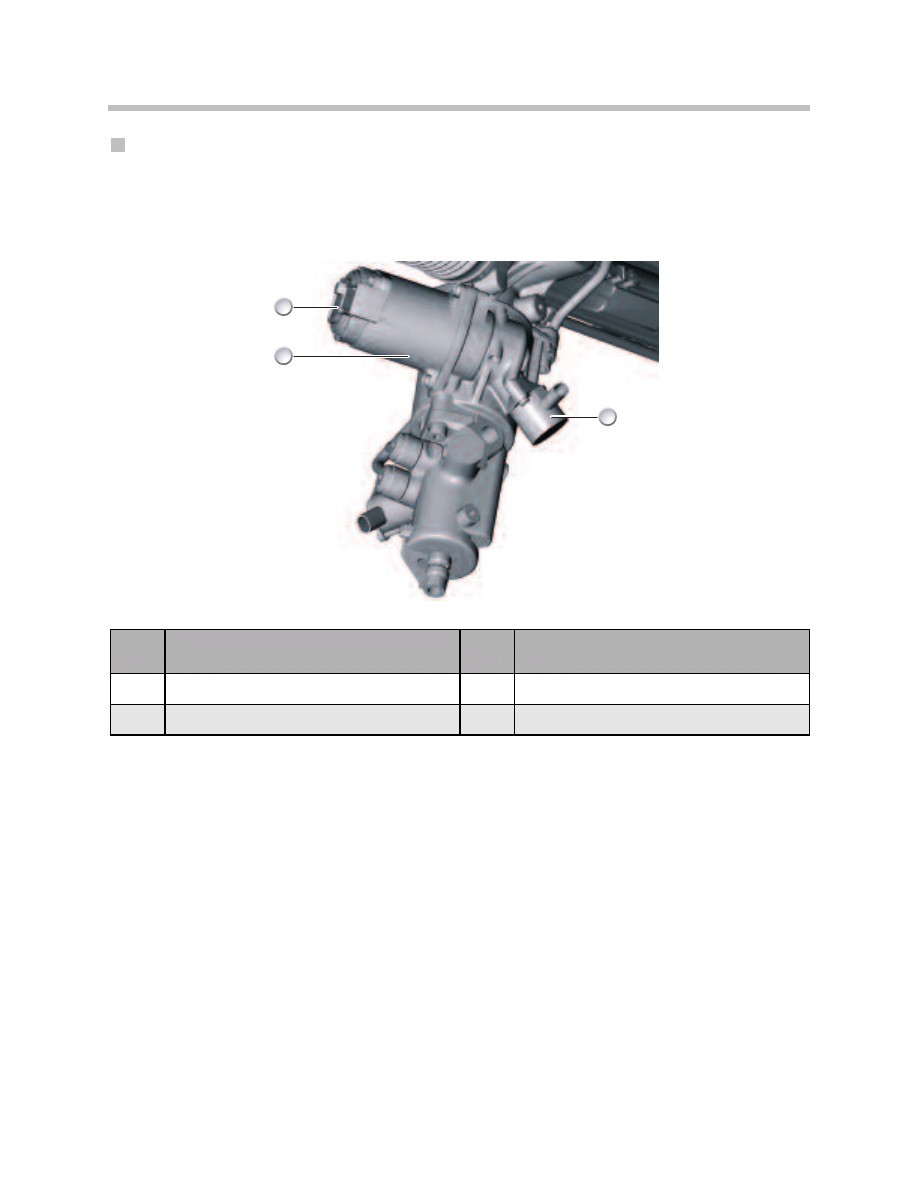
Safety Lock
An electro-magnetic (solenoid operated) safety lock is fitted to the actuator motor
housing. The lock is designed to hold the actuator motor in place during a system
malfunction for fail-safe operation. The ring gear, which is meshed to the worm drive,
is also held in place when the actuator motor is locked.
The safety lock is a spring loaded solenoid which is controlled by the AS control module.
The lock holds the actuator motor in place when no current is present. During normal
operation, the solenoid is unlocked by an applied current. When the current drops below
1.8 amps (approx. 3.16 V), the solenoid will spring to the locked position.
When a system fault occurs, safety lock prevents the ring gear from rotating freely. This
provides safe steering operation is the event of a system malfunction.
Be aware that there are other safety backups for the active steering such as the 3 -phase
actuator motor etc. The safety lock is an additional (redundant) safety device.
Note: Please be aware, at no time is the steering wheel mechanically discon-
nected from the steering rack. There is always a mechanical connection
present. During a system malfunction, the steering ratio may change
and possibly the steering angle may be off-center. However, the driver
always remains fully in control of the steering.
Index
Explanation
Index
Explanation
1
Actuator Motor
3
Safety Lock
2
Motor Position Sensor
T
F
0
4
-
5
4
1
2
2
3
1
29
Active Steering
Actuator Motor
The actuator motor is a 3-phase, synchronous, DC electric motor. It is controlled by the
active steering control module. The actuator motor drives the worm gear which is
meshed to the “ring gear” of the planetary gear set in the actuating unit housing. The
transmission ratio from the worm gear drive to the ring gear is 20.5:1.
The actuator motor provides the means for the active steering control module to vary the
steering ratio. The actuator motor does not provide the turning forces for the front
wheels. The turning forces are still provided by driver input and the power steering
system (i.e rack and pinion, power steering pump etc.)
The power supply of the electric motor has 3 phases for system safety. The electric
motor is only able to turn continuously if all 3 phases are supplied with current in
synchronization with the relevant position of the motor. The powered coil of the stator
drives the rotor of the electric motor, consisting of a permanent magnet. This procedure
is dependent on the magnetic field built up.
Index
Explanation
Index
Explanation
1
Electric actuator motor
3
Safety lock
2
Motor position sensor
30
Active Steering
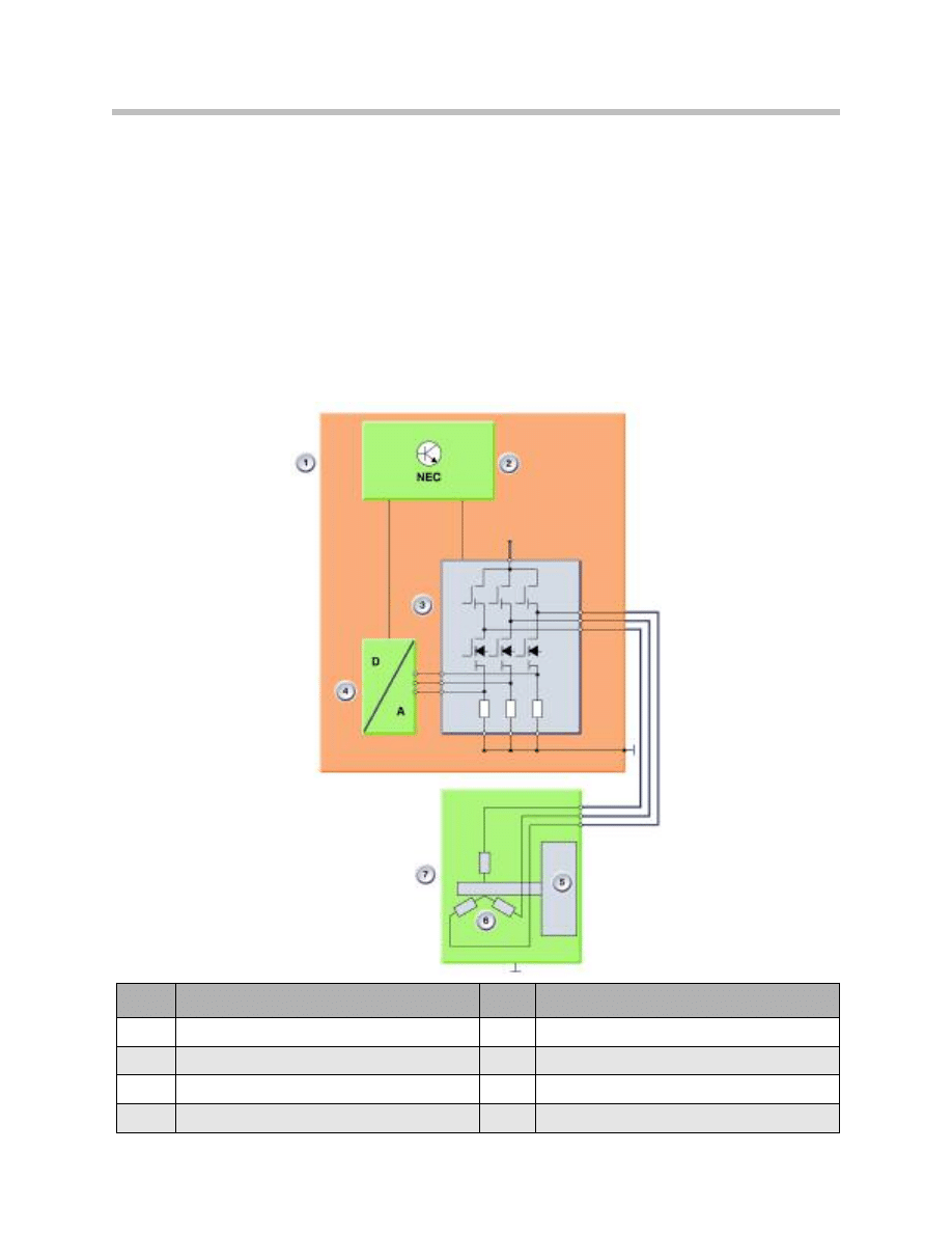
The rotor position is detected by the motor position sensor. The direction of rotation of
the electric motor is determined by the sequence in which the 3 phases are supplied
with current.
The electric motor is unable to turn continuously in the presence of a constant voltage,
e.g. due to defective components or short circuits (unlike an asynchronous motor).
Inadvertent turning (self-controlling) of the electric motor is prevented in the event of a
short circuit because the electric motor is unable to turn through more than 120°
( i.e. 3 x 120° = 360°).
By shorting the 3 phases, the motor is actively braked from fast operation and used to
shut down the system in the case of defects.
Index
Explanation
Index
Explanation
1
Active steering control module
5
Motor armature/rotor
2
Processor
6
Motor coils
3
Switching circuitry
7
Actuator motor
4
A/D converter
31
Active Steering
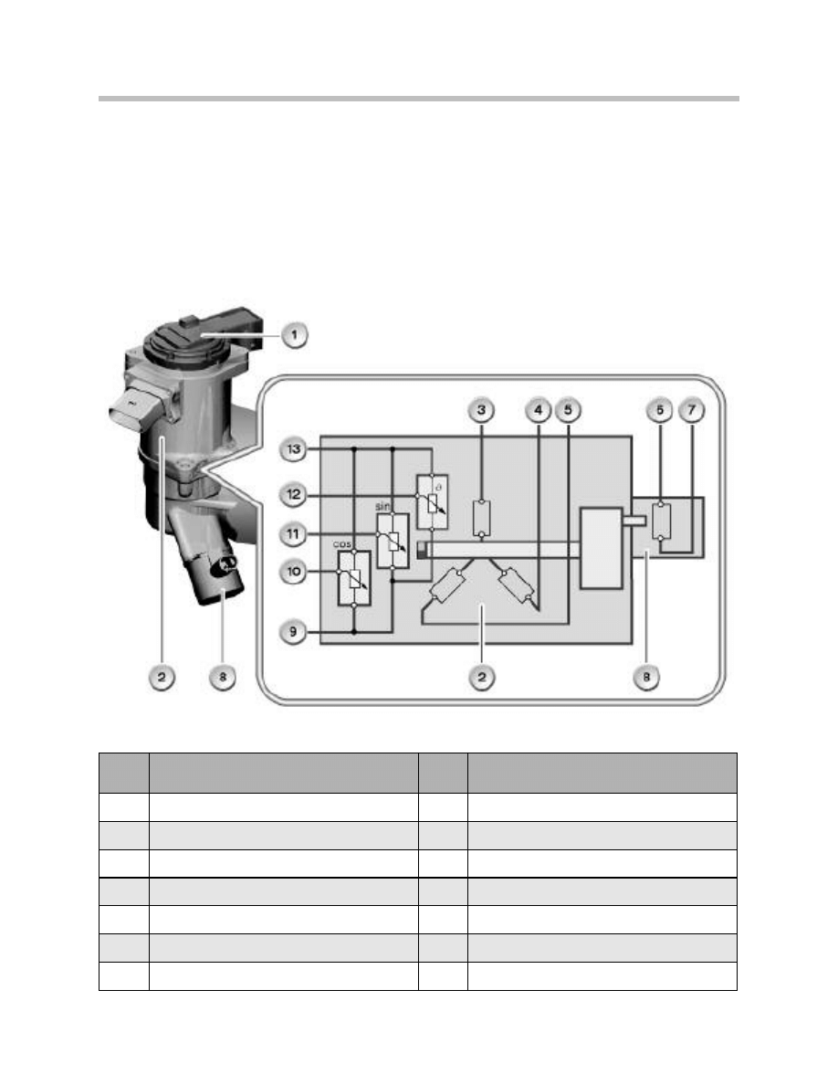
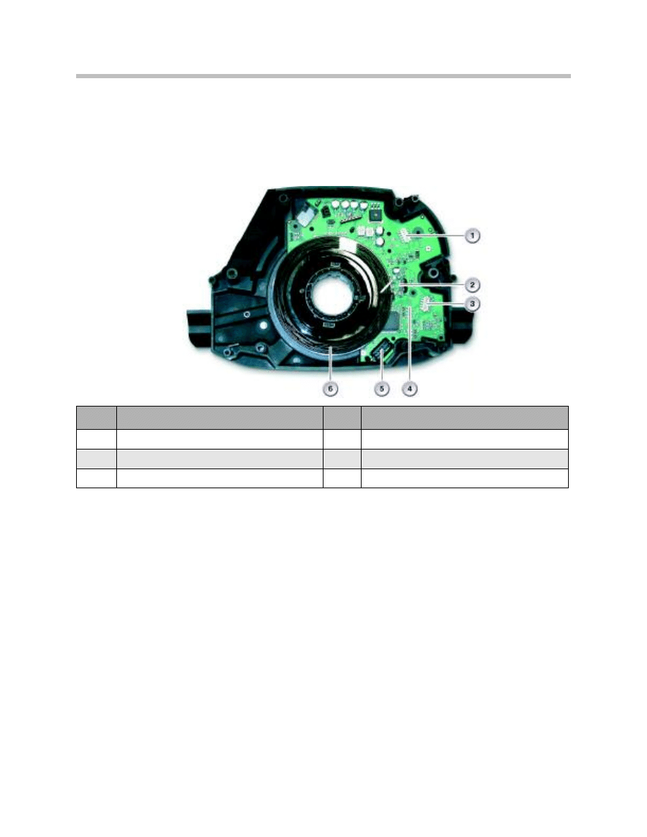
Actuator Motor Position Sensor
The motor position sensor is mounted on the actuator motor. The sensor is used to
detect the position of the rotor shaft and it operates on the magnetoresistive principle.
The motor-position sensor consists of a magnetoresistive element and a permanent
magnet. The permanent magnet is on the end face of the rotor shaft of the actuator
motor. The magnetoresistive element measures the magnetic field in the horizontal and
vertical directions.
Index
Explanation
Index
Explanation
1
Motor position sensor
8
Safety lock
2
Actuator motor (with worm gear drive)
9
Power supply (5V) for motor position sensor
3
Phase W of actuator motor
10
Signal 2 from motor position sensor
4
Phase V of actuator motor
11
Signal 1 from motor position sensor
5
Phase U of actuator motor
12
Signal from temperature sensor
6
Ground for safety lock
13
Ground
7
Power supply (B+) for safety lock
32
Active Steering
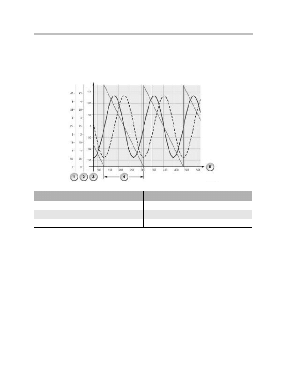
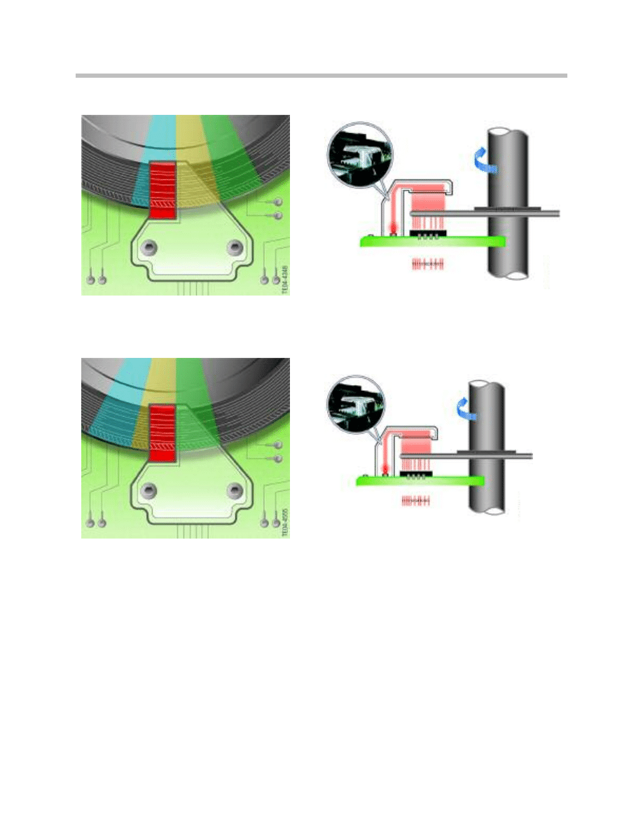
The motor-position sensor has a measuring range of 180°. The motor-position sensor
supplies 2 voltage signals. A rotation through 360° is based on 2 signal periods. The two
voltage signals are used to calculate the rotary position of the motor. The number of half
turns is counted by the AL control module, which stores this number in its memory when
the ignition is switched off.
Index
Explanation
Index
Explanation
1
Voltage signal 1
4
Signal period
2
Voltage signal 2
5
Angle of rotation
3
Calculated motor position
33
Active Steering
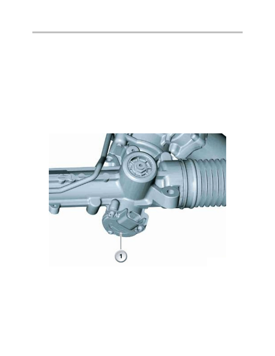
Total Steering Angle Sensor
On the active steering system, the steering angle sensor only detects the amount of the
driver’s “desired” steering input. The “actual” steering output is determined by the active
steering system according to road speed or vehicle dynamics.
Therefore, there is a second sensor which is used to detect the actual steering angle by
monitoring the position of the pinion shaft. This sensor monitors the “cumulative” or total
steering angle.
The total steering angle sensor is mounted at the base of the rack and pinion unit. The
sensor operates on the magnetoresistive principle and monitors a permanent magnet
affixed to the end of the pinion gear.
The total steering angle sensor (1) is calibrated at the factory and cannot be replaced as a
separate service part at this time.
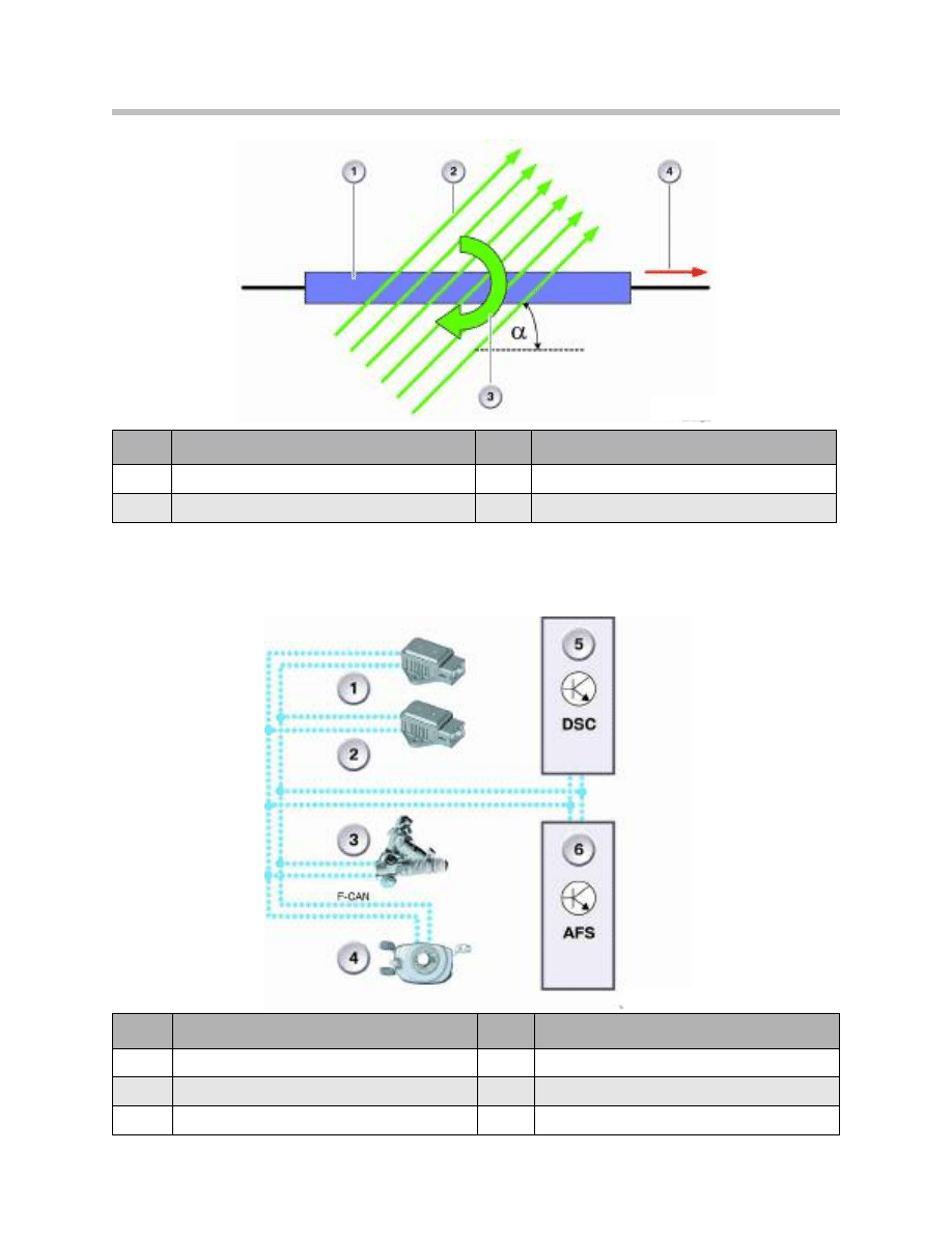
Magnetoresistive Element
The cumulative steering angle sensor operates in accordance with the magnetoresistive
principle. The magnetoresistive principle is based on the effect whereby the conductivity
of a ferromagnetic layer (magnetoresistive element) is altered by the influence of an exter-
nal magnetic field on the same plane as the layer. The change in resistance of the layer
depends on the direction (a) and strength of the external magnetic field.
34
Active Steering
Sensor Communication
The total steering angle sensor is communicates with the DSC and Active Steering
system via the Chassis CAN (F-CAN) system.
Index
Explanation
Index
Explanation
1
Magnetoresistive element
3
Direction of movement of the magnet
2
Magnetic field lines
4
Current flow
Index
Explanation
Index
Explanation
1
DSC sensor 1
4
Steering angle sensor (in SZL)
2
DSC sensor 2
5
Dynamic Stability Control
3
Total (cumulative) steering angle sensor
6
Active Steering
35
Active Steering
Steering Angle Sensor
The steering angle message is forwarded to the active steering control module by the
steering column switch cluster (SZL). There is a second processor in the SZL for the
redundant steering angle calculation. The second processor is only fitted if the vehicle is
equipped with active steering. The second processor is used for plausibility monitoring
of the signal.
The steering angle sensor is located in the steering column switch cluster. The steering
angle sensor is a potentiometer with two measuring elements offset by 90°. The
measuring elements offset by 90° ensure redundancy of the measurement voltage.
The redundant signals and possible electrical faults are monitored in the first processor.
This processor is also responsible for converting the voltage into the steering wheel
angle. For this conversion, a matching function must be included in the calculation,
which serves to calibrate the straight-ahead position of the steering wheel to the steering
wheel angle zero.
Since the sensor principle is only able to measure one revolution, the number of steering
wheel revolutions must be counted elsewhere. The output values on the byteflight and
the F-CAN are multi-turn values and contain the number of counted revolutions.
In addition to the signal processing for the DSC control module (F-CAN), the signals from
the second processor are digitized independently in the SZL for the active steering con-
trol module.
These single-turn values are sent to the active steering control module on a separate ser-
ial bus. This second path is dedicated to signal evaluation only. It is crucial that the
analog/digital conversion and serial processing take place independently of the first path.
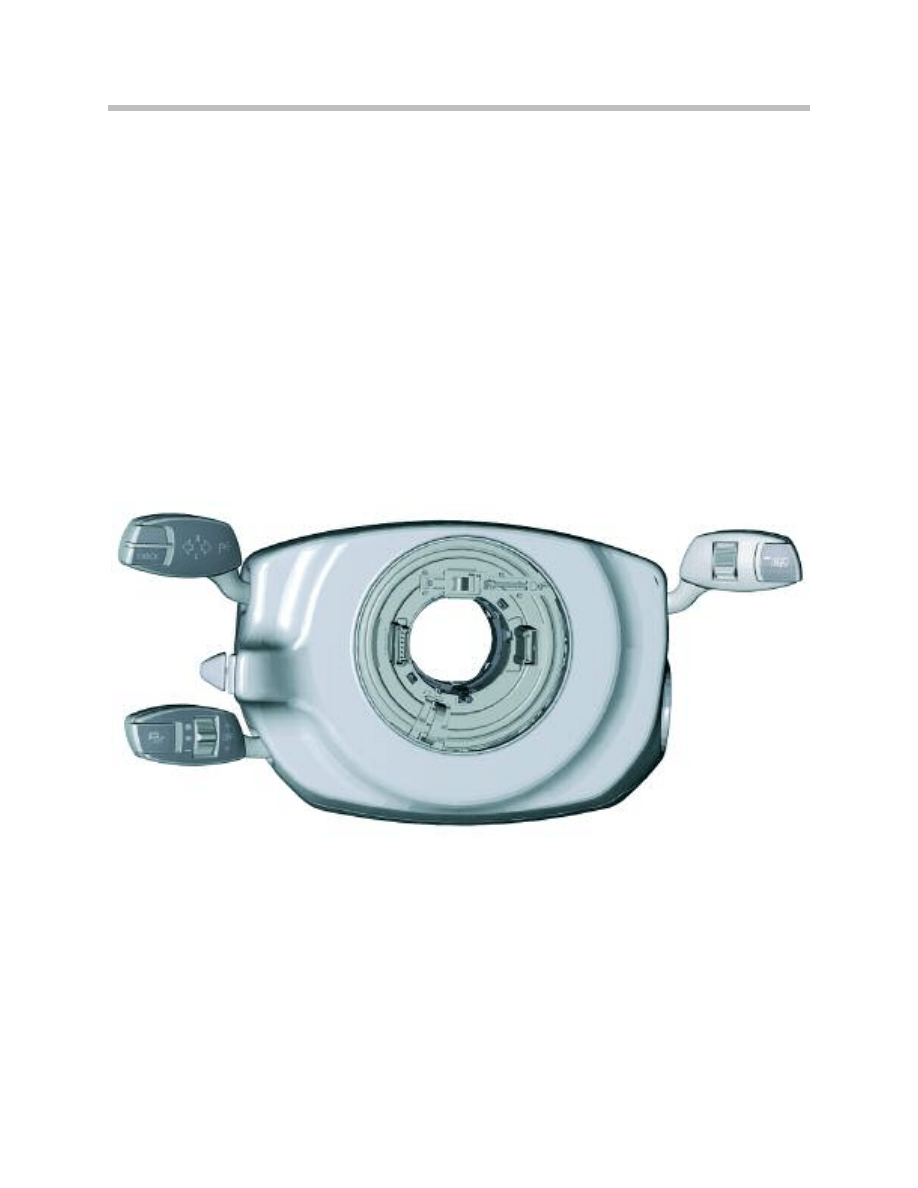
SZL Assembly on E60,E63 and E64 to 9/05
36
Active Steering
Steering Angle Sensor (from 9/05 and E90)
A new steering column switch cluster (SZL) will be installed in the models E60/E61/E63
and E64 as from 09/2005. This steering column switch cluster represents a combination
of technologies that are already familiar from various predecessor models.
Index
Explanation
Index
Explanation
1
DSC Module
4
Total Steering Angle Sensor
2
AFS Module
5
DSC Sensor
3
Steering Angle Sensor
Index
Explanation
Index
Explanation
1
Steering column switch, directional stalk switch
3
Coil Spring (clock spring)
2
Steering column switch, wipers
4
Steering column switch, cruise control
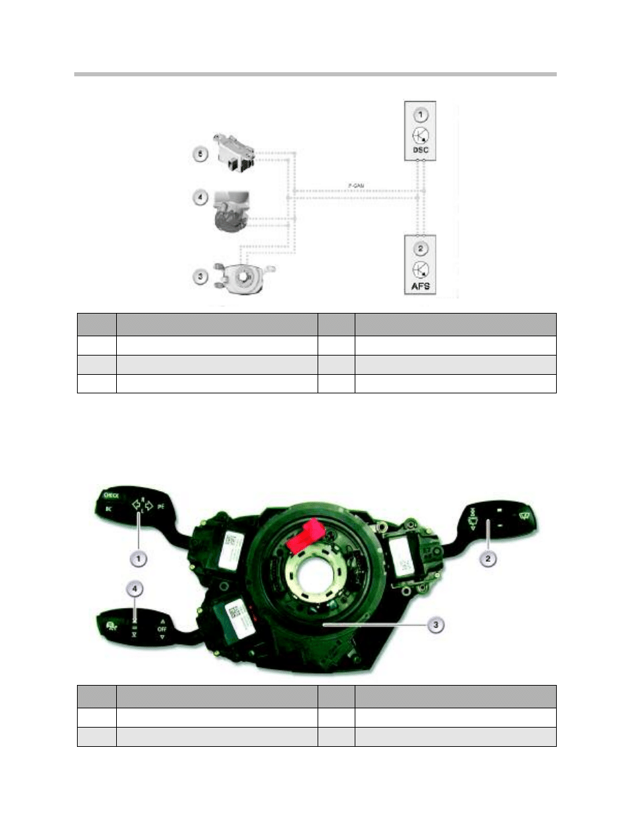
F-CAN Arrangement with SZL to 9/05
SZL E6X from 9/05
37
Active Steering
As on the E90, the steering angle is acquired by optical means. As on the E60/E65
models, the steering column stalks are equipped with electric buttons.
The two control modules previously responsible for this system (electronic steering wheel
module LRE and electronic steering column module LSE) have been combined in one
control module (steering column switch cluster).
Detecting Steering Angle
The steering angle sensor is designed as a contactless, optical angle measuring system.
The system consists of a code disc and an optical sensor. The code disc is connected
via a drive element directly to the steering wheel. The code disc turns within the optical
sensor when the steering wheel is moved.
The steering column switch cluster must detect the steering angle and steering speed
information as the basis for calculating various functions in the DSC.
Further information such as the absolute steering angle or the steering wheel rotation
information is calculated. A steering angle of - 180°/+180° is detected.
An LED and fiber optics unit illuminate the code disc from above. Due to the pattern on
the code disc, the light from above reaches the bottom only in certain areas where the
light beams hit the line camera. This process is similar to scanning bar codes on pack-
ages/goods purchased.
The line camera converts the line signals into electrical signals and transfers them to the
SZL.
Index
Explanation
Index
Explanation
1
Plug connection for cruise control stalk switch
4
Control module for SZL
2
Optical sensor for steering angle
5
Plug connection for wiper stalk switch
3
Plug connection for directional stalk switch
6
Code disc
E6X SZL internal view from 9/05
38
Active Steering
Section of Code Disc
Optical Sensor
The code disc rotates dependent on the
steering wheel angle setting. The pattern on
the code disc changes in steps of 2°.
The light beams hit the line camera. The light pulses
are converted to electrical pulses in the line sensor.
The pattern on the code disc changes as the
disc continues to turn. The light passes through
the code disc into other areas.
The position of the light beams is displaced. The line
camera detects the light beams in other areas and
transfers the information to the SZL.
Relative Steering Angle
The relative steering angle indicates the angle position of the steering wheel. The infor-
mation relating to the relative steering angle is always retained even when power to the
control unit is disconnected. Renewed zero adjustment is necessary only after the steer-
ing column switch cluster SZL has been replaced.
39
Active Steering
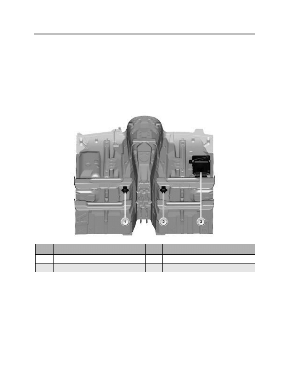
DSC Sensor
The lateral acceleration sensor and yaw-rate sensors are combined in a single housing
and designated the DSC sensor (sensor cluster). On the E6x vehicles up to 9/2005,
there are two DSC sensors installed on the vehicle. DSC sensor 1 is used for DSC
functions as well as Active Steering functions. DSC sensor 2 is used for the purpose of
signal redundancy and plausibility checking.
As for location DSC sensor 1 is located under the passenger seat to the right of the
transmission tunnel. DSC sensor 2 is under the driver’s seat to the left of the
transmission tunnel. On the 5 and 6 series (E6x) until 9/2005, DSC sensor 2 is only
installed on vehicles equipped with Active Steering.
From 9/2005, DSC sensor 2 has been eliminated from the vehicle. Therefore vehicles
with Active Steering only have 1 DSC sensor. Both sensors are connected to the
F-CAN.
On the E90, there is only one DSC sensor from the start of production. The sensor is
located under the driver’s seat.
Index
Explanation
Index
Explanation
1
DSC Sensor 2
3
Active steering control module
2
DSC Sensor 1
DSC Sensor Location (up to 9/05)
40
Active Steering
As far as design is concerned, the two DSC sensors are virtually identical. However, DSC
sensor 2 has an extra terminating resistor. The two DSC sensors have different part
numbers. In addition, each of the two DSC sensors has its own identification on the
CAN bus (CAN message). This excludes the possibility of confusing the DSC sensors.
The DSC sensors are a combination of lateral acceleration and rate-of-yaw sensors. The
DSC sensor consists of:
• Housing with connector
• Damper to prevent mechanical over-stressing
• Sensor element:
The sensor element consists of 2 piezoelectric acceleration sensors. A spring-mounted
weight is hung in the measuring cell of the acceleration sensor.
Sensor Operation
Each of the two DSC sensors supplies a rate-of-yaw signal and an acceleration signal.
Any accelerated motion accelerates the spring-mounted suspended mass. The force
needed to achieve this is generated by mechanical tension in the piezoelectric material.
This results in a shift in the electric charge. Electrodes are used to detect this shift,
which is output as an electric signal for processing.
The second DSC sensor implements redundancy in terms of registration of the signals
for lateral acceleration and rate of yaw. The fact that 2 DSC sensors are used means that
plausibility can be monitored. The two DSC sensors are triggered by the DSC control
module (excited every 10 milliseconds). Each time they are triggered, the two DSC sen-
sors send their signals to the F-CAN.
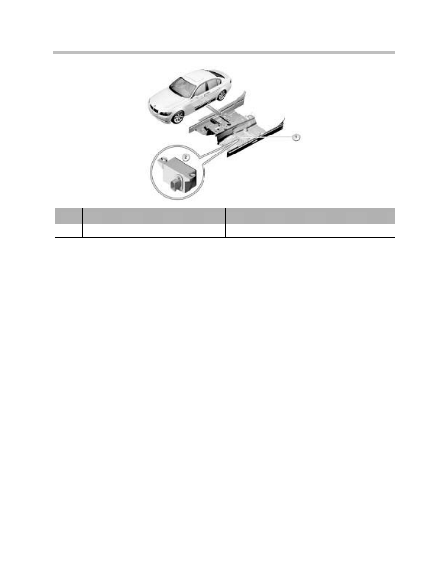
The 2nd DSC sensor is discontinued from 09/2005. 1 DSC sensor supplies redundant
signals.
Index
Explanation
Index
Explanation
1
Driver’s side seat crossmember
2
DSC sensor
DSC Sensor Location (E90)
41
Active Steering
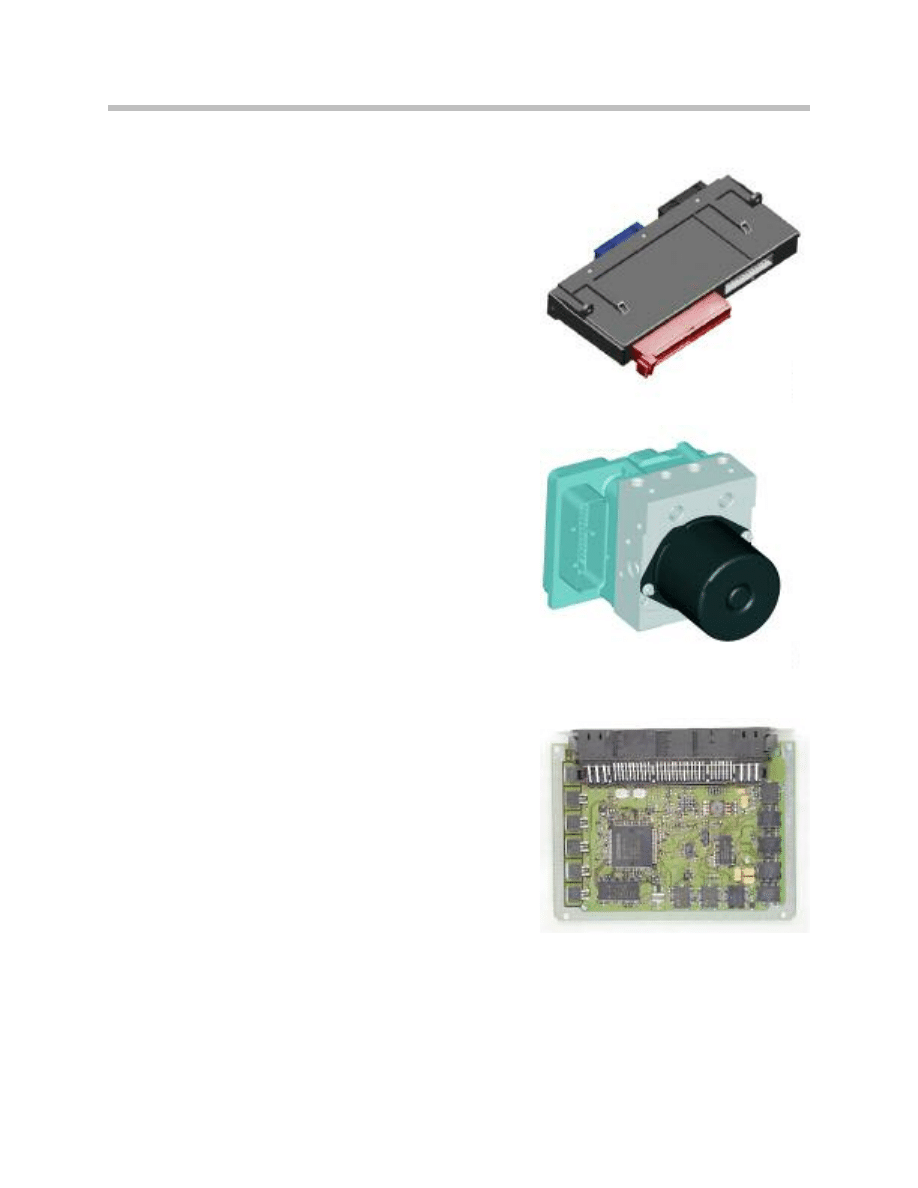
Active Steering Control Module
The control module for Active Steering (E6X) is located in the passenger-side footwell. It
is bolted to the floorpan (see illustration for DSC sensors). There is a protective bracket
(housing) to prevent damage from being stepped on.
On the E90/E91, the AS control module is located in the left hand wheel well area.
Module Construction
The AS control module housing has a stud for connecting the shield for the 3 phases
(U, V, W) of the electric servomotor. There are also two internal processors in the mod-
ule. The F-CAN connects the AS control module with the DSC module.
Module Function
The AS control module is integrated into the on-board network by the powertrain CAN
and the chassis CAN (F-CAN).
The function algorithms for calculating the nominal values for the operation of the electric
servomotor are stored in the AS control module.
In addition to the actual system functions, the control module has the following functions:
• Control of the power-steering pump
• Pre-drive-check
Index
Explanation
Index
Explanation
1
DSC Sensor 2
3
Active steering control module
2
DSC Sensor 1
42
Active Steering
The AS control module is initialized after the ignition is switched on (pre-drive-check).
The electric servomotor is not actuated while initialization is in progress. The sensor sig-
nals are checked and, if necessary, calibrated.
Safety Monitoring Functions
If errors are detected either the status changes directly to "Error" or rate-of-yaw control
is deactivated. When system status is "Error", activation of the electric servomotor is
disabled. The system status changes to "Drive" once initialization has completed
successfully.
• Sensor plausibility check
• Actuator monitoring
• Vehicle authentication (Checks with the Car Access System (CAS control module) to
ensure that drive authorization has been verified).
The AS control module uses the various input signals to compute the signals for actuat-
ing the electric servomotor.
Input signals are:
• Wheel speeds (wheel-speed sensors via DSC)
• Yaw rate and lateral acceleration (from the DSC sensor or sensors)
• Steering wheel angle (from the steering angle sensor)
• Total steering angle (from the total steering angle sensor)
• Position of the electric servomotor (from the motor-position sensor)
Changes from 9/2005
From 9/2005, the E6x vehicles utilize the AS control module design from the E90. The
hardware in the control module has also been changed to allow the control of the ECO
valve and the Servotronic solenoid as in the E90. The control module location remains
the same.
Active Steering control module location (E90)
43
Active Steering
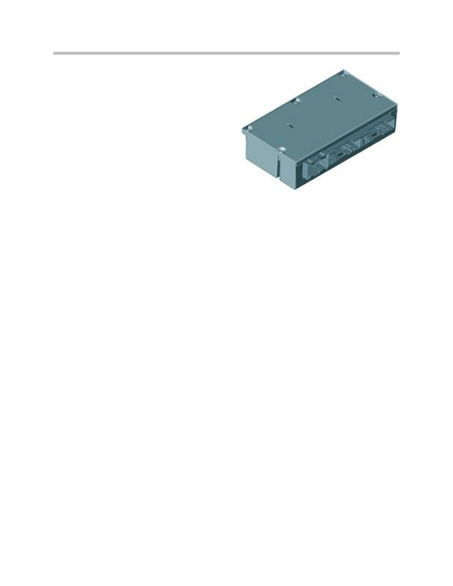
Safety and Gateway Module (SGM)
The SGM provides a “gateway” function
which is similar to the ZGM as used on the
early production E65. The SGM is used on
E6X vehicles. In addition to ZGM functions,
the SGM is responsible for the SIM functions
as well.
In the SGM housing, there are 2 separate
motherboards linked by CAN connection.
The output stages for controlling the
Servotronic valves and the ECO are integrated
in the SGM.
The SGM is located in the equipment carrier behind the glove compartment. The SGM
receives the volumetric flow information for controlling the Servotronic valve and the ECO
from the active steering control module. The signal from the SGM for controlling the
Servotronic valve and the ECO is pulse-width modulated.
The software for controlling the Servotronic valve and the ECO is installed in the SGM on
vehicles with active steering. The active steering control module sends the information
required for controlling the Servotronic valve and the ECO to the SGM. The information is
sent via the PT-CAN.
The software for controlling the Servotronic valve is installed in the SGM on vehicles with
active steering. No ECO valve is installed in vehicles without active steering.
Body and Gateway Module (KGM)
The body-gateway module KGM will be installed in the E60, E61, E63 and E64 as from
09/2005. The KGM replaces the former safety and gateway module (SGM). As far as the
active steering system is concerned, the KGM provides gateway functions for the bus
systems involved.
On vehicles that are
NOT equipped with active steering, the KGM controls the valve for
the Servotronic system. On vehicles equipped with active steering, the ECO valve is
controlled by the active steering control module.
It is connected via two 51-pin connectors to the system network and is installed in the
control unit carrier behind the glove compartment.
For more information on the KGM, refer to the training module “E6x 9/05 Model
Updates”.
44
Active Steering
Junction Box (E9X)
The junction box electronics (JBE) forms the inter-
face between the PT-CAN and the
K-CAN (signals for instrument cluster).
Moreover, the Active Steering control module
receives its power supply from the distributor in the
junction box.
The JBE is located behind the glove box in the
control unit carrier.
DSC Control Module
The DSC control module and the Active Steering
control module are interconnected by the F-CAN
(chassis CAN).
The signals supplied by the DSC control module
include the road speed signal.
ECM (DME)
The engine control module sends the signal which
indicates that the engine is running to the Active
Steering control module via the PT-CAN bus.
The AL control module notifies the engine control of
the approximate drive torque of the power-steering
pump.
CAS: Car Access System
The vehicle is authenticated by the Active Steering
control module and the CAS control module via the
K-CAN and PT-CAN (vehicle identification numbers
are compared).
Moreover, the CAS control module transmits the
wake-up signal for the PT-CAN.
JBE
DSC
ECM (DME)
45
Active Steering
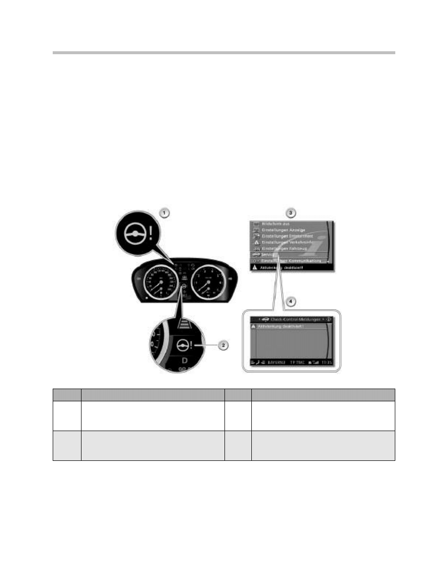
Warning Lights and Check Control
The dedicated-function warning light in the instrument cluster lights up to indicate a fault
in the Active Steering system.
At the same time a Check-Control message is shown in the LCD display. The text for the
Check-Control message can be called up in the Central Information Display (CID) if
equipped.
The following displays are present on the instrument cluster for the Active Steering:
• Dedicated-function warning and indicator light (required by law)
• LCD display showing the symbol for the Check Control
Index
Explanation
Index
Explanation
1
Dedicated-function warning and indicator
light for Active Steering required by law)
3
"Service" menu in Central Information
Display (CID)
2
Symbol for Check-Control message
4
Check-Control message in Central
Information Display (CID)

46
Active Steering
Operation
The driver receives indication of faults in the Active Steering system by means of the
following:
• via the dedicated-function warning and indicator light
• Check-Control message via symbol (yellow)
• text of the Check-Control message in the Central Information Display (with additional
informative text)
There are two Check-Control messages that can be issued in the event of a fault in the
Active Steering:
An error in Servotronic is only displayed by the Check Control.
The display is as follows:
Check-Control message in the status line in
the Central Information Display
Additional information text
Active Steering! Exercise care when steering.
Active Steering fault
Steering behavior altered. Steering wheel might be at
an angle. Possible to continue journey with caution.
Exercise care when steering! Have the problem
checked by the nearest BMW Service.
Active Steering inactive
Active Steering
Active Steering inactive.
Steering behavior altered. Steering wheel might be at
an angle. Possible to continue journey with caution.
Exercise care when steering!
Check-Control message in the status line in
the Central Information Display
Additional information text
Servotronic failure!
Servotronic failure
Possible to continue journey with caution.
Important: Power-steering assistance is no longer auto-
matically adapted to the vehicle's speed.
Have the problem checked by the nearest BMW
Service.

47
Active Steering
Functions of the active steering system include:
•
Steering assistance (function of Servotronic)
• Variable steering-gear ratio (function of Active Steering)
• Yaw-rate control (for damping of dynamic yaw)
The following new function has been added to the advanced development of the
E90/E91:
• Yaw moment compensation when braking on a road surface with unequal frictional
surfaces.
Steering Assistance
Power steering assist is carried out by conventional hydraulic steering (rack-and-pinion
construction).
Active Steering and Servotronic are mutual functions which together work to improve
steering effort during low speed maneuvers.
The Servotronic controls the degree of assistance provided by the hydraulic steering as
a function of the vehicle's speed. The flow of hydraulic fluid is restricted to a greater or
lesser extent depending on how the Servotronic valve is actuated. Restriction of the flow
depends on the current actuating the Servotronic valve.
The Servotronic is controlled by the following control modules depending upon model
and production date:
• E60, E61, E63, E64 up to 09/2005 - The safety and gateway module (SGM) actu-
ates the Servotronic valve.
In a vehicle fitted with Active Steering, the AS control module determines the nomi-
nal current for the Servotronic valve. In the event of the AL control module failing,
the SGM assumes the default value of the nominal current.
• E90, E91 and E60, E61, E63, E64 from 09/2005 - The Servotronic valve is actuat-
ed directly by the AL control module.
The signals and messages required for the Servotronic are as follows:
• Road speed from the DSC control module via the PT-CAN
• Status of the engine from the DME control module via the PT-CAN
• Terminal status of the CAS control module via the K-CAN
Active Steering Functions

48
Active Steering
The Servotronic valve is actuated only when terminal 15 is ON and the engine is running.
When the speed signal is present the default value of the nominal current is taken from
the characteristic map.
The current supply to the Servotronic valve is interrupted by the faults listed below. Under
these circumstances, steering assistance is limited to a minimum:
• Speed signal from the DSC control module incorrect or no speed signal
• Terminal status from CAS control module via K-CAN incorrect or missing
• Line fault to the Servotronic valve (exception: short-circuit to positive)
In the event of a short-circuit to positive, the entire on-board network voltage is applied to
the Servotronic valve. This means that the Servotronic valve is fully actuated. Under these
circumstances steering assistance is increased to maximum.
In vehicles without Active Steering, Servotronic is controlled directly by the safety and
gateway module (except E90/E91). Currently, on E90/E91, Servotronic is only available
on vehicles equipped with Active Steering.
Therefore, the steering assistance (Servotronic) and Active Steering systems work
together and complement one another. However, functionally, the two systems are fully
independent of each other.
49
Active Steering
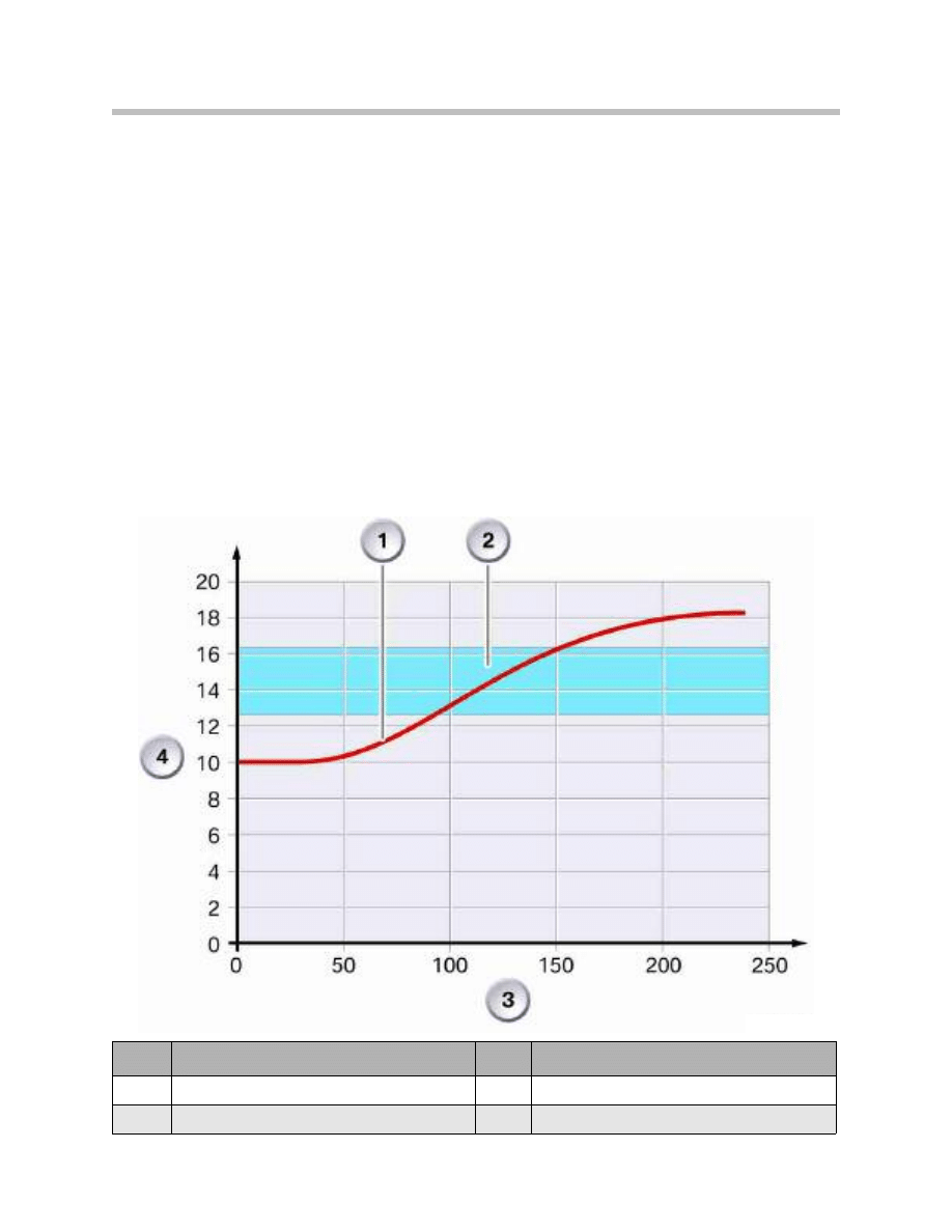
Variable Steering-gear Ratio
The actuator motor and planetary gear set in the rack and pinion unit make it possible to
vary the steering ratio to according to road speed. During low speed maneuvers, the
steering ratio is more direct (i.e. 10:1). The direct ratio allows the driver to apply the least
amount of driver input to achieve a larger amount of steering output.
For example, when the vehicle is stationary, less than two turns of the steering wheel are
required to turn the vehicle from lock to lock. Therefore parking and low speed turns
require less hand-to-hand “shuffling” of the steering wheel. This results in improved low
speed performance and increased safety. The driver is able to keep more continuous
contact with the steering wheel.
To achieve this, the actuator motor is driven in the same direction as the steering input.
This “decreases” the ratio which has the effect of “over-driving” the steering input.
This effect can be compared to walking on an escalator. Walking in the same direction as
the escalator will multiply overall input (walking).
Index
Explanation
Index
Explanation
1
Active steering design (variable ratio)
3
Road speed
2
Conventional design (fixed ratio)
4
Ratio

50
Active Steering
As road speed increases, the steering becomes less direct (high ratio e.g. 20:1). Sudden
steering movements by the driver are “dampened”. This increases safety by preventing
unwanted excessive “yaw” motion. The steering ratio is increased as road speed
increased.
In this case, the actuator motor is driven in the opposite direction as the steering input.
This increases the ratio which has the effect of “dampening” or “under-driving” of the
steering input.
This effect can be compared to walking
against the movement of an escalator. The
walking movement is somewhat cancelled by walking in the opposite direction of
escalator movement.
This increased ratio in combination with the increased “torque effect” of Servotronic, has
an improved effect on directional stability and road feel for the driver.
51
Active Steering
Yaw-rate Control
Before active steering systems became available, the Dynamic Stability Control (DSC)
system was largely responsible for correction of oversteer and understeer situations. The
DSC system detects excessive “yaw” and counters this action by applying the brakes at
the necessary wheels as needed.
With the introduction of Active Steering, the DSC is no longer the primary system for
intervention during these events. Now, the AS system can detect yaw moments as well.
For example, during a potential oversteer situation, the active steering system has the
capability to “counter-steer” before the driver perceives any excessive vehicle yaw. This
provides a stabilizing effect before the DSC system needs to intervene.
So, in this instance, the Active Steering system supports the DSC system. DSC will only
intervene when the stabilizing effect of Active Steering is insufficient to counteract the
tendency to yaw.
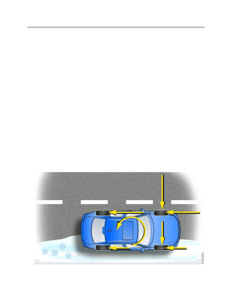
Yaw-moment Compensation (E90/E91)
On the E90/E91, Active Steering offers an additional function for driving stabilization.
With conventional systems, the driver has to actively steer the vehicle in a straight line if
the brakes are applied on a road surface with non-uniform traction levels.
In such situations, the Active Steering performs this active steering intervention, to
provide a stabilizing effect for the vehicle.
Compared to pure ABS control, Active Steering with yaw moment compensation
provides shortens the braking distance.
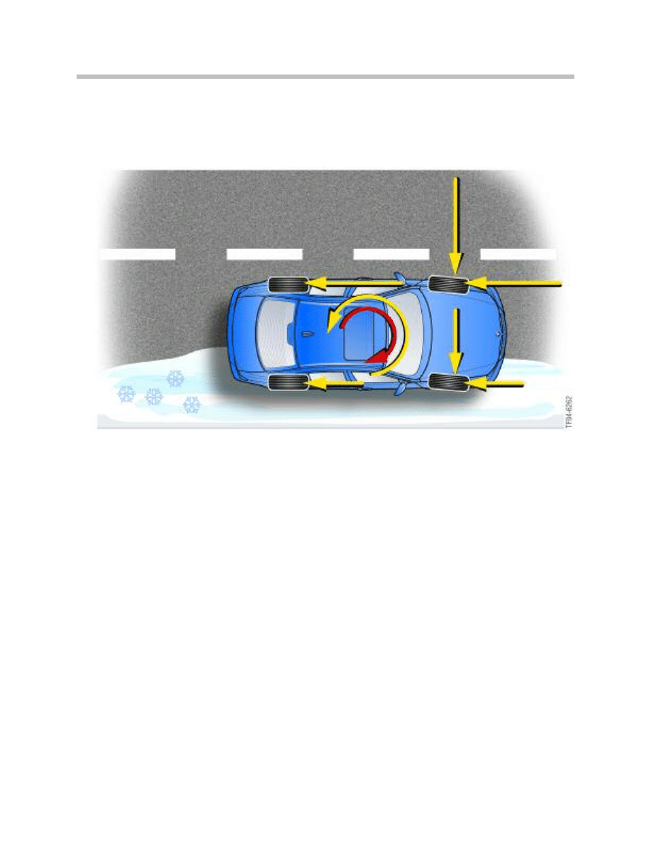
52
Active Steering
The function is accomplished by allowing the DSC control module to calculate the yaw
rate plus interpret information from the front steering angle sensor. The DSC control
module transmits the information to the AS control module which establishes the
yaw moment compensation correction angle needed for stabilization, counter steering.
The braking distance is shortened because higher braking pressure differences at the
rear axle are possible with yaw rate compensation via the steering. ABS on its own would
set significantly lower pressure than is actually possible at wheels on a high coefficient of
friction ("select low") and thus create a longer braking distance in this situation.
The driving stabilization function of the Active Steering can be deactivated together with
DSC with the DTC button (when DSC is completely deactivated). Together with the
hydraulic power steering, the variable steering-gear ratio is always active.

53
Active Steering
System Operation
Unlike DSC, which can be switched off by means of the DTC button, Active Steering
cannot be completely deactivated.
The functions of Yaw-rate control and yaw-moment compensation are deactivated when
DSC is switched off. However, the variable steering-gear ratio always remains active.
When DTC is active, the response thresholds for DSC are widened. Active Steering
increasingly assumes the function of driving stabilization if the vehicle is oversteered.
Preconditions for Activation
Preconditions for activation for Active Steering are:
• Terminal 15 ON
• The engine must be running
Steering-wheel position and the position of the steered wheels are synchronized as soon
as the engine is running.
This ensures that the positions of the steering wheel and the road wheels match if, for
example, the steering wheel was moved while the vehicle was at a standstill with the igni-
tion switched OFF.
Note: The synchronization procedure can cause the steering wheel or the
vehicle's front wheels to move.
Movements of the steering wheel or the vehicle's front wheels might be perceptible while
synchronization is in progress. Synchronization also occurs while the vehicle is on the
move, but the process is extremely slow and virtually imperceptible.
Fail Safe
A situation that would critically affect driving safety would be for the active steering to ini-
tiate steering movements on its own.
The safe system status (fail-safe) is when the actuator motor of the actuating unit is with-
out power. Irrespective of whether the safe status is initiated by loss of power or by
specific system shutdown, the fail-safe system ensures: the actuating unit does not
engage in the steering. The actuating unit is arrested by a lock that engages in the worm
drive of the actuating unit. The lock is pre-tensioned by a spring and held against this
pretension by the power supply. The actuator unit is inhibited by a break in the power
supply.
The arrested superimposed gear unit ensures that it is still possible for steering wheel
movements input by the driver to be transferred along the steering column. The steering
then responds in the same way as conventional steering. The purely mechanical
transmission between the steering wheel and the front wheels is retained.

54
Active Steering
The electric motor of the active steering actuating unit is connected to 3 phases. A short
circuit to earth will therefore prevent the electric motor from completing a full turn, the
maximum possible being only 120° (360° : 3).
The Servotronic valve switches under no electrical load to the fast driving characteristic
curve. The power steering assistance is reduced accordingly. The volumetric flow when
the ECO is without power is 7 liters/minute.
If the active steering control module does not send a valid message on the PT-CAN, the
SGM will operate with a speed-dependent substitute characteristic curve after 100 ms.
The substitute characteristic curve guarantees sufficient steering response for the
passive active steering system.
The driver is made aware of faults in the system in the form of an indicator lamp symbol
as well as check control messages in the instrument cluster.
The check control message reads:
Active steering failure! Steer with care.
The following or similar message will appear in the control display:
Steering behavior altered! Possible to continue the journey. Steering
wheel may be at an angle. Have the problem checked by the nearest
BMW Service.

55
Active Steering
NOTES
PAGE

56
Active Steering
Steering Angle Sensor Adjustment
A steering angle sensor adjustment (offset) must be carried out if the steering column
switch cluster (SZL) or the steering gear and rack are replaced.
The cumulative (total) steering angle sensor in the steering gear is calibrated to rack
center by the steering gear manufacturer.
Radio Reception Interference
Radio interference may be caused by a broken connection between the shielding of the
3 phases of the actuating unit to the housing of the active steering control modules.
Diagnostics and Coding
For diagnostics purposes, the active steering can be controlled as a control module in its
own right. The control module is an individual component.
Coding only enters vehicle-specific configurations.
Servotronic
Servotronic is activated in diagnosis as an independent control module, the output stage
for Servotronic is located in the SGM. Only the vehicle-specific configuration is entered
by way of coding.
AFS Initialization/Adjustment
The technician must perform the initialization/adjustment procedure after performing the
following work:
• Any alignment adjustments or steering component replacement
• Steering column work
• After replacement or programming of the AFS control module
• After replacement or programming of the SZL control module
A steering-angle adjustment (offset) must be carried out if the SZL or the steering rack
is replaced. This must be carried out on the KDS (alignment equipment).
The total steering-angle sensor on the steering gear is calibrated to the middle of the
rack at the steering-gear manufacturer.
The AFS adjustments can be found in the service functions menu of the DISplus/GT-1.
Workshop Hints

57
Active Steering
Wheel Alignment
If the vehicle requires a wheel alignment, the initialization procedure must be started
before beginning the alignment. Using the DISplus/GT-1, complete the following steps:
• Access the test module for “Startup adjustment/AFS. When prompted, answer
“Yes” to the alignment question.
• Center steering rack and check alignment marks on the steering gear
• Install tool # 324150 (tool not needed for E9X vehicles) and lock steering wheel
• Proceed with alignment
• After completing the last steps of the alignment (front toe adj), remove 324150.
• Proceed with the remaining portion of the test module.
This will set the total steering angle to 0 degrees by locking the superimposing gear (ring
gear). The AFS control module will de-energize the electromagnetic lock which will hold
the AFS actuator motor which will in turn hold the superimposing gear stationary. If align-
ment is attempted without performing this procedure, the steering will be off-center by a
considerable amount. Special tool # 324150 is used to hold the steering wheel in the
center position. Failure to use the special tool will result in an off-center steering wheel.
58
Active Steering
Classroom Exercise - Review Questions
1.
This question refers to the graphic show above. Which of the following compo-
nents below is responsible for preventing rotation of the actuator motor during
fail-safe conditions? (circle the correct answer)
1
2
3
4
5
6
7
8
9
10
11
2.
Using the above illustration (A), Which of the following components below is
responsible sensing the actuator motor position? (circle the correct answer)
1
2
3
4
5
6
7
8
9
10
11
3.
Briefly explain the definition of steering ratio:

59
Active Steering
Classroom Exercise - Review Questions
4.
Which of the following components is responsible for controlling the flow of the
power steering pump? (circle the correct answer)
Servotronic valve
ECO valve
Actuator motor
Electro-magnetic lock
5.
On E6X vehicles, produced after 9/2005, What control module is responsible for
controlling the Servotronic and ECO valves?
6.
Why is it necessary to have an ECO valve?
7.
What is the purpose of the second DSC sensor on an AFS equipped vehicle?
8.
Is it possible to de-activate the variable steering ratio of Active Steering using the
DTC button? (Explain answer.)
60
Active Steering
Classroom Exercise - Review Questions
9.
This question refers to the graphic show above. Fill in the correct number below
which corresponds to the functional description.
Number
Functional Description
Prevents rotation of the actuator motor during fail-safe situations
Carries planetary gears and meshes with worm drive
Output pinion meshed with rack
Provides active steering with actuator motor position information
Connects input pinion to output pinion

61
Active Steering
Classroom Exercise - Review Questions
10.
Which of the vehicles listed below are not available with Active Steering?
Cross out the vehicles which do not have (optional) Active Steering.
E60
E65
E66
E91
E83
E63
E39
E60 (M5)
E85
E53
E61
E92
E46
E90
E64
E38

62
Active Steering
Workshop Exercise - Active Steering Systems
On an AFS equipped vehicle perform the following tasks.
Using an AFS vehicle, start the engine and rotate the steering wheel from lock to
lock. Count the number of turns required to do this.
How many turns are required?
Using a similar vehicle
without AFS, perform the same task as above.
How many turns are required?
What is the difference between your results? (Explain answer.)
Using the proper diagnostic equipment, access the status requests for the following.
With the engine running, rotate the steering wheel (any direction) until the Driver’s
steering angle reads 90 degrees and record the cumulative steering angle below.
Are the two angles the same? (Explain answer.)
Turn the steering wheel back to the straight ahead position. Perform the same task
as above, but with engine off and ignition on. Record the results below.
Sensor
Position
Driver’s steering angle
90 degrees
Cumulative steering angle
Sensor
Position
Driver’s steering angle
90 degrees
Cumulative steering angle

63
Active Steering
Workshop Exercise - Active Steering Systems
Hold the steering wheel at 90 degrees (with the engine off). Start the vehicle, while
holding the steering wheel at 90 degrees and observe the front wheels.
What happens to the front wheels?
Return the steering wheel to the straight ahead position and switch off the engine.
Turn the steering wheel to 90 degrees (with the engine off). Release the steering
wheel, then start the engine and observe the steering wheel.
What happens to the steering wheel?
Remove underbody panels from the vehicle and access the plug connection for the
actuator motor. Start the vehicle and turn the steering wheel to the full lock position
and then disconnect the actuator motor. Return the steering wheel to the straight
ahead position.
What is observed regarding the steering wheel position as compared to the front wheels?
Observe status requests and compare to previous reading.
What is the difference?
When the actuator was disconnected, did you observe an audible “click” from the
vehicle when the system faulted?
If so, what caused this “click” sound?

64
Active Steering
Workshop Exercise - Active Steering Systems
What faults were set when the actuator motor was disconnected?
Re-connect the actuator motor and clear fault codes.
Proceed with the test plan for “Startup Adjustment/AFS”.
List the proper pathway to access this test module:
List the sequence of components adjusted during this procedure:
What is the difference between answering Yes or No at the beginning of this procedure?
When should the Startup/Adjustment be performed?
After completing the test plan, Is the steering wheel straight?
If not, repeat test plan until correct.

Workshop Exercise - Active Steering Systems
Perform a complete alignment on this vehicle:
Is special tool # 324150 needed to perform this alignment? Why or Why not?
List the steps for performing an alignment on a vehicle equipped with AFS:
List any special tools required to complete this alignment:
65
Active Steering
Document Outline
- Main Menu
- Introduction to Chassis Dynamics
- Steering Systems
- Active Steering
- Electric Power Steering
- Traction and Stability Systems
- DSC
- DSC8+
- xDrive with DCS8
- xDrive with DCS8+
- Active Roll Stabilization
- Level Control Systems
- EHC and EHC II
- E61 Rear Air Suspension
- Electronic Damping Control
- Braking Systems
- Tire Pressure Monitoring Systems
Wyszukiwarka
Podobne podstrony:
06 E60 Active Front Steering
02a URAZY CZASZKOWO MÓZGOWE OGÓLNIE 2008 11 08
MT st w 02a
ActiveD
Active new pl 200605
02a MIKRO
Flavon Active dopping EN
Active Directory
02a KONTO KSIĘGOWE
Active Directory
17 steering system
50 Steering Column
50 Steering Column
Ćw 02a Odporność wrodzona i nabyta Fagocytoza
Active Listening en id 51008 Nieznany (2)
lab 02a
MetStatChem 02a notatki
C 06 0 SteeringGearFailure
active
więcej podobnych podstron