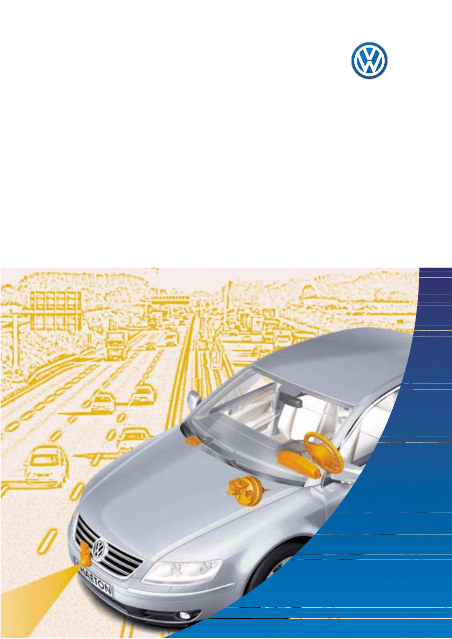
The Phaeton
Automatic Proximity Control (APC)
Design and Function
Self-Study Programme 276
Service.
2
NEW Important
Note
This Self-Study Programme explains the design
and function of new developments. The contents
will not be updated.
Please refer to the relevant Service Literature for current inspection,
adjustment and repair instructions.
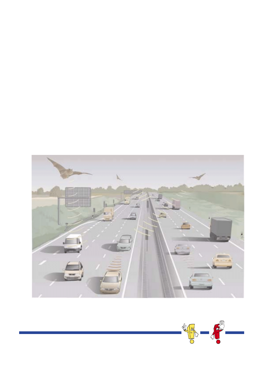
If a driver attempts to activate the vehicle's cruise control system (CCS) in the heavy traffic scenario
shown below to cruise along in a relaxed manner, he will soon have to brake because of the frequently
changing distances to vehicles ahead.
The APC system has learned its lesson from bats. In much the same way as bats use ultrasonic waves to
find their way about their surroundings, the Automatic Distance Control (APC) scans the traffic situation
ahead of the vehicle by means of millimetre wave radar and controls the distance to the vehicle ahead
on the basis of this data.
The CCS can be expanded to include a proximity-maintaining function which allows comfortable and
stress-free driving even in heavy traffic.
S276_034

3
Table of contents
Introduction . . . . . . . . . . . . . . . . . . . . . . . . . . . . . . . . . . . . . . 4
Overview . . . . . . . . . . . . . . . . . . . . . . . . . . . . . . . . . . . . . . . . . . . . . 4
Functional description . . . . . . . . . . . . . . . . . . . . . . . . . . . . . . . . . . . 6
Functional limits . . . . . . . . . . . . . . . . . . . . . . . . . . . . . . . . . . . . . . . . 8
System overview. . . . . . . . . . . . . . . . . . . . . . . . . . . . . . . . . . . . . . . 10
Components of the APC system . . . . . . . . . . . . . . . . . . . . . 12
Multi-function steering wheel . . . . . . . . . . . . . . . . . . . . . . . . . . . . 12
APC display in the dash panel insert. . . . . . . . . . . . . . . . . . . . . . .15
Accelerator, brake pedal and selector lever. . . . . . . . . . . . . . . . 19
Proximity control sender G 259 . . . . . . . . . . . . . . . . . . . . . . . . . . 20
Brake servo control unit. . . . . . . . . . . . . . . . . . . . . . . . . . . . . . . . . 22
Anti-theft alarm . . . . . . . . . . . . . . . . . . . . . . . . . . . . . . . . . . . . . . . 23
Electronic brake servo . . . . . . . . . . . . . . . . . . . . . . . . . . . . . . . . . . 24
Data flow in the CAN network . . . . . . . . . . . . . . . . . . . . . . . . . . . 28
Service . . . . . . . . . . . . . . . . . . . . . . . . . . . . . . . . . . . . . . . . . 30
Calibrating the proximity control sender. . . . . . . . . . . . . . . . . . . 30
Measuring method . . . . . . . . . . . . . . . . . . . . . . . . . . . . . . . . . . . . .31
Correcting an indication error . . . . . . . . . . . . . . . . . . . . . . . . . . . 33
System safety . . . . . . . . . . . . . . . . . . . . . . . . . . . . . . . . . . . . . . . . . 34
Diagnostics . . . . . . . . . . . . . . . . . . . . . . . . . . . . . . . . . . . . . . . . . . . 35
Glossary . . . . . . . . . . . . . . . . . . . . . . . . . . . . . . . . . . . . . . . . 36
Terms in italics are explained here . . . . . . . . . . . . . . . . . . . 36
Test your knowledge . . . . . . . . . . . . . . . . . . . . . . . . . . . . . . 38
4
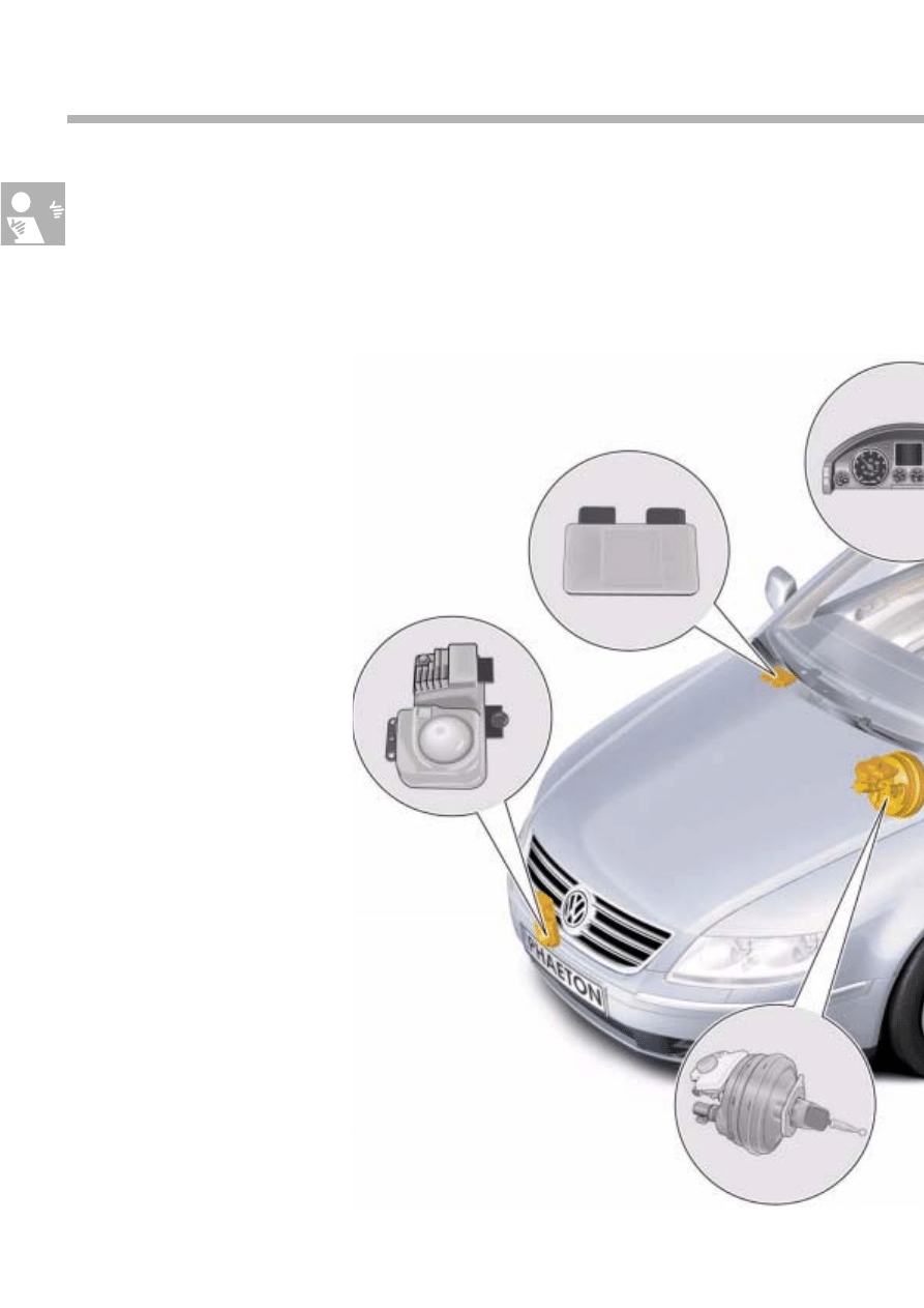
Overview
APC
The Automatic Proximity Control system is an
expansion of the conventional cruise control
system (CCS). The CCS adjusts the speed of the
vehicle to a value preset by the driver.
The APC system implements this convenience
function in the same way. In addition, the
vehicle's road speed is adapted to the speed of
any vehicle driving ahead if the latter is moving
more slowly than one's own vehicle.
Introduction
Dash panel insert with 5‘‘ colour screen
Proximity control sender
Brake servo control unit
Electronic brake servo
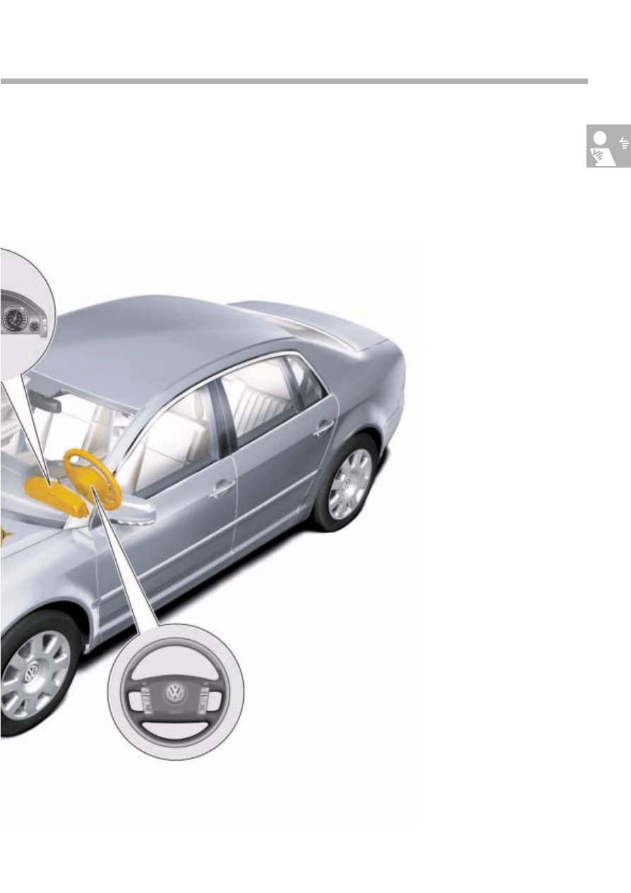
5
Automatic Proximity Control is a
driver assistance
system designed for enhanced convenience.
It relieves the strain on the driver while driving
and thus contributes to active safety.
S276_056
Multi-function steering wheel
6
Functional description
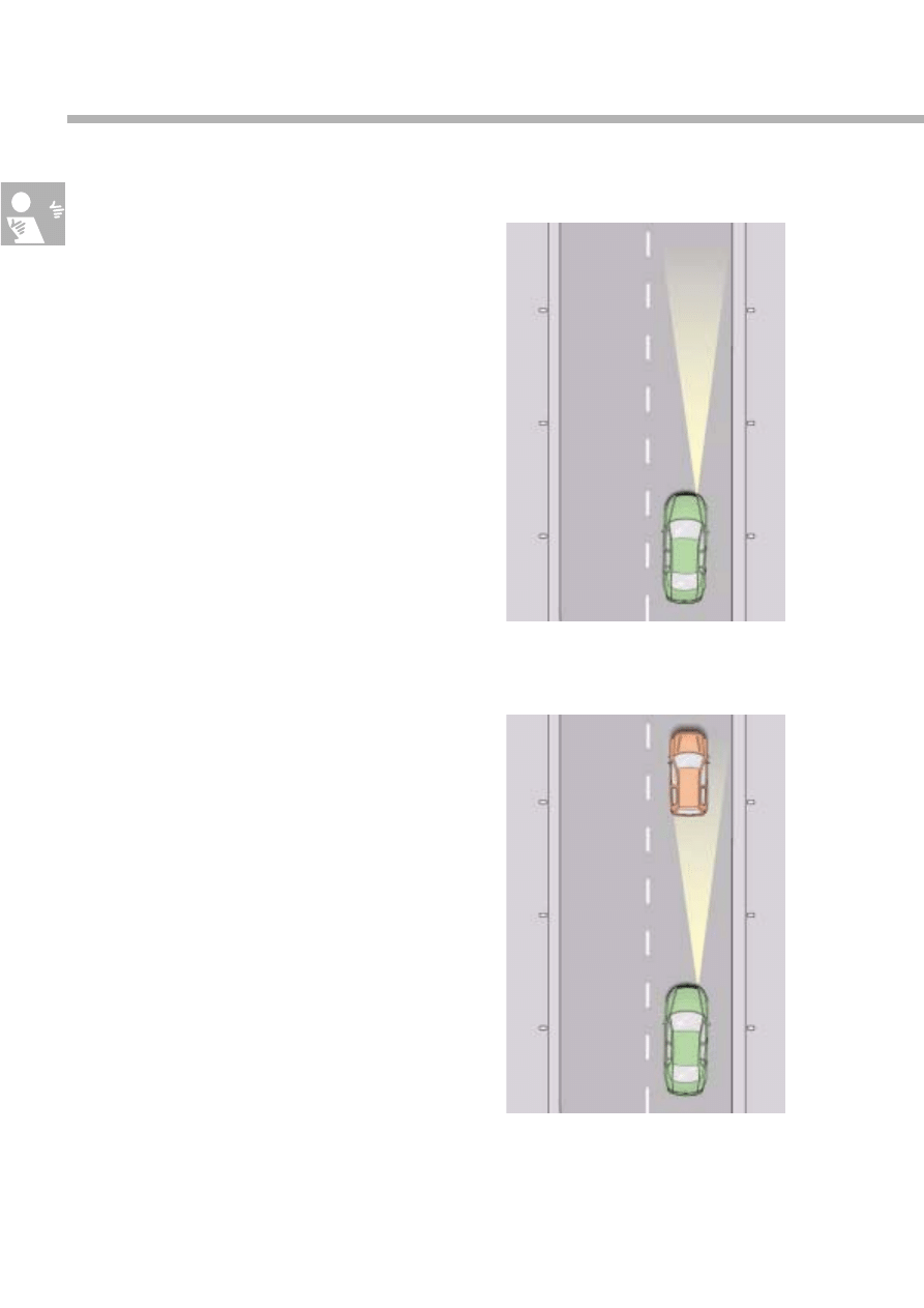
Constant speed
If no vehicle is located within the field of vision of
the proximity control sender, the
desired speed
is
maintained.
Deceleration
If an APC-controlled vehicle (green) detects a
slower vehicle (red) ahead of it in the same lane,
the APC regulates the intervehicular distance to a
time-dependent value pre-selected by the driver
by reducing the engine torque and, where neces-
sary, by moderately applying the brakes.
Introduction
S276_006
100 kph
S276_007
100 kph
80 kph
80 kph
7
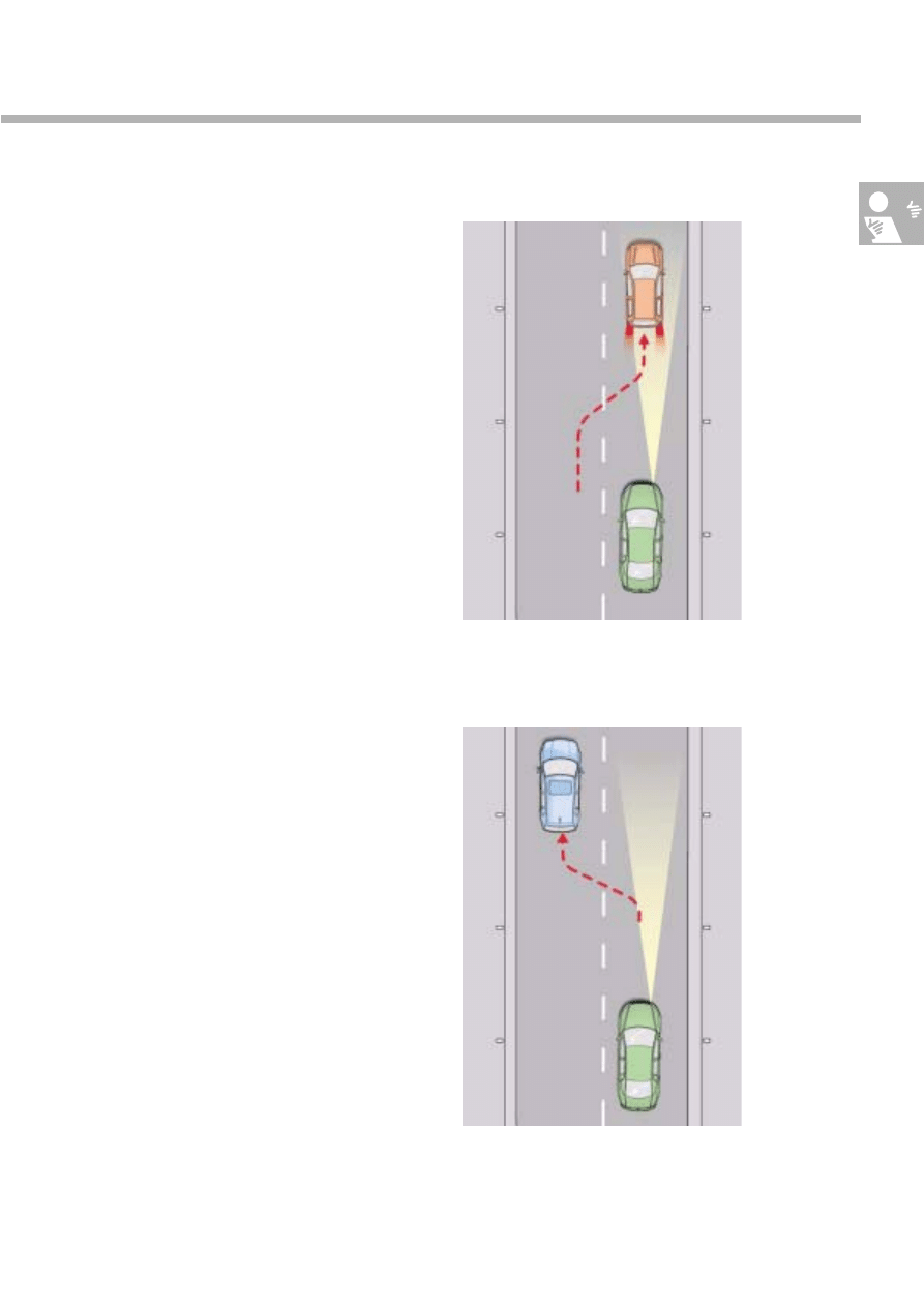
The APC also reacts to slower-moving vehicles
which cut in ahead by decelerating.
The vehicle road speed is adapted accordingly.
Acceleration
If the vehicle in front clears the way by accelera-
ting or by changing lane, the APC
re-accelerates to the pre-selected speed.
S276_009
80 kph
100 kph
80 kph
120 kph
S276_03?7
100 kph
80 kph
80 kph
8
Functional limits
The APC has an upper speed limit of 180 kph.
This limit is defined by the proximity control sen-
der's range of 150m. High speeds require a long
stopping distance. A braking operation must then
be initiated at a large distance to the vehicle in
front.
If the APC is in the process of decelerating from
higher speeds, the driver is prompted to take
over the braking when the minimum function
speed is undershot.
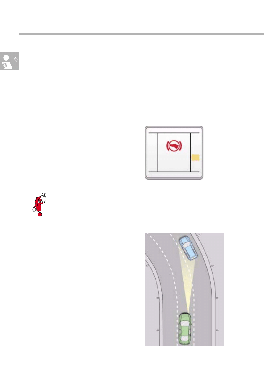
In the traffic scenario shown here, the lane
ahead of the green vehicle is also clear in the
curve, but the APC may possibly react to the blue
vehicle in the adjacent lane on the right. The
accuracy of the lane forecast comes up against
its limits at increasing distances to vehicles dri-
ving ahead, particularly in left-hand curves.
The proximity control sender suppresses all sta-
tionary objects within its field of vision. As a
result, there is also a minimum function speed of
30 kph below which the APC cannot be activa-
ted.
Introduction
Stationary vehicles are not detected as they are approached, and the
driver is required to perform a normal braking operation.
S276_063
S276_036
A
A
A
AP
P
P
PP
P
P
PL
L
L
LY
Y
Y
Y
B
B
B
BR
R
R
RA
A
A
AK
K
K
KE
E
E
E
P
P
P
P
R
R
R
R
N
N
N
N
D
D
D
D3
3
3
3
S
S
S
S
4
4
4
41
1
1
12
2
2
2.
.
.
.3
3
3
3
k
k
k
km
m
m
m
1
1
1
12
2
2
2.
.
.
.3
3
3
3
o
o
o
o
C
C
C
C
1
1
1
12
2
2
23
3
3
34
4
4
45
5
5
56
6
6
6
k
k
k
km
m
m
m
9
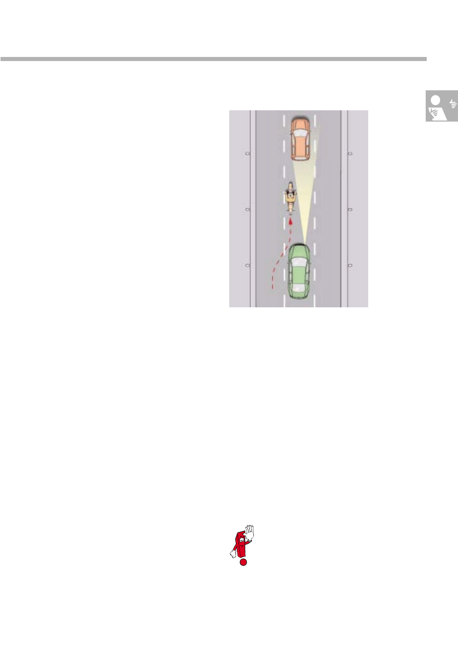
Another limitation arises from the sensor's nar-
row angle of vision of approx. 12°. In tight cor-
ners, the scanning range of the sensor may not
be wide enough. The APC is designed for curve
radii larger than 500 m.
Road users who cut in just ahead or are driving
at an offset angle, such as the motorcyclist in this
diagram, are outside the APC's field of vision, so
it is unable to react to these objects.
For comfort reasons, APC deceleration is limited
to approx. 30% max. deceleration. However, hig-
her rates of deceleration are necessary if the
vehicle approaches a vehicle driving ahead and
there is a large difference in speed between the
two vehicles. The APC then prompts the driver to
take over the braking operation.
It can generally be said that the APC can only
react as expected if
●
the proximity control sender has correctly
detected the distance, relative speed and
reflection angle
of objects ahead of the
vehicle and
●
the electronics have assessed the situation cor-
rectly.
This is the case when a vehicle is displayed in the
central display.
APC is designed for operation on
motorways and country roads that are
mainly straight.
S276_035
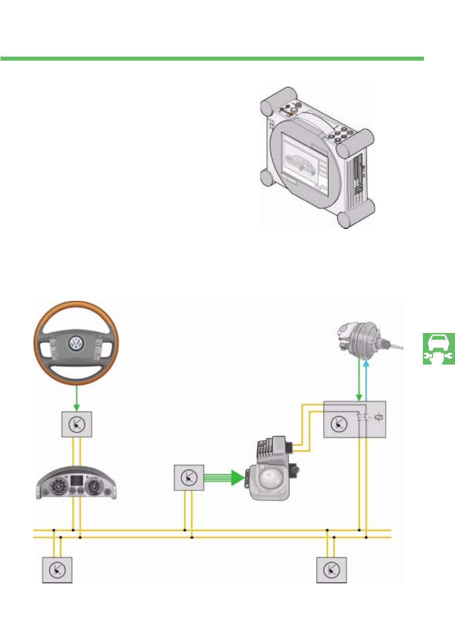
10
System overview
The APC system is integrated into the vehicle's
drive train electronics. Data is exchanged with
the engine electronics, ESP and the gearbox con-
trol via the drive train CAN databus.
The engine speed signals generated by the wheel
sensors are sent directly to the proximity control
sender from the ABS with EDL control unit to
ensure a sufficiently accurate
lane forecast
.
Introduction
Multi-function steering wheel
J 453
Steering column electronics
control unit
J 527
Convenience CAN
databus
Control unit with display in dash
panel insert
J 285
Engine control unit
J ...
ABS with EDL control unit
J 104
11
S276_057
Proximity control sender,
right
G 259
Drive train
CAN data-
bus
Electronic
brake servo
Brake servo control unit with bus relay
J 539
Drive train CAN databus
Automatic gearbox control unit
J 217
Wheel speeds
12
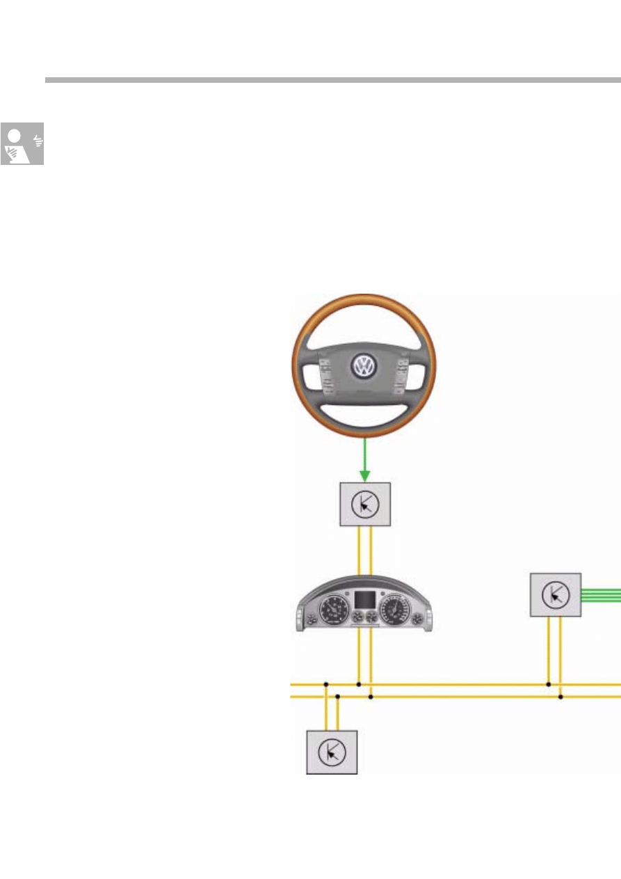
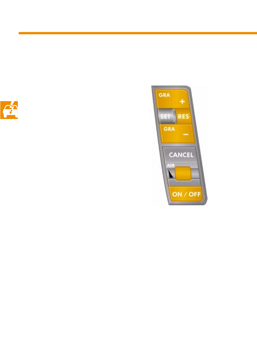
Multi-function steering wheel
The APC system is mainly operated via the but-
tons in the multi-function steering wheel, but it
can also be operated like the cruise control
system via the accelerator and brake pedal. The
steering wheel buttons are connected to the
stee-
ring column electronics control unit
which sends
the data to the dash panel insert via the conveni-
ence CAN databus.
The
gateway
in the dash panel insert assumes
the data exchange function between the conve-
nience CAN databus and the drive train CAN
databus.
To ensure that the driver is informed about the
APC's functional state at all times, the following
information is displayed in the dash panel insert
and partly supported by acoustic signals:
●
APC status
●
Driver inputs
●
Warnings
Components of the APC system
S276_041
Steering column
electronics control
unit
J527
Dash panel insert
Convenience
CAN databus
Drive train CAN
databus
13
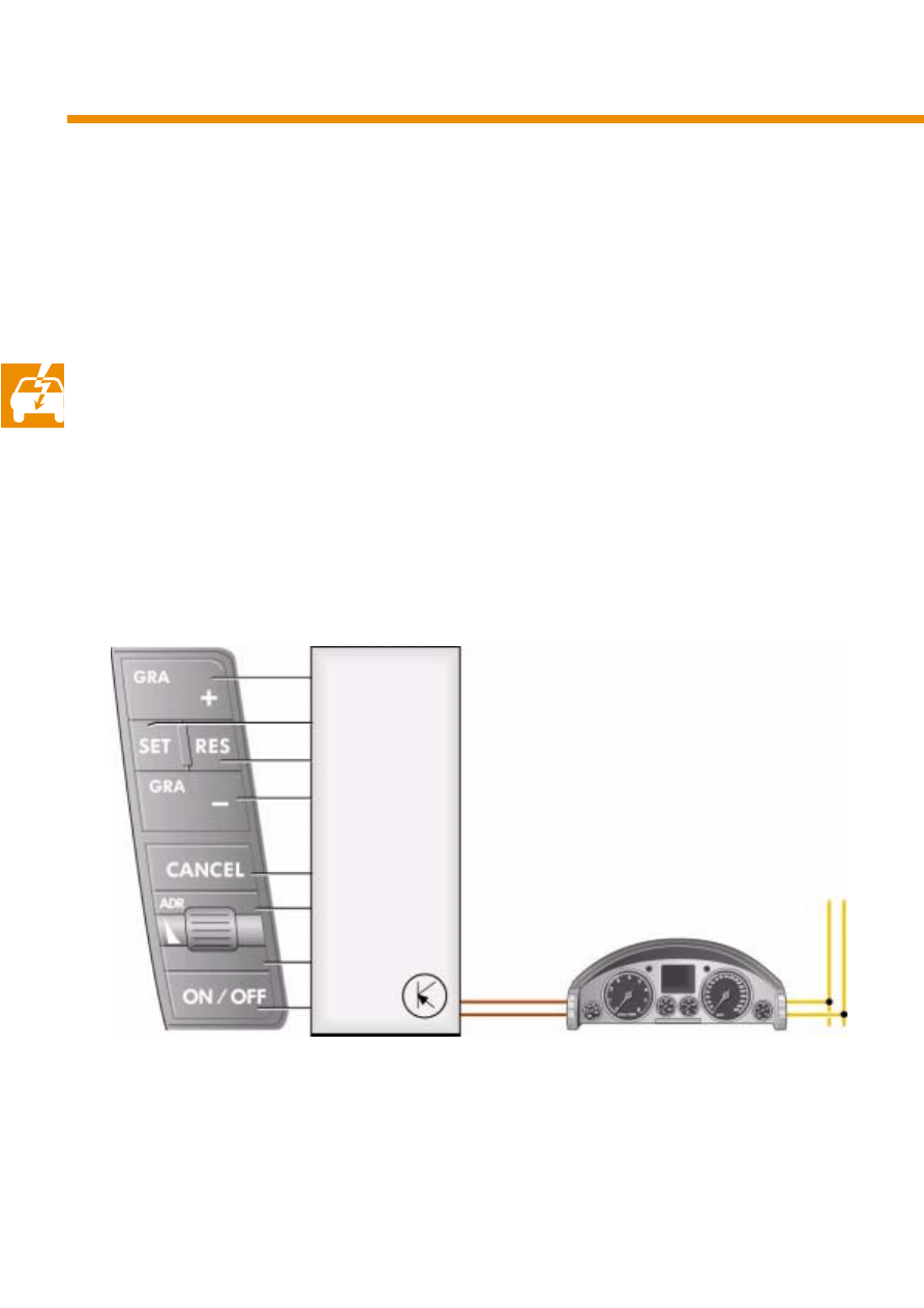
The APC system is mainly operated by means of
the left button cluster on the multi-function stee-
ring wheel. However, the brake and accelerator
pedals, as well as the gear selector lever posi-
tion, also have an influence on the APC system.
When the engine is started, the APC is always in
the "OFF" state and must be switched to
"Standby Mode" by pressing the ON/OFF but-
ton. The
desired speed
memory remains empty
and the following distance is set to the default
value of 1.4 s.
While driving (v > 30 kph), the actual speed
stored as a desired speed and the APC can be
activated by pressing the SET button. The desired
speed can be reduced in 1 kph increments to a
minimum value of 30 kph by repeatedly pressing
the SET button.
Pressing the CANCEL button switches the APC to
"Standby Mode" whilst retaining the desired
speed value in the memory.
S276_046
14
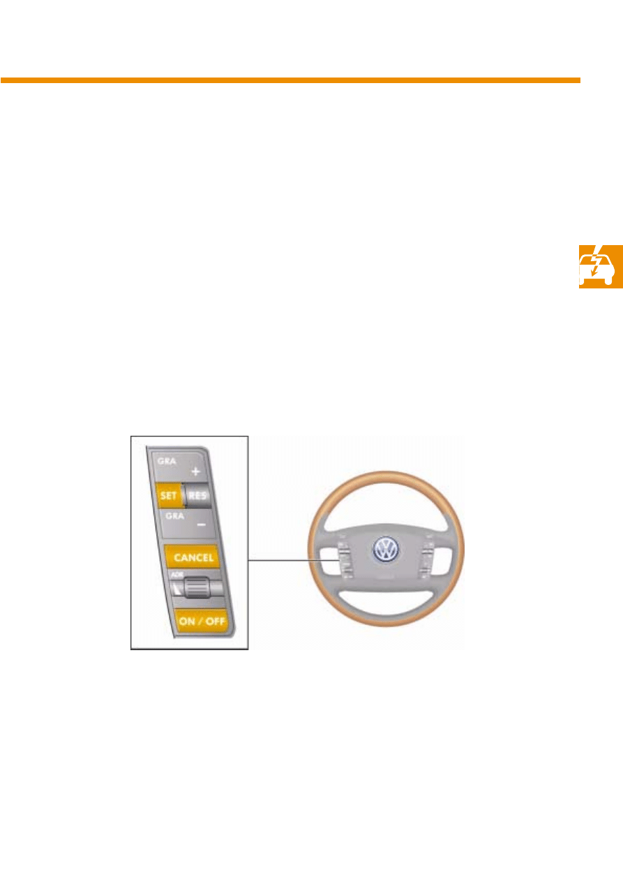
The APC can be reset to the preselected
desired
speed
by pressing the RES button. The desired
speed can be increased in 1 kph increments to a
maximum value of 180 kph by repeatedly pres-
sing the SET button. The desired speed can also
be increased or reduced in 10 kph increments by
pressing the "CCS+" or "CCS-" button.
The distance perceived by the driver to be a com-
fortable following distance to a vehicle ahead is
speed-dependent. Higher speeds require larger
distances between vehicles.
However, the
following time
which the vehicle
with APC system takes to cover the distance to the
vehicle ahead remains constant. The speed-
dependent following distance is also known as
the
time gap
.
The following time can be set to a default value
of 1.4 seconds by pressing the ON/OFF button
and adjusted in seven steps by means of a
thumbwheel to values ranging between 1 and
3.6 seconds.
Components of the APC system
S276_047
15
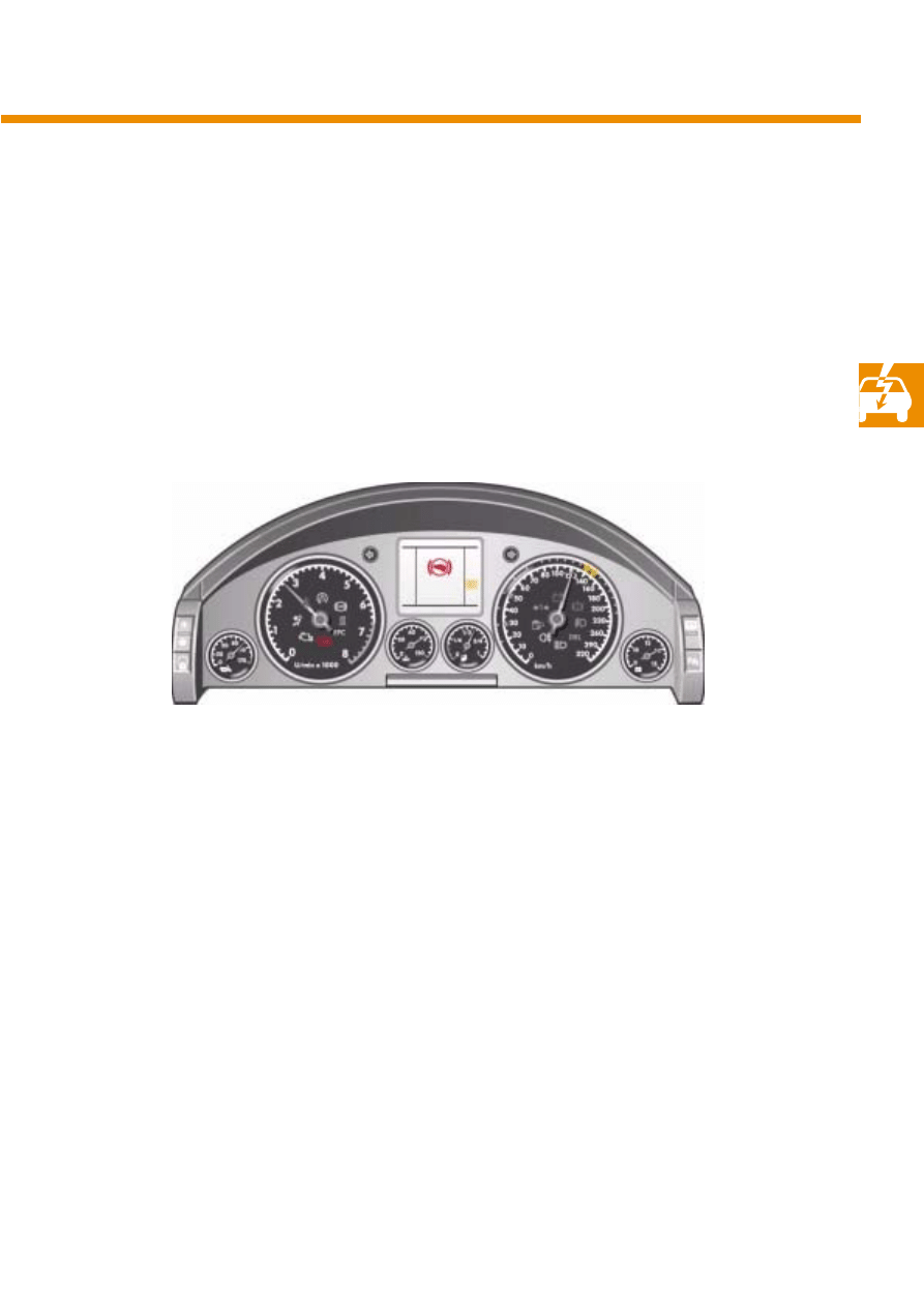
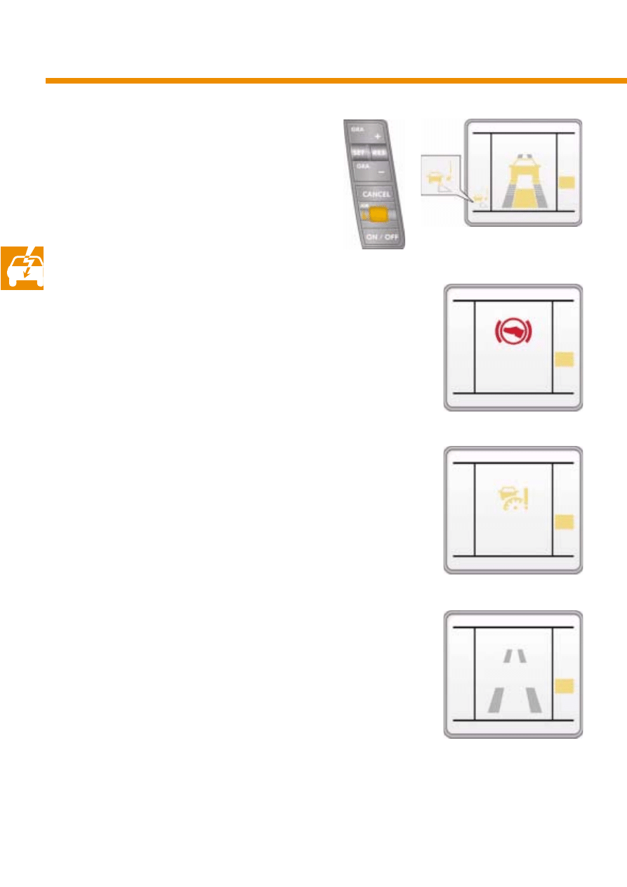
APC display in the dash panel insert
The driver receives information about the APC
system on several displays, some of which are
redundant
.
The LED ring around the speedometer and the
red symbol for the APC in the rev counter are
redundant and provide the minimum necessary
information to the driver in case the colour
screen is unavailable.
The set
desired speed
is indicated via the LED
ring in the speedometer.
The optical displays are supplemented by two
acoustic signals: a discrete gong and an aggres-
sive gong. The discrete gong sounds when the
APC is switched from the active state to "Standby
Mode" or "OFF state". The aggressive gong
sounds along with the red warning signal.
●
Large APC display at the centre of the
colour screen
●
Small APC display at the bottom left of the
colour screen
●
LED ring around the speedometer
●
Red symbol for APC "Apply brake"
in the rev counter
●
Two-stage acoustic signal
S276_051
A
A
A
AP
P
P
PP
P
P
PL
L
L
LY
Y
Y
Y
B
B
B
BR
R
R
RA
A
A
AK
K
K
KE
E
E
E
P
P
P
P
R
R
R
R
N
N
N
N
D
D
D
D3
3
3
3
S
S
S
S
4
4
4
41
1
1
12
2
2
2.
.
.
.3
3
3
3
k
k
k
km
m
m
m
1
1
1
12
2
2
2.
.
.
.3
3
3
3
o
o
o
o
C
C
C
C
1
1
1
12
2
2
23
3
3
34
4
4
45
5
5
56
6
6
6
k
k
k
km
m
m
m
16
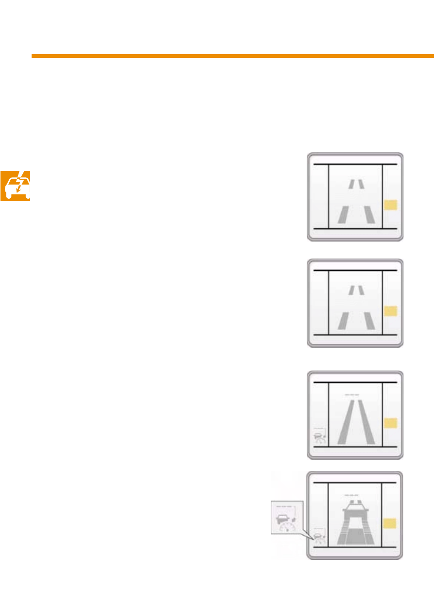
When the APC system is inactive, the display
"APC OFF" appears.
After the APC is switched on by pressing the
ON/OFF button, the message "APC IS STAR-
TING" appears for short period of time.
The APC now switches to "Standby Mode".
In this mode, the contents of the display are
represented in grey. The large display shows a
stylised lane, at the end of which the
desired
speed
is displayed.
In Cruise Control Mode (CCS Mode), no vehicle
ahead is detected and displayed.
If a
relevant
vehicle ahead of the car is detected,
it is also indicated.
The APC symbol represents the small display and
provides information on desired speed.
Components of the APC system
S276_066
S276_067
S276_064
A
A
A
AP
P
P
PC
C
C
C
O
O
O
OF
F
F
FF
F
F
F
P
P
P
P
R
R
R
R
N
N
N
N
D
D
D
D3
3
3
3
S
S
S
S
4
4
4
41
1
1
12
2
2
2.
.
.
.3
3
3
3
k
k
k
km
m
m
m
1
1
1
12
2
2
2.
.
.
.3
3
3
3
o
o
o
o
C
C
C
C
1
1
1
12
2
2
23
3
3
34
4
4
45
5
5
56
6
6
6
k
k
k
km
m
m
m
k
k
k
kp
p
p
ph
h
h
h
P
P
P
P
R
R
R
R
N
N
N
N
D
D
D
D3
3
3
3
S
S
S
S
4
4
4
41
1
1
12
2
2
2.
.
.
.3
3
3
3
k
k
k
km
m
m
m
1
1
1
12
2
2
2.
.
.
.3
3
3
3
o
o
o
o
C
C
C
C
1
1
1
12
2
2
23
3
3
34
4
4
45
5
5
56
6
6
6
k
k
k
km
m
m
m
P
P
P
P
R
R
R
R
N
N
N
N
D
D
D
D3
3
3
3
S
S
S
S
4
4
4
41
1
1
12
2
2
2.
.
.
.3
3
3
3
k
k
k
km
m
m
m
1
1
1
12
2
2
2.
.
.
.3
3
3
3
o
o
o
o
C
C
C
C
1
1
1
12
2
2
23
3
3
34
4
4
45
5
5
56
6
6
6
k
k
k
km
m
m
m
k
k
k
kp
p
p
ph
h
h
h
The large APC display shares the centre of the display with various Infotainment systems, i.e. it disap-
pears when other displays are active. To maintain information flow to the driver in this case, a small APC
display remains active at the bottom left of the display.
Passive display elements are coloured grey and active display elements are orange. Very important
information is displayed in red.
A
A
A
AP
P
P
PC
C
C
C
I
I
I
IS
S
S
S
S
S
S
ST
T
T
TA
A
A
AR
R
R
RT
T
T
TI
I
I
IN
N
N
NG
G
G
G
P
P
P
P
R
R
R
R
N
N
N
N
D
D
D
D3
3
3
3
S
S
S
S
4
4
4
41
1
1
12
2
2
2.
.
.
.3
3
3
3
k
k
k
km
m
m
m
1
1
1
12
2
2
2.
.
.
.3
3
3
3
o
o
o
o
C
C
C
C
1
1
1
12
2
2
23
3
3
34
4
4
45
5
5
56
6
6
6
k
k
k
km
m
m
m
S276_065
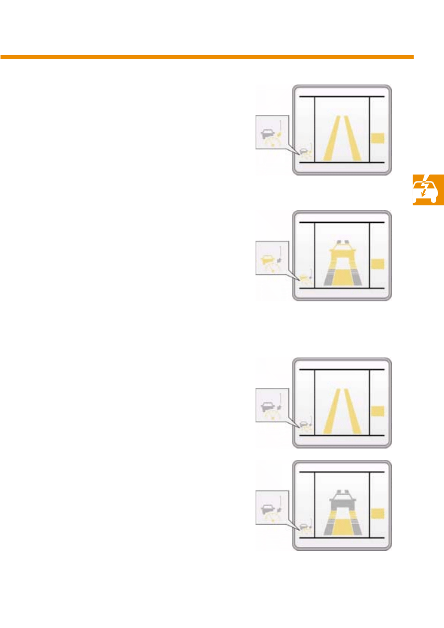
17
The APC is activated by pressing the SET button
or the RES button. The active display elements
are coloured orange.
If a
relevant
vehicle is detected, it appears in the
display. The colour of the kph display changes to
grey since the displayed speed no longer mat-
ches the actual speed.
The
time gap
(following distance) to the vehicle in
front is represented in seven steps. The time gap
actively set by the driver is represented in
orange. The centre bar indicates the vehicle's
position in relation to the vehicle ahead.
If the driver accelerates by pressing the accelera-
tor, the colour of the vehicle shown in the display
or, in CCS Mode, the colour of the
desired speed
changes from orange to grey.
S276_070
S276_071
S276_068
S276_069
1
1
1
16
6
6
60
0
0
0
k
k
k
kp
p
p
ph
h
h
h
P
P
P
P
R
R
R
R
N
N
N
N
D
D
D
D3
3
3
3
S
S
S
S
4
4
4
41
1
1
12
2
2
2.
.
.
.3
3
3
3
k
k
k
km
m
m
m
1
1
1
12
2
2
2.
.
.
.3
3
3
3
o
o
o
o
C
C
C
C
1
1
1
12
2
2
23
3
3
34
4
4
45
5
5
56
6
6
6
k
k
k
km
m
m
m
1
1
1
16
6
6
60
0
0
0
1
1
1
16
6
6
60
0
0
0
1
1
1
16
6
6
60
0
0
0
k
k
k
kp
p
p
ph
h
h
h
P
P
P
P
R
R
R
R
N
N
N
N
D
D
D
D3
3
3
3
S
S
S
S
4
4
4
41
1
1
12
2
2
2.
.
.
.3
3
3
3
k
k
k
km
m
m
m
1
1
1
12
2
2
2.
.
.
.3
3
3
3
o
o
o
o
C
C
C
C
1
1
1
12
2
2
23
3
3
34
4
4
45
5
5
56
6
6
6
k
k
k
km
m
m
m
1
1
1
16
6
6
60
0
0
0
1
1
1
16
6
6
60
0
0
0
1
1
1
16
6
6
60
0
0
0
k
k
k
kp
p
p
ph
h
h
h
P
P
P
P
R
R
R
R
N
N
N
N
D
D
D
D3
3
3
3
S
S
S
S
4
4
4
41
1
1
12
2
2
2.
.
.
.3
3
3
3
k
k
k
km
m
m
m
1
1
1
12
2
2
2.
.
.
.3
3
3
3
o
o
o
o
C
C
C
C
1
1
1
12
2
2
23
3
3
34
4
4
45
5
5
56
6
6
6
k
k
k
km
m
m
m
1
1
1
16
6
6
60
0
0
0
1
1
1
16
6
6
60
0
0
0
1
1
1
16
6
6
60
0
0
0
k
k
k
kp
p
p
ph
h
h
h
P
P
P
P
R
R
R
R
N
N
N
N
D
D
D
D3
3
3
3
S
S
S
S
4
4
4
41
1
1
12
2
2
2.
.
.
.3
3
3
3
k
k
k
km
m
m
m
1
1
1
12
2
2
2.
.
.
.3
3
3
3
o
o
o
o
C
C
C
C
1
1
1
12
2
2
23
3
3
34
4
4
45
5
5
56
6
6
6
k
k
k
km
m
m
m
1
1
1
16
6
6
60
0
0
0
1
1
1
16
6
6
60
0
0
0
18
If the driver changes the
time gap (following
distance) by turning the thumbwheel, the display
changes for several seconds. The time gap is now
as indicated in the small display in the form of
several bars and in digits in the
desired speed
display field.
The red warning lights up together with the red
symbol for APC "Apply brake" in the rev counter
and prompts the driver to take control of the
vehicle by applying the brake. This is necessary
when the braking performance of the APC is
insufficient.
This is not displayed if the sensor is soiled. Howe-
ver, the system remains active.
If the internal diagnostics detect a fault, it is also
displayed. The system switches to "Standby
Mode". After several seconds, the fault message
becomes passive.
Components of the APC system
S276_074
S276_075
S276_072
S276_058
S276_063
A
A
A
AP
P
P
PP
P
P
PL
L
L
LY
Y
Y
Y
B
B
B
BR
R
R
RA
A
A
AK
K
K
KE
E
E
E
P
P
P
P
R
R
R
R
N
N
N
N
D
D
D
D3
3
3
3
S
S
S
S
4
4
4
41
1
1
12
2
2
2.
.
.
.3
3
3
3
k
k
k
km
m
m
m
1
1
1
12
2
2
2.
.
.
.3
3
3
3
o
o
o
o
C
C
C
C
1
1
1
12
2
2
23
3
3
34
4
4
45
5
5
56
6
6
6
k
k
k
km
m
m
m
A
A
A
AP
P
P
PC
C
C
C
S
S
S
SE
E
E
EN
N
N
NS
S
S
SO
O
O
OR
R
R
R
S
S
S
SO
O
O
OI
I
I
IL
L
L
LE
E
E
ED
D
D
D
P
P
P
P
R
R
R
R
N
N
N
N
D
D
D
D3
3
3
3
S
S
S
S
4
4
4
41
1
1
12
2
2
2.
.
.
.3
3
3
3
k
k
k
km
m
m
m
1
1
1
12
2
2
2.
.
.
.3
3
3
3
o
o
o
o
C
C
C
C
1
1
1
12
2
2
23
3
3
34
4
4
45
5
5
56
6
6
6
k
k
k
km
m
m
m
A
A
A
AP
P
P
PC
C
C
C
D
D
D
DE
E
E
EF
F
F
FE
E
E
EC
C
C
CT
T
T
TI
I
I
IV
V
V
VE
E
E
E
P
P
P
P
R
R
R
R
N
N
N
N
D
D
D
D3
3
3
3
S
S
S
S
4
4
4
41
1
1
12
2
2
2.
.
.
.3
3
3
3
k
k
k
km
m
m
m
1
1
1
12
2
2
2.
.
.
.3
3
3
3
o
o
o
o
C
C
C
C
1
1
1
12
2
2
23
3
3
34
4
4
45
5
5
56
6
6
6
k
k
k
km
m
m
m
1
1
1
16
6
6
60
0
0
0
k
k
k
kp
p
p
ph
h
h
h
P
P
P
P
R
R
R
R
N
N
N
N
D
D
D
D3
3
3
3
S
S
S
S
4
4
4
41
1
1
12
2
2
2.
.
.
.3
3
3
3
k
k
k
km
m
m
m
1
1
1
12
2
2
2.
.
.
.3
3
3
3
o
o
o
o
C
C
C
C
1
1
1
12
2
2
23
3
3
34
4
4
45
5
5
56
6
6
6
k
k
k
km
m
m
m
2
2
2
2
2
2
2
2
19
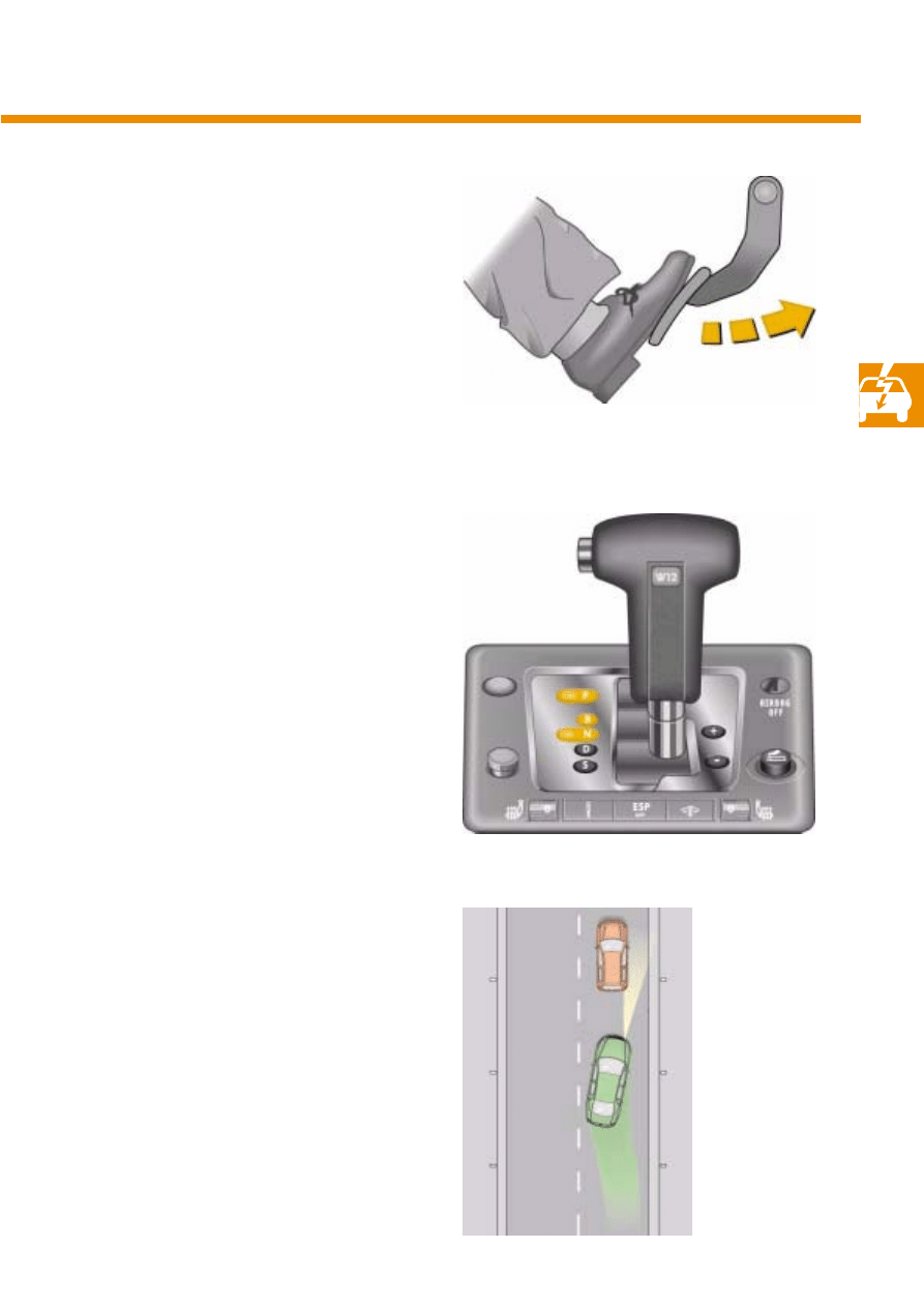
Accelerator, brake pedal
and selector lever
When the APC system is active, the APC can be
deactivated and the vehicle accelerated by pres-
sing the accelerator pedal. If the driver eases his
foot off the accelerator pedal, the APC continues
operation and decelerates the vehicle to the
desi-
red speed or to the current time gap (following
distance).
Pressing the brake pedal deactivates the APC
immediately whilst the desired speed is retained
in the memory ("Standby Mode").
If the selector lever is moved from "D" position to
"N", "R" or "P" position, the APC is deactivated.
The APC remains active in all other selector lever
positions.
If the min. speed of 30 kph is undershot or the
max. speed of 180 kph is exceeded, the APC is
deactivated.
The APC system is also deactivated by interven-
tion in the brake system by ESP, TCS, EBC or ABS,
although APC braking operations in progress are
completed.
Dynamic intervention is independent of any APC
braking operations.
S276_048
S276_049
S276_050
20
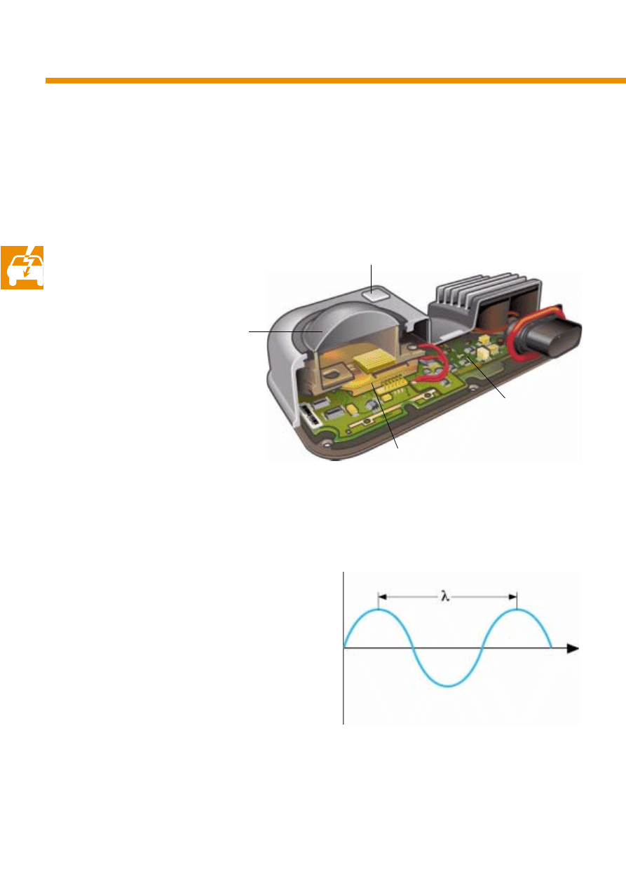
S276_055
Alignment mirror
Lens
Evaluation electronics
Transceiver unit
Proximity control sender, right
G 259
In the APC system, the distance is measured by a
sender based on
millimetre wave radar techno-
logy. The APC system also measures the distance
to several objects in the field of vision and the
relative speed along the longitudinal axis of the
vehicle. From the measured values, the angular
deviation
(azimuth angle) from the centre line of
the field of vision is calculated for each object.
The radar system uses electromagnetic waves
which propagate at the speed of light
c.
A wave of frequency
f requires a wavelength of
λ
for a wave train.
If the transmit frequency of the APC sensor is
f=76.5GHz, the wavelength is
λ=3.92mm.
Waves within a frequency range from approx.
30GHz to approx.150GHz are described as milli-
metre waves.
Components of the APC system
S276_045
Distance
21
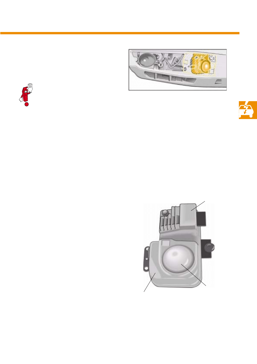
Transmit frequency
76.5GHz
Optical range
150m
Horizontal angle of vision
12°
Vertical angle of vision
4°
Speed measuring range
± 180kph
S276_003
Millimetre wave part
Processor part
Lens
S276_010
The sender is fitted behind a plastic cover in the
bumper. The lens which emits the beam is easily
recognisable.
The sender's field of vision can be compared to
the illumination zone of a highly focused head-
light. As with the headlight, the centre line of the
sensor's field of vision must be exactly aligned in
the direction of travel.
A processor with high computing power is inte-
grated in the sender housing. The following addi-
tional calculations are performed:
●
Lane forecast
●
Selection of the
relevant object
●
Distance and speed control
●
Activation of the engine control unit,
brake servo and dash panel insert
●
Self-diagnosis
The cover may only be painted in a milli-
metre wave permeable colour. It may not
be recoated on the inside or outside, and
may not be covered. In addition, the
cover must be kept free of dirt as well as
ice and snow.
22
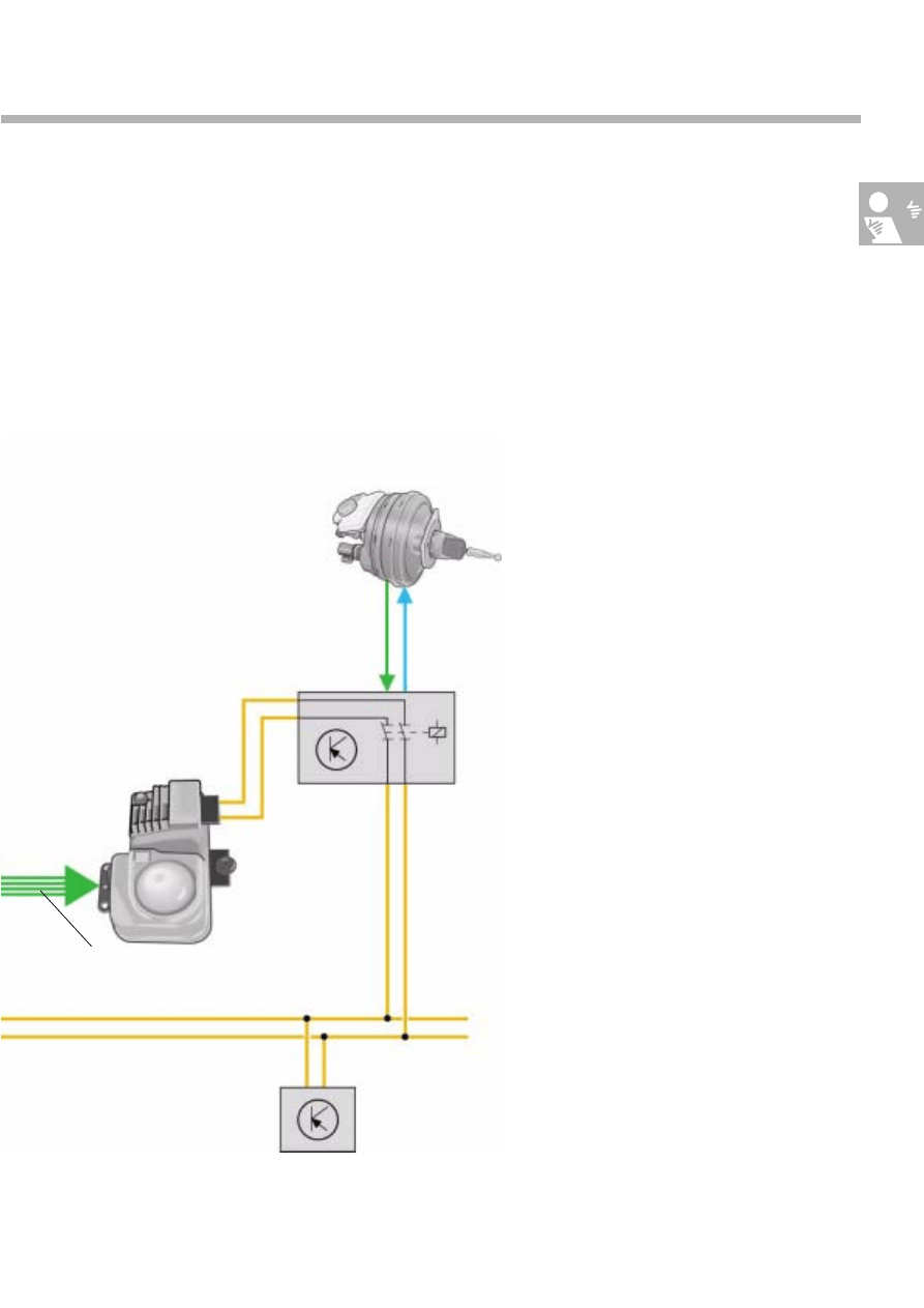
Brake servo control unit
Fitting location
The control unit of the
electronic brake servo is
located in the plenum chamber on the right-hand
side and is only accessible by removing the coo-
lant expansion tank.
The brake servo control unit controls brake pres-
sure build-up and relief.
For reasons of anti-theft security, the bus inter-
face of the proximity control sender cannot be
deactivated directly. Instead it can only be swit-
ched off via the brake servo control unit.
Components of the APC system
S276_012
S276_059
Drive train CAN
databus
Brake servo control unit
J 539
23
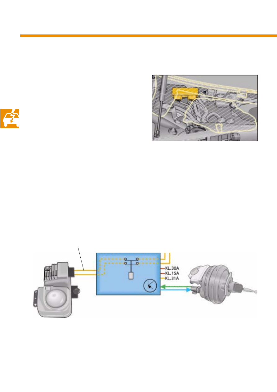
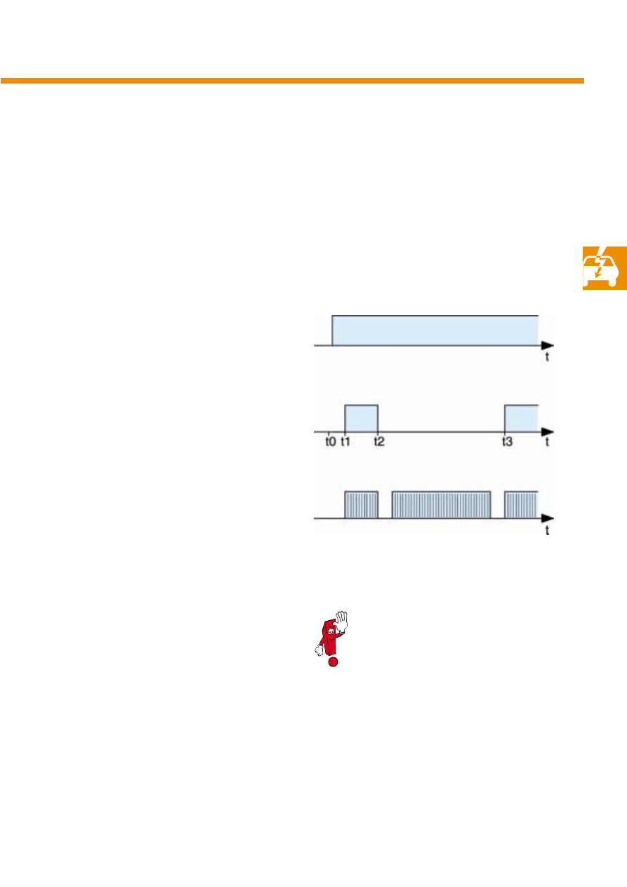
Anti-theft alarm system
As the proximity control sender with its CAN
databus connection is mounted on the exterior of
the vehicle, it would be possible to interrogate
the immobiliser code. To avoid impairing the
immobiliser function, a special switch-on proce-
dure is performed by means of the CAN databus
relay in the brake servo control unit.
t0:
●
Terminal 15 is connected.
●
Start of brake servo control unit
initialisation.
t1:
●
End of brake servo control unit
initialisation.
●
The bus relay is closed.
●
The proximity control sender transfers
a system message via the CAN databus.
t2:
●
The brake servo control unit indicates "Bus
open" to the proximity control sender to sup-
press "BUS-OFF" of the CAN controller in the
proximity control sender.
●
The brake servo control unit opens the bus
relay.
●
The engine electronics interrogate the immobi-
liser code on the bus and communicate with
the immobiliser.
t3:
●
The bus relay is closed.
●
Normal operation commences.
S276_029
Terminal 15
Bus relay
Drive train CAN databus
closed
As the bus relay is open while the immo-
biliser is initialising, the immobiliser code
cannot be interrogated via the proximity
control sender.
open
24
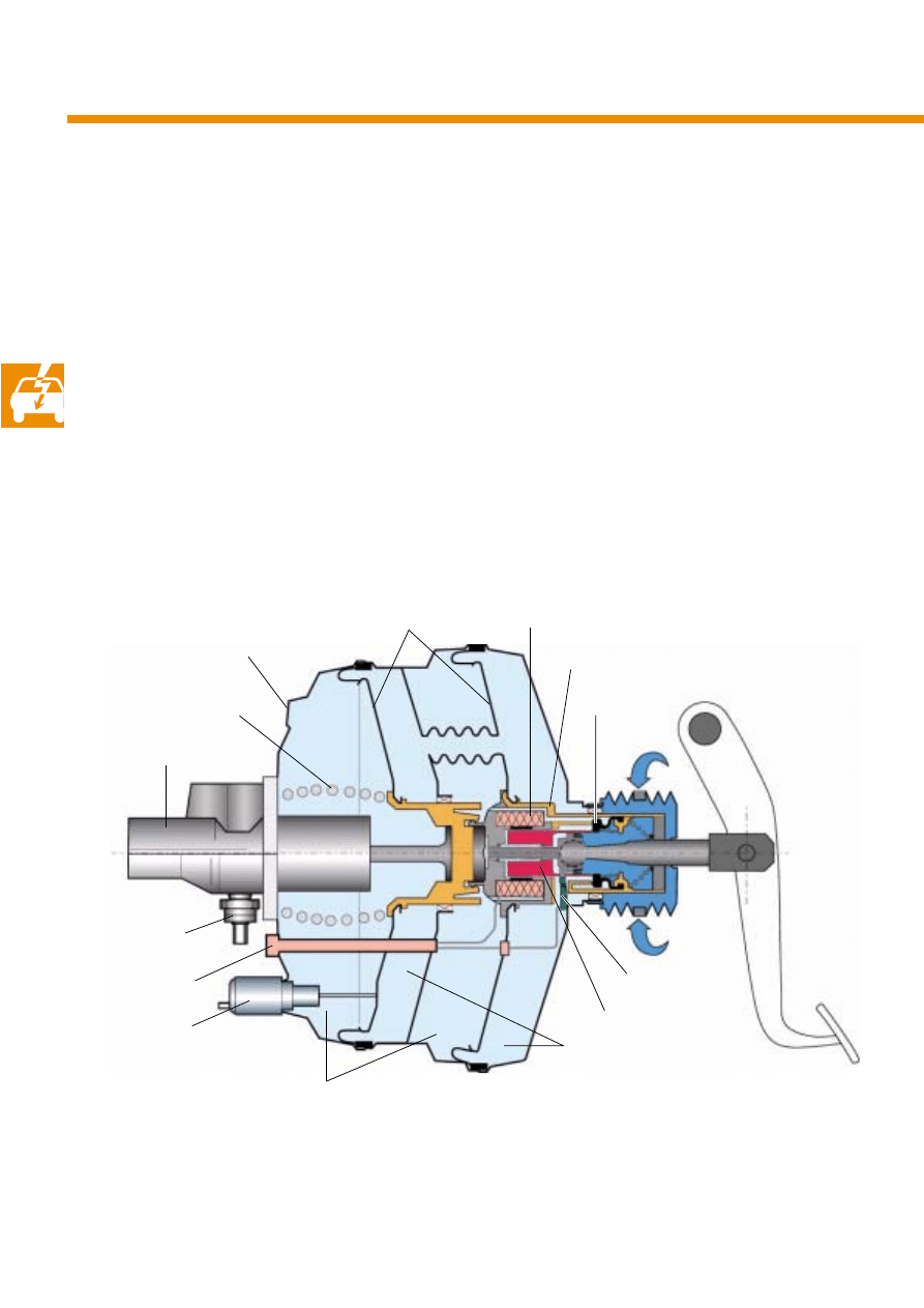
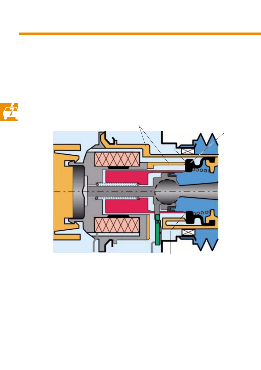
Electronic brake servo (EBS)
The
electronic brake servo in the APC system has
the task of activating the brake to control the
distance to a vehicle in front. Special value is
attached to soft, comfortable braking.
A
proportional solenoid (adjustment proportional
to exciter current) was integrated in the tandem
servo together with the membrane position sen-
sor (stepless potentiometer) and
the release
switch.
To achieve high braking quality, the brake pres-
sure is controlled by measuring the brake pres-
sure at the master brake cylinder by means of a
pressure ender. At the start of the control process,
the pressure controller is subjected to a mem-
brane position control.
During an electrically activated braking opera-
tion, the brake pedal moves accordingly.
Components of the APC system
Micro master cylinder
Vacuum connection
Membrane spring
Connector
Membrane position sensor
Vacuum chamber
S276_042
Magnet armature
Release switch
Atmosphere
Disc seal
Valve body
Working chamber
Membrane disc
Brake
pressure sender
Proportional magnet
25
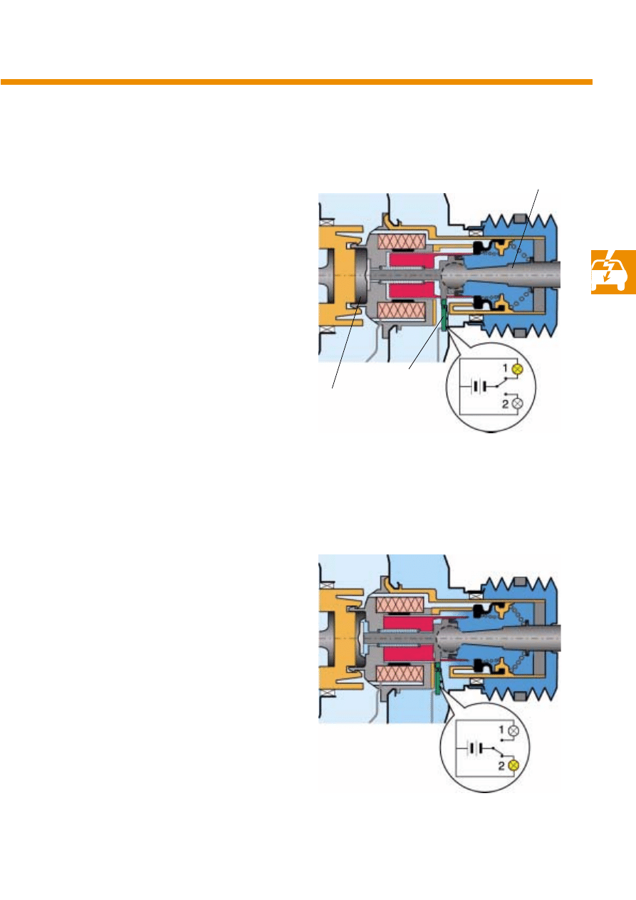
Release switch
The
release switch helps to distinguish whether
the brake was electrically activated. Since the
switch is a safety-critical component, it is desi-
gned as both an NC contact and an NO contact
(two-way switch) in order to determine the rest
and working positions.
In the rest position or when the brake servo is
electrically actuated, no force is applied to the
elastic reaction disc via the actuating rod, with
the result that the reaction disc is pressure-relie-
ved. In this position, the release switch rests
against the housing of the brake servo and closes
electric circuit 1.
If the driver applies the brake, pressure is app-
lied to the reaction disc via the actuating rod. The
reaction disc is compressed. The release switch
rises from the brake servo housing. Electric circuit
2 is closed.
S276_044
S276_062
Actuating rod
Release switch
Reaction disc
26
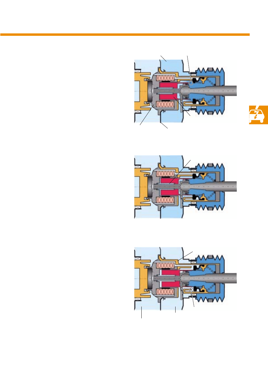
Initial position
The amplifier is in its starting position, the
vacuum has built up and the
proportional
magnet is de-energised.
The sealing edge of the solenoid armature acts
as an inlet valve. The sealing edge of the valve
body acts as an exhaust valve.
Both valves open and close when the sealing
edge lifts off or rests against the disc seal.
The function of the
electronic brake servo is defi-
ned by the sealing edge, which acts as a valve,
and the disc seal. The pressure in the working
chamber is dependent on the position of the val-
ves.
Components of the APC system
S276_043
Valve body
Sealing edge (valve body)
Sealing edge (magnet armature)
Disc seal
27
Pressure build-up
When pressure build-up is electrically activated,
the
proportional magnet is energised. The air
gap between the
stator and the magnet arma-
ture becomes smaller. The inlet valve opens, and
atmospheric air flows into the working chamber.
The membrane disc compresses the membrane
spring. Up to approx. 30 % of the brake pressure
can be achieved.
Maintaining the pressure
To maintain pressure, the current following
through the solenoid is reduced. The armature
spring pushes the stator and the magnet arma-
ture apart, thus closing the inlet valve.
The partial vacuum in the working chamber defi-
nes the position of the membrane disc.
Pressure relief
If the solenoid is de-energised, the armature
pushes the disc seal back over the sealing edge
of the inlet valve. The exhaust valve is opened.
The air in the working chamber flows into the
vacuum chamber and is drawn off through the
engine. The membrane spring relaxes.
S276_031
S276_032
S276_033
Working chamber
Magnet armature
Stator
Armature spring
Valve body
Vacuum chamber
Inlet valve
Membrane disc
Working chamber
Exhaust valve
28
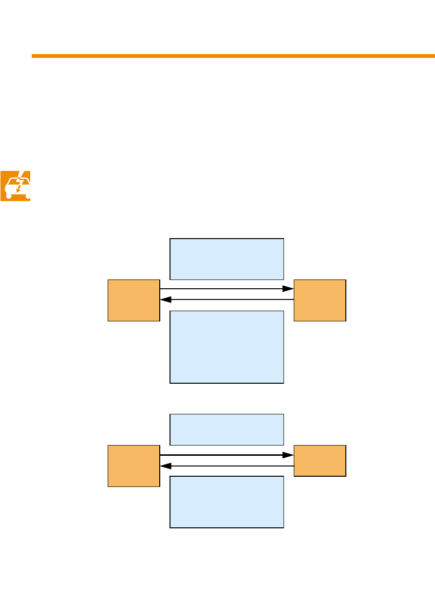
Data flow in the CAN network
The proximity control sender is interfaced to the
drive train CAN databus via the bus relay in the
brake servo control unit.
The proximity control sender communicates with
the control units:
●
Brake servo control unit
●
Engine control unit
●
Dash panel insert
●
Steering column electronics control unit
●
Automatic gearbox control unit
●
ABS with EDL control unit
Components of the APC system
Brake pressure request
Request brake preset
Interrogate bus relay
Proximity con-
trol sender
Brake servo
control unit
Driver applies brake
Release switch
plausible/
implausible
Bus relay open/closed
Status
of electronic brake servo
Torque request
APC status
Engine control
unit
Engine torque
Accelerator pedal angle
Driver takes control of accelera-
tor pedal
Emergency running/ready
Proximity con-
trol sender
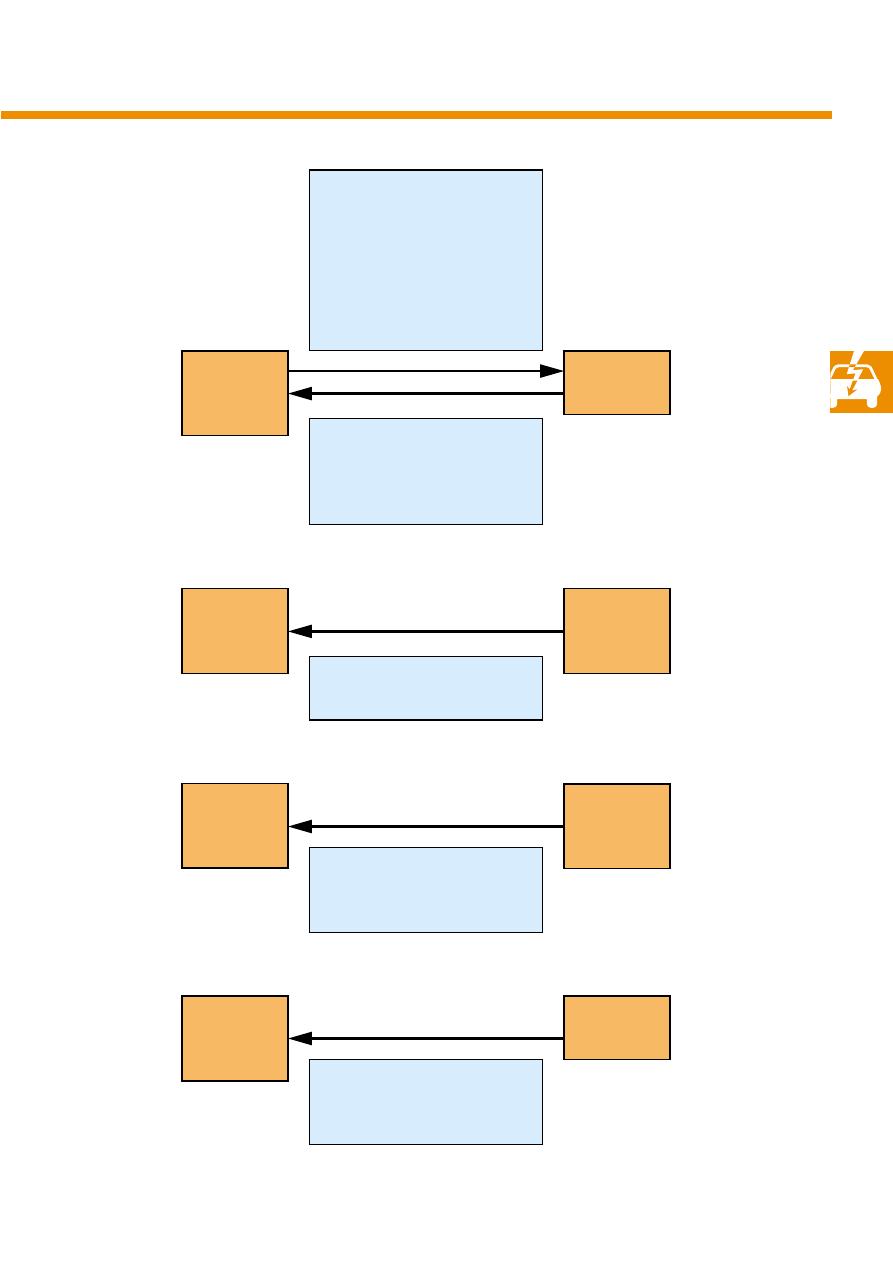
29
APC status
Desired speed
Set
time gap
Object detected
Current distance
System limits reached
Activation of gongs 1 and 2
Sensor blind
APC display error
Speed displayed on speedometer
Display time gap
Steering wheel control inputs
Steering angle
Current gear
Selector lever position
Emergency running
Proximity con-
trol sender
Dash panel
insert
ABS, TCS, ESP intervention
Yaw velocity
Brake pressure
Automatic
gearbox con-
trol unit
ABS with EDL
control unit
Proximity con-
trol sender
Proximity con-
trol sender
Proximity con-
trol sender
Steering
column electro-
nics control unit
30
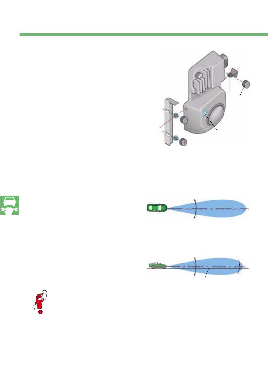
Adjusting the proximity control sen-
der
The proximity control sender is adjusted by
means of two adjusting screws (S1 and S2) loca-
ted on the left-hand side of the sender. The screw
on the right-hand side serves as a clamping
screw to of a ball joint as a third bearing point
for the sender.
The adjusting screws have six detent positions
per turn.
Turning adjusting screws S1 and S2 evenly swivels
the sender into the horizontal plane. Turning
adjusting screw S2 swivels the sender into the
vertical plane.
Align the centre line of the sender
detection field
both in the horizontal and vertical planes. In the
horizontal plane, align the centre line (
radar
axis) in parallel to the driving axis. In the vertical
plane, set an inclination of 1°.
Service
S276_038
S276_052
Horizontal detection field
Horizontal adjustment direction
Vertical adjustment direction
Radar axis
S276_053
Welded-on
steel bracket
Driving axis
Radar axis
Road
Horizontal
Clamping
screw
S1
S2
1°
Alignment mirror
Horizontal plane
Vertical plane
Mechanical adjustment of the proximity
control sender is absolutely necessary
after:
●
adjustments to the suspension
●
replacement of senders or cross-mem-
bers
●
the cross-member is subjected to
mechanical stress (collision)
31
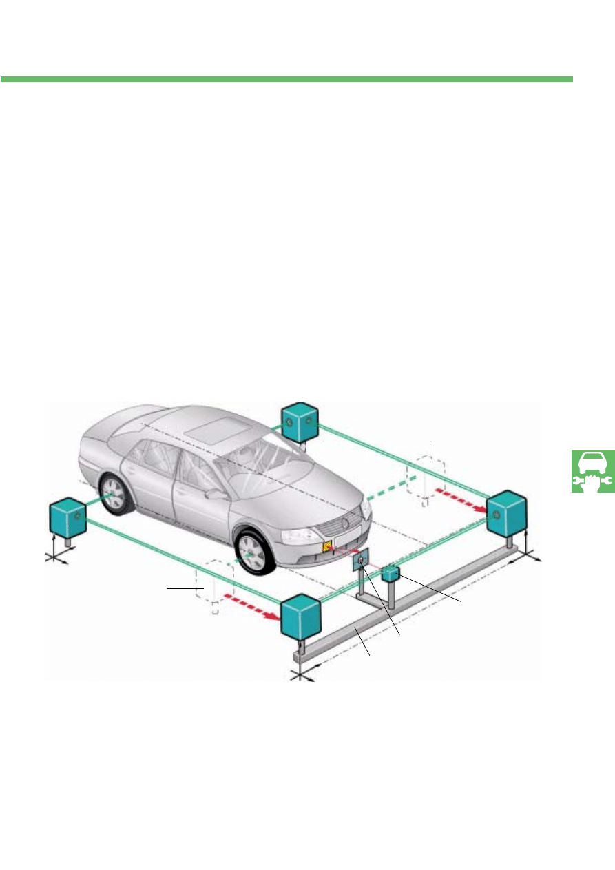
Measuring method
The
driving axis is determined using a wheel ali-
gnment test stand and the APC adjustment
device VAS 6041. A laser pointer is attached to
the VAS 6041 level with the proximity control sen-
der. A target disc is positioned between the laser
pointer and the proximity control sender. The tar-
get disc has a centre hole through which the
beam of the laser pointer impinges on the align-
ment mirror of the proximity control sender.
When the suspension is adjusted, the measuring
equipment of the test bench is aligned in parallel
with the driving axis. The APC adjustment device
is aligned with the driving axis using the front
axle transducers together with the remaining
transducers on the rear axle.
Front axle transducer
S276_013
Laser pointer
APC adjustment device
Front axle
transducer
Schematic diagram
Target disc
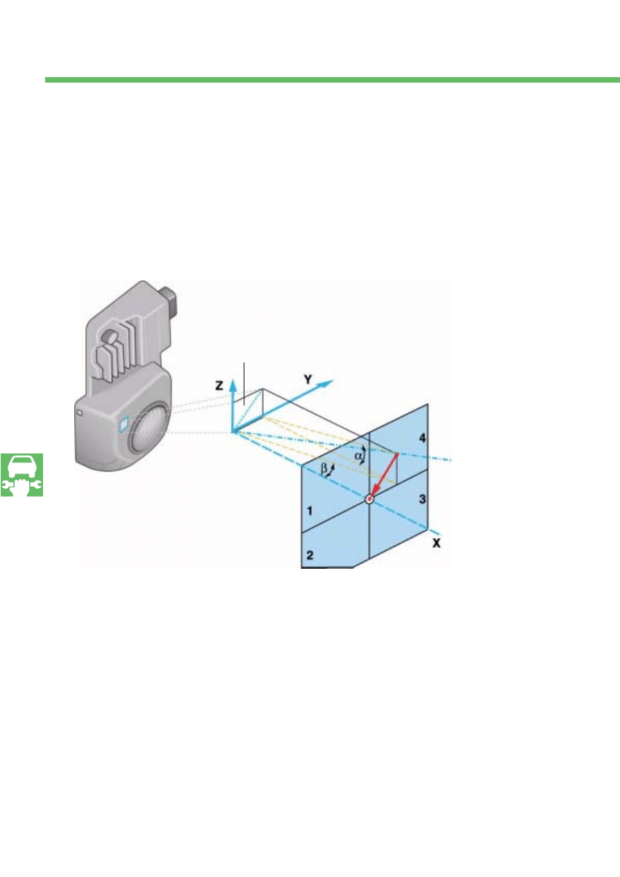
32
In the case of a perfectly aligned proximity con-
trol sender, the laser beam should be reflected
through the centre hole in the target disc. If the
APC is unadjusted, the laser beam impinges on
the target disc in one of the
4-segment quadrants. The sender must be ali-
gned by means of the adjusting screws such that
the reflected laser beam passes through the cen-
tre hole in the target disc.
In the horizontal plane, a high degree of adjust-
ment accuracy is required. Only a rough adjust-
ment can be made by means of the adjusting
screws.
Fine adjustment is carried out electronically
inside the sender while driving.
Service
S276_014
Longitudinal axis of vehicle
= Radar normal
Mirror normal
Adjustment:
α: rotation by means of S2
β: rotation by means of S1 and S2
Alignment mirror
33
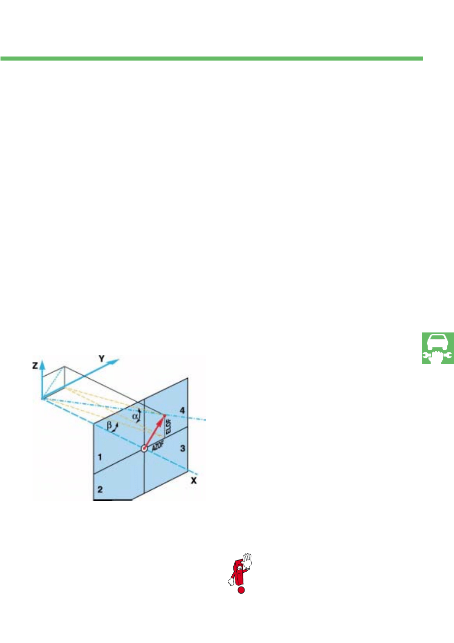
Correcting an indication error
The mirror normal and the centre line of the
detection field (radar normal) do not match up
for production reasons. The
indication error in
the horizontal and vertical planes is measured at
the factory and stored in the sender memory as a
correction value. The indication error is specified
as a number of detents of the adjusting screw.
The correction values can be exported with the
VAS tester.
Once adjusted by the correction values, the laser
beam moves from the centre into one of the qua-
drants. To check that the adjusting screws have
been turned in the correct direction, the target
quadrant is also stored in the sender memory.
Data block 06
●
Meas.
value 2: AZOF Mirror indication error
in the horizontal plane
(AZOF = azimuth offset)
●
Meas.
value 3: ELOF mirror indication error
in the vertical plane
(ELOF = Elevation Offset)
S276_015
Longitudinal axis of vehicle
= Radar normal
Mirror normal
Adjustment:
α: rotation by means of S2
β: rotation by means of S1 and S2
You will find details in the associated
Workshop Manual.

34
Release switch in the brake servo
The switch must reliably recognise driver brake
actuation in order to switch the APC system to
"Standby Mode". For this purpose, the switch is
designed as a two-pole two-way switch.
Coil spring in the steering wheel
Steering wheel button information is transferred
via a serial bus routed via the coil spring of the
steering wheel. To ensure that the APC is swit-
ched off by the ON/OFF button in the event of a
bus failure, this key information is transferred
redundantly via a separate wire of the coil
spring.
Redundant display
If the display fails, the red symbol for APC in the
rev counter and the LED ring around the speedo-
meter provide the driver with the minimum neces-
sary information about the APC system.
Coupling the APC system to the ESP function
The APC is switched off or cannot be activated
when the ESP function is not available. If ESP is
activated during an APC braking operation or if
it fails, the APC braking operation is nevertheless
completed.
CAN databus disconnect
Since the proximity control sender must be moun-
ted in an exposed position at the front end of the
vehicle, there is a danger that it may receive
damage. To prevent the vehicle from breaking
down if the drive train CAN databus fails as a
result of bus blockade by the proximity control
sender, the sender is disconnected via the bus
relay in the brake servo control unit.
Service
System safety
A series of measures have been taken to prevent a faulty APC system from posing a danger to other road
users or resulting in a breakdown.
The most important measures are briefly explained below.
35
Diagnostics
The proximity control sender and the brake servo
control unit continuously test for proper
functioning. Any faults they detect are saved to
the fault memory.
The fault memories can be read out and guided
fault-finding can be performed by means of the
Vehicle Diagnostic, Testing and Information
System VAS 5051. You will find detailed informa-
tion in the associated Workshop Manual.
S276_039
S276_057

36
Azimuth angle
⇒ Reflection angle
Desired speed
The speed selected by the driver in CCS mode.
In APC mode, the actual speed is less than the
desired speed.
Detection field
⇒ Field of vision of sensor
Driver assistance system
Driver assistance systems are systems which sup-
port the driver however, without relieving him of
his responsibility to guide the vehicle safely.
Driving axis
Direction of movement of the vehicle with the
steering wheel in the straight ahead position.
Electronic brake servo
The electronic brake servo is a pneumatic brake
servo which can operate the brake by means of
an electromagnetic valve. A dedicated electronic
control unit ensures precise brake pressure appli-
cation.
Elevation angle
Vertical reflection angle
Field of vision of sensor
The region in front of the APC vehicle in which
vehicle and obstacles are detected. Comparable
with the illumination zone of a headlight (also
referred to as detection field).
Following time
The road speed-dependent distance to a vehicle
in front (also referred to as time gap).
Gateway
Electronic circuit or circuit component which faci-
litates data exchange between various data
buses.
Indication error
Angular error in relation to the ideal direction.
Lane forecast
The APC system should only respond to vehicles
driving ahead of the vehicle in the same lane.
This requires a lane forecast. The system calcula-
tes the lane ahead from the measured variables
wheel speeds, yaw rate and steering wheel
angle.
Millimetre waves
Electromagnetic waves in the frequency range
from approx. 30 to approx. 150GHz. The limits
are fuzzy and are referred to as millimetre waves
since their wavelength is in the millimetre range.
Glossary

37
Mirror normal
Line vertical to the surface of the mirror.
Proportional magnet
Solenoid whose armature length is proportional
to the coil current in the design range.
Proximity controller
The proximity controller in the APC system calcu-
lates the necessary engine torque or braking tor-
que from the measured variables distance and
relative speed to maintain the adjusted following
time to a vehicle driving in front.
Radar axis
Axis of symmetry of the radar detection field.
Redundant
Components or signals for increasing fail safety.
Reflection angle
Horizontal angular deviation of an object in rela-
tion to the radar centre line.
Release switch
Two-way switch integrated in the electronic brake
servo to detect brake application by the driver
and initiate the APC brake.
Relevant object
An object that the proximity controller in the APC
system uses for proximity control based on
distance and relative speed.
Stator
Stators and armatures form the magnetic circuit
of a solenoid whereby the stator is the stationary
part and the armature is the moving part.
Steering column electronics control unit
The steering column electronics control unit com-
prises the steering column switch and sends stee-
ring wheel button information to the convenience
CAN databus. The information provided by the
steering angle sensor is sent to the drive train
CAN databus.
Time gap
⇒ Following time

38
1. How does the APC function as a driver assi-
stance system?
a) It maintains the margin of safety to the
vehicle ahead if necessary by means of an
emergency braking operation.
b) It allows the driver to drift along comfor-
tably in the flowing traffic.
c) It relieves the driver on motorways.
2. Where does it make sense to use the APC?
a) On twisting hilly routes.
b) In heavy urban traffic.
c) On well-developed country roads with
large curve radii > 500m.
d) On motorways.
3. What measured variables does the proxi-
mity control sender determine?
a) The distance to other road users in front.
b) The time gap.
c) The azimuth angle to other road users in
front.
d) The desired speed.
e) The vehicle's speed relative to other road
users in front.
4. From what variables is the lane forecast
calculated?
a) The yaw rate measured in the ESP.
b) The distance to a vehicle in front.
c) Steering wheel angle.
d) Wheel speeds.
5. What are sensors used to ensure the high
braking quality of the electronic brake
servo?
a) The brake pressure sender G 201.
b) The release switch.
c) The membrane position sensor.
6. When is it necessary to readjust the proxi-
mity control sender?
a) After replacing the sender or
cross-member.
b) After minor damage to the rear end.
c) After adjusting the suspension.
Test your knowledge

39
7. When is adjustment of the proximity control
sender completed?
a) When the laser beam which passes
through the centre hole on the target disc is
reflected by the APC adjustment device.
b) When the adjusting screws are tightened
as far as the stop.
c) When the laser beam impinges on the spe-
cified quadrant after turning the adjusting
screws according to the values in data
block 06. Provided that the adjustment pro-
cedure begins in the position in which the
laser beam passing through the centre
hole on the target disc is reflected by the
APC adjustment device.
8. What is the function of the bus relay?
a) It replaces the gateway and connects the
convenience CAN bus to the drive train
CAN bus.
b) The solenoid valve in the electronic brake
servo is activated via this relay.
c) It helps to preserve theft protection by pre-
venting the immobiliser code from being
interrogated at the proximity control sen-
der.
d) Vehicle availability increases because a
defective CAN databus of the proximity
control sender does not the impair the
drive train CAN bus.
Solutions:
1. b, c2. c
, d3. a
, c
, e4. a
, c
, d5. a
, c6. a
, c7
. c
8. c, d
For internal use only. © VOLKSWAGEN AG, Wolfsburg
All rights reserved. Technical specifications subject to change without notice.
240.2810.95.20 Technical status: 02/02
❀
This paper is produced from
non-chlorine-bleached pulp.
2
2
2
2777766
6
6
Wyszukiwarka
Podobne podstrony:
Self Study Programme 280 Phaeton auxiliary heater top c and top z
Self Study Programme 365 4 2L V8 with common rail
Self Study Programme 388 4 2L V8 4V FSI engine
Self Study Programme 431 Audi RS 6
Self Study Programme 17 Octavia convenience electronic system
Self Study Programme 279 2 0L 110kw with petrol direct injection FSI
Self Study Programme 189 2 3L petrol engine in the LT 97
Self Study Programme 376 5 2 litre V10 FSI engine
Self Study Programme 396 Lane change assist
Self Study Programme 351 Common rail fuel injection system fitted in the 3 0l V6 TDI engine
Self Study Programme 288 Audi A8 03 distributed functions
Self Study Programme 398 Audi lane assist
automatic Flight Control
Automatic Light Control
Automatic Light Control
Instruction of connection and programming of OSCAR N PLUS OBDCAN controller
Extreme Self Care Program
więcej podobnych podstron