398
All rights reserved.
Technical specifications
subject to change without
notice.
Copyright
AUDI AG
I/VK-35
Service.training@audi.de
Fax +49-841/89-36367
AUDI AG
D-85045 Ingolstadt
Technical status: 04/07
Printed in Germany
A07.5S00.38.20
Audi lane assist
Self-Study Programme 398
Vorsprung durch Technik www.audi.de
Service Training

Preface
To mark the launch of the new Q7 premium SUV, Audi extended its range of driver assist systems to include
two new systems: the radar-assisted "Audi side assist" system and the rear-view camera. Both systems met
with a very encouraging response from customers and experts alike. They once again emphasise the fact that
Audi takes its slogan "Vorsprung durch Technik" very seriously.
A logical consequence of this is that Audi is now extending this range to include a new system:
Audi lane assist. This system helps the driver to stay in lane.
In the event that the driver is inattentive or distracted, the vibrating steering wheel can warn when the vehicle
is about to leave its lane. The aim is to help avoid accidents.
Despite the availability of this technology, however, it is still imperative that motorists only get behind the
steering wheel when they feel fit to drive. Audi lane assist is a driver assist system designed to help the driver.
However, the responsibility for staying in lane ultimately rests with the driver.
Under current plans, Audi lane assist will be available on models A4, A5, A6, Q7 and A8.
Excellence in design & performance
ò98_036
ò98_035

Note
Reference
The self-study programme teaches the design and function of new vehicle models,
new automotive parts or new technologies.
The self-study programme is not a repair manual!
All values given are intended as a guideline only, and refer
to the software version valid at the time of publication of the SSP.
For maintenance and repair work, always refer to the current technical literature.
Contents
Function . . . . . . . . . . . . . . . . . . . . . . . . . . . . . . . . . . . . . . . . . 4
Displays . . . . . . . . . . . . . . . . . . . . . . . . . . . . . . . . . . . . . . . . . 5
Operation . . . . . . . . . . . . . . . . . . . . . . . . . . . . . . . . . . . . . . . 10
System overview . . . . . . . . . . . . . . . . . . . . . . . . . . . . . . . . 17
System calibration . . . . . . . . . . . . . . . . . . . . . . . . . . . . . . . 21
Diagnostics . . . . . . . . . . . . . . . . . . . . . . . . . . . . . . . . . . . . . 25
Electrical components . . . . . . . . . . . . . . . . . . . . . . . . . . . . 13
Communication structure . . . . . . . . . . . . . . . . . . . . . . . . . 18
4
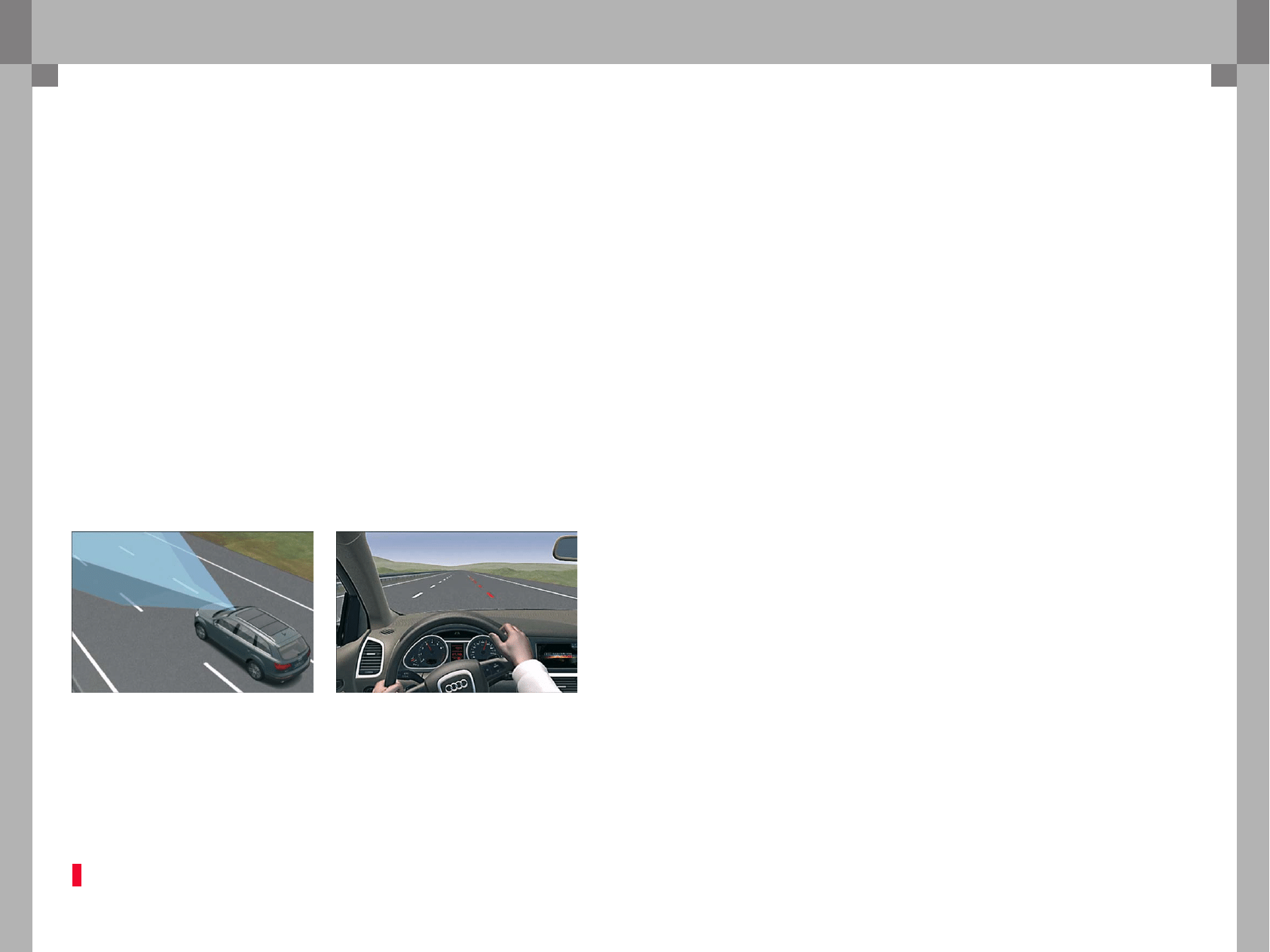
Function
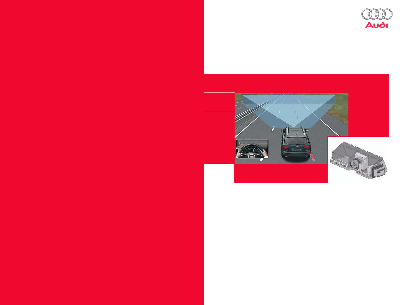
Audi lane assist helps the driver to stay in lane.
A camera is used for detecting lane markers.
Audi lane assist is "on alert" when lane markers are
detected on either side of the lane in which the
vehicle is driving. When the vehicle approaches
a detected lane marker and is about to leave the
lane in which it is driving, Audi lane assist alerts the
driver by making the steering wheel vibrate. If Audi
lane assist is "on alert" and the driver indicates
before crossing a lane marker, no warning is given
because the system assumes that the lane change is
deliberate.
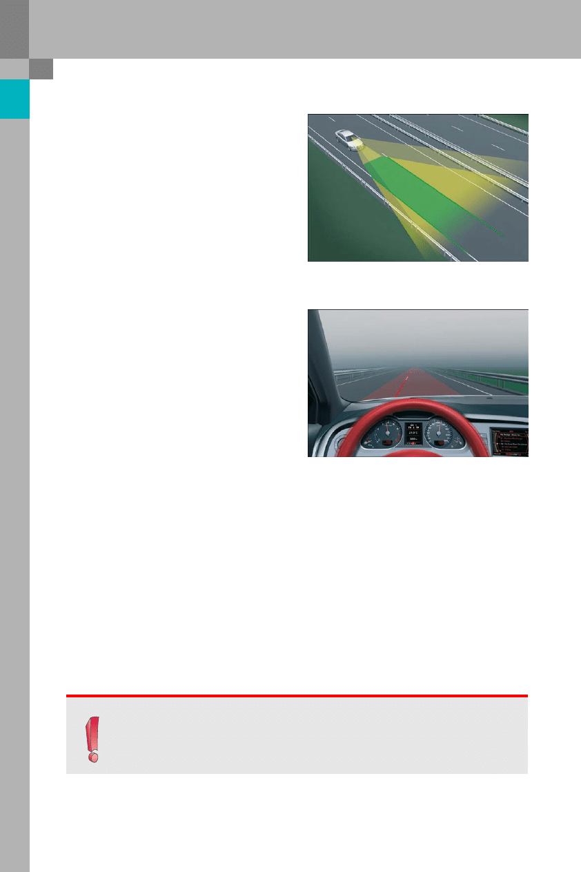
The steering wheel vibrates once only in order to
alert the driver when the vehicle is approaching or
crossing a detected lane marker. A second warning
is only given if the vehicle has moved a sufficient
distance away from the lane marker after the first
warning and subsequently approaches the lane
marker again. This avoids warnings being given
continuously when the vehicle is travelling in
parallel with a lane marker.
The system is designed for use on motorways and
trunk roads. For this reason, it does not become
active until the vehicle is travelling at a speed of
approx. 65 kph or higher.
Adverse ambient conditions, e.g. dirty or snow-
covered road surface, a lane being too narrow or
ambiguous lane markers such as occur in road
works on motorways, may result in the system
being temporarily unavailable. Current system
status is indicated to the driver on the dash panel
insert.
Function
Note
Audi lane assist is a driver assistance system. The system helps the driver to avoid leaving
a lane inadvertently by issuing an alert warning before the vehicle crosses detected lane
markers. However, the responsibility for staying in lane ultimately rests with the driver!
398_037
398_034
5
Displays
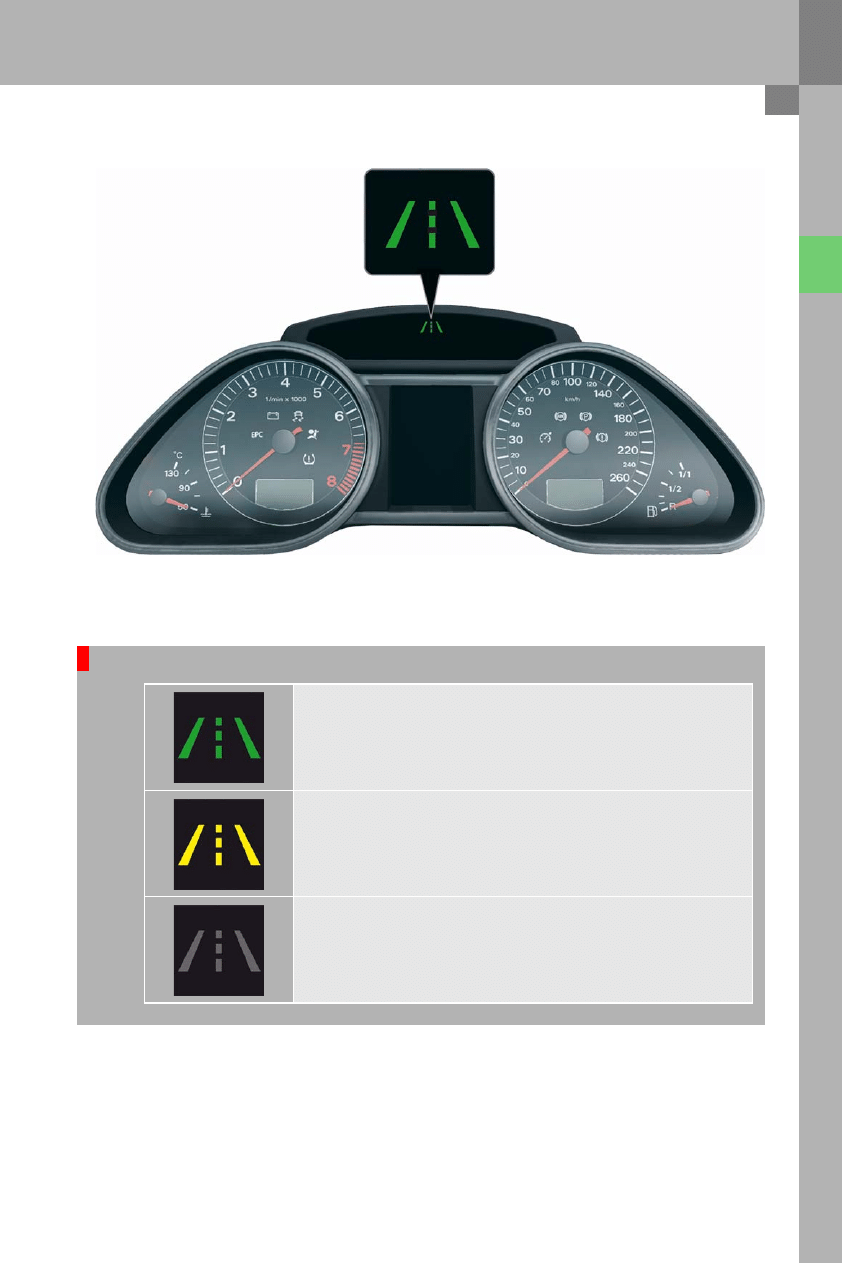
Warning lamp on dash panel insert
Possible states of the warning lamp
If the warning lamp on the dash panel insert is lit green, the system is active and "on alert".
If the warning lamp on the dash panel insert is lit yellow, this means that the system is active
but not "on alert" due to the prevailing conditions.
In this condition, Audi lane assist does not assist the driver and gives no alert warnings.
Possible reasons for deactivation are given below.
If Audi lane assist warning lamp is not lit, then the system is inactive.
To activate the system, push the Audi lane assist button on the indicator stalk.
398_002

6
Displays
If the yellow warning lamp is lit on the dash panel insert, this can be due to the following
reasons:
l
There is only one or no lane marker.
l
The system is not detecting lane markers (e.g. due to snow, dirt, wet, backlight).
l
There are more than two lane markers in the lane in which the vehicle is travelling (e.g. white and yellow
markers at road works).
l
The vehicle is travelling at less than the minimum activation speed of approx. 65 kph.
l
The lane is narrower than approx. 2.5 m or wider than approx. 5 m.
l
The curve is too tight (curve radius less than approx. 250 m).
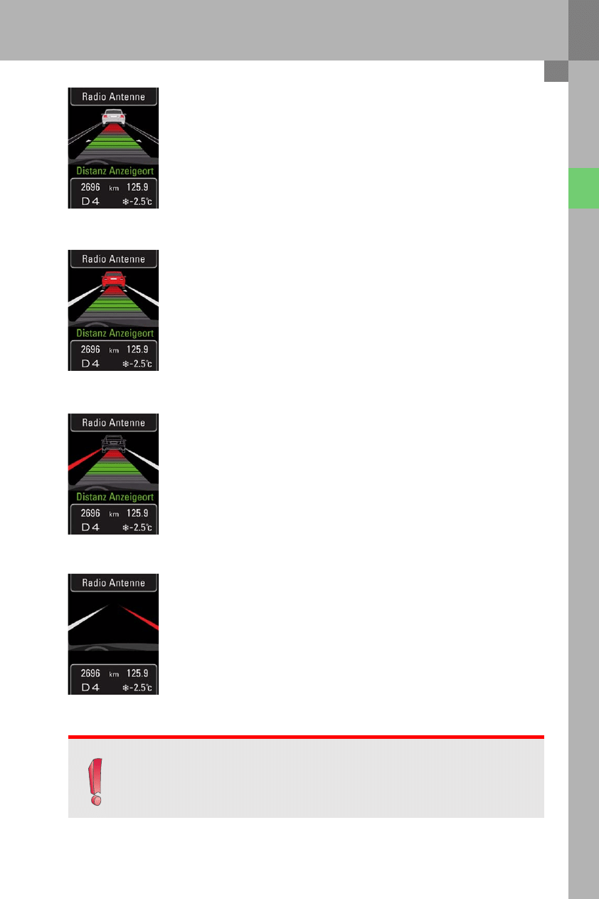
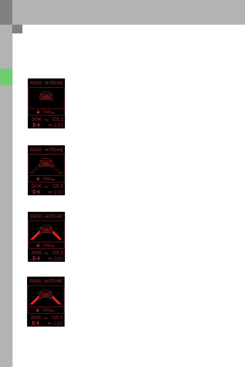
Additional function display in the Audi A4 and A5 Coupé
An Audi A4 and A5 Coupé with Highline dash panel insert offers an additional function display which indicates
the current status of the adaptive cruise control (ACC) and Audi lane assist systems.
The following examples show the combined colour display:
The graphic display indicates the following:
– adaptive cruise control:
active, the system has detected a vehicle
– Audi lane assist:
not installed or switched off
398_024
The graphic display indicates the following:
– adaptive cruise control:
off or in Standby mode
– Audi lane assist:
not installed or switched off
398_025
7
The graphic display indicates the following:
– adaptive cruise control:
active, the system has detected a vehicle
– Audi lane assist:
switched on, but inactive (not "on alert")
The graphic display indicates the following:
– adaptive cruise control:
active, driver is requested to take control
– Audi lane assist:
switched on and active ("on alert")
The graphic display indicates the following:
– adaptive cruise control:
active, the system is not detecting a vehicle
– Audi lane assist:
switched on, active ("on alert") and alert warning on left-hand side
The graphic display indicates the following:
– adaptive cruise control:
no ACC installed!
– Audi lane assist:
switched on, active ("on alert") and alert warning on right-hand side
398_026
398_027
398_028
398_029
Note
If an Audi A4 and A5 Coupé with Highline dash panel insert only has either of the two optional
extras, only the graphic relevant to the function is shown on the colour display.
8
Displays
adaptive cruise control is not available as optional equipment for the Audi A4 and A5 Coupé with Lowline dash
panel insert. The Highline dash panel insert is a mandatory in combination with ACC. If the vehicle is equipped
with Audi lane assist, however, the additional function displays are as follows:
The graphic display indicates the following:
– adaptive cruise control:
no ACC installed!
– Audi lane assist:
switched off
The graphic display indicates the following:
– adaptive cruise control:
no ACC installed!
– Audi lane assist:
switched on, but inactive (not "on alert")
The graphic display indicates the following:
– adaptive cruise control:
no ACC installed!
– Audi lane assist:
switched on and active ("on alert")
(Neither of the two lane markers is flashing!
No warning is given.)
The graphic display indicates the following:
– adaptive cruise control:
no ACC installed!
– Audi lane assist:
switched on and active ("on alert").
The right lane marker is flashing. This means that Audi lane assist is
alerting the driver to the fact that the vehicle has crossed the right
lane marker!
398_030
398_031
398_032
398_033
9
The message "Audi lane assist unavailable: sensor
currently has no visibility" may be displayed for the
following reasons:
1
The exterior of the camera viewing window is
dirty or iced-up. In this event, the driver should
de-ice or clean the viewing window as required.
2
The camera viewing window is misted on the
inside.
In this case, it is recommended to wait until the
system has been de-misted.
3
No lane markings are detectable due to the
prevailing road conditions
(e.g. snow-covered or dirty).
Text messages on the dash panel insert centre display
The message "Audi lane assist currently
unavailable" is displayed when a temporary fault
occurs.
An attempt should be made to activate the system
a short time later.
The can, for example, be due to excess temperature
inside the control unit.
The message "Audi lane assist unavailable: system
fault" is displayed in the event of a fault of such
severity that it is necessary to take the vehicle to an
Audi Service Partner.
Audi lane assist should be checked by an authorised
service station at the next opportunity.
Possible reasons for this are a faulty control unit,
a faulty vibration motor or a faulty Audi lane assist
button.
The same display appears when status "System not
calibrated" is indicated on the control unit.
398_004
398_004
398_004
Audi lane assist
unavailable:
No sensor view
right now
Audi lane assist
currently
unavailable
Audi lane assist
unavailable:
System fault
10
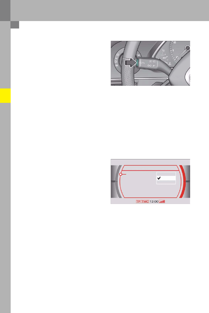
The Audi lane assist button E517 is integrated in the
indicator stalk. Pushing the button switches the
system on or off.
Current system status is indicated by the warning
lamp on the dash panel insert. The system is "on"
when the warning lamp is lit and "off" when the
lamp is not lit.
Actual activation status is stored and assigned to
the corresponding ignition key.
This means: if Audi lane assist was active the last
time the ignition was turned on, the system is
reactivated the next time the ignition is turned on.
A prerequisite is use of the same ignition key as
during the previous trip.
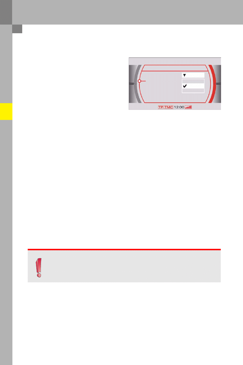
Setting the warning point
The driver can decide whether an alert warning is to
be given before the vehicle inadvertently leaves the
lane, or not until a wheel makes contact with the
lane marker. There are three possible warning point
settings on the MMI. The relevant submenu can be
accessed as follows:
–
press the function key "Car" on the MMI control
panel
–
select the subitem "Systems"
–
select the "Audi lane assist" system
–
open the options menu of subitem "Warning
point"
–
set the warning point to "advance", "adaptive" or
"late"
Operation
Switching the system on and off
398_022
398_005
Vehicle wallet
Audi lane assist
Car
Warning point
Steering wheel
vibration
advance
adaptive
Late
Version

11
Notes on warning point setting options
advance
In this setting, the driver is warned before a wheel makes contact with the detected lane marker.
The warning point is dependent on angle of approach to the lane marker. If the vehicle approaches the lane
marker at an obtuse angle, the warning is given at a greater distance from the lane marker. If the vehicle
approaches the lane marker at an acute angle, the warning is given when the wheel makes contact with the
line.
adaptive
In this setting, the warning point is adapted to the course of the road and the speed at which the vehicle is
travelling. Alert warnings are given later in curves and earlier on straights. Alert warnings are given later
on narrow roads than on wide roads.
late
In this setting, a warning is given before a wheel makes contact with the detected lane marker.
12
Setting the steering wheel vibration
The driver can choose between three different
settings for steering wheel vibration level on the
MMI. The corresponding submenu is accessed as
follows:
–
press the function key "Car" on the MMI control
panel
–
select the subitem "Systems"
–
select the "Audi lane assist" system
–
open the options menu of subitem "Steering
wheel vibration"
–
set the steering wheel vibration level to "low",
"medium" or "high" as required
After setting the steering wheel vibration level,
the steering wheel vibrates once at the level set.
This allows the driver to check the set vibration level
immediately.
Operation
Note
The Audi lane assist settings on the MMI are stored when the ignition is turned off and
assigned to the corresponding ignition key.
The settings of the ignition key currently in use are re-activated after the ignition is turned on.
398_006
Vehicle wallet
Audi lane assist
Car
Warning point
Steering wheel
vibration
low
medium
high
Version
adaptive
13
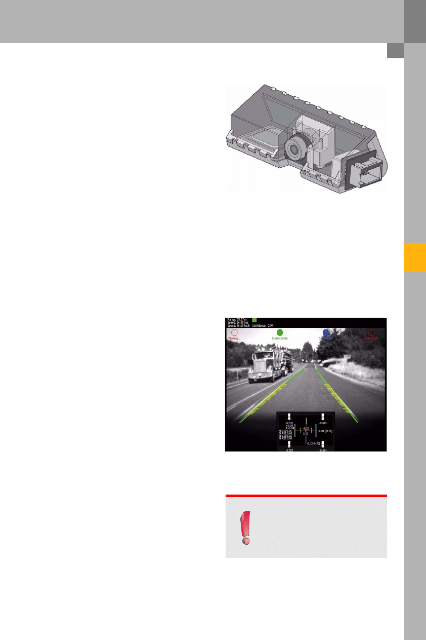
The Audi lane assist control unit and the camera are
an integral unit and can only be replaced as a whole.
Electrical components
398_007
Audi lane assist control unit J759 with camera
Electronic image processing
The black and white image made by the image
acquisition sensor is analysed by image processing
software. Firstly, the system scans the image for
lane markers. If the system detects lane markers on
both sides of the vehicle, it calculates the width and
curvature of the lane.
In addition to this, the software calculates the
position of the vehicle in the lane, i.e. the distance
from the vehicle to the left or right lane marker and
the angle of approach to the lane marker. The image
processing software also assesses the quality of
road recognition.
The warning point is determined from the
calculated values and the known measurements of
the vehicle. Different methods of calculation are
used depending on what warning point is set on the
MMI. They are also required to establish whether or
not to deactivate the function temporarily due to the
road geometry.
398_008
Note
Image 398_008 has been acquired
using special software designed by
Audi's technical development centre.
It cannot be shown on the MMI
display.
The image acquisition sensor scans the road ahead of the vehicle in the form of a black and white image.
It has a resolution of 640 x 480 pixels. The image acquisition sensor has a lens with a focal length of 6 mm.
The camera has an optical range of up to 60 metres. Environmental influences may reduce the camera's
optical range. If the optical range falls below the minimum level, the system switches over to "not on alert""
status.
14
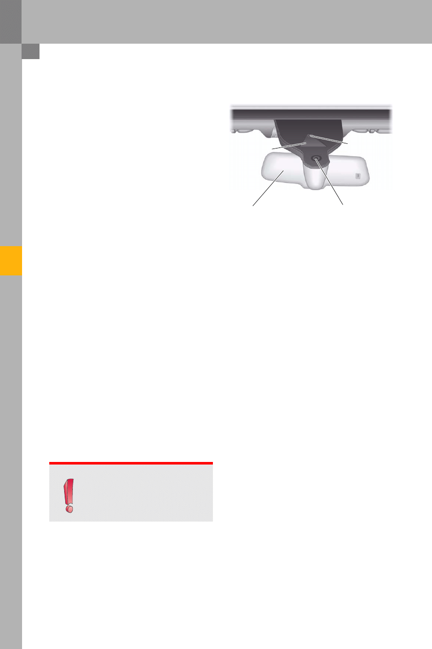
Installation location
The Audi lane assist control unit J759 is clipped into
a holder. The holder is glued onto the windscreen
and supplied together with the windscreen as an
assembly part. Audi is currently working on
a service solution which will allow the holder to be
replaced separately.
The holder is not visible from the exterior, as it is
located behind the black print on the windscreen.
Only the trapezoidal camera viewing window of the
Audi lane assist system is visible. The camera
viewing window is positioned within the wiping
field of the windscreen wiper in order to minimise
visibility impairment due to rainfall and snowfall.
Electrical components
398_009
Note
For logistical reasons, vehicles with
Audi lane assist are always equipped
with a rain-light sensor.
Camera lens
Rain-light sensor
Trapezoidal camera
viewing window
Rearview mirror

15
Audi lane assist has a heated camera viewing
window which de-mists and de-ices the camera
viewing window in combination with the
windscreen wiper.
The Audi lane assist windscreen heater Z67 is
designed as an etched foil resistance heating
element. It is glued directly onto the windscreen.
It has two terminals: one of the terminals is
supplied with battery voltage via the Audi lane
assist control unit J759 while the windscreen heater
is active; the other terminal connects the heater
to vehicle ground.
A multiplicity of parallel resistors on the etched foil
resistance heating element generate heat by
allowing electrical current to flow through them.
The heated resistors heat the windscreen. This
eliminates misting and thaws ice to the extent that
it can be removed by the windscreen wiper.
The etched foil resistance heating element
surrounds the windscreen section through which
the Audi lane assist camera scans the road ahead of
the vehicle.
The windscreen heater Z67 is activated if the image
generated by image sensor does not have enough
contrast. If the image does not have enough
contrast, the lane markers cannot be identified
sufficiently and the function switches over to "not
on alert" status.
When the image again has enough contrast for
purposes of lane detection, the windscreen heater
is reactivated.
If visibility impairment cannot be eliminated by the
heater (e.g. due to dirt), the driver is notified of this
fact by a text message (see Chapter 3) on the centre
display of the dash panel insert.
Audi lane assist windscreen heater Z67
398_011
16
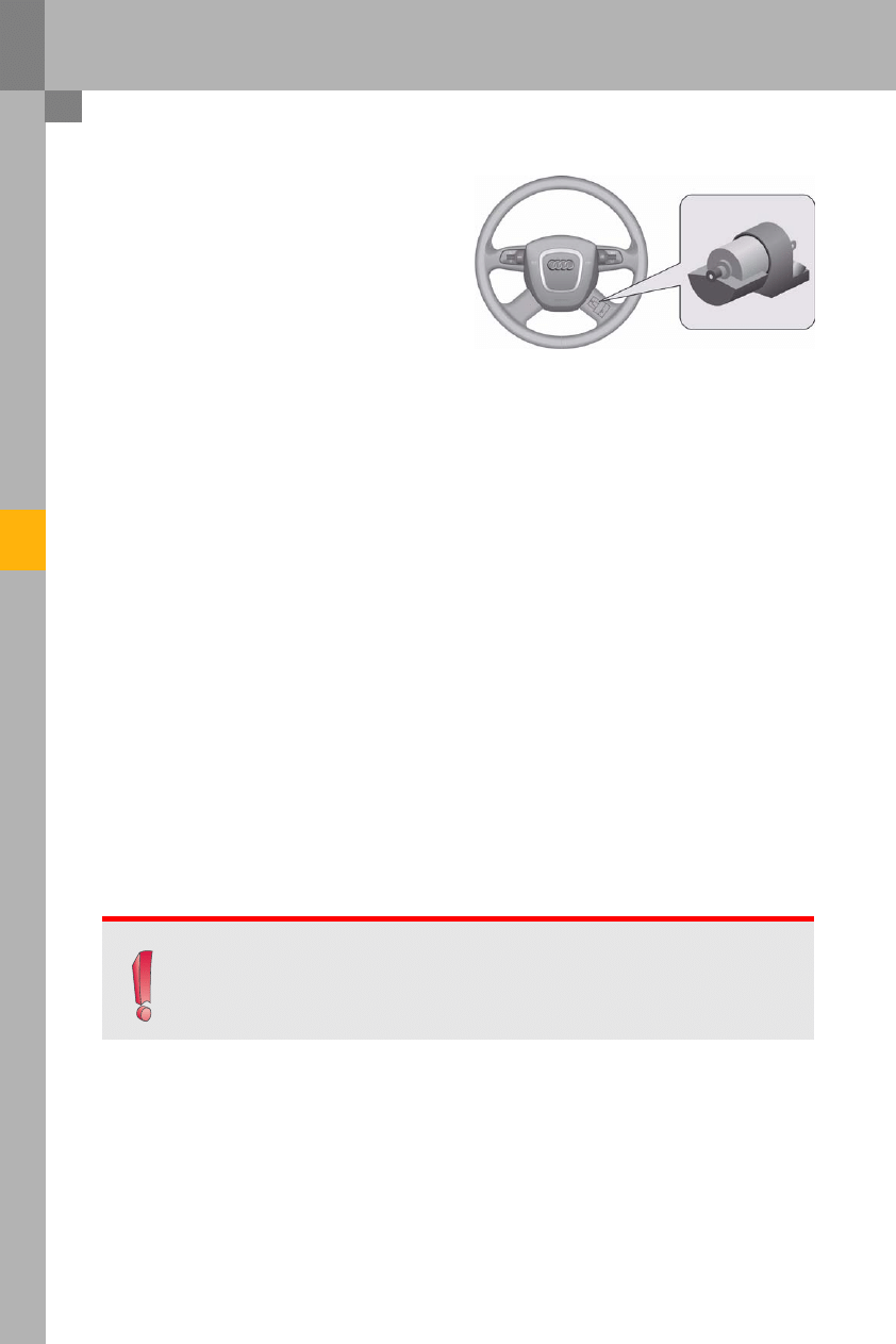
The steering wheel has a vibration motor which
produces vibration of the steering wheel.
The vibration motor is integrated in the bottom right
steering wheel spoke.
Steering wheel vibrations are produced by the
rotation of an imbalance attached to the motor.
The motor cannot be replaced separately. If the
vibration motor is faulty, the whole steering wheel
must be replaced.
The duration of steering wheel vibration is
dependent on the driver's reaction and is usually
about one second.
Electrical components
Vibration steering wheel for Audi lane assist
Note
Vehicles with Audi lane assist require a multifunction steering wheel. The reason for this is that
the vibration motor is activated by the multifunction steering wheel electronics.
The vibration motor is always integrated in a 4-spoke steering wheel.
398_013
17
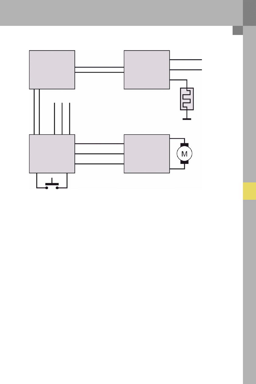
System overview
System overview
Audi lane assist windscreen heater Z67
The Audi lane assist windscreen heater Z67 is activated directly by the Audi lane assist control unit. Only one
terminal is required for this purpose. The windscreen heater is assigned to a ground terminal on the vehicle.
Audi lane assist button E517
The Audi lane assist button E517 is read in by the steering column electronics control unit J527.
It is integrated in the indicator stalk.
Audi lane assist vibration motor
The Audi lane assist vibration motor is activated by the multifunction steering wheel J453. It is integrated in
a steering wheel spoke.
398_014
Data bus diagnostic
interface
J533
Audi lane assist
control unit
J759
Steering column
electronics
control unit
J527
Multi-function steering
wheel control unit
J453
Extended-CAN High
Extended-CAN Low
Terminal 15
Terminal 31
Audi lane assist
windscreen heater
Z67
Audi lane assist
vibration motor
Audi lane assist
button
E517
Terminal 30g
Terminal 31
LIN bus
C
o
nv
en
ie
nc
e
C
A
N
bus
H
igh
C
o
nv
en
ie
nc
e
C
A
N
bus
Lo
w
Te
rm
in
a
l 1
5
Te
rm
in
a
l 3
0
Te
rm
in
a
l 3
1
18
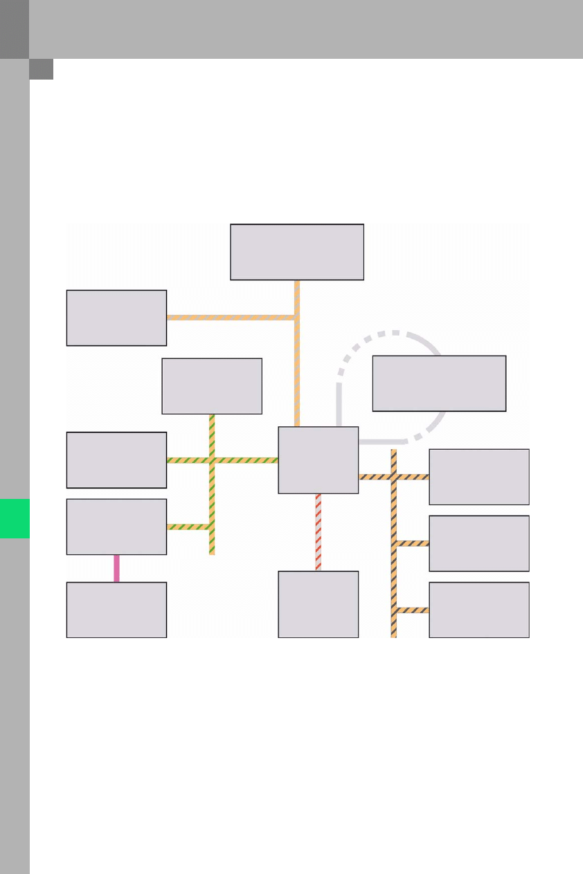
Communication structure
Communication structure
The following diagram summarises all the control units which contribute to the Audi lane assist function.
They transmit information to and receive information from the Audi lane assist control unit J759.
398_015
A description is given below of the control units which exchange information with the Audi lane assist control
unit and the information exchanged. The description is structured according to the bus systems to which the
control unit is connected.
Adaptive cruise
control unit
J428
Convenience system
central control unit
J393
Steering column electronics
control unit
J527
Multi-function steering
wheel control unit
J453
Engine control unit
J623
ABS control unit
J104
Adaptive suspension
control unit
J197
Entry and start
authorisation control unit
J518
Audi lane assist
control unit
J759
Front information
control unit
J523
Data bus diagnostic
interface
J533
Control unit with
display in dash panel
insert
J285
Extended-CAN
Most bus
C
o
nveni
e
nce CA
N bus
Da
s
h
p
a
n
e
l i
n
s
e
rt
CAN
bus
Po
w
e
rt
ra
in
C
A
N
b
u
s

19
Extended-CAN users
1
Adaptive cruise control unit J428
To avoid warnings being given simultaneously by Audi lane assist and Stopping Distance Reduction system 2,
Audi lane assist suppresses its steering-wheel vibration warning if the Stopping Distance Reduction system
simultaneously activates the brake.
Convenience CAN bus users
2
Entry and start authorisation control unit J518
transmits information on which ignition key is currently recognised by the vehicle. The Audi lane assist control
unit utilises this information to assign stored driver settings to the corresponding ignition key.
3
Convenience system central control unit J393
transmits information on whether the left or right indicator is currently active.
4
Steering column electronics control unit J527
transmits information on whether the Audi lane assist button on the steering column stalk is being actuated
or not.
receives from Audi lane assist the information on whether or not to activate the driver-alert vibration motor.
This information is then sent via a LIN bus message to the multifunction steering wheel, which activates the
vibration motor.
MOST-bus users
5Front information control unit J523
transmits changes in driver settings relevant to the "Audi lane assist" function to the Audi lane assist control
unit. The new settings are then saved and assigned to the ignition key currently in use.

20
Communication structure
Powertrain CAN bus users
6
Engine control unit J623
transmits the current engine speed. Audi lane assist requires this data, because the activation times of the
windscreen heater are dependent on whether the engine is presently running or not.
(no heating phases are allowed at "engine off".)
7
Adaptive suspension control unit J197
keeps Audi lane assist informed at all times about the actual height of the dampers on the vehicle.
This data is required for electronic correction of the current camera height, as well as the pitch and roll angle
of the camera.
8
ABS control unit J104
supplies the vehicle speed signal required for activating or deactivating Audi lane assist, as well as the yaw
velocity.
Convenience CAN bus users
9
Control unit with display in dash panel insert J285
receives information on the current status of Audi lane assist for activating the warning lamp on the dash
panel insert (yellow, green or off).
receives information on whether or not to display a text message and, if so, what text message.
21
System calibration
Task of calibration
The calibration procedure involves determining the actual orientation angle of the camera on the vehicle.
To make an exact determination, the installed position of the camera on the vehicle must be known.
Deviations from the nominal installed position can occur due to component tolerances of the holder or
windscreen or because of manufacturing tolerances.
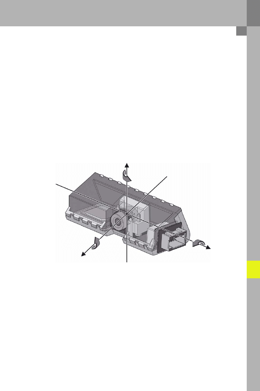
The system must be calibrated in order to compensate for these effects. The calibration procedure involves
determining the three orientation angles of the camera in relation to the vehicle's direction of travel, as well as
the height at which the camera is installed in relation to the tyre contact area. The calibration is made
electronically. There are no mechanical adjustments on the camera.
The three orientation angles are as follows:
–
Roll angle
(rotation about the x-axis)
–
Pitch angle (rotation about the y-axis)
–
Yaw angle (rotation about the z-axis)
Calibration principle
The orientation angles of the Audi lane assist camera cannot be determined directly. They are calculated using
a calibration board. The calibration board consists of geometric elements which contrast distinctly with the
rest of the board.
The board is aligned in a reference position in front of the vehicle. The camera then records images of the
calibration board. The position of the geometric elements on the image is determined. A software routine
uses the image co-ordinates and the known reference position of the board to determine the camera's actual
orientation angle, and stores this information in the control unit. The actual height of the camera on the
vehicle is also determined.
z-axis
x-axis
y-axis
Yaw angle
Roll angle
Pitch angle
398_016
22
New special tools are required for calibrating Audi
lane assist. They belong to tool family VAS 6430.
This device can be used for calibrating both Audi
lane assist and Active Cruise Control ACC.
Special tool VAS 6430 is a complete set and includes
the following separately available components:
l
VAS 6430/1 calibration device basic set
l
VAS 6430/2 ACC laser unit (VW)
l
VAS 6430/3 ACC reflector mirror (Audi)
l
VAS 6430/4 Audi lane assist calibration board
The VAS 6430 complete set is intended for service
partners who are still not equipped with an ACC
calibration device.
Customers who already have an ACC calibration
device VAS 6190 needs only order the components
VAS 6430/1 and VAS 6430/4 in order to have
a complete calibration device suitable for both
systems. The existing ACC laser unit by VW and the
ACC reflector mirror by Audi can be attached to the
new calibration device VAS 6430/1.
System calibration
New special calibration tools
398_018
Note
The calibration board for Audi lane
assist VAS 6430/4 does not attach to
the ACC calibration device VAS 6190.
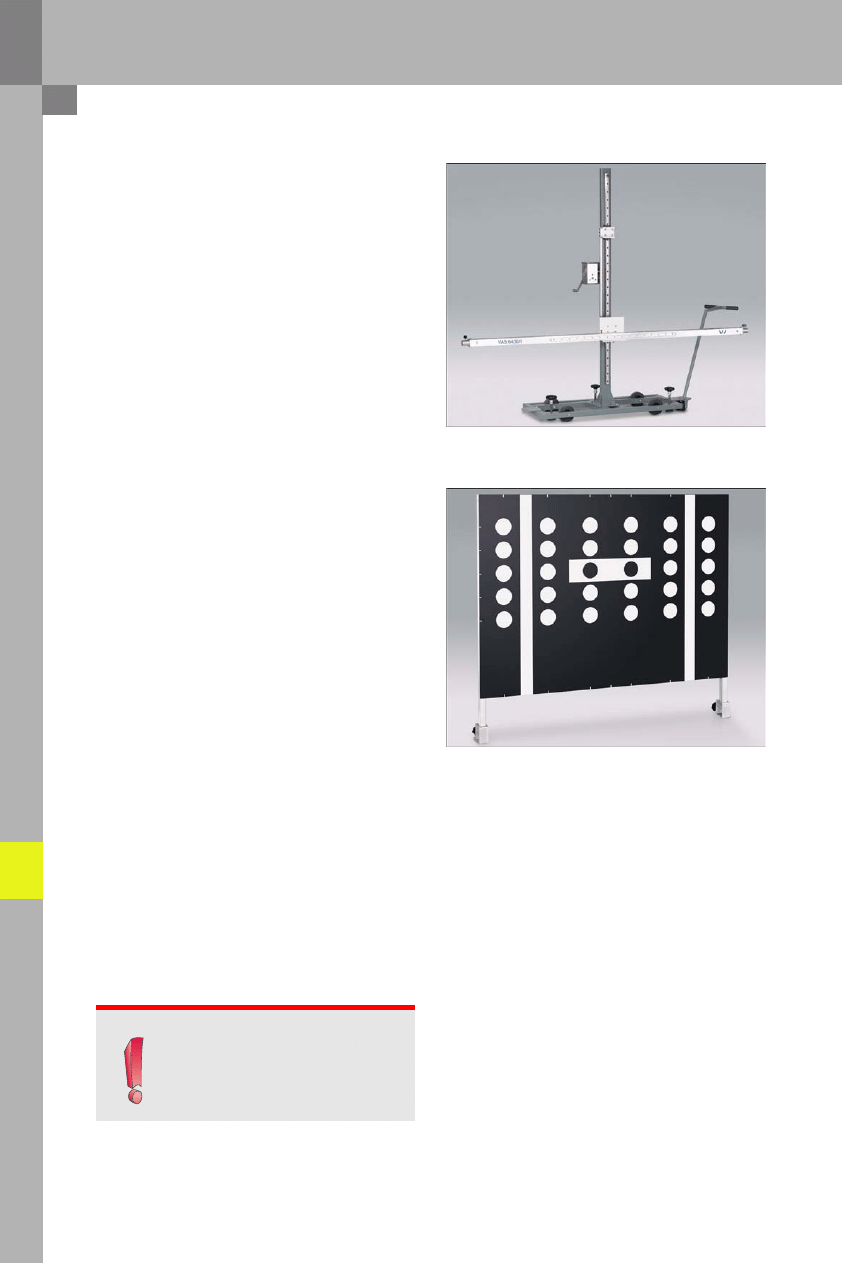
398_017
VAS 6430/1 calibration device (basic set)
VAS 6430/4 Audi lane assist calibration board

23
The following tools are required to calibrate the
Audi lane assist system:
l
Diagnostic tester (VAS 5051B or VAS 5052)
l
Approved wheel alignment computer including
wheel alignment lift
l
Calibration tools VAS 6430/1 and VAS 6430/4
Tools requires for the calibration
398_020
When is it necessary to calibrate the system?
The Audi lane assist system has to be calibrated for the following reasons:
–
The fault memory contains the entry "no or incorrect basic settings/adaption".
–
The Audi lane assist control unit has been replaced.
–
The windscreen has been replaced or removed.
–
Rear axle toe has been adjusted.
–
Modifications affecting body height have been made to the vehicle's suspension system.
–
The level senders on vehicles with damping control or air suspension have been readapted.

24
System calibration
Calibration procedure
For details of the exact calibration procedure, refer to in the Workshop Manual.
The main calibration steps are described below:
–
The "Calibration Audi lane assist" program is started on the wheel alignment computer.
–
Quick release clamps are mounted on all 4 wheels.
–
Transducers are mounted on the rear two wheels.
–
Wheel runout compensation is performed on the rear wheels.
–
Two transducers are attached to the VAS 6430.
–
The calibration device VAS 6430 is aligned with the direction of travel in several steps using the wheel
alignment computer as a guide.
–
The calibration program on the diagnostic tester is started under "Guided Fault Finding".
–
Body height is measured at the front left and right wheel arch edges as well as at the rear left and right
wheel arch edges and entered into the program.
–
The calibration routine then runs to completion automatically.
Online calibration
The system also has an "Online calibration" function. In Online calibration mode, the Audi lane assist system
checks while the vehicle is being driven whether the yaw and pitch angle have changed during the calibration.
Any changes are incorporated into the values
l
yaw angle offset and
l
pitch angle offset
and taken into account by the system. The values are represented in a data block.
The two values are reset to zero during the next calibration.

25
Diagnostics
Diagnostics
The Audi lane assist control unit has full self-diagnostic capability. Data blocks, adaption channels, actuator
diagnoses, control unit codings, basic settings and fault memory entries are available. The Audi lane assist
control unit is addressed by the diagnostic tester with address word 5C.
Data blocks on the function
The following values can be read out under the menu item "Data blocks":
l
Control unit supply voltage
l
Measured temperature in control unit
l
Windscreen heater status
l
Reason for activation or deactivation of the windscreen heater
l
Geometric lane data determined by the image processor, e.g.
– Lane width
– Current curve radius
l
Audi lane assist system status (off/on & active/on & inactive)
l
Audi lane assist warning status (warning inactive/active; if active due to left/right hand side warning)
l
Audi lane assist button status (pressed/not pressed)
l
Left direction indicator function (active/inactive)/right direction indicator function (active/inactive)
l
Actual height values generated by the 4 vehicle level senders (if air suspension is installed on the vehicle)
l
Set warning point and warning vibration level
l
Saved personalised settings assigned to the individual remote control keys (system status, warning point
and vibration level)
l
Vibration motor: fault detected (yes/no); Audi lane assist button:fault detected (yes/no);
the information is supplied by the steering column electronics control unit J527
l
Status of communication CAN with control units which transmit the information which Audi lane assist
requires for proper operation
Calibration data blocks
l
Roll, pitch and yaw angles of the camera
l
Camera height
l
Reason for failed calibration
l
Yaw and pitch angle offset
l
Information on the online calibration

26
Diagnosis
Adaption channels
It is possible to reset the complete system to its as-delivered condition via the adaption channels.
The following values can be found on the adaption channels:
l
body height to be measured at the edges of the wheel arch during the calibration:
– front left
– front right
– rear left
– rear right
Since the body height at the wheel arch edges is input into the diagnostic tester calibration program, these
adaption channels are not required in practice.
Actuator diagnoses
The following components can be activated via an actuator diagnosis:
l
Windscreen heater Z67 can be activated by actuator diagnosis on the Audi lane assist control unit J759.
It remains active for approx. 20 seconds.
l
The vibration motor integrated in the steering wheel can be activated by initiating the appropriate actuator
diagnosis on the steering column electronics control unit J527.
l
The Audi lane assist warning lamp on the dash panel insert can be activated via an actuator diagnosis on
the control unit with display in dash panel insert J285 together with the other warning lamps.
Control unit coding
The control unit coding provides the following vehicle information to the Audi lane assist control unit J759:
l
the Audi model in which the system is installed
l
the market for which the vehicle is intended: USA, Japan, United Kingdom or Rest of World
l
whether the vehicle has air suspension or damping control
l
whether the vehicle has the "stopping distance reduction" function
Basic settings
The system calibration is implemented via "Basic settings". However, since the diagnostic tester operator is
guided step by step through the program during the calibration routine, the individual basic settings do not
have to be started individually. The basic settings are initiated automatically by the tester at the correct point
in the program and therefore are executed entirely in the background.
Preface
To mark the launch of the new Q7 premium SUV, Audi extended its range of driver assist systems to include
two new systems: the radar-assisted "Audi side assist" system and the rear-view camera. Both systems met
with a very encouraging response from customers and experts alike. They once again emphasise the fact that
Audi takes its slogan "Vorsprung durch Technik" very seriously.
A logical consequence of this is that Audi is now extending this range to include a new system:
Audi lane assist. This system helps the driver to stay in lane.
In the event that the driver is inattentive or distracted, the vibrating steering wheel can warn when the vehicle
is about to leave its lane. The aim is to help avoid accidents.
Despite the availability of this technology, however, it is still imperative that motorists only get behind the
steering wheel when they feel fit to drive. Audi lane assist is a driver assist system designed to help the driver.
However, the responsibility for staying in lane ultimately rests with the driver.
Under current plans, Audi lane assist will be available on models A4, A5, A6, Q7 and A8.
Excellence in design & performance
ò98_036
ò98_035

398
All rights reserved.
Technical specifications
subject to change without
notice.
Copyright
AUDI AG
I/VK-35
Service.training@audi.de
Fax +49-841/89-36367
AUDI AG
D-85045 Ingolstadt
Technical status: 04/07
Printed in Germany
A07.5S00.38.20
Audi lane assist
Self-Study Programme 398
Vorsprung durch Technik www.audi.de
Service Training
Wyszukiwarka
Podobne podstrony:
Self Study Programme 431 Audi RS 6
Self Study Programme 288 Audi A8 03 distributed functions
Self Study Programme 396 Lane change assist
Self Study Programme 365 4 2L V8 with common rail
Self Study Programme 388 4 2L V8 4V FSI engine
Self Study Programme 17 Octavia convenience electronic system
Self Study Programme 279 2 0L 110kw with petrol direct injection FSI
Self Study Programme 189 2 3L petrol engine in the LT 97
Self Study Programme 376 5 2 litre V10 FSI engine
Self Study Programme 351 Common rail fuel injection system fitted in the 3 0l V6 TDI engine
Self Study Programme 276 Phaeton automatic proximity control
Self Study Programme 280 Phaeton auxiliary heater top c and top z
Extreme Self Care Program
ASM based Modelling of Self Replicating Programs
montaż elektronicznego programatora webasto do Audi A2 TDI
AUDI pilot programowanie
Programowanie klawiszy radia Audi, diagnostyka samochodu, Diagnostyka dokumety, procedury diagnostyc
Atmel Avr Self Programming
więcej podobnych podstron