The Phaeton
Auxiliary heater Thermo TOP C and
supplementary heater Thermo TOP Z
Design and function
Self-study programme 280
Service.
2
NEW Important
Note
This self-study programme explains the design and
function of new developments.
The contents will not be updated.
Please refer to the relevant service literature for
current inspection, adjustment and repair instructions.
The use of heater units that work
independently of the engine is continually rising.
They are offered as an accessory for retrofit or as
an optional extra by the manufacturer.
The petrol engine Phaeton features an auxiliary
heater as an optional extra that heats the interior
when the engine is not running.
For diesel engines, the Phaeton is fitted as
standard with a supplementary heater that
boosts coolant heating when the engine is
running.
In this way, the operating temperature of the
engine is reached faster and is maintained
throughout operation at an equal level.
This self-study programme provides you with an
overview of the auxiliary heater and the
supplementary heater installed in the Phaeton.
S280_053

3
Contents
Introduction . . . . . . . . . . . . . . . . . . . . . . . . . . . . . . . . . . . . . . 4
Operation . . . . . . . . . . . . . . . . . . . . . . . . . . . . . . . . . . . . . . . 6
Overview . . . . . . . . . . . . . . . . . . . . . . . . . . . . . . . . . . . . . . 10
Construction . . . . . . . . . . . . . . . . . . . . . . . . . . . . . . . . . . . . 12
Coolant circuit . . . . . . . . . . . . . . . . . . . . . . . . . . . . . . . . . . . 26
Function . . . . . . . . . . . . . . . . . . . . . . . . . . . . . . . . . . . . . . . . 30
Operating stages . . . . . . . . . . . . . . . . . . . . . . . . . . . . . . . . 32
Deactivation . . . . . . . . . . . . . . . . . . . . . . . . . . . . . . . . . . . . 36
Network . . . . . . . . . . . . . . . . . . . . . . . . . . . . . . . . . . . . . . . 38
Functional diagram . . . . . . . . . . . . . . . . . . . . . . . . . . . . . . . 42
Service . . . . . . . . . . . . . . . . . . . . . . . . . . . . . . . . . . . . . . . . . 44
Glossary . . . . . . . . . . . . . . . . . . . . . . . . . . . . . . . . . . . . . . . . 46
Explanation of highlighted terms
Test yourself . . . . . . . . . . . . . . . . . . . . . . . . . . . . . . . . . . . . . 48
4
Introduction
The auxiliary heater
The auxiliary heater is a wise choice as an
accessory. The heater and ventilation function
provides a comfortable environment in the
interior, which is available as soon as you climb
into the vehicle.
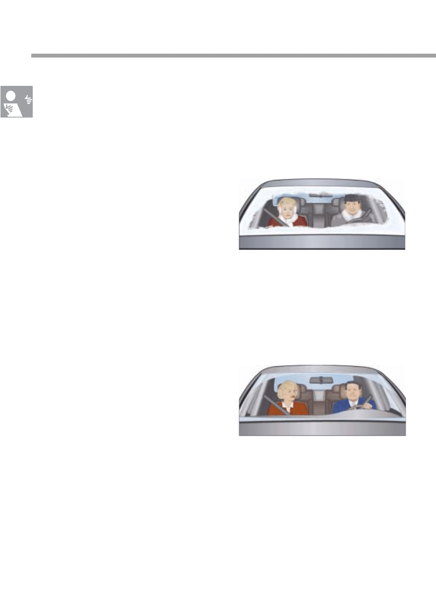
Frosted or steamed up windows inhibit all-round
view. Therefore, they are a considerable risk in
traffic situations.
Heavy winter clothing, when worn in the vehicle,
results in loose seat belts as they are no longer
comfortably taut against the body. The optimal
efficiency of the seat belt is markedly impaired.
A further disadvantage is that unsuitable
clothing restricts freedom and thereby also the
ability to react quickly to given situations.
By heating up the interior before the journey is
started, the windows are cleared.
Good all-round view is guaranteed.
Less restrictive clothing in a preheated vehicle
increases the efficiency of seat belt protection
and reaction time of the wearer.
Further, use of an auxiliary heater is financially
viable. In many regions, the temperature on
100 days of the year is less than +5 °C, which
equals a third of a year of operation.
S280_013
S280_012

5
The supplementary heater
The diesel engines in the Phaeton feature
a heater that works to boost heat.
When the engine is started, the coolant is heated
additionally by the supplementary heater.
This helps diesel engines to make use of their
good efficiency and reach their operating
temperature in a short space of time.
The heat generated from the combustion process
is an unavoidable side-effect. The energy stored
within is converted partly into heat instead of
power.
This has the effect of reducing the degree of
efficiency.
Direct injection diesel engines reach a high level
of efficiency thanks to their optimised combustion
process. The use of a supplementary heater
supports the high level of efficiency in the engine
by heating of the coolant. In addition,
the passenger compartment is heated
comfortably.
6
Activation
Operation
The auxiliary heater can be operated in a number of different ways:
●
Immediate start is carried out via the front information display and operating unit, in the sub-menu of
the air conditioning system.
●
Programming a fixed start time is done via a timer in the same sub-menu.
●
Additionally, the auxiliary heater can be started using a remote control.
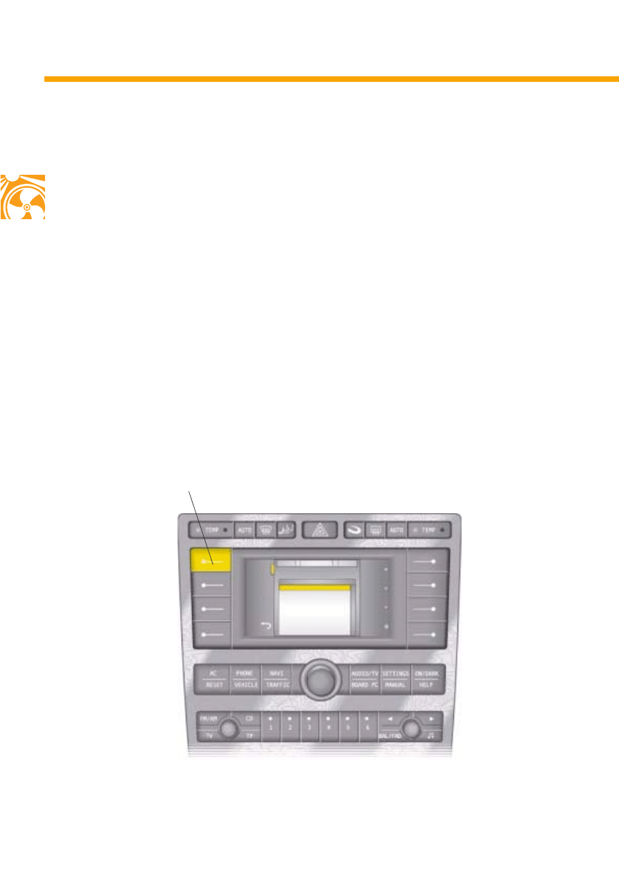
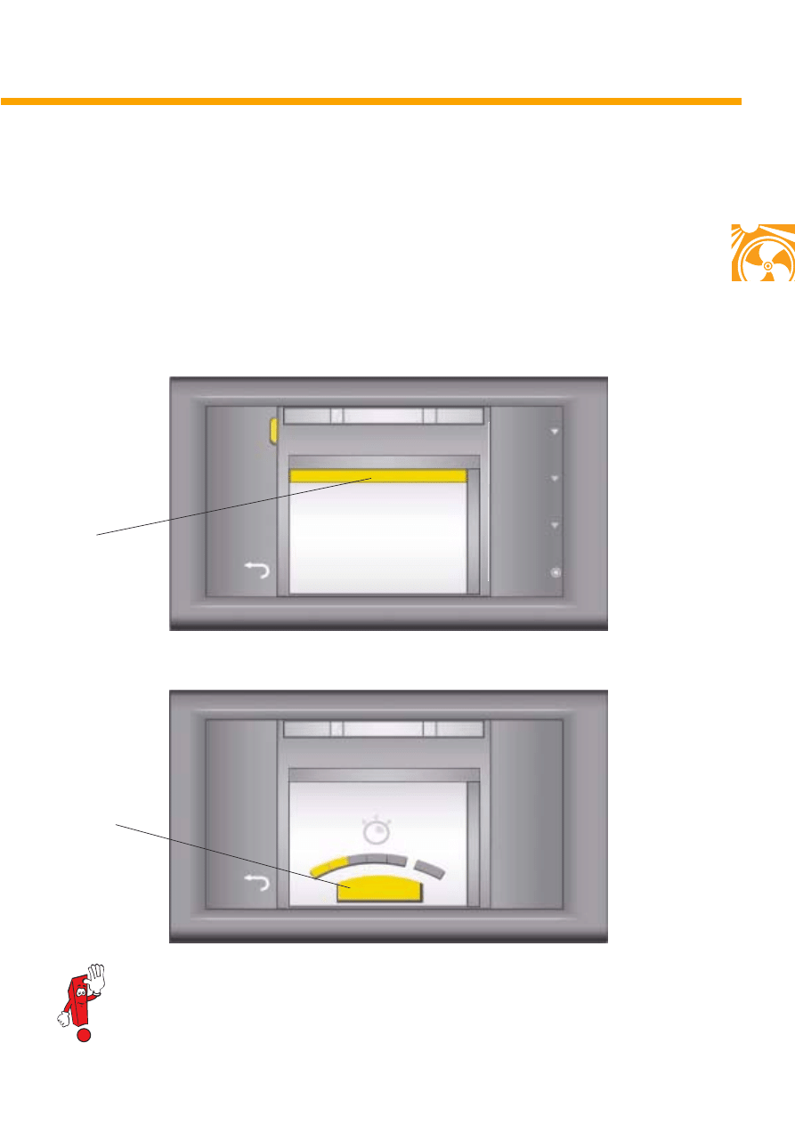
Immediate start
By pressing the auxiliary heater function button, the sub-menu can be accessed
for auxiliary heater control.
The heater button allows manual activation and deactivation of the auxiliary heater.
S280_008
Heater button for immediate start
22°C
22°C
92.8 MHz TP
A/C
Other functions/Auxiliary heater
Timer (duration:10 min)
Monday
06:20
Heater
Back
Duration
Day
Departure
time
Sel-
ection
Front information display and operating unit
7
S280_021
When the auxiliary heater is activated at temperatures above +22 °C, auxiliary ventilation is
activated automatically.
Display: Set duration
Timer preselection
The start time for the heater can be programmed in the sub-menu. To do this, the weekday,
the start time and the desired duration should be entered using the operating elements.
When the weekday and time have been reached, auxiliary heater operation will begin. In addition, the
weekday will jump automatically to the next day.
S280_061
Display:
Weekday,
time
22°C
22°C
92.8 MHz
A/C
Other functions/Auxiliary heater
Timer (duration:10 min)
Monday
06:20
Heater
Back
Duration
Day
Departure
time
Sel-
ection
Display: Timer preselection
TP
Tuesday
08:50
22°C
22°C
92.8 MHz
A/C
..../Auxiliary heater/Heating duration
Back
Confir-
mation
TP
15 min
Display:
Duration
8
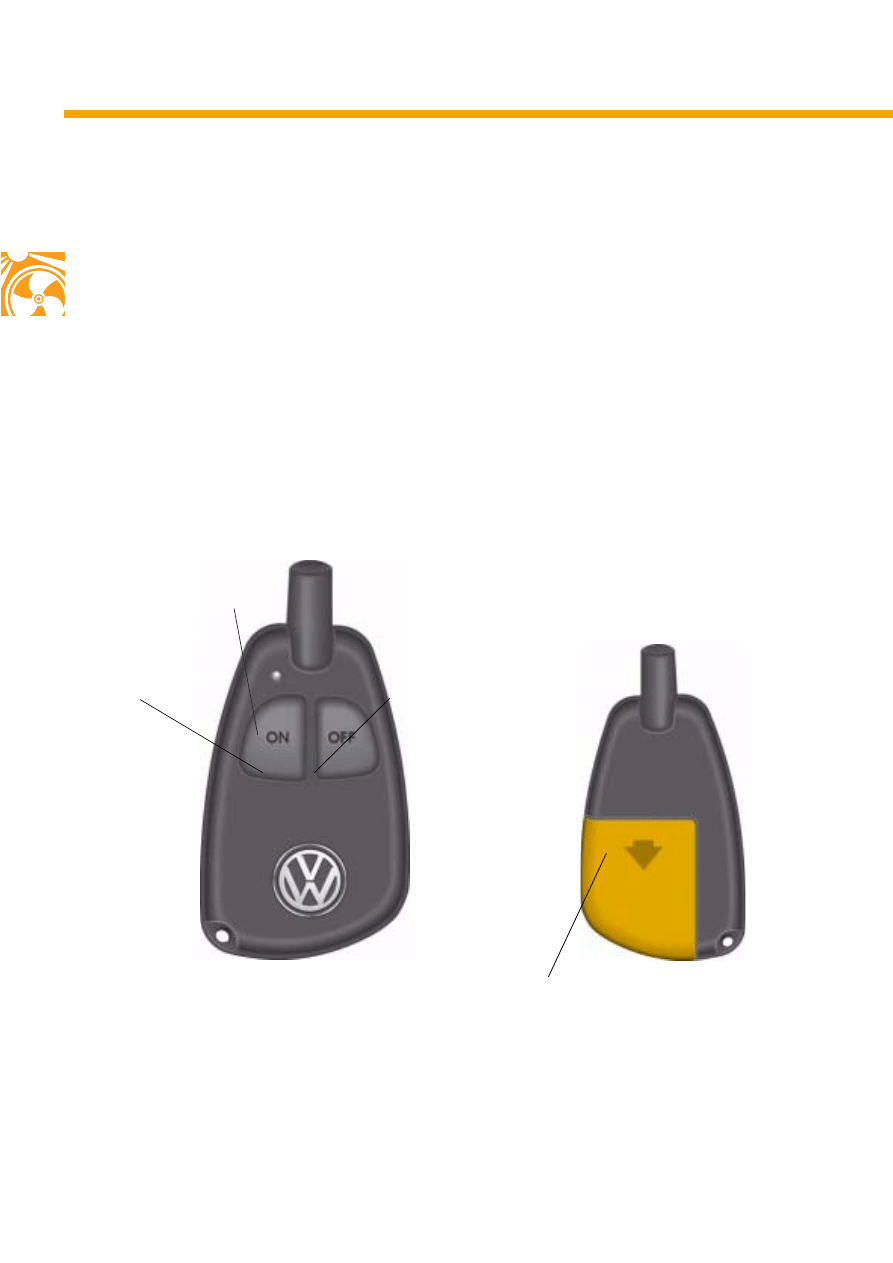
Remote start
The auxiliary heater features an additional
remote control, which is not integrated in the
vehicle key.
With this remote control, the auxiliary heater is
switched on and off remotely.
The on button serves to start the heater and the
off button is used to switch it off.
For power supply of the remote control, a battery
is necessary.
The range of the remote control in open areas is
approx. 600 m.
The control lamp of the remote control lights up
green when the auxiliary heater is switched on,
and red when it is switched off.
Operation
S280_023
On button
Off button
Remote control
Control lamp
S280_066
Opening for battery replacement
9
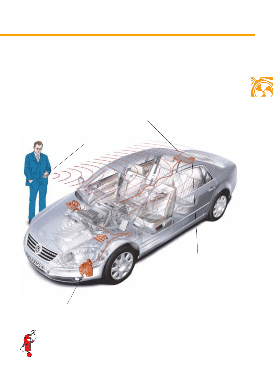
The signal is sent to the auxiliary heater control
unit (J255) by pulse width modulated
transmission along a special data lead.
The radio signal from the remote control is
pikked up by an aerial, which is installed in the
upper area of the rear window, and transmitted
to a receiver located beneath the rear shelf.
The remote control must be coded to the radio receiver. A maximum of two remote controls can
be coded. The work procedure necessary is described in the electronic service information
system (ELSA).
Remote control
Aerial
Radio receiver
Auxiliary heater control unit
S280_019
Overview of associated components
10
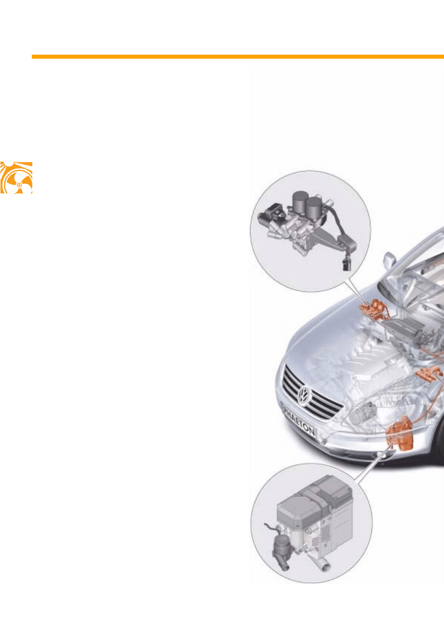
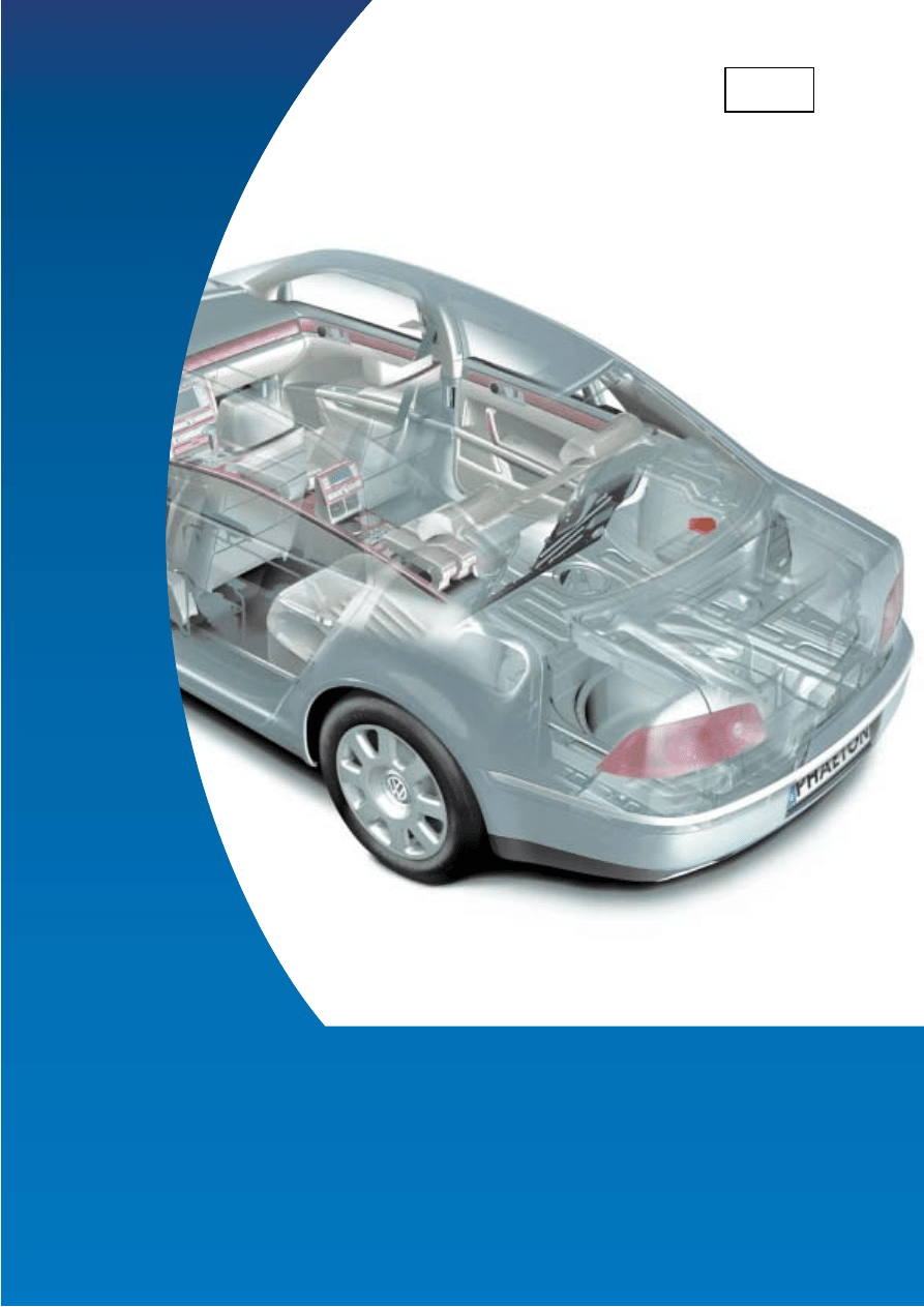
Fitting locations
The components necessary for operation of the
auxiliary heater or the supplementary heater are
installed in the vehicle decentrally.
Overview
Auxiliary/supplementary heater
with control unit,
front left beneath wing
Pump valve unit,
front right in vicinity of plenum
chamber
Overview of fitting locations
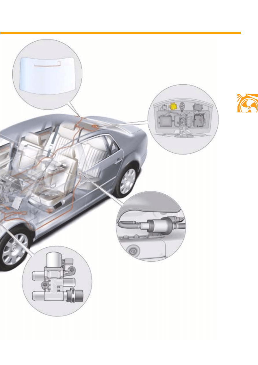
11
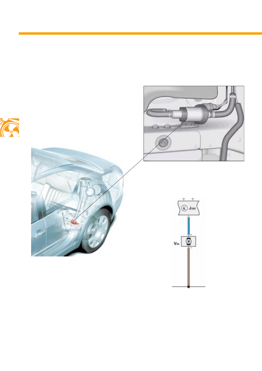
Metering pump,
above rear axle,
left of centre
Radio receiver,
beneath rear shelf
S280_017
Aerial for remote start,
beneath rear window upper
trim
Coolant shutoff valve,
on left in engine compartment
12
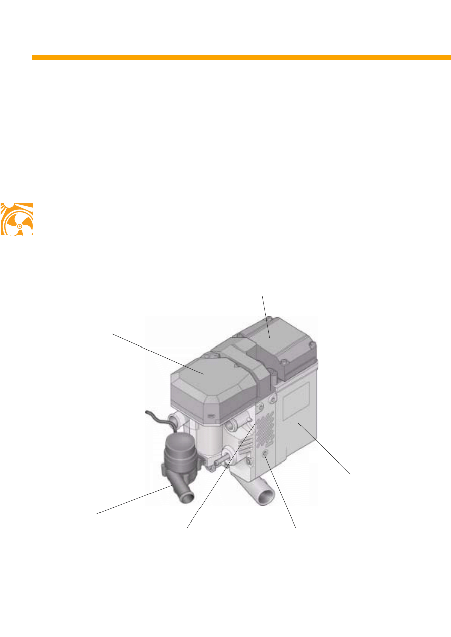
The components
The auxiliary heater and the supplementary
heater consist of:
- recirculating pump V55,
- combustion air blower V6,
- control unit J255,
- burner housing,
- combustion chamber with flame pipe and
glow plug Q9 (with flame monitor) in burner
housing,
- coolant jacket.
Additional components are:
- metering pump V54 and
- coolant shutoff valve N279.
Construction
S280_002
Recirculating pump
Burner housing
Coolant jacket
Combustion air blower V6
Combustion chamber in
burner housing
Thermo Top Z/C (heater)
Control unit
13
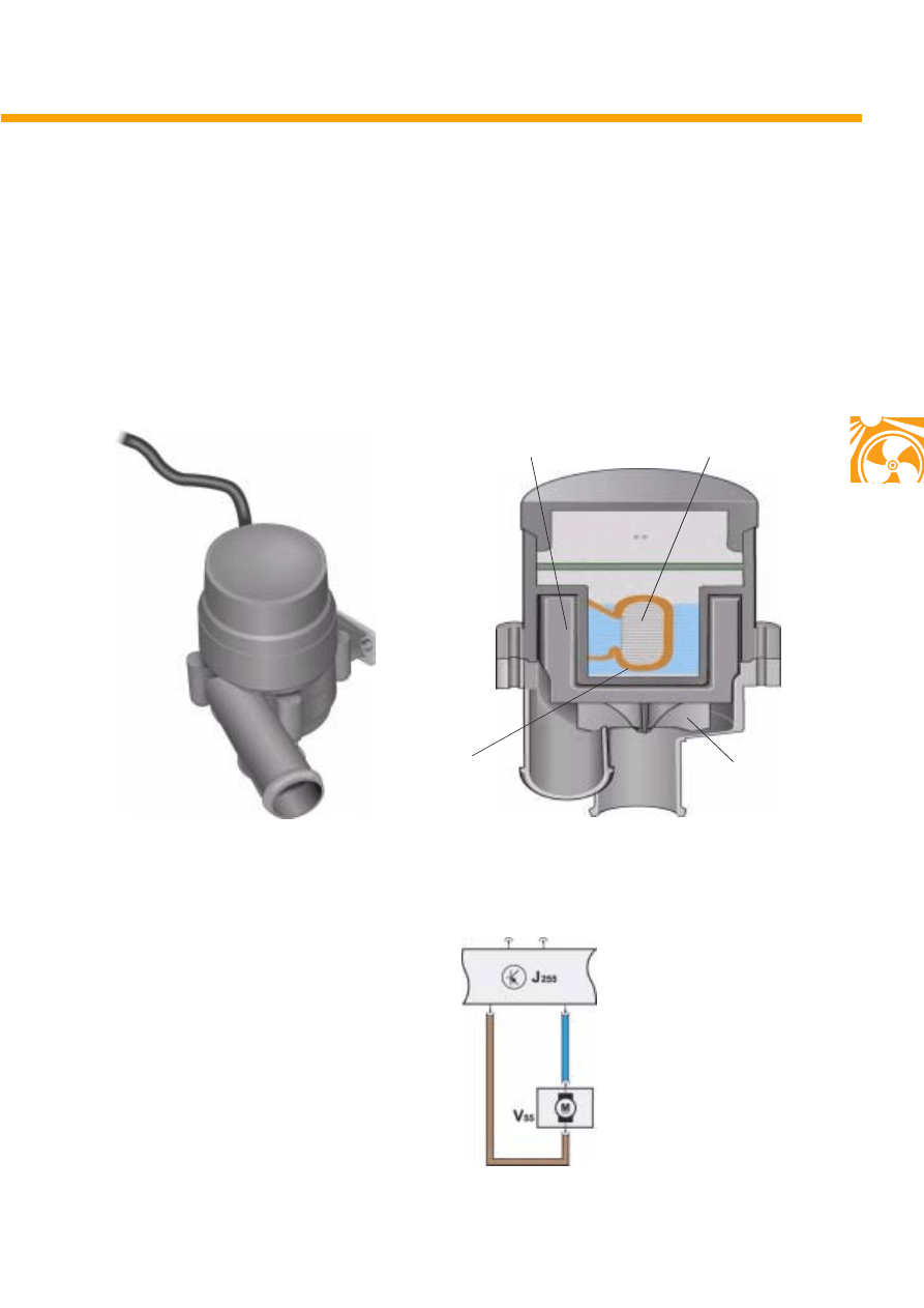
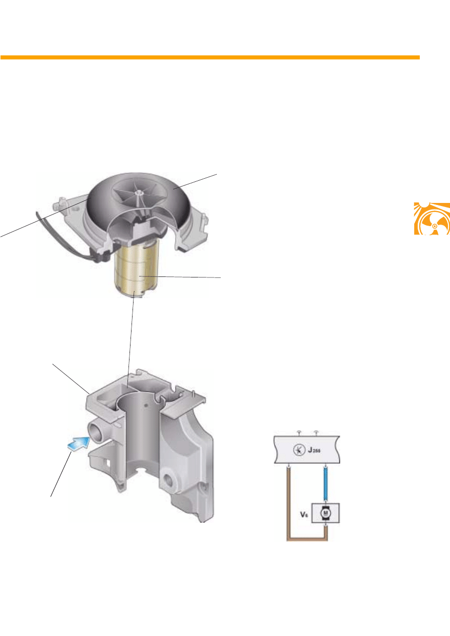
The recirculating pump V55
When the engine is switched off, coolant is
circulated by a recirculating pump. This is
actuated electrically by auxiliary heater control
unit J255.
Actuation
Actuation is by the auxiliary heater control unit.
S280_057
S280_044
S280_007
Recirculating pump
Cross section
Iron core
Permanent magnet
Coil
Pump rotor
14
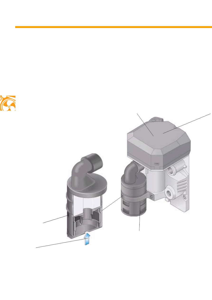
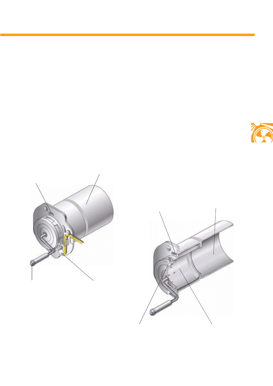
The combustion air blower V6
The air required for combustion is drawn in via
an air intake pipe with silencer by the
combustion air blower, then via the air channel
to the fuel evaporator (fleece) and further to the
combustion chamber.
Construction
S280_003
Silencer
Combustion air blower
Main view
Silencer and filter element
S280_058
Air intake
15
Actuation
The combustion air blower is supplied with
voltage direct from the control unit via a two pin
connector.
S280_047
Blower rotor with vanes
Blower motor
S280_059
S280_055
Housing
Air intake
16
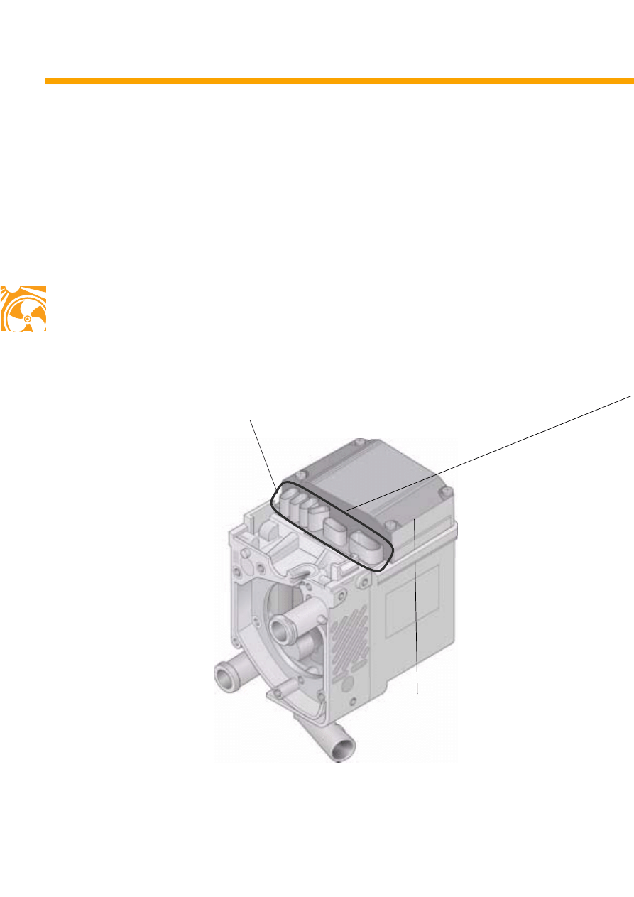
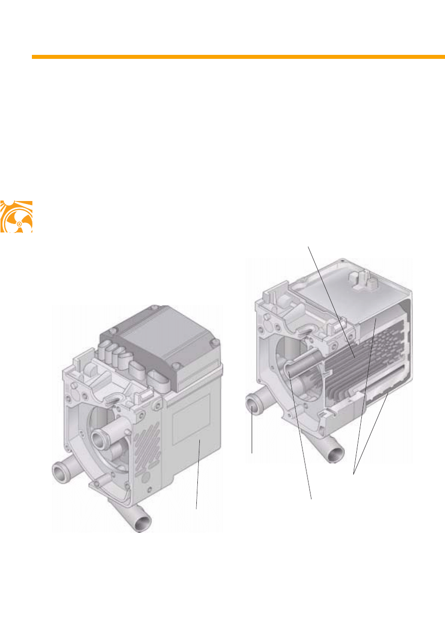
Construction
Control unit
S280_004
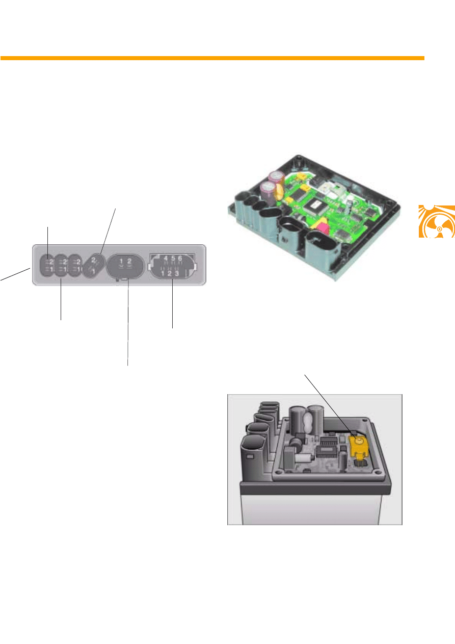
Connector strip
The auxiliary heater control unit J255
Main view
As primary control unit, the control unit guarantees the functional sequence and monitor heater
operation.
Connection to the vehicle onboard electrical system is via a connector strip.
The supplementary heater and the auxiliary heater differ in control unit codes and connection to the
coolant circuit. In addition, the auxiliary heater has a remote start function and a coolant shutoff valve.
17
Temperature monitoring
Coolant temperature is monitored in the heater
and heater operation is regulated via the
temperature sender G241. At coolant
temperatures above 125 °C, the heater is
shut off and locked.
To unlock, follow the instructions on the diagno-
sis, testing and information system VAS 5051 and
the electronic service information system (ELSA).
S280_054
Control unit opened
S280_065
Temperature sender
Glow plug with flame monitor Q9
Power supply
Combustion air blower V6
Recirculating pump V55
Connector to onboard
electrical system
S280_035
18
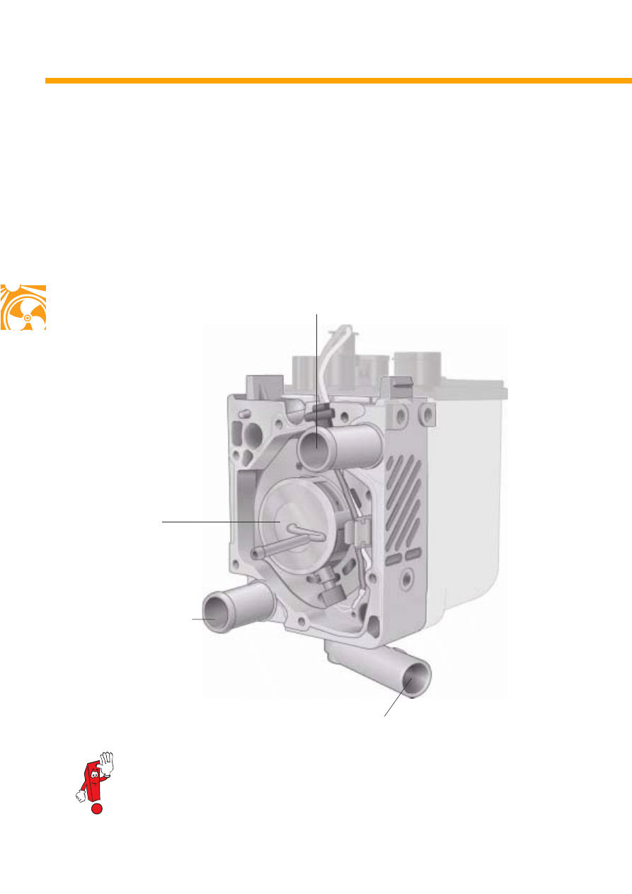
The burner housing
Located on the burner housing are:
- the coolant outlet,
- the exhaust pipe,
- the coolant inlet and
- the combustion chamber.
Construction
Coolant inlet
Coolant outlet
S280_027
Further, the burner housing houses the combustion chamber and forms a unit with the coolant
jacket and the control unit.
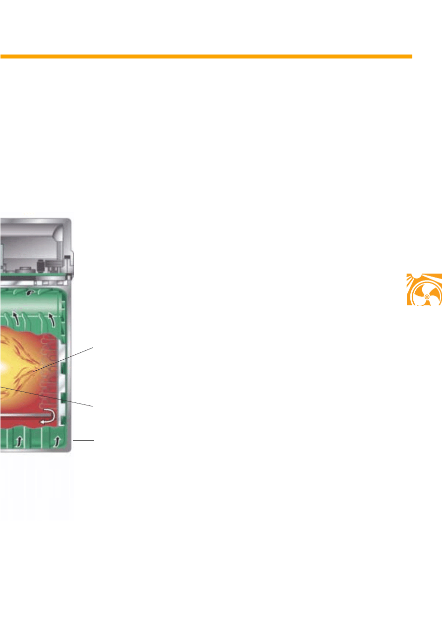
Combustion
chamber
Burner housing
Exhaust pipe
19
Formation of the fuel-air mixture takes place in
the combustion chamber. This mixture is then
burnt in the flame pipe.
The glow plug with flame monitor can be found
in the combustion chamber. This ignites the
fuel-air mixture initially. During the heating
stage, the glowing walls of the combustion
chamber ignite the fuel-air mixture.
The glow plug is designed as an electrical
resistor and features a flame monitor. It monitors
the temperature of the flame during the whole
phase of heating.
Glow plug with flame monitor
S280_005
Combustion air inlet
Combustion air inlet
into
fuel evaporator
Fuel intake
Flame pipe
The combustion chamber with flame
pipe and heater glow plug Q9 (with flame monitor)
Combustion air inlet
Flame pipe
Combustion chamber
Combustion chamber
Combustion chamber cross section
S280_056
20
The coolant jacket.
Construction
Coolant jacket
S280_004
Coolant inlet
Coolant outlet
Space for coolant
(transfer of heat)
Main view
Coolant jacket cross section
Space for combustion chamber
S280_060
The heat generated from combustion is conveyed to the coolant via the coolant jacket.
Coolant enters the housing via the coolant inlet of the coolant jacket (heat transmitter). The necessary
heat is then drawn for heating. Coolant leaves the housing via the coolant outlet.
21
The exhaust system
S280_025
Silencer
Exhaust pipe
The heater features its own exhaust system, which consists of an exhaust pipe and silencer. The exhaust
system channels the exhaust gas generated from heater combustion to the outside independently of the
vehicle exhaust system.
In order to guarantee safe operation of the heater, the prescribed length of the exhaust system should
not be altered.
The length is set to balance the combustion vibrations of the heater.
22
The metering pump V54
Supply of fuel from the fuel tank of the vehicle to
the heater is by metering pump. The pump is
designed as a combined supply, metering and
shutoff system. This means that fuel is metered
during operation and fuel supply is blocked
when the heater is switched off.
Fitting location
The metering pump can be found above the rear
axle. To remove the pump, the rear axle has to be
lowered. In order to ensure correct ventilation of
the pump, the prescribed fitting location must not
be changed.
Actuation
The metering pump is pulse-actuated via the
control unit based on the required heater output.
Construction
S280_014
S280_063
S280_046
23
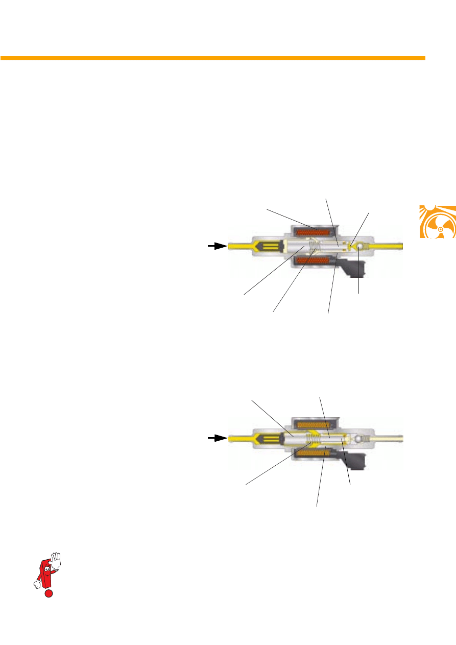
Functional description
The metering pump is of the plunger type, in
which the armature is attached permanently to
the pump plunger.
Supply of fuel
The metering pump is filled with fuel when there
is no voltage.
When the coil is energised, the armature pushes
the pump plunger against the spring.
The pump plunger lifts up the ball valve and
delivers fuel from the pump chamber. At the
same time, the supply hole to the pump chamber
is closed.
Fuel suction
During this period, fuel flows in the armature
chamber. When the coil is not energised, spring
pressure forces the armature and the pump
plunger back.
The resulting vacuum draws fuel into the pump
chamber via the opened inlet holes.
This kind of operation allows a high level of
metering accuracy, high durability and low noise
generation.
S280_067
Coil
Ball valve
Armature
Pump plunger
Spring
Inlet hole
Pump chamber
Armature
chamber
S280_062
Armature
Pump plunger
Pump chamber
Inlet hole
An animated view of the function can be found on the internet at
"www.thomas-magnete.com"
24
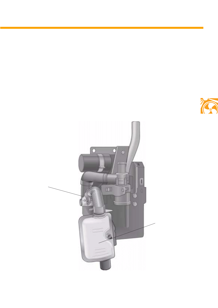
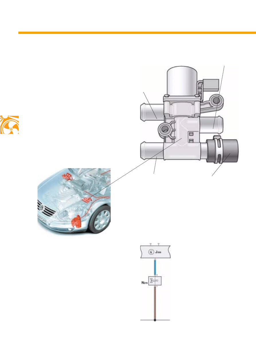
Only the auxiliary heater features a coolant
shutoff valve. When the auxiliary heater is in
operation, engine coolant circulation is
separated from the heat exchangers to the
interior.
Separation is via the coolant shutoff valve.
Fitting location
The coolant shutoff valve can be found on the
left in the engine compartment.
Actuation
The auxiliary heater control unit actuates the
valve directly.
Construction
To engine
From pump valve unit
To heater
S280_016
Plug
S280_064
Coolant shutoff valve N279
S280_048
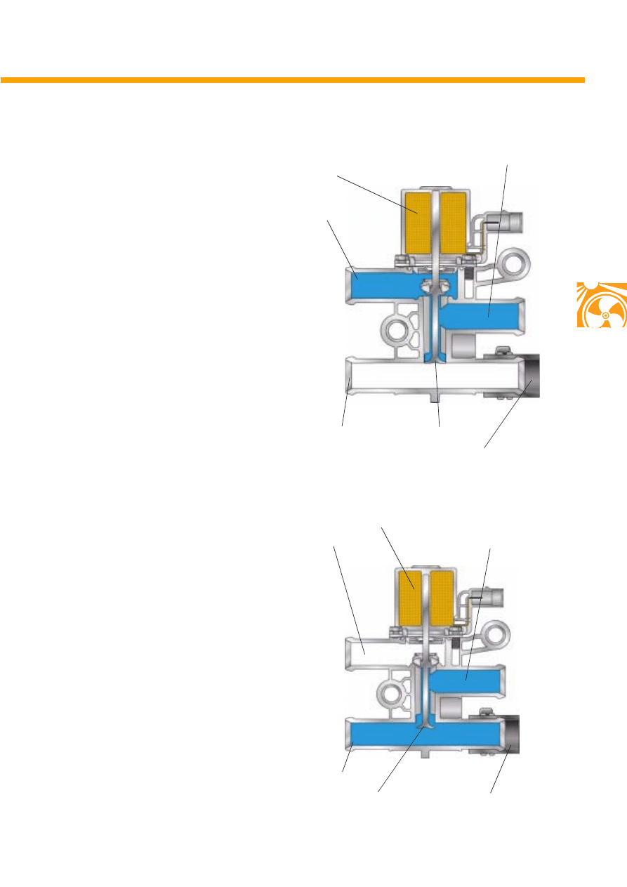
25
Normal operation
When there is no power, the coolant shutoff
valve connects the coolant circuit between the
pump valve unit and engine circuit.
Heater operation
The shutoff valve is actuated and the pump valve
unit is connected with the auxiliary heater.
In this way, the interior of the vehicle is
preheated and not the engine.
To engine
From pump valve unit
Plug
Coil
Valve plunger
To engine
From pump valve unit
To heater
Plug
Coil
Valve plunger
S280_050
S280_051
To heater
26
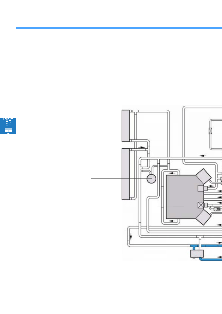
Coolant circuit
Connection of auxiliary heater in coolant circuit of W12 engine
If the auxiliary heater is started when the engine is switched off, the coolant shutoff valve closes.
The recirculating pump pumps coolant through the coolant jacket in the auxiliary heater to the pump
valve unit, then through the heat exchanger inside the vehicle and back to the auxiliary heater.
The vehicle interior is heated.
Gearbox oil cooler
Engine oil cooler
Alternator C
Cylinder block
Coolant circuit
Coolant shutoff valve N279
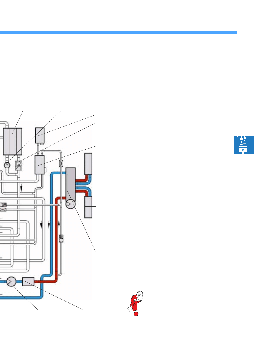
27
Function
When voltage is applied to the shutoff valve, coolant can flow from the pump valve unit to the heater.
When there is no voltage at the shutoff valve, coolant can flow from the pump valve unit to the engine.
Recirculating pump
V55
Auxiliary heater
Pump valve unit
Left heat exchanger
Right heat exchanger
Expansion tank
Air reservoir
Continued coolant circulation pump V51
Thermostat
Radiator
The pump valve unit is part of the
vehicle heater and is described in
SSP 271.
S280_015
28
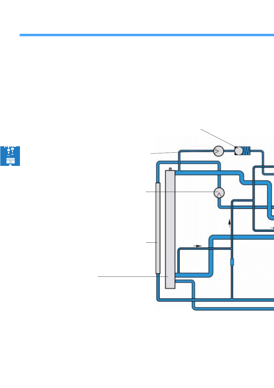
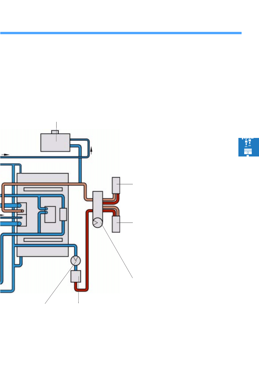
Coolant circuit
Connection of auxiliary heater in coolant circuit of V10 TDI engine
On the supplementary heater there is no coolant shutoff valve. The heater is permanently connected to
the engine coolant circuit.
Coolant circuit
Low temperature cooler for
alternator and fuel cooling
Radiator
Fuel cooling pump V166
Continued coolant circulation pump
V51
Check valve
29
Expansion tank
Right heat exchanger
Left heat exchanger
Pump valve unit
Supplementary heater
S280_052
Recirculating pump
V55
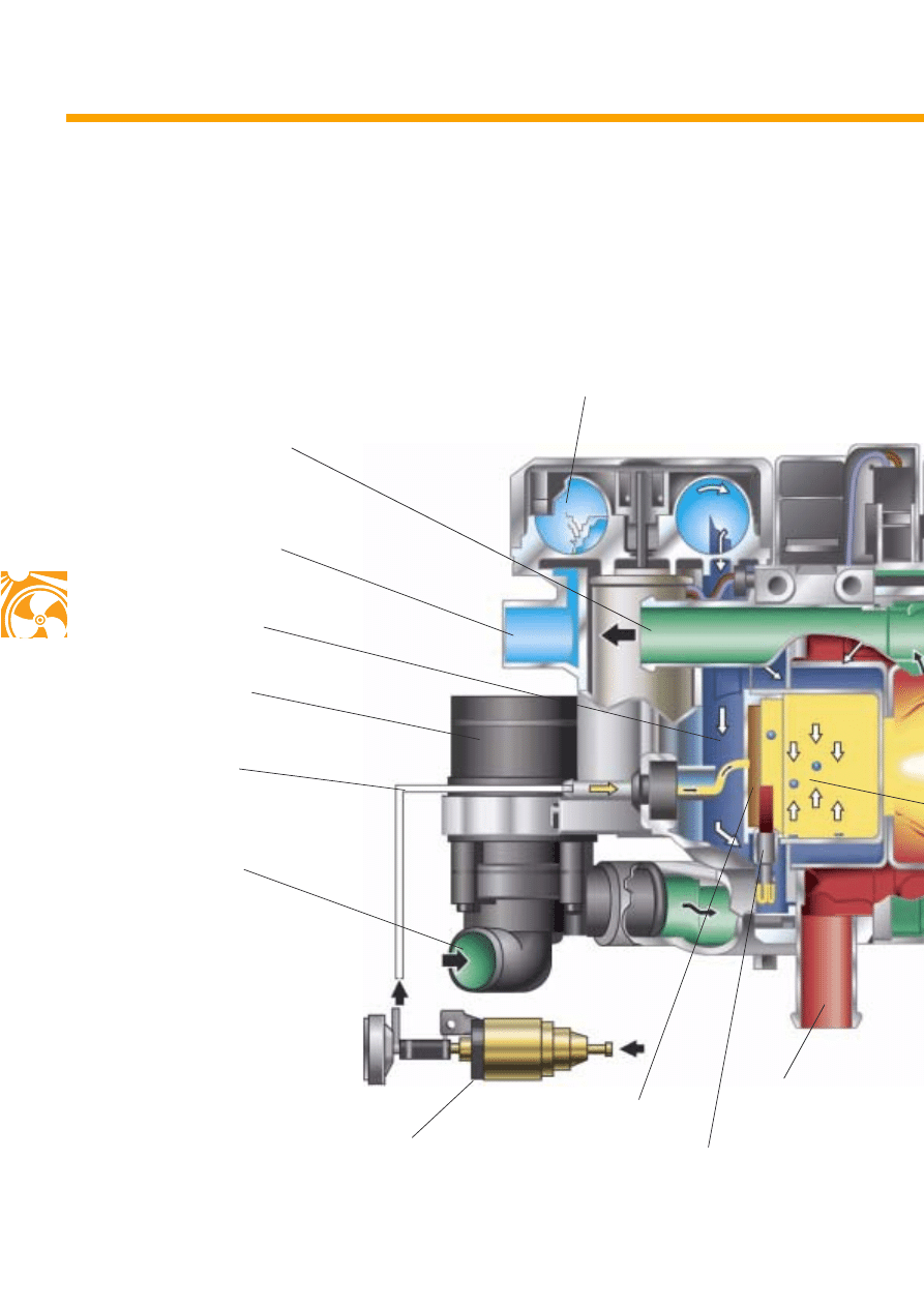
30
Air supply
The air required for combustion is drawn via the
combustion air intake from the combustion air
blower and passed through the combustion air
channel to the combustion chamber.
Function
Combustion air blower V6
Coolant outlet
Combustion air inlet
Fuel channel
Coolant inlet
Metering pump V54
Combustion air channel
Heater glow plug Q9
(with flame monitor)
Fuel evaporator
Exhaust pipe
Recirculating pump V55
31
The fuel supply
Fuel is supplied through the fuel channel. In the
fuel evaporator (fleece), fuel is mixed with the
combustion air, forming a combustible fuel-air
mixture.
The glow plug with flame monitor ignites the
mixture in the combustion chamber at the start.
Once operation has begun, ignition occurs at the
flame front in the flame pipe.
During operation of the heater, the glow plug Q9
is supplied with only a small amount of energy
from the control unit.
The electrical resistance of the glow plug can
thus be used as a flame monitor.
The coolant
Coolant enters through the coolant inlet in the
coolant jacket. Here, it is heated. The heated
coolant flows out the coolant outlet into the
coolant circuit.
S280_010
Coolant jacket
Flame pipe
Combustion chamber
in burner housing
32
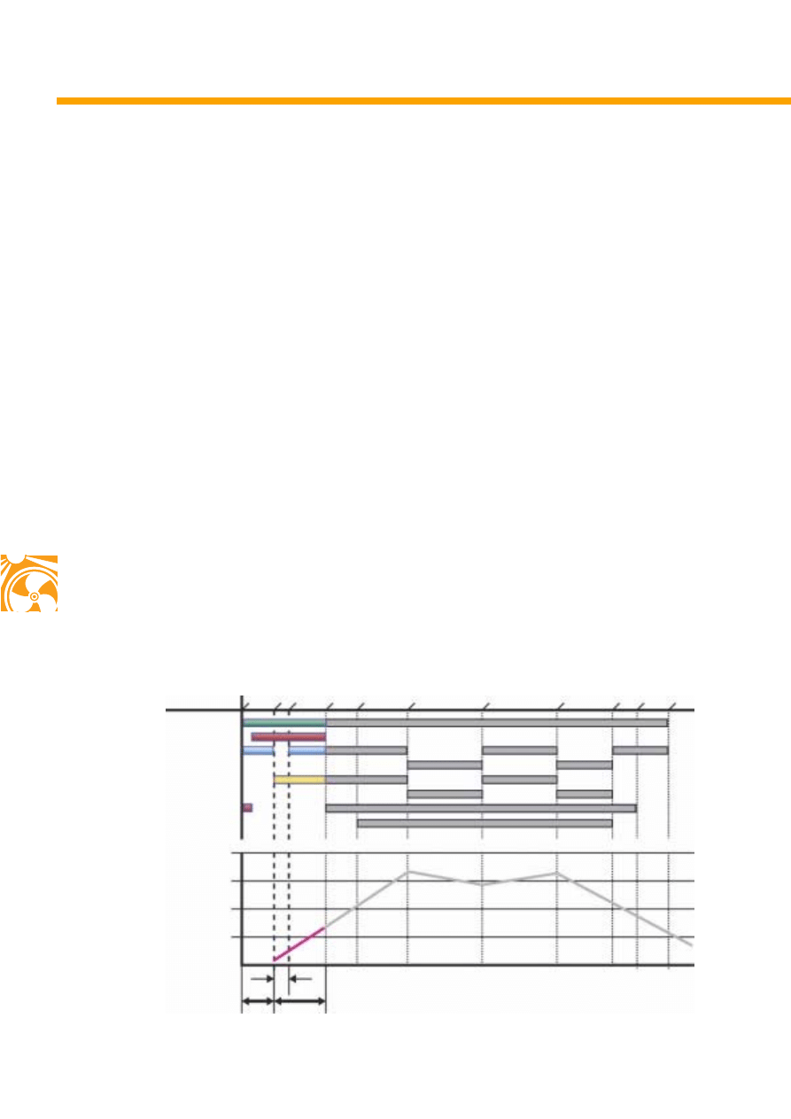
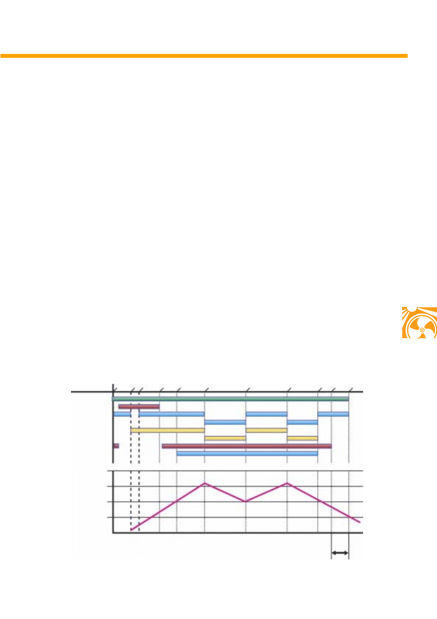
The auxiliary heater
Start phase
The auxiliary heater is started either:
- immediately,
- via the timer or
- using the remote control.
The combustion air blower and the recirculating
pump are actuated.
The glow plug starts to glow and the combustion
air blower pumps air into the burner insert.
After about 30 seconds, the metering pump
starts to deliver fuel and the combustion air
blower is switched off for about 5 seconds until
a rich mixture has built up.
The output of the combustion air blower is
increased in stages to full load and the fuel-air
mixture is delivered to the combustion chamber.
Combustion begins.
If no flame is formed or the flame dies, restart is
initiated automatically. After a total of
90 seconds of fuel delivery without flame
formation, the system is switched off until the
ignition is switched on again (terminal 15).
Metering pump TL
Operating stages
Glow plug
Recirculating pump
Combustion air blower TL
Combustion air blower VL
Fresh air blower
Metering pump VL
Flame monitor interrogation
Temperature in °C
90
85
80
75
70
5
30
90
Time in seconds
St
ar
t
Sta
rt
of
com
bu
stio
n
Ful
l l
oad oper
at
ion
Fre
sh
ai
r blower
Pa
rt
load
Ful
l load
Sh
ut
of
f
Pa
rt l
oa
d
Sta
rt o
f ru
n-
on
End
of
run-
on
S280_036
Pr
eg
low
33
Heating phase/regulated phase
When the coolant reaches a temperature of
87 °C, the heater is switched from full load to
part load. This reduces the combustion air
blower output and the metering pump delivers
less fuel. If the coolant temperature drops to
approx. 83 °C, full load is activated again.
At a coolant temperature of approx. 89 °C,
heating is interrupted. When the coolant
temperature drops to approx. 85 °C, heating is
initiated once again.
Temperature in °C
90
85
80
75
70
S280_037
Sta
rt
St
ar
t o
f co
m
bu
stio
n
Fu
ll l
oad
oper
at
ion
Fr
es
h ai
r blow
er
Pa
rt
load
Ful
l l
oad
Sh
uto
ff
Pa
rt l
oa
d
St
ar
t o
f ru
n-
on
En
d of
ru
n-
on
Pr
eg
lo
w
Metering pump TL
Glow plug
Recirculating pump
Combustion air blower TL
Combustion air blower VL
Fresh air blower
Metering pump VL
Flame monitor interrogation
34
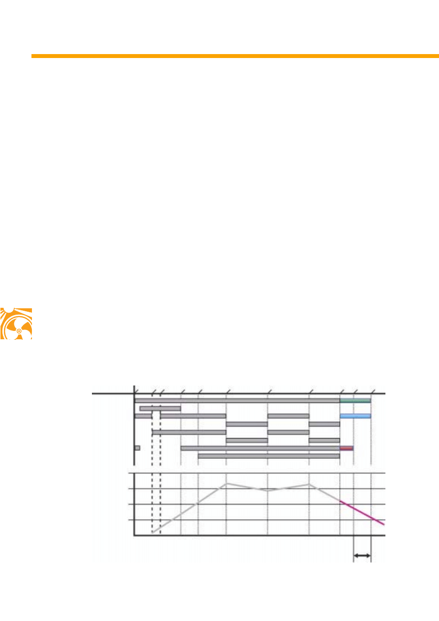
Run-on phase
The auxiliary heater is deactivated by:
- switching off the engine,
- switching off the auxiliary heater or
- expiration of the automatic heating duration
(max. 60 minutes).
The metering pump is switched off, combustion
stops, the combustion air blower and the
recirculating pump run-on to cool down and are
then switched off automatically.
Run-on time depends on the type of heater and
can be between 100 and 175 seconds.
The run-on time for petrol-driven heaters is:
●
168 seconds when switched off from full load
●
157 seconds when switched off from part load
The run-on time for diesel-driven heaters is:
●
175 seconds when switched off from full load
●
100 seconds when switched off from part load
There may be slight deviations in the given
figures depending on the development of the
software.
Operating phases
Temperature in °C
85
80
70
60
50
Time in seconds
100 - 175
S280_038
Metering pump TL
Glow plug
Recirculating pump
Combustion air blower TL
Combustion air blower VL
Fresh air blower
Metering pump VL
Flame monitor interrogation
St
ar
t
St
ar
t of
com
bu
sti
on
Fu
ll
load oper
at
io
n
Fre
sh
a
ir
bl
ow
er
Pa
rt l
oa
d
Ful
l l
oad
Sh
ut
of
f
Pa
rt
load
Sta
rt
of
ru
n-
on
End of
ru
n-
on
Pr
eg
lo
w
35
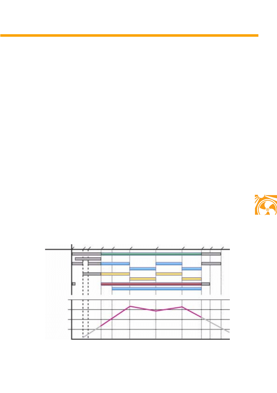
The supplementary heater
(diesel engines)
Start phase
When the engine is started, the heater is made
ready.
When the coolant temperature is below 60 °C,
ambient temperature is below + 5 °C and the
control unit has received an engine speed signal,
start is initiated.
Heating phase
If the coolant reaches 78 °C, operation is
interrupted. When the coolant temperature
reaches 76 °C, full load operation is switched to
part load. The transition from part load to full
load comes at 70 °C and to part load at 65 °C.
Run-on phase
When the engine is switched off, the
supplementary heater is stopped.
Combustion is stopped and run-on begins.
The supplementary heater run-on time is:
●
175 seconds when switched off from full-load
●
100 seconds when switched off from part-load
There may be slight deviations in the given
figures depending on the software version.
Temperature in °C
80
75
70
60
50
Time in seconds
S280_020
Sta
rt
St
ar
t o
f co
m
bu
stio
n
Fu
ll l
oad
oper
at
ion
Fr
es
h ai
r blow
er
Pa
rt
load
Ful
l l
oad
Shut
off
Pa
rt l
oa
d
St
ar
t of
ru
n-
on
En
d of
ru
n-
on
Pr
eg
lo
w
Metering pump TL
Glow plug
Recirculating pump
Combustion air blower TL
Combustion air blower VL
Fresh air blower
Metering pump VL
Flame monitor interrogation
100 - 175
36
Deactivation
The auxiliary heater and the supplementary
heater are switched off for reasons of safety
under certain conditions.
Vehicle-specific deactivation
The auxiliary heater is switched off when:
- the tank flap is opened,
- the fuel level is low,
- the onboard electrical system is placed under
heavy load by the onboard electrical system
control unit,
- an airbag is triggered by an accident
- heater output is sufficient during normal
driving.
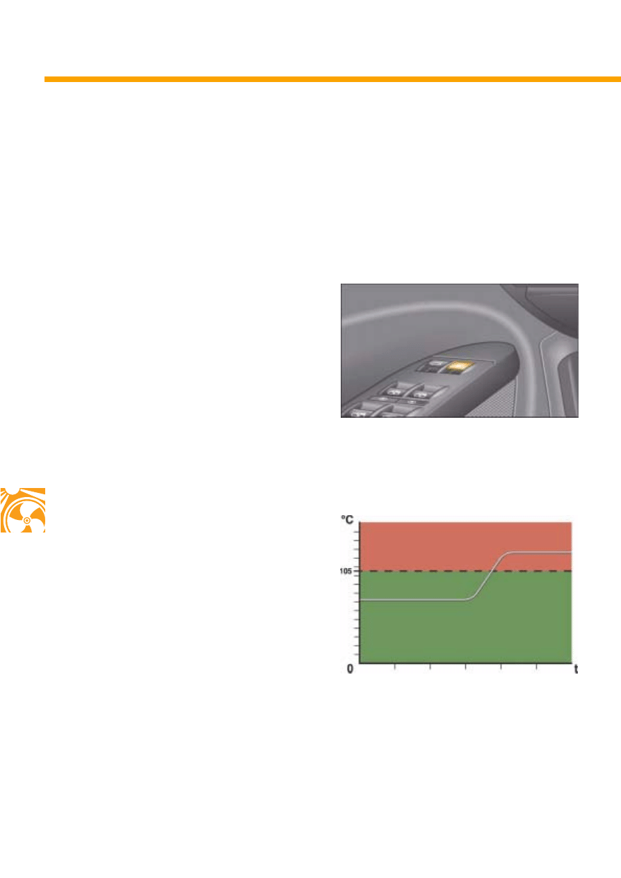
Temperature related deactivation
If the coolant temperature rises above 105 °C
during heater operation, fuel supply is
interrupted.
In this instance, the heater will run-on for
approx. 120 seconds. If there is a fault in the
combustion air blower, there will be no run-on.
S280_028
Deactivation conditions
S280_024
Heater operation
Deactivation
37
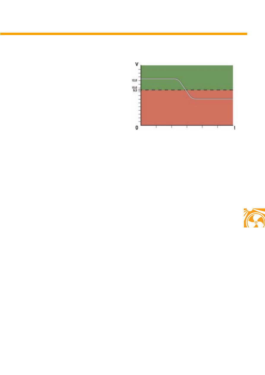
Deactivation due to excessive or insufficient
voltage
In addition to monitoring of the onboard
electrical system voltage by the onboard
electrical system control unit, the auxiliary heater
control unit also deactivates the heater if
excessive or insufficient voltage is detected.
Fixed deactivation due to insufficient voltage
If the battery voltage drops to below 9.5 volts for
longer than 6 seconds, the heater is deactivated
with a run-on time of 120 seconds.
Deactivation due to excessive voltage
If the battery voltage exceeds 15.5 volts for more
than 60 seconds, the auxiliary heater is
deactivated.
S280_029
Heater operation
Deactivation
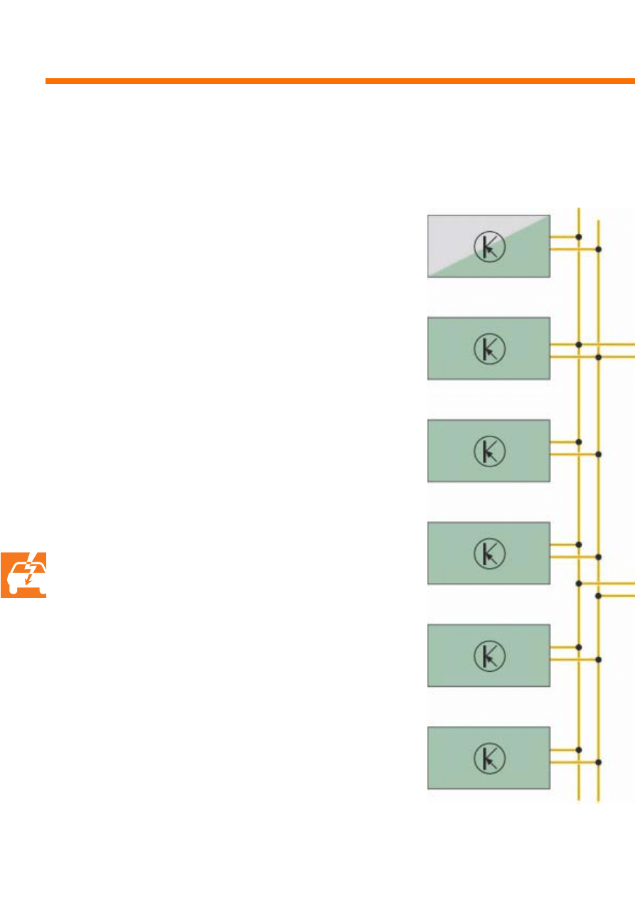
38
The auxiliary heater control unit is connected
with the other control units in the vehicle via the
infotainment CAN data bus and the diagnosis
data bus interface in the dash panel. All the
necessary information can be exchanged with
other control units via this data network.
Networking
Control unit for front informa-
tion display and operating
unit
Communication via CAN data bus
Roof electronics control unit
J528
Climatronic/air conditioning control unit
J301
Onboard electrical supply control unit J519
Entry and start authorisation control unit J518
Door control unit, driver side
J386
Climatronic operating and control unit
E265
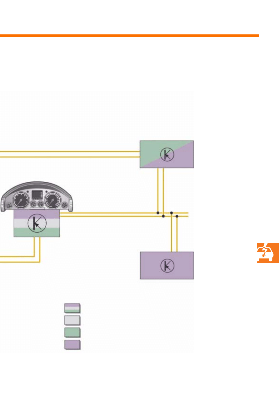
39
Auxiliary heater control unit
J255
Drive train CAN data bus
Convenience CAN data bus
Infotainment CAN data bus
S280_034
Data bus diagnosis interface
Control unit for front information
display and control unit
J523
Data bus diagnosis interface
J533
in dash panel

40
The data bus messages
A) Function
B) Message
Auxiliary heater messages received from remote
commands and from modes of operation
Activation via remote control
Activation of blower
Activation of control LED
Commands and information to auxiliary heater control
unit
Activation of auxiliary heater
Tank warning on
Convenience CAN data bus messages
Terminal information
Ignition on
Auxiliary heater operation
Operating commands
e.g. auxiliary ventilation
e.g. immediate start
Auxiliary heater operation
Auxiliary heater operating mode
Heating duration
Programming of auxiliary heater
Start time
Actuation of auxiliary heater
Auxiliary heater operating mode
Auxiliary heater duration information
Auxiliary heater duration
Heater deactivation
Tank flap opened
Heater deactivation
Onboard electrical system critical battery level
Heater deactivation
Crash impact signal
Status information
Engine speed
Ambient temperature
Engine type
Networking
41
C) Sender
D) Receiver
Auxiliary heater control unit
Control unit with display unit in dash panel insert
Climatronic/air conditioning control unit
Roof electronics control unit
Entry and start authorisation control unit
Onboard electrical supply control unit
Control unit for front information display and
operating unit
Climatronic/air conditioning
operating and display unit
Control unit with display unit in dash panel insert
Additional water heater control unit
Control unit with display unit in dash panel insert
Auxiliary coolant heater control unit
Control unit with display unit in dash panel insert
Auxiliary heater control unit
Climatronic/air conditioning control unit
Control unit for front information display and
operating unit
Control unit with display unit in dash panel insert
Control unit for front information display and
operating unit
Control unit with display unit in dash panel insert
Climatronic/air conditioning control unit
Climatronic/air conditioning
operating and display unit
Control unit with display unit in dash panel insert
Control unit for front information display and
operating unit
Control unit with display unit in dash panel insert
Climatronic/air conditioning control unit
Door control unit, driver side
Control unit with display unit in dash panel insert
Onboard electrical supply control unit
Control unit with display unit in dash panel insert
Control unit with display unit in dash panel insert on
receipt of message from airbag control unit
Auxiliary heater control unit
Control unit with display unit in dash panel insert
Additional coolant heater control unit
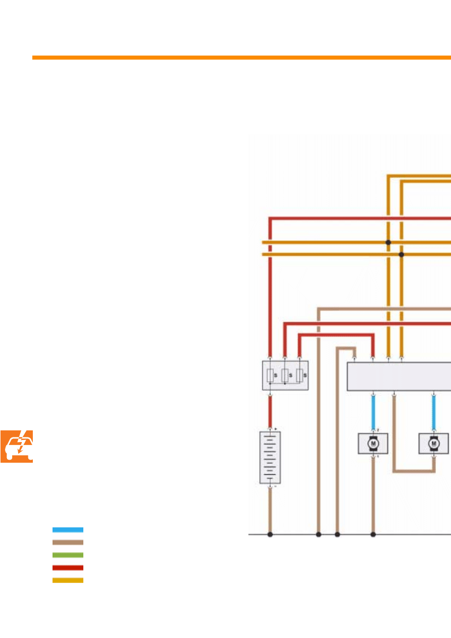
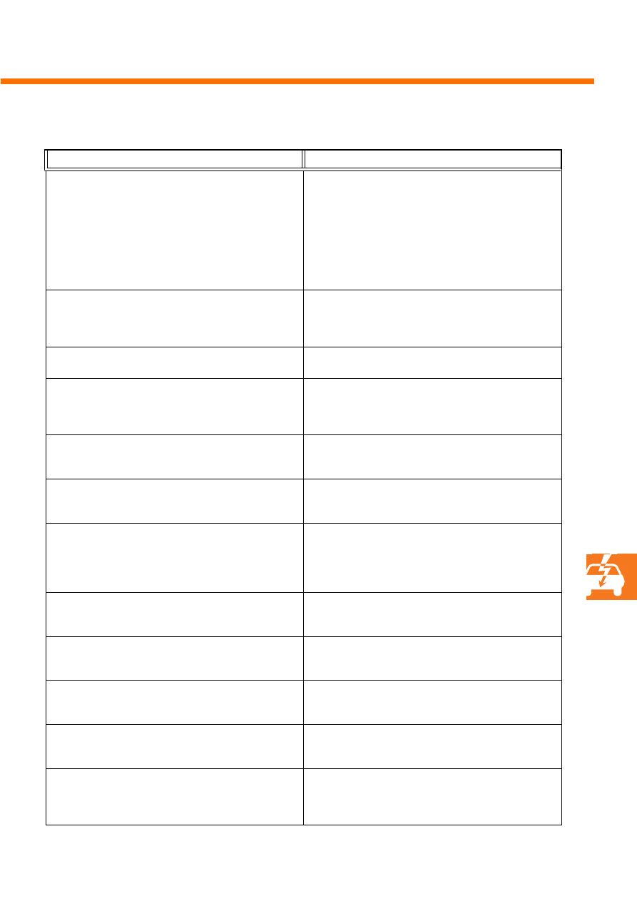
42
Functional diagram
Key
A
Battery
G241 Coolant temperature sender, heater
J255 Auxiliary heater control unit
on auxiliary heater
J285 Control unit with display unit in
dash panel insert
J533 Data bus diagnosis interface
N279 Coolant shutoff valve, heater
Q9
Heater glow plug Q9
(with flame monitor)
R11
Aerial
R149 Auxiliary heater remote receiver,
beneath rear shelf
S
Fuse
V6
Combustion air blower
V54 Metering pump
V55 Recirculating pump
Y
Analogue clock
Signal output
Earth
Signal output
Positive
Infotainment CAN data bus
A
V54
V55
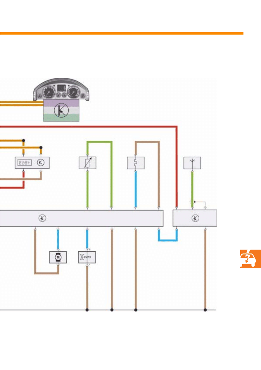
43
S280_043
V6
N279
J255
R149
Y
G241
Q9
R11
J533
J285
44
Diagnosis
Diagnosis can be carried out using the
testing and diagnosis system VAS 5051.
Communication is via the diagnosis interface.
The exchange of data between the diagnosis
system and the diagnosis interface in the dash
panel insert is via the COM lead.
Continued exchange of data is via the
infotainment CAN data bus.
If the data bus is defective or the data bus
diagnosis interface
is defective, diagnosis is not possible.
A description of the individual diagnosis
functions can be found in the guided fault
finding program on the testing and diagnosis
system VAS 5051. These are accessed
automatically.
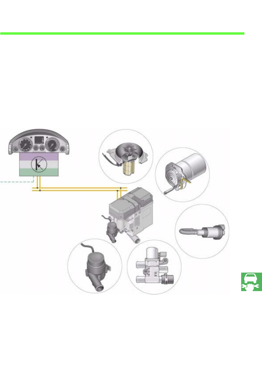
The following components are monitored by the
diagnosis system:
●
Auxiliary heater control unit
●
Combustion air blower
●
Glow plug
●
Metering pump
●
Coolant shutoff valve
●
Recirculating pump
Additionally, the power supply and data bus
communication are checked and any faults are
stored in the fault memory.
Service
Testing and diagnosis system VAS 5051
45
S280_018
Combustion air blower
Glow plug
Metering pump
Shutoff valve
Recirculating pump
Data bus diagnosis interface

46
Diagnosis interface
The diagnosis interface is a virtual control unit in
the dash panel insert. It transmits CAN data bus
messages from one CAN data bus to the next
and also transmits data from the COM lead to
the CAN data bus lines
Loose belt
The distance between the seat belt and the upper
body (thorax).
The heavier the clothing, the greater the distance
between upper body and
seat belt. This distance has to be balanced by the
belt tensioner in a collision.
Degree of efficiency
The relationship between the energy supplied
and energy returned. The chemical energy
stored in the fuel is converted partly into
mechanical energy and thereby into kinetic
energy.
The remaining energy ends up as heat,
exhaust gas and radiant energy.
Glossary

47

48
1. The auxiliary heater is activated
a) automatically when the ignition is switched on.
b) by the on/off switch in the driver's door.
c) by the immediate start function in the information display and operating unit.
2. The fixed start time is programmed
a) by the timer preselection in the front information display and operating unit.
b) by the preselection clock in the driver's door.
c) by the analogue clock setting in the dash panel insert.
3. Remote start
a) is initiated by dialing telephone number 0800 89 73 74 23 and giving the start time to the
centre.
b) is initiated by pressing the start button on the remote control.
c) is initiated by pressing the open button on the ignition key.
4. When the engine is not running, the auxiliary heater heats
a) the engine.
b) the interior via the pump valve unit and the left and right heat exchangers.
c) the interior via the pump valve unit and the left and right heat exchangers,
the luggage compartment and the engine.
Test yourself

49
5. In the start phase of auxiliary heating
a) the combustion air blower is switched off for 5 seconds so that a rich mixture is
created.
b) the metering pump is increased to 150 % delivery so that a rich mixture is created.
c) the combustion air blower delivers more air to create a leaner mixture.
6. The auxiliary heater is switched off if
a) during the start phase there is no independent flame.
b) the coolant temperature rises above 105 °C.
c) the battery voltage is less than 9.5 volts for six seconds.
7. The auxiliary heater control unit
a) communicates with other control units in the vehicle via the drive train CAN data bus.
a) communicates with other control units in the vehicle via the convenience CAN data bus.
c) communicates with other control units in the vehicle via the infotainment CAN data bus and
data bus diagnosis interface in the dash panel insert.
Answ
ers
1c; 2a; 3
b; 4
b; 5
a;
6a
,b,c; 7
c;

50
Notes

51
For internal use only © VOLKSWAGEN AG, Wolfsburg
All rights and the right to make technical alterations reserved
240.2810.99.20 Technical status 02/03
❀
This paper was manufactured from pulp that
was bleached without the use of chlorine.
280
Wyszukiwarka
Podobne podstrony:
Self Study Programme 276 Phaeton automatic proximity control
Self Study Programme 365 4 2L V8 with common rail
Self Study Programme 388 4 2L V8 4V FSI engine
Self Study Programme 431 Audi RS 6
Self Study Programme 17 Octavia convenience electronic system
Self Study Programme 279 2 0L 110kw with petrol direct injection FSI
Self Study Programme 189 2 3L petrol engine in the LT 97
Self Study Programme 376 5 2 litre V10 FSI engine
Self Study Programme 396 Lane change assist
Self Study Programme 351 Common rail fuel injection system fitted in the 3 0l V6 TDI engine
Self Study Programme 288 Audi A8 03 distributed functions
Self Study Programme 398 Audi lane assist
Programmed repair Auxiliary heater Part C Models 124, 126 020 024 025
Programmed repair Auxiliary heater Part C Models 124, 126 020 024 025
0400 Function description B Operating principle with function diagram Auxiliary heater Models 124,
0402 Arrangement of components Auxiliary heater A Model 124
0400 Function description auxiliary heater A General Models 124, 126, 201
więcej podobnych podstron