Engineering
23.11.2016
1 (17)
AMEC FOSTER WHEELER ENERGIA POLSKA Sp. z o.o.
ul. Chmielna 85/87, 00-805 Warszawa
ul. Chmielna 85/87, PL 00-805 Warsaw, Poland
Tel. 022 581 0036, Fax 022 581 0958
Tel. +48 22 581 0036, Fax +48 22 581 0958
Biuro w Sosnowcu:
Office in Sosnowiec:
ul. Staszica 31, 41-200 Sosnowiec
ul. Staszica 31, PL-41200 Sosnowiec, Poland
Tel. 032 3681517, Fax 032 266 9777
Tel. +48 32 3681517, Fax +48 32 266 9777
Siedziba firmy: Warszawa, KRS 0000065443
Domicile Warsaw, Business ID 0000065443
Project:
FGT for
FORTUM Częstochowa – Poland
Subject:
INVITATION TO BID
– System – Fly Ash Handling System
Author:
Tomasz Ortman
Checked by:
Michał Mączko
Approved by:
Anna
Jasińska
Customer:
FORTUM Częstochowa
Customer reference:
Action:
Invitation to offer
Other information:
Revision remarks
Revision: Revision date: Revised information:
Pages:
Revised
by:
Checked
by:
Approved
by:
0
10.11.2016
Original document
16
ORT
MMA
ADJ
1
23.11.2016
Revised document
17
AST
MMA
ADJ

Engineering
23.11.2016
2 (17)
TABLE OF CONTENTS:
1
GENERAL ................................................................................................................................... 3
2
MECHANICAL ............................................................................................................................ 3
2.1
CE-Marking ................................................................................................................................. 3
3
MECHANICAL ............................................................................................................................ 3
4
SITE CONDITIONS ..................................................................................................................... 4
5
STANDARDS, RULES AND RECOMMENDATIONS ................................................................ 4
6
DESIGN DATA ........................................................................................................................... 5
6.1
Fabric Filter Data ......................................................................................................................... 5
6.2
Boiler Fly Ash Analysis................................................................................................................ 5
6.3
Boiler Fly Ash Particle Size Distribution ...................................................................................... 5
6.4
Final Fly Ash Composition (at the Fabric Filter Hoppers outlets) ............................................... 6
6.5
Compressed air ........................................................................................................................... 6
7
EQUIPMENT SPECIFICATION .................................................................................................. 6
7.1
Fly ash handling system
– separate pneumatic transmitters ...................................................... 8
7.2
Fly ash handling system
– common cumulative collector ........................................................... 9
7.3
Fly ash handling system
– chain conveyor ............................................................................... 10
7.4
Instrumentation and Control Equipment
– requirements .......................................................... 11
7.5
NTE Loads ................................................................................................................................ 11
7.6
Operation and Performance ...................................................................................................... 11
8
SCOPE OF SUPPLY ................................................................................................................ 11
9
DELIVERY LIMITS ................................................................................................................... 13
10
CONTENT OF THE OFFER ..................................................................................................... 13
10.1
Pricing ....................................................................................................................................... 14
11
PERFORMANCE AND OPERATION GUARANTEES ............................................................ 14
11.1
Time of Guarantee .................................................................................................................... 14
11.2
The following values should be guaranteed:............................................................................. 14
11.3
Vibration .................................................................................................................................... 15
11.4
Noise ......................................................................................................................................... 15
11.5
Avaliability ................................................................................................................................. 16
11.6
Documentation .......................................................................................................................... 17
12
ENCLOSURES ......................................................................................................................... 17

Engineering
23.11.2016
3 (17)
1
GENERAL
Overall, the European standards and codes are preferred in the engineering, design,
manufacturing, supervising of erection and erection of all equipment.
Mechanical equipment shall be designed according to EN/PED standards. Electrical equipment
and installations shall be designed and built in accordance with the IEC norm and regulation valid
in Poland.
2
MECHANICAL
The equipment shall be designed to conform to the provisions of ISO Standards and valid safety
regulations.
Special attention is paid to reliability and ease of maintenance.
The equipment shall be safe in use, successfully proven in power plants and correctly dimensioned
to its operation. The delivery and equipment shall meet the environmental and technical
requirements of the applicable directives and harmonized standards. Additionally, health and safety
requirements and the functional safety of safety related systems (IEC 61508), ATEX-requirements
etc. shall be fulfilled.
2.1 CE-Marking
Compliance has to be demonstrated by CE marking affixed to the equipment and supported by EC
declaration of conformity signed by the manufacturer or his representative within the community.
CE marking carries a presumption of compliance with the requirements of relevant directives. In
case the pressure equipment directive (PED) is applied, a reference to EC type examination
certificate, EC design-examination certificate or EC certificate of conformity is required. The
Contractor is responsible to select his equipment and documentation in respect of the categories
of conformity assessment. CE marking on an electronically controlled and electrically powered
machine shall indicate compliance with the applicable directives. The technical documentation shall
show the directives that have been applied.
3
MECHANICAL
This specification outlines the basic requirements for a Fly Ash Handling System and accessories
to be designed, manufactured, inspected, tested and delivered for use with an industrial air
pollution control system for Amec Foster Wheeler Energia Polska.
The Fly Ash Handling System is dedicated for the new Fabric Filter.

Engineering
23.11.2016
4 (17)
4
SITE CONDITIONS
Site
-
Site location
Czestochowa,
Poland
-
Elevation above sea level
m
260
Ambient air
-
Pressure
mbar
984
-
Temperature, annual average
C
8
-
Temperature, minimum
C
-20
-
Temperature, maximum
C
30
Relative Humidity:
-
Annual average
%
75
-
Minimum
%
35
-
Maximum
%
100
Characteristically load of Wind
Pa
250
Characteristically load of Snow
kN/m
2
0.7
Rain data
mm/year
678
5
STANDARDS, RULES AND RECOMMENDATIONS
The delivery and the equipment in it are designed to meet the requirements of the following codes
and standards valid at proposal date in Poland. Following codes and standards will be used:
-
Pressure part design,
manufacturing, inspections and
testing according to:
EU PED (2014/68/EC), EN Standards: EN12952,
EN13445 or AD 2000, EN13480.
The Contractor is responsible for conformity in
accordance with local laws, regulations, standards
and requirements by local authorities including
acceptance by local authorities.
In case the requirements of the laws, regulations,
standards or requirements by local authorities
regarding manufacturing, inspections and testing are
more restrictive than the requirements said in the
PED (2014/68/EC), EN12952, EN13445 or AD 2000,
EN13480 the Purchaser is responsible for conformity
and acceptance by authorities of those.
-
Machinery
Machinery Directive 2006/42/EC
-
Electrical equipment
IEC or ISO
-
Automation
VDI/VDE recommendations
-
P&I Diagrams
DIN-EN ISO 10628 Flow diagrams for process
plants - general rules
-
Civil/Steel Structures
EURONORM
-
Unit-system
SI-system and unit derived from it (bar means
overpressure unless marked otherwise)
-
Coding system
KKS, according to Purchaser KKS book
Engineering
23.11.2016
5 (17)
6
DESIGN DATA
6.1 Fabric Filter Data
Number of compartments:
5
Compartment (module) dimensions (width x depth):
4 m x 7.5 m
Distance between hoppers:
about 4 meters
Distance between hopper outlet and ground surface:
about 3 meters
Hopper outlet size:
300 mm x 300 mm
Amount of hoppers:
5
Hoppers enclosure:
Yes, 4 sided
Volumetric density fly ash:
800 kg/m
3
Structural density fly ash:
1500 kg/m
3
Operating temperature:
140
°C (peak 180°C)
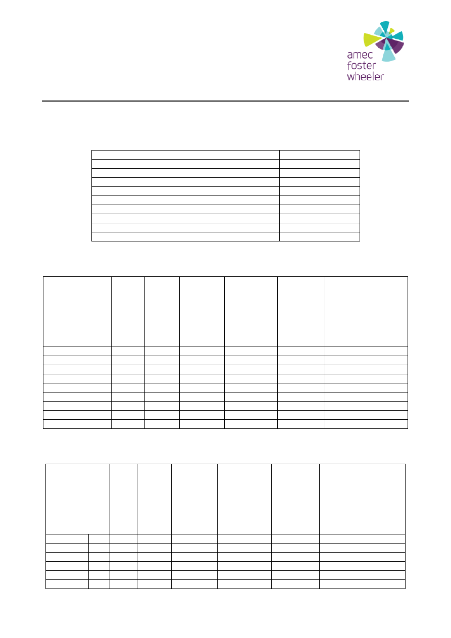
6.2 Boiler Fly Ash Analysis
1 -
100%
MCR
nominal
coal
9
– 100%
MCR
worst coal
(max ash
Cl S, min
LHV)
2
– 100%
MCR
nominal
coal /
nominal
RDF
–
guarantee
point
25
– 100%
MCR
nominal
coal / min
LHV RDF
20 - 100% MCR
worst coal (max ash
Cl S, min LHV) / worst
RDF (max ash Cl S
Hg, min LHV)
CaCO3
wt-%
1.85
2.60
1.25
1.41
2.53
CaO
wt-%
15.38
15.48
12.58
12.45
14.05
MgO
wt-%
1.64
1.57
2.16
2.18
2.04
MgCO3
wt-%
0.08
0.10
0.11
0.14
0.20
CaSO4
wt-%
11.58
13.22
11.61
11.55
16.67
Inert
wt-%
0.41
0.44
0.50
0.49
0.66
Fuel Ash
wt-%
62.88
61.62
66.47
66.52
60.07
Unburned carbon
wt-%
6.18
4.97
5.33
5.27
3.78
Na equivalent
wt-%
0.00
0.00
0.00
0.00
0.00
6.3 Boiler Fly Ash Particle Size Distribution
Fly Ash PSD
1 -
100%
MCR
nominal
coal
9
– 100%
MCR worst
coal (max
ash Cl S,
min LHV)
2
– 100%
MCR
nominal
coal /
nominal
RDF
–
guarantee
point
25
– 100%
MCR
nominal
coal / min
LHV RDF
20 - 100% MCR worst
coal (max ash Cl S,
min LHV) / worst RDF
(max ash Cl S Hg, min
LHV)
< 63
µm
wt-%
71.54
71.79
70.24
70.04
70.90
63-125
µm
wt-%
22.06
22.26
22.92
22.97
23.29
125-180
µm
wt-%
4.90
4.66
5.26
5.36
4.60
180-500
µm
wt-%
1.50
1.29
1.58
1.64
1.21
500-2000
µm
wt-%
0.00
0.00
0.00
0.00
0.00
>2000
µm
wt-%
0.00
0.00
0.00
0.00
0.00

Engineering
23.11.2016
6 (17)
6.4 Final Fly Ash Composition (at the Fabric Filter Hoppers outlets)
Flue Gas Treatment Installation will include Dry Sorbent Injection System (DSI) and Activated
Carbon Injection System (ACI) so the final Fly Ash Composition at Fabric Filter Hoppers outlets will
include also the products of these systems.
The maximum content of DSI product in the final Fly Ash Composition will be 15.5 weight %.
Composition of DSI product:
unreacted Ca(OH)
2
(mostly)
CaSO
3
∙1/2 H
2
O
CaSO
4
∙2 H
2
O
CaCl
2
(also a significant share)
6.5 Compressed air
Parameters of compressed air supplied by Customer:
-
Pressure
bar
7.3
– 7.6
-
Dew point
° C
-20
7
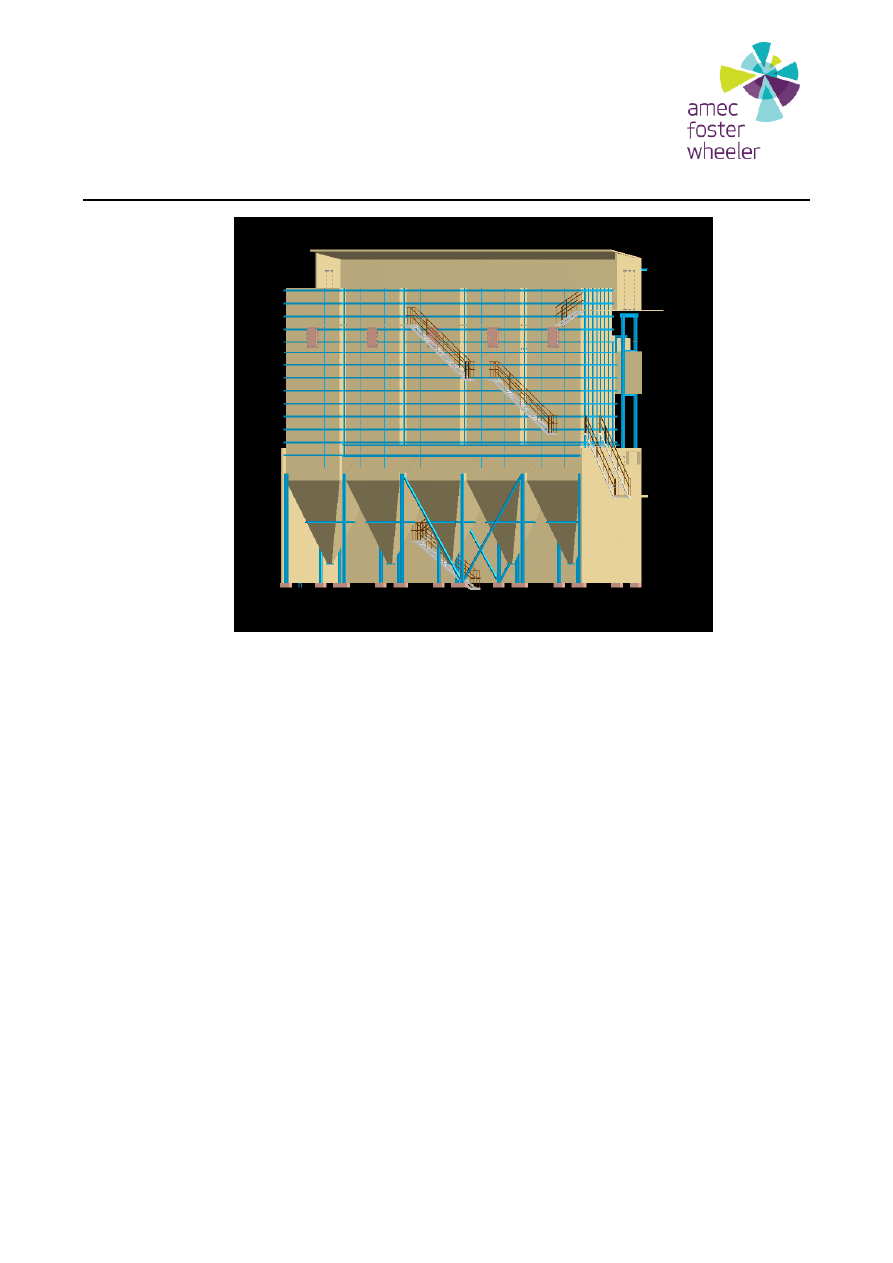
EQUIPMENT SPECIFICATION
Fly Ash Handling System will be provided for fly ash discharging from fabric filter hoppers to existing
fly ash silo.
Fabric Filter is equipped with five hoppers. The distance between hoppers outlets is around 4 (four)
meters. The distance between surface (ground) and outlet of the individual hopper equals 3 (three)
meters.
Engineering
23.11.2016
7 (17)
There are three possible ways to design this system:
First – each fabric filter hopper will be equipped with its own pneumatic transmitter. There
will be five separate discharging lines from fabric filter hoppers to one inlet box at the silo
top.
Second – each fabric filter hopper will be connected to the common cumulative collector
and from this collector fly ash will be transported to the fly ash silo (inlet box at the silo top).
Third – each fabric filter hopper will be connected to the chain conveyor and from this chain
conveyor fly ash will be transported to the fly ash silo (inlet box at the silo top).
Fly ash from fabric filter may be discharged to the fly ash silo only with pneumatic transport (positive
displacement).
There are also two possible options for transportation air supply:
The Contractor will use compressed air supplied by Client.
The Contractor will use additional blowers for fly ash transportation.
Engineering
23.11.2016
8 (17)
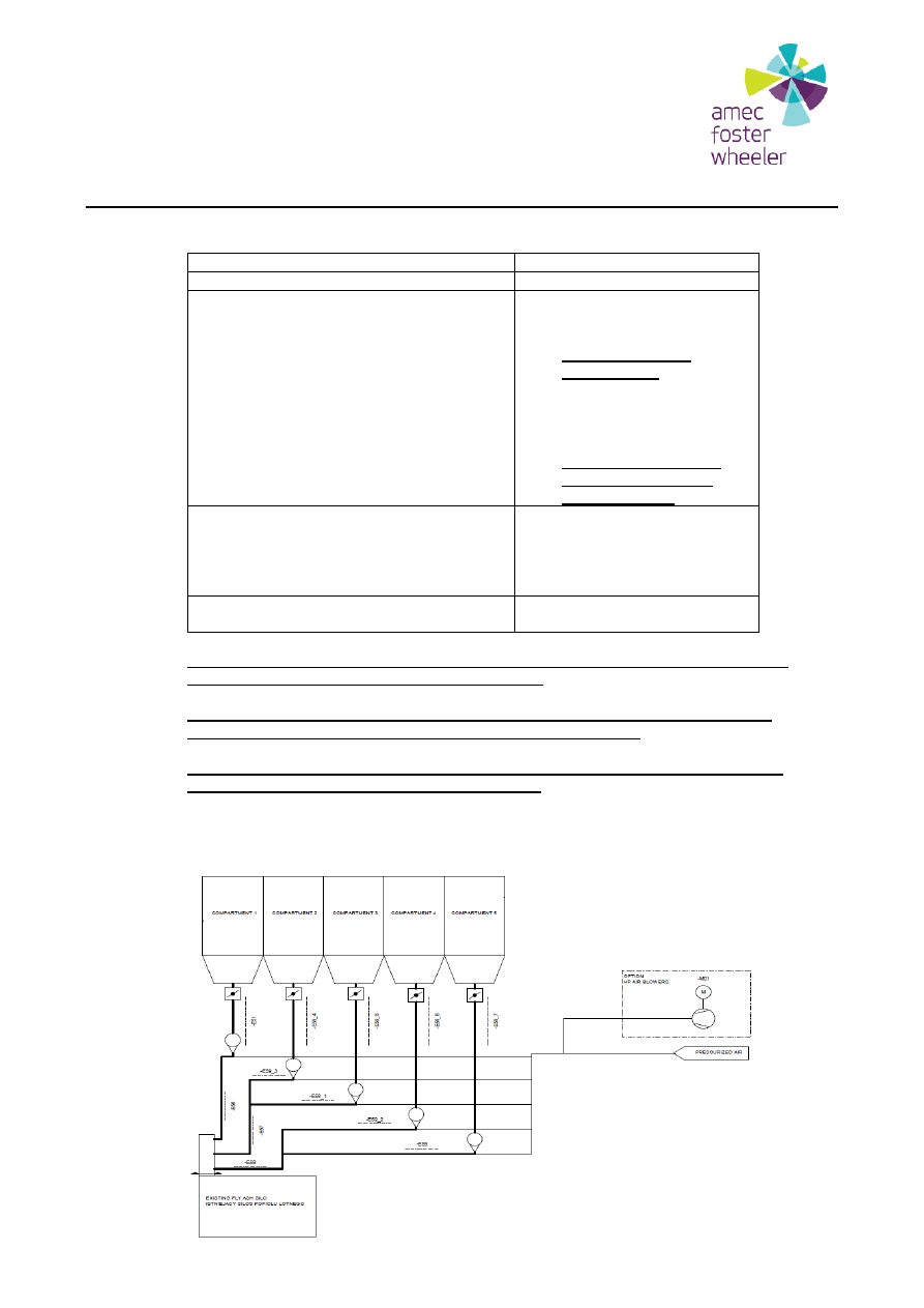
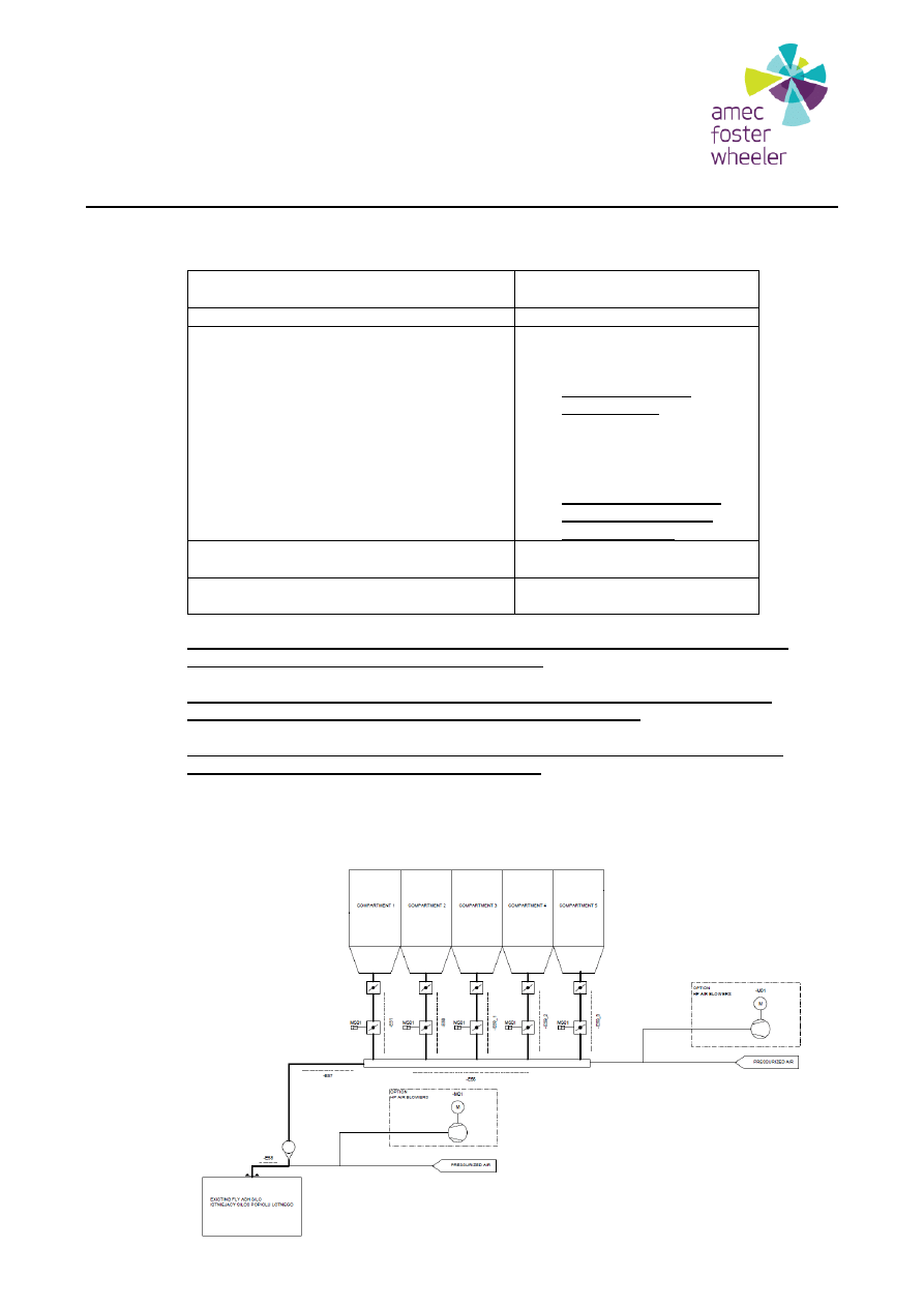
7.1 Fly ash handling system
– separate pneumatic transmitters
Number of pneumatic transmitters:
5 pcs (one for each hopper)
DIM mass flow rate from each hopper:
1 kg/s
Transport air:
Basic option:
-
compressed air
supplied by the Client;
please specify air
consumption
Additional option (separate
price):
-
transport air blowers
delivered by Supplier;
please specify proper
blowers and provide
prices for them
Distance between hoppers and silo
(transport distance):
Line 1: about 68 [m]
Line 2: about 64 [m]
Line 3: about 58 [m]
Line 4: about 55 [m]
Line 5: about 55 [m]
Silo Inlet Box:
Inlet Box design and
delivery required
All necessary equipment for this system should be specified and delivered by the
Supplier (in accordance to Supplier experience).
Please take also into consideration that whole system will be heated, thus each
device and each pipeline has to be prepared to apply heating.
In the Supplier scope is also the design and delivery of inlet box for existing silo.
Existing silo details
– see attachment number 5.
Flow diagram:
Engineering
23.11.2016
9 (17)
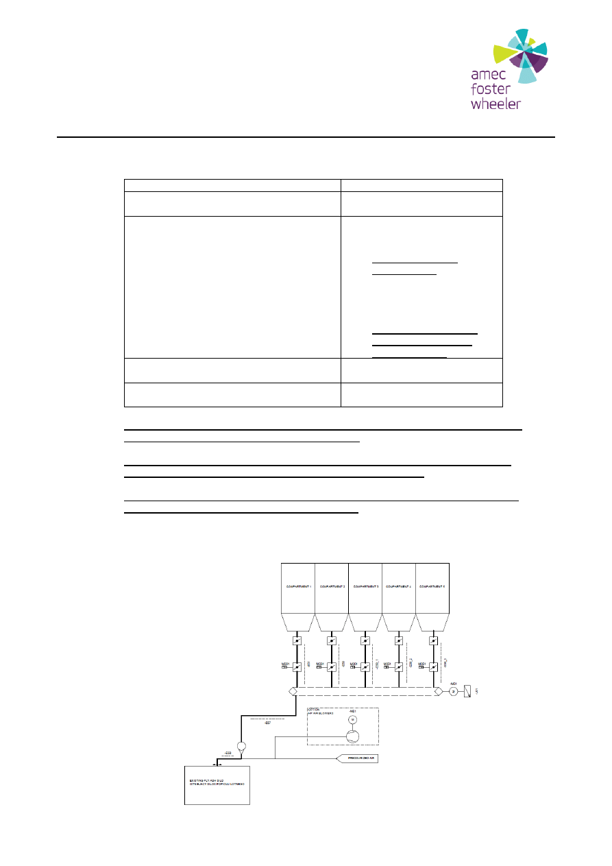
7.2 Fly ash handling system
– common cumulative collector
Number of common cumulative
collectors:
1 pc
DIM mass flow rate from collector to silo:
5 kg/s
Transport air:
Basic option:
-
compressed air
supplied by the Client;
please specify air
consumption
Additional option (separate
price):
-
transport air blowers
delivered by Supplier;
please specify proper
blowers and provide
prices for them
Distance between collector and silo
(transport distance):
About 59 [m]
Silo Inlet Box:
Inlet Box design and
delivery required
All necessary equipment for this system should be specified and delivered by the
Supplier (in accordance to Supplier experience).
Please take also into consideration that whole system will be heated, thus each
device and each pipeline has to be prepared to apply heating.
In the Supplier scope is also the design and delivery of inlet box for existing silo.
Existing silo details
– see attachment number 5.
Flow diagram:
Engineering
23.11.2016
10 (17)
7.3 Fly ash handling system
– chain conveyor
Number of chain conveyors:
1 pc
DIM mass flow rate from chain conveyor
to silo:
5 kg/s
Transport air:
Basic option:
-
compressed air
supplied by the Client;
please specify air
consumption
Additional option (separate
price):
-
transport air blowers
delivered by Supplier;
please specify proper
blowers and provide
prices for them
Distance between chain conveyor and
silo (transport distance):
About 59 [m]
Silo Inlet Box:
Inlet Box design and
delivery required
All necessary equipment for this system should be specified and delivered by the
Supplier (in accordance to Supplier experience).
Please take also into consideration that whole system will be heated, thus each
device and each pipeline has to be prepared to apply heating.
In the Supplier scope is also the design and delivery of inlet box for existing silo.
Existing silo details
– see attachment number 5.
Flow diagram:

Engineering
23.11.2016
11 (17)
7.4 Instrumentation and Control Equipment
– requirements
All the I&C equipment for Fly Ash Handling System should meet requirements specified in
Specification of Instrumentation and Control Equipment (attachment no. 6).
7.5 NTE Loads
Supplier should supply load diagram (Not To Exceed loads) for the equipment all together with
foundation layout. In the calculation should be included site conditions (point 4) from this
specification. All equipment installed outdoors should face the site conditions (point 4) from this
specification.
The bottom of the steel is 0,4m above the concrete slab.
All the instruments needed for proper operation of the Fly Ash Handling System are included
in scope of supply.
In case the above specified items which are not within your delivery scope please send
information indicating which are excluded.
7.6 Operation and Performance
The Fly Ash Handling System shall be designed for automatic operation without periodic
operator input. Operator input will be required for system startup or shoutdown or whenever
there is an alarm.
The Fly Ash Handling System shall be capable of operating for 24 hours per day and 7 days
per week on full automatic control.
8
SCOPE OF SUPPLY
Scope of supply shall include the design, manufacturing, factory testing, erection supervision
and instructions, training staff instructions, commissioning supervision and test run, O&M
instructions for the equipment delivered by Supplier.
Fly Ash Handling System shall be furnished with all the required equipment and accessories,
including, but not limited to, the following:
Complete Fly Ash Handling System with all necessary mechanical, electrical,
measurement systems, auxiliary equipment and pipelines
Equipment shall be furnished with all necessary supports
Anchor bolts
Support structure for pipelines
Design documentation for supplied equipment
Acoustic hood covering the entire unit made of galvanized steel sheet plate with oil
drip pan, forced ventilation by fan driven by independent shaft, acoustic hood for
indoor installation;
Lubrication units, if applicable;

Engineering
23.11.2016
12 (17)
Service kit with first fill of lubrication;
Logic Diagrams & Functional Descriptions;
Erection, Commissioning and Maintenance Instructions (English and Polish
language);
Any certificates required by EN/PED;
CE marking;
Declaration of conformity with Machinery Directive 2006/42/EC;
special tool requirements for installation start-up, operation, and maintenance (if
any);
wear and spare parts for start up and commissioning (separate price);
wear and spare parts, which are prerequisite for the availability guarantee during
the mechanical guarantee period of 2 years (separate price).
Requirements for option with transport blowers:
Transport air blower shall be furnished with all the required equipment and accessories,
including, but not limited to, the following:
Steel base plates for blower and motor;
Anchor bolts;
Anti-vibration pads;
Coupling;
Silencer on pressure side;
Flexible joints;
Safety valve;
Check valve (damper);
Maintenance/operational valve between lines;
Acoustic hood covering the entire unit made of galvanized steel sheet plate with oil
drip pan, forced ventilation by fan driven by independent shaft, acoustic hood for
indoor installation;
Lubrication units, if applicable;
Local pressure meters;
Vibration sensors for bearings and shaft;
Static and dynamic balancing for rotor;
Test runs at factory;
Service kit with first fill of lubrication;
Erection, commissioning and maintenance instructions (Polish & English
language);
Fire protection assumptions for design (if any);

Engineering
23.11.2016
13 (17)
Any certificates required by EN/PED;
CE marking;
Declaration of conformity with Machinery Directive 2006/42/EC;
special tool requirements for installation start-up, operation, and maintenance (if
any);
wear and spare parts for start up and commissioning (separate price);
wear and spare parts, which are prerequisite for the availability guarantee during
the mechanical guarantee period of 2 years (separate price).
In case the above-specified items are not within your delivery scope please send information
indicating which items are excluded.
9
DELIVERY LIMITS
Fly Ash Handling System:
Inlet:
outlets of fabric filter hoppers
Outlet:
outlet from inlet box at silo top
Electrification
equipment power supply terminals
I & C
signal terminals in field junction boxes
10
CONTENT OF THE OFFER
At least the following data should be given in the proposal:
-
Scope of supply;
-
Delivery limits;
-
Technical data and specifications of equipment;
-
Weights and dimensions of components;
-
Arrangement drawings;
-
Main flow diagram showing all equipment provided;
-
List and price of wear and spare parts for start up and commissioning (separate
price);
-
List and price of wear and spare parts, which are prerequisite for the availability
guarantee during the mechanical guarantee period of 2 years (separate price);
-
Option - erection supervision
–separate price;
-
Option - commissioning supervision
– separate price;
-
Media consumption list.
Engineering
23.11.2016
14 (17)
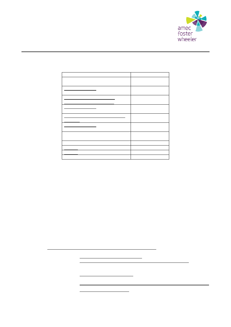
10.1 Pricing
The pricing for the system should be done according to the table below:
SYSTEM
PRICE (EURO)
1. Fly Ash Handling System
–
separate pneumatic transmitters
Option for item 1: Transport air
blowers
2. Fly Ash Handling System
–
common cumulative collector
Option for item 2: Transport air
blowers
3. Fly Ash Handling System
– chain
conveyor
Option for item 3: Transport air
blowers
Spare parts for Start Up and
Commissioning
Spare parts for 24 months (2 years)
Option: Erection supervision
Option: Commissioning supervision
TOTAL PRICE
11
PERFORMANCE AND OPERATION GUARANTEES
The Supplier is responsibility for design and construction of the supply. The Supplier shall guarantee
that the supply is according to the specification. All equipment must be new and not used before, free
of any error or defect of design or materials. All guarantees are absolute unless informed otherwise.
11.1 Time of Guarantee
The warranty period for the Equipment is 24 months starting from Taking Over protocol, 48
months for replaced or repaired parts. Replaced Equipment or parts thereof, shall be supplied
by Supplier at its cost, in line with the original delivery term. Dismantling, installation and on-site
repairs of defective parts shall be performed by Supplier at Supplier’s cost.
11.2 The following values should be guaranteed:
Fly Ash Handling System with separate pneumatic transmitters:
1) Each pneumatic transmitter capacity: 1 kg/s
2) Power consumption for Guarantee Point (see item 6.2 and 6.3)
– XX kW –
TBD and guaranteed by Supplier
– each pneumatic transmitter capacity in
GP: 0.39 kg/s
3) Maximum Power Consumption: XX kW
– TBD and guaranteed by Supplier -
each pneumatic transmitter capacity: 1 kg/s
4) Air consumption (case 1: compressed air supplied by Customer
–
parameters: see item 6.4) - XX m
3
(n)/h (TBD by Supplier; amount
–
guaranteed value)

Engineering
23.11.2016
15 (17)
5) Air consumption (case 2: transport air blowers) - XX m
3
(n)/h (TBD by
Supplier; amount
– guaranteed value, parameters (dry/wet, temperature of
pressure dew point of air))
Fly Ash Handling System with common cumulative collector:
1) Mass flow rate from collector to silo: 5 kg/s
2) Power consumption for Guarantee Point (see item 6.2 and 6.3)
– XX kW –
TBD and guaranteed by Supplier
– mass flow rate from collector to silo in
GP: 1.95 kg/s
3) Maximum Power Consumption: XX kW
– TBD and guaranteed by Supplier
– mass flow rate from collector to silo: 5 kg/s
4) Air consumption (case 1: compressed air supplied by Customer
–
parameters: see item 6.4) - XX m
3
(n)/h (TBD by Supplier; amount
–
guaranteed value)
5) Air consumption (case 2: transport air blowers) - XX m
3
(n)/h (TBD by
Supplier; amount
– guaranteed value, parameters (dry/wet, temperature of
pressure dew point of air))
Fly Ash Handling System with chain conveyor:
1) Mass flow rate from chain conveyor to silo: 5 kg/s
2) Power consumption for Guarantee Point (see item 6.2 and 6.3)
– XX kW –
TBD and guaranteed by Supplier
– mass flow rate from chain conveyor to
silo in GP: 1.95 kg/s
3) Maximum Power Consumption: XX kW
– TBD and guaranteed by Supplier
– mass flow rate from chain conveyor to silo: 5 kg/s
4) Air consumption (case 1: compressed air supplied by Customer
–
parameters: see item 6.4) - XX m
3
(n)/h (TBD by Supplier; amount
–
guaranteed value)
5) Air consumption (case 2: transport air blowers) - XX m
3
(n)/h (TBD by
Supplier; amount
– guaranteed value, parameters (dry/wet, temperature of
pressure dew point of air))
11.3 Vibration
Blower power
≤ 15 kW
Blower units shall be able to achieve the vibration criteria defined in the following standards:
PN ISO10816-1: 1998, PN ISO10816-1: 2009 and ISO 7919-3:2009.
Blower power > 15 kW
Blower units shall be able to achieve the vibration criteria defined in the following standards:
PN ISO10816-3: 2009 and ISO 7919-3:2009.
11.4 Noise
The sound pressure level (L
PA
) from an individual apparatus in the scope of supply shall not
exceed 85 dB(A). The sound pressure level (L
PA
) is defined in accordance with EN ISO
3746:2011 and measured at 1 m distance from the individual apparatus.
Engineering
23.11.2016
16 (17)
11.5 Avaliability
The guaranteed average availability (A
VB
) shall not be less than 99,70% per year during the
Availability Period (24 months).
The guaranteed annual availability shall be the average of yearly availabilities, which shall be
calculated in accordance with the equation shown below. First year starts from the date of
Taking Over. The annual average availability shall be calculated after the Mechanical
Guarantee period has ended.
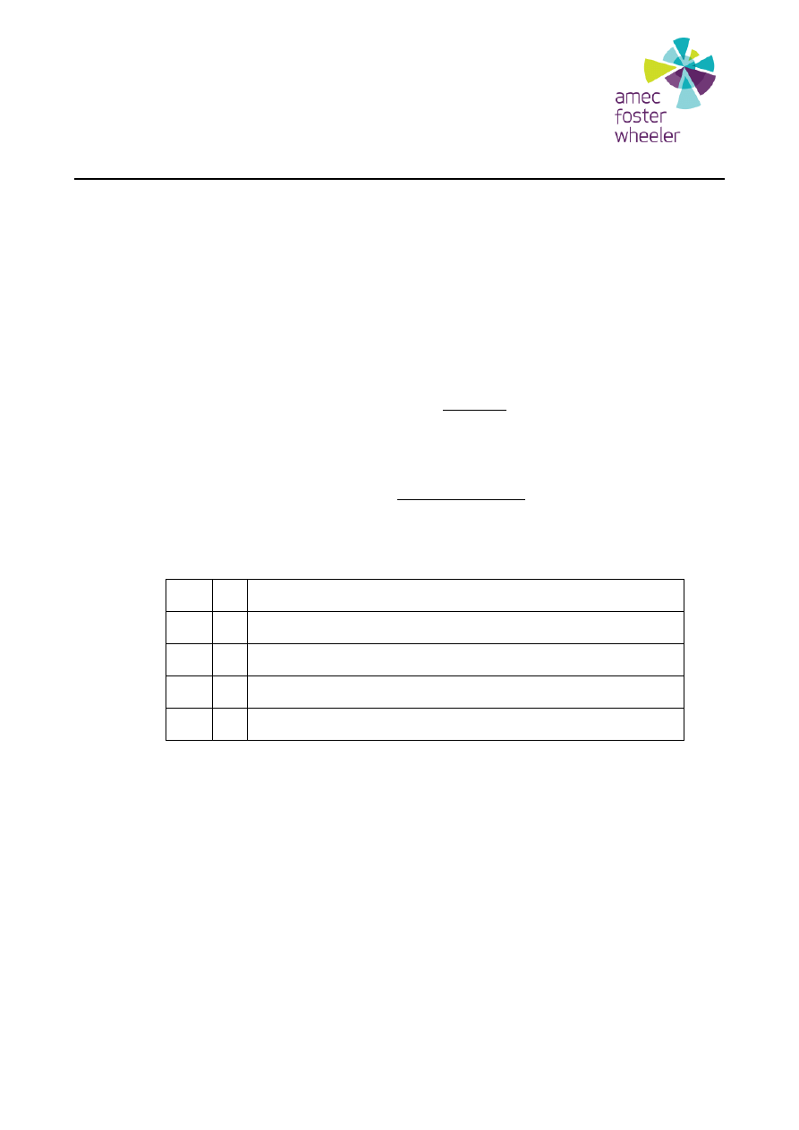
The guaranteed average annual availability shall be calculated on percentage basis with the
following equation:
2
(%)
2
1
V
V
V
A
A
A
B
The guaranteed annual availability shall be calculated on percentage basis with the following
equation:
100
8760
8760
(%)
exp
2
,
1
main
un
main
V
T
T
T
A
Where:
8760
=
Number of hours per year
1)
A
V1
=
Availability during the first year of the Mechanical Guarantee Period
A
V2
=
Availability during the second year of the Mechanical Guarantee Period
T
main
=
Total time of planned outages during the year
T
unexp
=
Total time of unplanned outages during the year
2)
The Works shall be considered to be in operation:
1. If the Works can be operated within its specified operating range without any restrictions to
load caused by any equipment or system forming a part of the Works and providing that the
environmental requirements are met.
2. If the Works would meet the conditions set in item 1 above, but are actually not in operation
due to reasons not attributable to the Contractor, such as:
No outside electricity to start-up the Works;
No personnel available to operate the Works (such as illness, operator not available);
Governmental decision or declaration not to operate or start the Works ;
Damages due to operator fault (e.g., faulty operation and maintenance, combustion of
fuel other than specified in the Contract);
Lack of reagents, consumables or no reagents. consumables available at all;
Plant outage caused by failure in parts not included in the Works.

Engineering
23.11.2016
17 (17)
11.6 Documentation
Final documents and drawings shall be delivered in size are in accordance with ISO A-series.
Documentation requirements will be given after choosing Supplier of Fly Ash Handling System.
The measures of all documents shall be given in SI units.
12 ENCLOSURES
1. Fly Ash Handling System with separate pneumatic transmitters
– flow diagram -
FWH++++++-MFB0001.pdf
2. Fly Ash Handling System with common cumulative collector
– flow diagram - FWH++++++-
MFB0002.pdf
3. Fly Ash Handling System with chain conveyor
– flow diagram - FWH++++++-MFB0003.pdf
4. Overall layout of FGT
– O11059_Revf.pdf
5. Drawing of existing silo
– 221001.pdf
6. Specification of instrumentation and control equipment.pdf
Wyszukiwarka
Podobne podstrony:
SYSTEMY1, technik informatyk, soisk utk
Eksploatacja systemów technicznych ćwiczenie 1
Systemy techniczne instalacji sanitarnych
Opis techniczny projektowanego systemu zaopatrzenia w wod(1), Uczelniane, Systemy techniczne instala
Eksploatacja systemów technicznych-ćwiczenie 3
Eksploatacja systemów technicznych ćwiczenie 3
EKSPLOATACJA SYSTEMÓW TECHNICZNYCH ], sep, Eksploatacja Maszyn
projektowanie systemów technicznych arkusz dla prowadzącego
Eksploatacja systemów technicznych ćwiczenie 5
4 Systemy i techniki pomiarowe w monitoringu środowiska
Eksploatacja systemów technicznych ćwiczenie 8
Eksploatacja systemów technicznych ćwiczenie 2
Eksploatacja systemów technicznych ćwiczenie 6
Eksploatacja systemów technicznych ćwiczenie 7
wybrane systemy i techniki pomiarowe
Systemy techniczne
SYSTEMY1, technik informatyk, soisk utk
Eksploatacja systemów technicznych ćwiczenie 1
więcej podobnych podstron