T.O. 33D9-17-89-1
TECHNICAL MANUAL
INTERMEDIATE MAINTENANCE INSTRUCTIONS
GUIDANCE SECTION
COOLER TEST REPAIR SET
PART NO. 25-33383-173
A/E47T-23
BOEING
F42600-82-G-7501
F42600-90-D-0457
F42610-98-C-0001
DISCLOSURE NOTICE:
This information is furnished upon the condition that it will not be released to another nation without the specific
authority of the Department of the Air Force of the United States; it will be used for military purposes only; individual or corporate rights originating
in the information, whether patented or not, will be respected; the recipient will report promptly to the United States any known or suspected
compromise; and the information will be provided substantially the same degree of security afforded it by the Department of Defense of the
United States. Also, regardless of any other markings on the document, it will not be downgraded or declassified without written approval of the
originating United States agency.
DISTRIBUTION STATEMENT:
Distribution authorized to US Government Agencies and their contractors for administrative and operational use
as of 26 January 1984. Other requests for this document shall be referred to 526 ICBMSG ⁄ ENV, Hill AFB, UT 84056-5816.
WARNING:
This document contains technical data whose export is restricted by the Arms Export Control Act (Title 22, U.S.C., Sec 2751, et
seq) or the Export Administration Act of 1979, as amended, (Title 50, U.S.C. App. 2401, et seq). Violations of these export laws are subject to
severe criminal penalties. Disseminate in accordance with the provisions of AFI 61-204.
HANDLING AND DESTRUCTION NOTICE:
Comply with distribution statement and destroy by any method that will prevent disclosure of the
contents or reconstruction of the document.
Published under authority of the Secretary of the Air Force
22 FEBRUARY 2005
CHANGE
3
2 APRIL 2008
Basic and all changes have been merged to make this a complete publication.

Dates of issue for original and changed pages are:
Original . . . . . . . . . 0 . . . . . 22 February 2005
Change . . . . . . . . . 2 . . . . . . . . 5 July 2006
Change . . . . . . . . . 1 . . . . . . . 29 June 2006
Change . . . . . . . . . 3 . . . . . . . 2 April 2008
TOTAL NUMBER OF PAGES IN THIS PUBLICATION IS 96 CONSISTING OF THE FOLLOWING:
Page
*Change
Page
*Change
Page
*Change
No.
No.
No.
No.
No.
No.
Title . . . . . . . . . . . . . . . . . . . .
3
A . . . . . . . . . . . . . . . . . . . . . .
3
i . . . . . . . . . . . . . . . . . . . . . . .
2
ii - viii . . . . . . . . . . . . . . . . . .
0
1-1 - 1-3 . . . . . . . . . . . . . . . . .
0
1-4 Blank . . . . . . . . . . . . . . . . .
0
2-1 - 2-3 . . . . . . . . . . . . . . . . .
0
2-4 Blank . . . . . . . . . . . . . . . . .
0
3-1 - 3-4 . . . . . . . . . . . . . . . . .
0
4-1 - 4-14 . . . . . . . . . . . . . . . .
0
5-1 - 5-7 . . . . . . . . . . . . . . . . .
0
5-8 . . . . . . . . . . . . . . . . . . . . .
1
5-8.1 Added . . . . . . . . . . . . . . .
1
5-8.2 Blank . . . . . . . . . . . . . . .
1
5-9 - 5-11 . . . . . . . . . . . . . . . .
0
5-12 . . . . . . . . . . . . . . . . . . . .
3
5-12.1 Added . . . . . . . . . . . . . .
3
5-12.2 Blank . . . . . . . . . . . . . . .
3
5-13 - 5-14 . . . . . . . . . . . . . . .
0
5-15 . . . . . . . . . . . . . . . . . . . .
3
5-16 . . . . . . . . . . . . . . . . . . . .
0
5-17 . . . . . . . . . . . . . . . . . . . .
1
5-18 - 5-21 . . . . . . . . . . . . . . .
0
5-22 . . . . . . . . . . . . . . . . . . . .
1
5-23 - 5-40 . . . . . . . . . . . . . . .
0
5-41 . . . . . . . . . . . . . . . . . . . .
2
5-42 - 5-43 . . . . . . . . . . . . . . .
0
5-44 Blank . . . . . . . . . . . . . . . .
0
FP-1 . . . . . . . . . . . . . . . . . . . .
0
FP-2 Blank . . . . . . . . . . . . . . . .
0
FP-3 . . . . . . . . . . . . . . . . . . . .
0
FP-4 Blank . . . . . . . . . . . . . . . .
0
FP-5 . . . . . . . . . . . . . . . . . . . .
0
FP-6 Blank . . . . . . . . . . . . . . . .
0
FP-7 . . . . . . . . . . . . . . . . . . . .
0
FP-8 Blank . . . . . . . . . . . . . . . .
0
FP-9 . . . . . . . . . . . . . . . . . . . .
0
FP-10 Blank . . . . . . . . . . . . . . .
0
FP-11 . . . . . . . . . . . . . . . . . . .
0
FP-12 Blank . . . . . . . . . . . . . . .
0
T.O. 33D9-17-89-1
LIST OF EFFECTIVE PAGES
INSERT LATEST CHANGED PAGES. DESTROY SUPERSEDED PAGES.
NOTE
The portion of the text affected by the changes is indicated by a vertical line in
the outer margin of the page. Changes to illustrations are indicated by shaded
or screened areas, or by miniature pointing hands.
* Zero in this column indicates an original page.
USAF
A
Change 3

INTRODUCTION AND GENERAL INFORMATION
. . . . . . . . . . . . . . . . . . . . . . . . . . . . . . . . . . . . . . . 1-1
SPECIAL TOOLS AND TEST EQUIPMENT
. . . . . . . . . . . . . . . . . . . . . . . . . . . . . . . . . . . . . . . . . . . . . 2-1
Shipping and Storage Requirements
. . . . . . . . . . . . . . . . . . . . . . . . . . . . . . . . . . . . . . . . . . . . 3-1
Photoelectric Controller Installation
. . . . . . . . . . . . . . . . . . . . . . . . . . . . . . . . . . . . . . . . . . . . 3-3
. . . . . . . . . . . . . . . . . . . . . . . . . . . . . . . . . . . . . . . . . . . . . . . . 4-2
. . . . . . . . . . . . . . . . . . . . . . . . . . . . . . . . . . . . . . . . . . . . . . . . .
T.O. 33D9-17-89-1
TABLE OF CONTENTS
Chapter
Page
Change 2
i

Measuring Tube Heater Replacement
. . . . . . . . . . . . . . . . . . . . . . . . . . . . . . . . . . . . . . . . . .
T.O. 33D9-17-89-1
TABLE OF CONTENTS - Continued
Chapter
Page
ii

T.O. 33D9-17-89-1
LIST OF ILLUSTRATIONS
Number
Title
Page
iii

Special Tools and Test Equipment
. . . . . . . . . . . . . . . . . . . . . . . . . . . . . . . . . . . . . . . . . . . . . . . . 2-2
Preoperational Checkout - Left Panel
. . . . . . . . . . . . . . . . . . . . . . . . . . . . . . . . . . . . . . . . . . . . .
Preoperational Checkout - Right Panel
. . . . . . . . . . . . . . . . . . . . . . . . . . . . . . . . . . . . . . . . . . . .
Control Valve Driver Circuit Checkout
. . . . . . . . . . . . . . . . . . . . . . . . . . . . . . . . . . . . . . . . . . . .
Coolant System Troubleshooting
. . . . . . . . . . . . . . . . . . . . . . . . . . . . . . . . . . . . . . . . . . . . . . . .
T.O. 33D9-17-89-1
LIST OF TABLES
Number
Title
Page
iv
SAFETY SUMMARY
GENERAL SAFETY INSTRUCTIONS.
This manual describes physical and chemical processes, which could cause injury or death to personnel, or damage to
equipment if not properly followed. This safety summary includes general safety precautions and instructions that must be
understood and applied during operation and maintenance to ensure personnel safety and protection of equipment. Prior to
performing any task, the WARNINGs, CAUTIONs, and NOTEs included in that task shall be reviewed and understood.
WARNINGS, CAUTIONS, AND NOTES.
WARNINGs and CAUTIONs are used in the manual to highlight operating or maintenance procedures, practices, conditions,
or statements, which are considered essential to protection of personnel (WARNING) or equipment (CAUTION). WARNINGs
and CAUTIONs precede the step or procedures to which they apply. WARNINGs and CAUTIONs consist of four parts:
Heading (WARNING and CAUTION), a statement of the hazard, minimum precautions, and possible result if disregarded.
NOTEs are used in this manual to highlight operating or maintenance procedures, practices, conditions, or statements that are
not essential to protection of personnel or equipment. NOTEs may precede or follow the step or procedure, depending upon
the information to be highlighted. The headings used and their definitions are as follows:
Highlights an essential operating or maintenance procedure, practice, condition, statement,
etc., which, if not strictly observed, could result in injury to, or death of, personnel or long
term health hazards.
Highlights an essential operating or maintenance procedure, practice, condition, statement,
etc., which, if not strictly observed, could result in damage to, or destruction of, equipment
or loss of mission effectiveness.
NOTE
Highlights an essential operating or maintenance procedure, practice, condition or statement.
HAZARDOUS MATERIALS WARNINGS.
Hazardous material WARNINGs in this manual are used to warn personnel of Personal Protective Equipment (PPE),
ventilation, fire and other hazards. If the PPE for the hazardous material has changed (ref. product MSDS) consult with Base
Bioenvironmental Engineering to determine if the current T.O. PPE is adequate. If the PPE is not adequate, notify 20AF/LGM.
Hazardous Materials Description.
The following hazardous materials are used in this manual:
HFC (R134A) is an asphyxiant and contains chlorofluorocarbon (CFC). Use in a well-ventilated area. Respiratory protection
is not normally required in well-ventilated area, but dense vapors in confined spaces displaces breathing air causing
asphyxiation. Protective clothing should minimize exposed skin. Wear cloth-lined rubber gloves and goggles plus faceshield.
Liquid coming in contact with the skin could cause frostbite. Treat frostbite by applying warm water to the affected area.
Dry lubricant is toxic and hazardous. Wear neoprene or mylar gloves and chemical goggles. Use in a well-ventilated area.
High vacuum sealant is toxic and hazardous. Wear impervious gloves and safety glasses. Use in a well-ventilated area.
T.O. 33D9-17-89-1
v

Refrigerant compressor oil is a skin and eye irritant. Wear rubber or nitrile gloves and chemical workers goggles to prevent
eye/hand contact. Use in a well-ventilated area. If contact with skin occurs, wash affected area with soap and water. If contact
with eyes occurs, do not rub. Flush eyes with water for at least 15 minutes while holding upper and lower eyelids open to
ensure complete cleansing. Wash hands with soap and water after handling oil. Keep away from excessive heat, sparks, and
open flames.
Armstrong 520 adhesive is flammable and toxic. Use in a well-ventilated area. Excessive skin contact could cause drying and
cracking of skin and dermatitis. Wear chemical-resistant gloves and chemical workers goggles/faceshield to prevent eye/hand
contact. Wash hands with soap and water after handling. Keep away from excessive heat, sparks and open flames.
Sodium chromate is caustic, corrosive, and toxic. Respiratory protection is not required where adequate ventilation exists.
Wear neoprene gloves and safety goggles/faceshield, cotton coveralls with sleeves extended into gloves, and an apron shall
be worn over the coveralls. Check to see that all parts of the body are covered. Use in a well-ventilated area. If dusty situations
prevail, work in ventilation hood or wear NIOSH-approved dust respirator or mask. If inhaled, remove to fresh air
immediately. If contact with skin occurs, wash affected area with water immediately. If contact with eyes occurs, do not rub.
Flush eyes with water for at least 15 minutes while holding upper and lower eyelids open to ensure complete cleansing; then
get medical aid immediately. Wash after handling and before eating, drinking, or smoking.
A health hazard exists to personnel whenever mercury is spilled and comes in contact with the body. Should a mercury spill
occur, the following health safety actions are required: wear rubber gloves during cleanup, package and dispose through local
DPDO office, and contact Bioenvironmental Engineering Organization.
Ultrasonic cleaning detergent is hazardous. Detergent is a skin, eye, and inhalation irritant. Use in a well-ventilated area. Wear
rubber gloves and chemical splash goggles. If contact with eyes occurs, do not rub. Flush eyes with water for at least 15
minutes while holding upper and lower eyelids open to ensure complete cleansing; if irritation persists, consult a physician.
If contact with skin occurs, flush area with water for 15 minutes. Wash hands thoroughly after handling.
SAFETY PRECAUTIONS.
The following safety precautions shall be observed while performing procedures in this manual. (WARNINGs, CAUTIONs,
and/or NOTEs will be repeated within this manual.)
Electrical Safety Requirements.
Rubber goods designed for protection of the technician (electrical rubber gloves with leather protective shells and rubber mats)
shall be used when working on energized electrical circuits of 50 volts or more. Electrical rubber gloves with leather protective
shells, rubber mats, and rubber blankets shall be used while testing energized electrical circuits of 600 volts or more. When
working adjacent to electrically energized circuits in excess of 600 volts, electrical rubber blankets shall be used to cover
energized equipment. Testing of energized electrical circuits shall only be done while standing on and in contact with dry
surfaces. Normal troubleshooting activity involving the operation of switches, the insertion and/or removal of fuses, or testing
of exposed conductors on circuits below 600 volts do not require rubber protective goods. When working adjacent to energized
electrical circuits, the technician shall wear applicable safety equipment or use a rubber blanket when deemed necessary.
Detailed information on rubber matting, gloves, and blankets can be found in AFOSH Standard 91-501.
Two people (buddy/buddy) within easy access of each other are required during testing, troubleshooting, or performing
maintenance on energized equipment.
Lockout or tagout devices shall be attached when circuit breakers or switches are opened to perform maintenance.
After removing power from a component, verify no voltage is present prior to performing maintenance.
Actual fuse amperage ratings shall be verified prior to installation/reinstallation.
T.O. 33D9-17-89-1
vi

Probing Requirements.
Weapon System Specification requirements prohibit direct probing of “in-line launch critical circuits” by organizational level
maintenance. The use of approved T.O. procedures to include breakout connector adapters and approved testing equipment
must be strictly followed when fault isolating “in-line launch critical circuits”. Organizational maintenance may use direct
probing techniques on nonlaunch critical circuits when approved by specific T.O. procedure. Technical Engineering may use
direct probing techniques on nonlaunch critical circuits to perform fault isolation using schematics and normal testing
techniques with approved testing equipment (appropriate T.O. and/or T.O. 21M-LGM30F-12 listed equipment). Technical
Engineering will contact OO-ALC/LMEI (SELECT) if there is a question on whether or not a circuit is “in-line launch
critical”.
Manual Lift Requirements.
Maintenance equipment, tools, and replacement components could be awkward and heavy to handle. Consider team lifting
when items are known to weigh more than 25 pounds. All pertinent lifting factors should be considered when determining
lifting requirements (i.e. individual’s strength, distance item is carried, and size and weight of the object). Any object too
difficult to be lifted/carried by one person should be lifted/carried by two or more personnel or use a mechanical lift. A NOTE
identifying the weight of the item to be lifted shall be placed in the procedure just prior to lifting heavy (approximately 60
pounds or more) and/or awkward items.
Summary of Warnings.
120-Vac power is present inside cabinet when power cables are connected. Serious shock hazard exists when panels are off.
Pressure is present in the hose. Faceshield and rubber gloves must be used to prevent personnel injury.
120/208 volts of power is present inside test bench. Serious shock hazard exists when panels are removed.
Do not exceed 250-psig pressure when testing PS-1 and TS-1 and make no adjustments except as specified. PS-1 and TS-1
are safety devices to protect equipment and personnel.
Summary of Cautions.
When closing test bench manual shutoff valves, the use of excessive force can damage valve seats.
S3 must be set correctly before S2 is operated to prevent damage to control valve motor.
Facility ground wire, electrical cables, and air shall be connected before operating.
Do not leave MEASURING TUBE HEATER switch on when measuring tube is empty.
Initial coolant flow shall not exceed 1.5 pounds per minute until air is forced out of coolant lines. Excessive air flow rate can
damage test bench.
COMPRESSOR AIR RETURN FLOW meter shall not be allowed to exceed 2.5 cfm. Failure to comply could result in damage
to flow transducer MT4.
Use two wrenches when loosening or tightening fittings to avoid stressing plumbing system.
Failure to set REFRIGERANT MEASURING TUBE HEATER switch to OFF when measuring tube is not in filled condition
will overheat and damage measuring tube assembly.
CONTROL VALVE switch S3 must be set correctly before connecting control valve and operating OPEN/CLOSE switch S2.
GENERAL SAFETY PRECAUTIONS.
The following general safety precautions shall be complied with throughout this manual. (These precautions will NOT be
repeated within the manual.)
Soldering iron is hot and solder could pop/splash. Avoid contact with tip and wear approved eye protection.
Blow drying items may be hazardous to eyes and skin. Wear goggles and ensure pressure is less than 30 psi.
T.O. 33D9-17-89-1
vii

Cleaning with compressed air can create an eye and/or skin hazard. Wear goggles; ensure air is regulated to less than 30 psi
and do not direct the air against skin.
Do not wear metal-type jewelry when working around electronic/electrical equipment.
Shop technicians may work on low voltage circuits (electrical systems of less than 50 volts excluding the MAF and LF
batteries and other high amperage systems), while energized for the purpose of testing, calibrating, troubleshooting, minor
repairs, and replacement of fuses/circuit breakers. Lockout/tagout power sources whenever possible. Comply with applicable
AFOSH requirements.
Sodium chromate solution is a hazardous waste. Contact Bioenvironmental Engineering Office for disposal procedures.
Minuteman Base Coding.
Code symbols are used in this manual to show which information is applicable to a particular base or group of bases. When
code symbols appear in paragraph titles, illustration titles, illustration or procedural steps, the information applies only to the
base(s) represented by the code symbol. Where no coding appears, the information is applicable to all base(s) covered by this
manual. The following code symbols are used:
[1] Wing 1, Squadrons 1 through 3.
[1X] Wing 1, Squadron 4.
< End of coded information where not otherwise obvious
List of Related Publications
Number
Title
T.O. 00-20-3
Maintenance Processing of Reparable Property and Repair
Cycle Asset Control Systems
T.O. 21M-LGM30F-01
List of Applicable Publications, LGM30 Weapon System
T.O. 21M-LGM30F-4-(Series)
LGM30F Weapon System Illustrated Parts Breakdown
T.O. 21M-LGM30F-6
Scheduled Inspection and Maintenance Requirements
T.O. 21M-LGM30F-12
Special Maintenance Safety and Electromagnetic
Interference Provisions Safety Manual
T.O. 21M-LGM30F-101
Corrosion Control and Treatment
T.O. 21M-LGM30G-2-31
Weapon System Hardness Preservation and Installation
Hardware
T.O. 33D9-17-89-1
viii
CHAPTER 1
INTRODUCTION AND GENERAL INFORMATION
1.1
INTRODUCTION.
This manual includes instructions for operation and intermediate level maintenance of the guidance section cooler test repair
set A/E47T-23, Part No. 25-33383-173, hereinafter referred to as the test bench. See Figure 1-1. Operation instructions,
Chapter 4, briefly describes theory of operation and includes procedures for startup, checkout, and shutdown; however,
detailed use of the test bench is described in T.O. 35E9-35-22, Guidance Section Liquid Cooler Maintenance. Maintenance
instructions, Chapter 5, consists of test bench checkout, troubleshooting, and repair procedures. Special tools and test
equipment required for maintenance of the test bench, Chapter 2, are identified by nomenclature, number, and application.
Chapter 3 describes preparation of the test bench for use and preparation for shipment.
1.2
GENERAL INFORMATION.
At all Minuteman wings, the test bench is used at the MSB as the checkout and repair facility for the guidance control section
liquid cooler. The following parts can be individually connected to and operated on the test bench:
a.
Coolant Chiller Unit, FRK-2/F37U-9
b.
Compressor, part of FRK-2/F37U-9
c.
Coolant Pump, PMK-48/F37U-9
d.
Control Valve Assembly, VAK-31/F37U-9 (400 Hz)
e.
Control Valve Assembly, VAK-36/F37U-22 (DC)
When closing test bench manual shutoff valves, the use of excessive force can damage valve
seats.
NOTE
Before removing/replacing components, check for faulty wiring, control air leaks, and other
abnormal conditions using standard maintenance practice.
1.2.1
Test Bench.
The test bench features do not include provisions for maintaining the electronic control amplifier,
which is tested and repaired according to T.O. 35E9-35-22. The test bench contains a supply of coolant, and it connects to
compressed air which is used for purging coolant from components after test. A vacuum pump and controls are built into the
test bench for evacuation of the chiller. A refrigerant supply cylinder with heater is contained in the rear of the test bench.
Driving signals for the control valve assemblies’ motors are electronically generated within the test bench.
T.O. 33D9-17-89-1
1-1
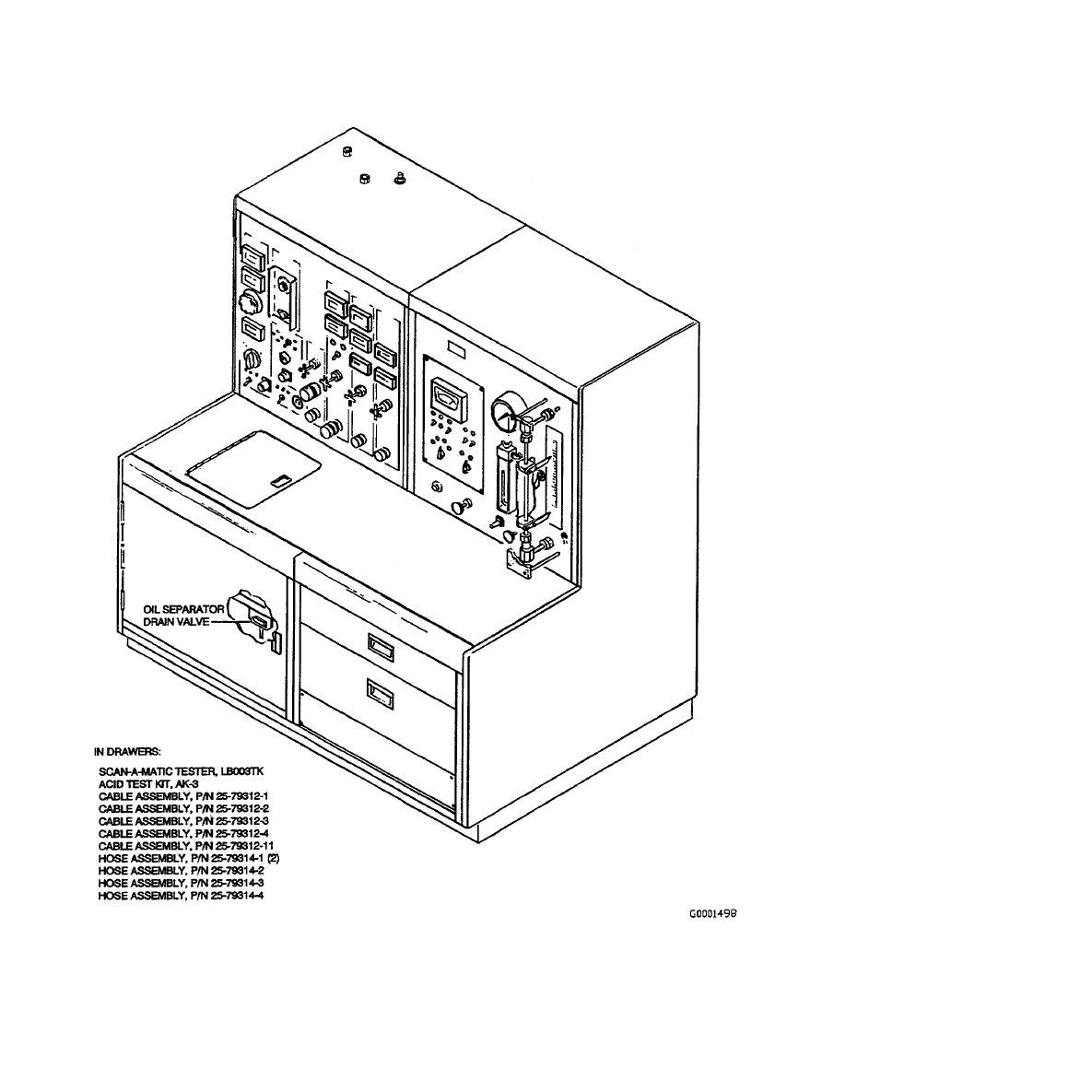
Figure 1-1. Guidance Section Cooler Test Repair Set A/E47T-23
T.O. 33D9-17-89-1
1-2
Table 1-1. Table of Leading Particulars
Guidance Section Cooler Test Repair Set
Width
66.125 inches
Height
69.875 inches
Depth
44.0 inches
Weight
1000 pounds approximately
Input electrical service
a. 208/120 Vac 60 Hz 3Ø 20 amps
b. 208/120 Vac 400 Hz 3Ø 10 amps
Input compressed air
100 psi
Table 1-2. List of Consumable Materials
Item
Identification
Application
Refrigerant
HFC134a
To refill 125-pound test bench cylinder.
High vacuum sealant
3M Weatherban 606-NF White
Acrylic Sealant or equivalent
To seal refrigerant and vacuum connections.
Pipe joint sealing tape
3M Teflon Tape Type B or equiva-
lent
For assembly of pipe thread tubing fittings.
Dry lubricant
Miller Stephenson MS122N/CO2,
NSN 9150-01-390-1408,
or MS-122B (replacement)
For assembly of straight thread tubing fittings.
Adhesive
Armstrong type 520 or equivalent
For installation of refrigerant measuring tube heating
elements.
Vacuum pump oil
Super X/Flushing High Vacuum
Pump Oil 5000 or equivalent
For refilling vacuum pump.
Ultrasonic cleaning
concentrate detergent
MICRO-10 7930-01-300-3536 or
equivalent
Used in ultrasonic cleaner.
T.O. 33D9-17-89-1
1-3/(1-4 blank)


CHAPTER 2
SPECIAL TOOLS AND TEST EQUIPMENT
2.1
GENERAL INFORMATION.
This chapter lists the test equipment and special tools for performing checkout, troubleshooting, adjustment, and repair
procedures of the cooler test repair set.
2.2
ALTERNATE EQUIPMENT.
If the primary electrically-powered tool, test equipment, or item is not available, an approved alternate may be used. Alternate
Air Force standard test equipment and tools may be used as follows:
NOTE
Only government furnished equipment used for official government business will be
evaluated for approval as exempt power devices (refer to T.O. 21M-LGM30F-12).
a.
Except when specifically designed test equipment is called for or when nuclear certified test equipment is required
per the Master Nuclear Certification List (MNCL) and alternate items are not listed therein, or when the table for
support equipment does not authorize the use of an alternate or equivalent item/substitute.
NOTE
Electromagnetic Interference (EMI) and Electromagnetic Compatibility (EMC) may have
adverse effects on weapons system equipment or ordnance items. Weapon System Specifi-
cations and MIL-STD-461 requirements must be complied with during the selection process
for identifying alternate electrically-powered tools, items, and test equipment.
b.
Any substitute identified by the Test Measurement and Diagnostic Equipment (TMDE) branch, Technical Engi-
neering (TE), or items identified by the USAF Interchangeability and Substitution (I&S) group stock list shall be
forwarded to 20AF/LGM for approval. 20AF shall forward the request to OO-ALC/LME for final evaluation and
approval.
c.
The same authority may be exercised by TE for all other equipment and special tools. Extreme care shall be used
in selection and use of substitute (alternate) equipment to ensure weapon system or equipment degradation does
not result from the use of the substitute.
2.3
TOOLS AND TEST EQUIPMENT.
The tools and test equipment used in this technical manual are listed in Table 2-1. Common hand tools required for the job
are not listed.
T.O. 33D9-17-89-1
2-1
Table 2-1. Special Tools and Test Equipment
Nomenclature
Designation
Purpose
Multimeter, Digital
6625-00-005-1233 or equivalent
Voltage, resistance, and continuity measuring.
Oscilloscope with
HP181A dual channel
amplifier
6625-00-477-3616 or equivalent
Modulating control valve motor driving waveform
measuring.
Ammeter, clamp-on type
6625-00-649-0411 or equivalent
Checkout of 400 Hz POWER AMPERAGE meter.
Frequency Counter,
SAMME120
6625-00-165-2129 or equivalent
Checkout of 400 Hz POWER FREQUENCY meter.
Nitrogen Bottle, charged
with 250 psig or greater
dry nitrogen
--
Various pressure and flow tests.
Regulator
Assembly-Compressed
Gas
4820-01-018-9604 or equivalent
Nitrogen pressure control.
Nitrogen Adapter
Assembly
Locally manufactured See Figure 2-1
Connects regulator to test bench.
Test Stand used with
A/E47T-23
Part No. 25-79824-1
Calibration standard for checkout and adjustment of
test bench meters.
Pressure Vessel, one
cubic foot capacity, with
shutoff valve and 10-inch
length of 1/4-inch OD
tubing attached
Use empty commercial 15-pound
disposable freon cylinder or equivalent
Checkout of test bench charging controls.
Phase Meter
Phase Sequence Indicator, Avtron T470
6625-00-914-1022 or equivalent
Check for proper connection of 400 Hz power
cable.
Halogen Leak Detector
4940-00-856-9690 or equivalent
Test for refrigerant leaks.
Printed Circuit Board
Puller
MX-3626
Removal and installation of circuit board in
electronic enclosure.
Connector Adapter Set
AN/GSM-94(V)
Checkout of 400 Hz power.
Shorting Plug Assembly
TRW Cinch-Jones P-304-AB with
jumper wire between pins 1 and 2
Checkout of refrigerant pressure switch PS-2.
Tee, tube to swivel,
swivel on run
4730-00-719-2600 or equivalent
Air regulator checkout.
Ultrasonic Cleaner
4940-01-084-4196
Used for cleaning stainless steel filter element.
T.O. 33D9-17-89-1
2-2
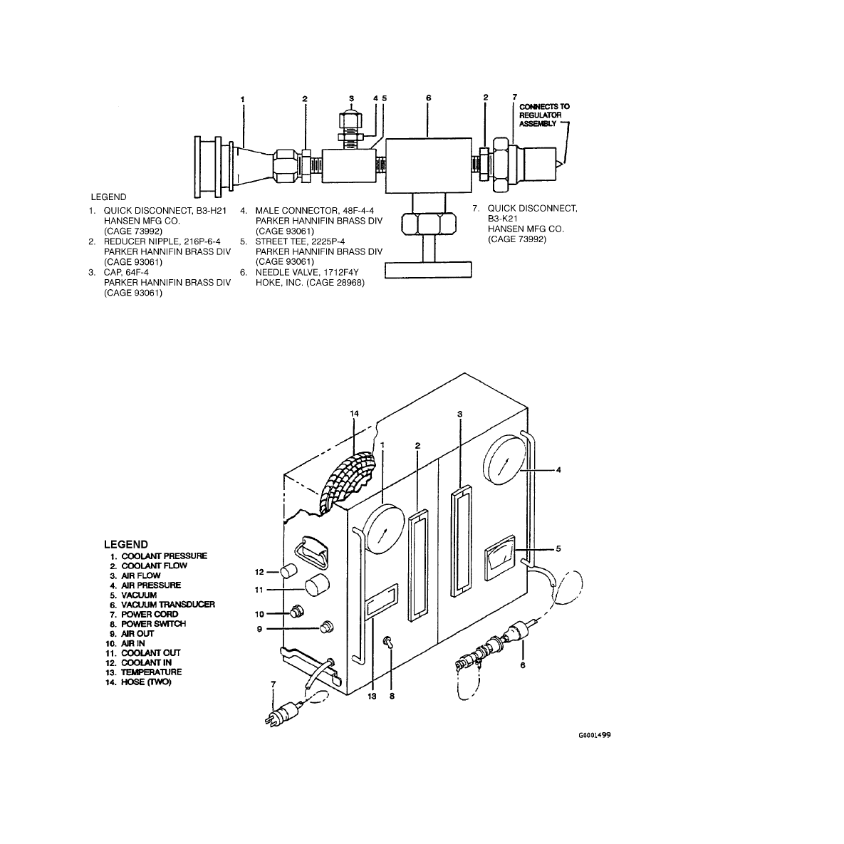
Figure 2-1. Nitrogen Adapter Assembly
Figure 2-2. Test Stand Used with A/E47T-23
T.O. 33D9-17-89-1
2-3/(2-4 blank)


CHAPTER 3
PREPARATION FOR USE AND SHIPMENT
3.1
SHIPPING AND STORAGE REQUIREMENTS.
The test bench motions, such as those encountered during shipping or warehouse handling, require the following items to be
removed and packaged separately:
a.
Refrigerant cylinder (Figure 5-1, 76).
b.
Cylinder band heater, including pressure switch PS-1 (74) and temperature switch TS-1 (75).
c.
Photoelectric controller PEC-1 (56).
d.
Photoelectric controller PEC-3 (55).
e.
All cable, hose, adapter, and test assemblies that are part of the test bench and normally stored in the test bench
drawers. See Figure 1-1.
f.
The test stand assembly, Figure 2-2.
3.1.1
Vacuum Manometer Gauge.
In addition, the tube sealing mechanism shall be installed in the vacuum manometer
gauge, Figure 3-1, and all water shall be drained from test bench and test stand. Side panels, front door, and drawers shall be
secured in place.
T.O. 33D9-17-89-1
3-1
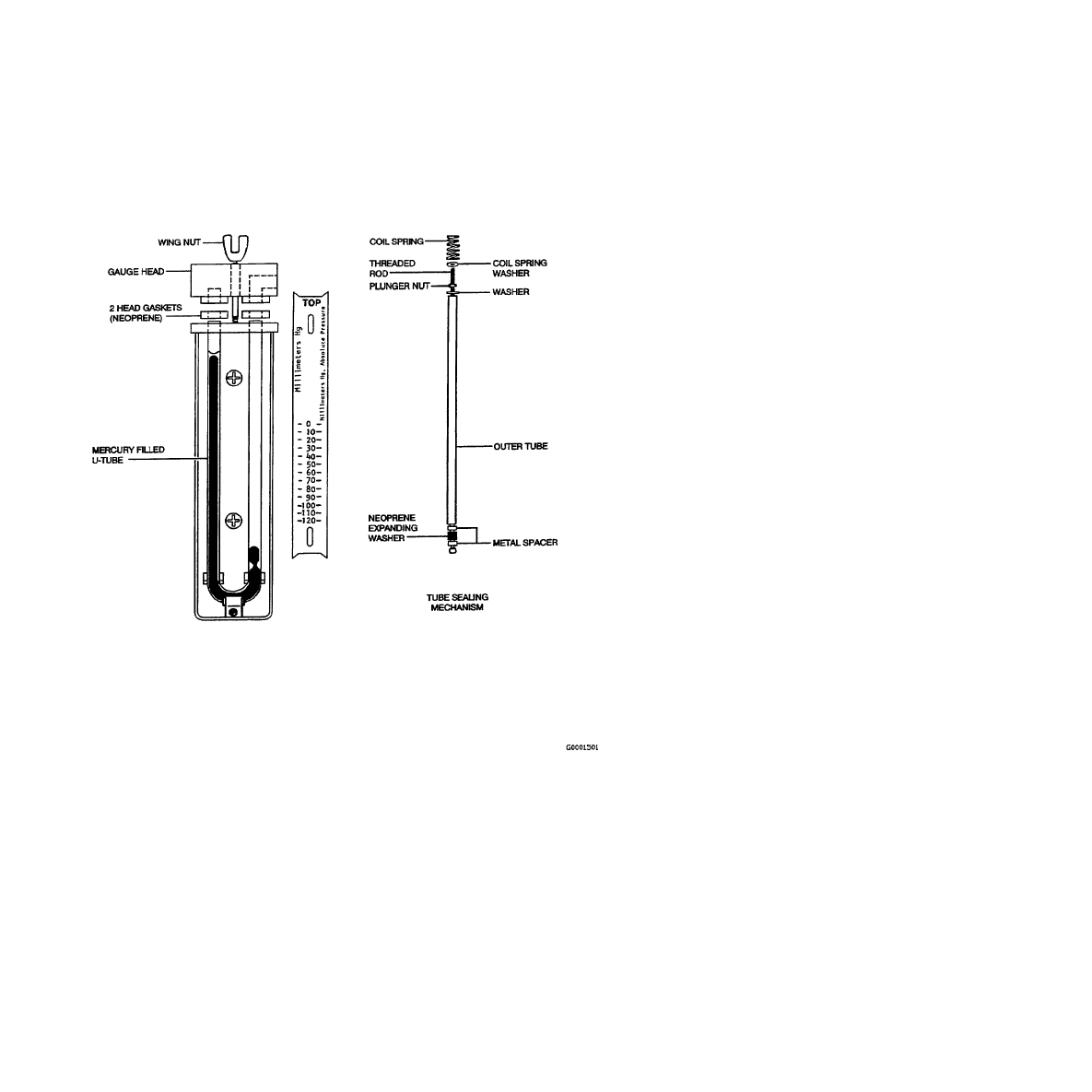
Figure 3-1. Manometer and Sealing Mechanism
T.O. 33D9-17-89-1
3-2

3.2
PREPARATION FOR USE.
If test bench has been transported, verify receipt of all packages. Remove packaging, inspect for damage, and check items
against shipping list. Verify that items listed in Paragraph 3.1 are included, and place items in Paragraph 3.1, step e, into the
test bench drawers.
3.2.1
Refrigerant Cylinder Installation.
a.
Install the band heater assembly onto the cylinder. Position the heater just above the cylinder base with the pres-
sure switch aligned to the approximate direction of the refrigerant valve outlet. Snap the band clamp closed.
b.
Put the blanket in place on the cylinder.
c.
Put the cylinder in the test bench and align the refrigerant valve outlet approximately toward the rear cabinet
centerpost.
d.
Install refrigerant pressure indicator assembly onto refrigerant valve outlet with indicator and liquid eye toward
the rear.
e.
Install one red hose to shutoff valve V7 (Figure 5-1, 78) and to end connector of refrigerant pressure indicator
assembly.
f.
Install the other red hose to side connector of refrigerant pressure indicator and to pressure switch (74).
g.
Connect the cable, part of (74), to J108 (58).
3.2.2
Photoelectric Controller Installation.
NOTE
The two photoelectric controllers are identical.
a.
Insert one photoelectric controller (PEC-3) into J101 (Figure 5-1, 55).
b.
Insert the other photoelectric controller (PEC-1) into J102 (56).
c.
Verify that cables are connected to J103 through J113. If a cable is disconnected and its connector marking is not
legible, refer to FO-4 for identity.
3.2.3
Manometer Gauge Preparation.
The manometer U-tube is fitted with a tube sealing mechanism, Figure 3-1,
which prevents mercury spillage during shipping or handling. The mechanism must be removed before the gauge can function:
a.
At rear of panel, disconnect vacuum line at top of manometer and remove mounting nuts. Front scale must be
removed to access bolt heads.
b.
Remove wingnut, gauge head, and two neoprene gauge head gaskets from manometer.
c.
Remove coil spring and washer from tube sealing mechanism. Grip end of threaded rod and back off plunger nut
about 1/4 inch to reduce expanding washer at bottom end of rod.
Potential mercury hazard exists. Be careful not to break the manometer U-tube. Failure to
comply may result in personnel injury.
d.
Carefully remove the sealing mechanism from the U-tube, avoiding entrainment of mercury.
e.
Reassemble and reinstall manometer.
f.
Store tube sealing mechanism in test bench drawer for future use.
3.2.4
Ground Connections.
The test bench has two ground studs, either of which may be used. Connect facility ground
to external ground stud on top or the one on the back, whichever is most convenient.
T.O. 33D9-17-89-1
3-3
3.2.5
Electrical Power and Compressed Air.
a.
Set the following circuit breakers on test bench to OFF:
400 Hz POWER CB2
60 Hz POWER CB1
60 Hz POWER CB4
b.
Connect test bench cables to facility electrical power.
c.
Close AIR PURGE valve and connect facility air to test bench.
3.2.6
Checkout.
Proceed to Chapter 5.
3.3
PREPARATION FOR SHIPMENT.
The following procedure will prepare the test bench for transportation.
a.
Disconnect the power cables, ground wire, and air hose.
b.
Remove the right-rear panel.
c.
Disconnect both hoses from the refrigerant pressure indicator assembly. Remove the pressure indicator assembly
and both hoses from the test bench.
d.
Disconnect pressure switch cable (Figure 5-1, 74) from J108 (58), and remove cylinder from test bench.
e.
Remove blanket and band heater assembly from the cylinder.
f.
Remove photoelectric controllers (55 and 56) from test bench.
3.3.1
Manometer Tube Sealing.
a.
Locate tube sealing mechanism (Figure 3-1), normally stored in test bench drawer, and verify plunger nut is
backed off enough so expanding washer is not compressed.
Potential mercury hazard exists. Be careful not to break the manometer U-tube. Failure to
comply may result in personnel injury.
b.
Remove manometer by disconnecting vacuum line and two mounting nuts at rear of panel. Front scale must be
removed to access bolt heads.
c.
Remove wingnut, gauge head, and two neoprene head gaskets from manometer.
d.
Very slowly insert sealing mechanism into right-hand leg of U-tube until it barely contacts mercury.
e.
Grip end of threaded rod and tighten plunger nut until expanding washer very snugly seals U-tube.
f.
Install coil spring washer, coil spring, two head gaskets, gauge head, and wingnut. Reinstall manometer.
3.3.2
Packing.
Remove assemblies from test bench drawers. All items in Figure 1-1 should be accounted for. These items,
special tools in Table 2-1, and items removed in Paragraph 3.3, steps c through f, are ready for packaging. Reinstall rear panel
of test bench, secure drawers, door, and side panels, and bench is ready for packaging. Package and transport in accordance
with applicable procedures.
T.O. 33D9-17-89-1
3-4

CHAPTER 4
OPERATION INSTRUCTIONS
4.1
THEORY OF OPERATION.
The test bench connects to facility electrical power and compressed air within the repair shop, and operation requires the test
equipment listed in Chapter 2. The test bench is otherwise self-contained since it has water and refrigerant storage tanks, and
it includes all necessary cables. Refer to schematics FO-1 and FO-2 and to control panel, Figure 4-1, for the following
paragraphs.
4.1.1
Electrical Power.
See FO-1. Two electrical cables enter the top of the cabinet and connect to terminal blocks.
Facility ground connects to a terminal atop the cabinet. One cable carries 60 Hz, 3-phase power which is routed through line
filter FL1 and CB1 to the following:
a.
COOLANT PUMP switch S1, which controls power to the pump motor and to the heater control panel A1. A1
receives 208 volts from phases A and B, and it controls the coolant temperature in the tank.
b.
Circuit breaker CB3 in left side of cabinet, which controls input power to two dc power supply modules PS1 and
PS2. These power supplies provide the necessary dc voltages to the electronic enclosure located above PS2.
c.
Coolant and compressed airflow transducer interface assemblies A2 and A3.
d.
All electronic digital meters M1 through M10.
e.
60 Hz POWER indicators and ac POWER outlet.
4.1.1.1
Phase Motor.
The other cable carries 400 Hz, 3-phase power which is routed through line filter FL2 and CB2;
the 400 Hz POWER indicators come on when CB2 is set to ON. The 400 Hz power passes through the variable transformer
T1, which controls voltage amplitude, and then through the PHASE MONITOR switch S4 to J1. Connector J1 supplies power
to the chiller, refrigerant compressor or coolant pump under test. The PHASE MONITOR switch selects each phase of 400
Hz power for frequency, voltage, and current readout on meters M8, M9, and M10. Meter M10 requires a current transformer
T2 (electronic transducer) to match the line to the ammeter circuit.
4.1.2
Coolant System.
See FO-1 and FO-2. The coolant system includes:
a.
A tank fitted with a drain cock and a 240V 2000W immersion-type heater.
b.
Temperature sensor RT1, which is monitored by an adjustable thermostat in the heater control panel A1, which in
turn controls the heater.
c.
Centrifugal pump, driven by a 120V 60 Hz motor.
d.
COOLANT PUMP switch that controls power to pump motor and heater control panel.
e.
Coolant filter and a manual supply valve V3, to adjust flow to chiller or control valve under test.
f.
Two coolant supply line transducers RT3, MT3, which sense temperature and pressure for display on meters M6
and M7, respectively, when a control valve or entire chiller is being tested.
g.
Three return line transducers RT2, MT2, and MT5 and meters M3, M4, and M5 which, respectively, sense and
display temperature, pressure, and flow of coolant from unit under test. The flowmeter M5 requires linearizer A2
to match it to transducer MT5.
4.1.2.1
Coolant Supply.
The chiller unit is tested by connecting it to 400 Hz power at J1 and to the coolant supply and
return lines. Coolant supply temperature and flow rate are adjusted as specified, and return temperature is compared with
specification. A coolant pump to be tested is mounted on top of the coolant tank connected to COOLANT IN and connected
to 400 Hz power at J1. The coolant return flow is adjusted as specified and the return pressure is compared with specification.
ac and dc modulating control valves to be tested are connected to COOLANT OUT, COOLANT IN, and electrical connector
J2. Coolant return flow is compared to specifications when control valve is operated to fully open and to fully closed states.
4.1.3
Purge Air.
See FO-1 and FO-2. Facility air from the inlet on top of the cabinet is reduced in pressure by a 20 psig
regulator and routed through shutoff valve V4 to the PURGE SUPPLY connector on the control panel. The air is used to purge
coolant from a chiller unit or a modulating control valve after test. When testing is completed on a chiller or control valve,
the hoses are disconnected at the panel from COOLANT IN and COOLANT OUT fittings, and they are connected to PURGE
SUPPLY and PURGE RETURN. Then AIR PURGE manual valve V4 is opened to force residual coolant to return to the tank.
T.O. 33D9-17-89-1
4-1

4.1.4
Compressor Air.
See FO-1 and FO-2. The compressor air originates from the compressor under test and enters the
control panel at the COMPRESSOR AIR RETURN fitting. The system includes a drain valve, relief valve, and an oil separator
which removes compressor oil from air being discharged inside the cabinet. Flow transducer MT4, range extender amplifier
A3, and FLOWmeter M2 provide monitoring of compressor discharge. COMPRESSOR AIR RETURN manual valve V1 is
used to restrict flow so compressor discharge pressure can be monitored by transducer MT1 and PRESSURE meter M1.
4.1.5
Control Valve Testing System.
Coolant is connected and controlled as described above, and coolant return flow
is monitored by transducer MT5, linearizer A2, and FLOWmeter M5 during control valve operation. Driving signals for ac
and dc modulating control valves, Figure 4-2, FO-1 and FO-5, are generated by independent signal generators within the
electronic enclosure. Power supply modules PS1/PS2 provide input power to the circuits, and CONTROL VALVE switch S3
enables the selected signal generator. Switch S3 also selects the desired signal generator output. CONTROL VALVE
OPEN/OFF/CLOSE switch S3 controls the sequence of pulses generated by the dc signal generator, and it controls the inputs
to both control valve types. Capacitor C20 shifts current phase for ac valve motor operation. Testing a control valve requires
prior setting of S3 to prevent damaging the control valve motor. Connector J2 is the electrical input to both control valve types.
When driving signals are applied to a dc valve, indicators DS5, DS6, DS7, and DS8 flicker in sequence, indicating driving
signals are present and in correct order. When driving signals are issued to a 400 Hz valve, indicator DS3 or DS4 flickers to
indicate that the driving signals are present and are switched to the correct motor winding.
4.1.6
Evacuation and Refrigerant Charging System.
See FO-2, FO-3, and Figure 4-3. A chiller unit is charged by first
evacuating it to a sufficiently low pressure and then allowing it to draw in a measured volume of refrigerant. Controls and
gauges for testing, evacuating, and charging the chiller unit are on the right-hand panel. Inside the test bench are the wiring,
plumbing, valves, vacuum pump, and refrigerant cylinder. A circuit breaker, 60 Hz POWER CB4, controls power to the entire
evacuation and refrigerant charging system. The PANEL POWER switch, TGS-2, switches the 60 Hz, phase C to all system
components except the vacuum pump; thus the pump can run when only CB4 and VACUUM PUMP switch TGS-1 are turned
on. The vacuum pump evacuates the chiller, and when the pump is turned off, the vacuum break, solenoid valve SOL-B, opens
to vent the pump suction preventing oil from being drawn into the chamber.
4.1.6.1
Evacuation.
With VACUUM PUMP switch ON and function switch RSS-2 set to EVACUATE, solenoid valves
SOL-V/V8 and SOL-P/V9 energize/open to evacuate chiller in preparation for either pressure testing or charging. Vacuum
pressure can initially be monitored on the mercury manometer in both barometric and absolute. Higher vacuum pressure in
millimeters of mercury, absolute (mm Hg, abs.), is monitored on the panel gauge. Since 1 inch = 25.4 mm and 1 mm = 1000
microns, a refrigerant charging vacuum of 100 microns Hg absolute is a relatively low pressure (high vacuum).
4.1.6.2
Charging.
Prior to charging the refrigerant unit with refrigerant, the correct volume of refrigerant is filled into the
measuring tube, and since volume is affected by temperature, the refrigerant temperature in the cylinder and measuring tube
is controlled. The CYLINDER HEATER switch TGS-3 and MEASURING TUBE HEATER switch TGS-4 are turned on, and
the TUBE HEATER indicator comes on until the correct pressure is attained. The CYLINDER HEATER indicator comes on
but will cycle after pressure is attained. At operating pressure, PRESSURE switch PS-2 closes, energizing relay CR-H to turn
off the tube heater and to enable the charging circuits. Now, when the REFRIGERANT MEASURING TUBE switch RSS-1
is momentarily set to FILL, relay CR-F closes to energize/open solenoid valve SOL-F/V11, allowing refrigerant to flow into
the measuring tube. When the tube is nearly full, the upper photoelectric detector/controller valve, PD-1/PEC-1, opens CR-F
to close SOL-F/SOL-E to stop the flow. With RSS-2 set to CHARGE, RSS-1 can be momentarily set to CHARGE to close
relay CR-C, to energize/open solenoid valve SOL-C/V10, transferring refrigerant from measuring tube to chiller unit by
vacuum pressure. The lower photoelectric detector/controller, PD-3/PEC-3, opens CR-C to close SOL-C/V10 to stop the flow
after the measured volume has been transferred.
4.1.6.3
Gas Ballast and Purge.
The GAS BALLAST valve V17 slightly vents the vacuum pump ahead of the discharge
valves to reduce the exhaust pressure change; therefore, reducing or eliminating water condensation within the pump. Water
in the vacuum pump causes oil emulsification, reduced efficiency, and discharge valve noise. However, since the ballast gas
(air), at atmospheric pressure, is entering the pump chamber too much gas ballast can make it impossible to attain a very low
pressure such as 100 microns Hg, abs.
T.O. 33D9-17-89-1
4-2
4.2
OPERATION.
Operational procedures for the test bench, during the testing and maintenance of the G&C chiller unit or its components, are
described in T.O. 35E9-35-22.
Facility ground wire, electrical cables, and air shall be connected before operating. Failure
to comply may result in equipment damage.
4.2.1
Preoperational Checkout.
Ensure facility ground wire, electrical cables, and air are connected. Check the drawer
for the cable and hydraulic hose assemblies needed for OGE testing. Perform the preoperational checkout procedures, Table
4-1 or Table 4-2, as required, to be sure bench is operational. If any steps of the preoperational checkout fail, proceed to
maintenance instructions in Chapter 5.
T.O. 33D9-17-89-1
4-3
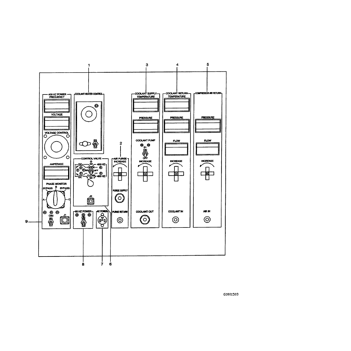
Figure 4-1. Left Control Panel (Sheet 1 of 3)
T.O. 33D9-17-89-1
4-4

No.
Control/Indicator
Function
1.
COOLANT HEATER
CONTROL (A1)
Potentiometer
Adjusts temperature of water in coolant tank.
Indicator
On during heater-on cycle.
Switch
Controls power to heater controls when CB1 and S1 are on.
Fuse - 15 amp
Protects circuitry in heater control panel (A1).
2.
AIR PURGE
Valve (V4)
Controls air to PURGE SUPPLY fitting.
PURGE SUPPLY fitting
Connects to chiller unit or control valve to be purged of coolant.
PURGE RETURN fitting
Returns purged coolant to tank.
3.
COOLANT SUPPLY
TEMPERATURE meter (M6)
Displays temperature of coolant to chiller unit or control valve
under test.
PRESSURE meter (M7)
Displays coolant pressure at input of unit under test.
COOLANT PUMP S1 switch and
indicators
Switch controls 120 volts to pump and 208 volts to heater control.
Indicators are on the two phases of 208 volts.
Valve (V3)
Controls coolant supply flow when pump is running.
COOLANT OUT fitting
Input to chiller unit or control valve under test.
4.
COOLANT RETURN
TEMPERATURE meter (M3)
Displays temperature of coolant from chiller unit or control valve
under test.
PRESSURE meter (M4)
Displays coolant pressure at output of unit under test.
FLOW meter (M5)
Indicates coolant flow rate through unit under test.
Valve (V2)
Used to control or restrict coolant return flow.
COOLANT IN fitting
Output from unit under test.
5.
COMPRESSOR AIR RETURN
PRESSURE meter (M1)
Indicates discharge pressure from compressor under test.
FLOW meter (M2)
Indicates discharge flow from compressor under test.
Valve (V1)
Used to control or restrict discharge of compressor under test.
AIR IN fitting
Output from unit under test.
Figure 4-1. Left Control Panel (Sheet 2)
T.O. 33D9-17-89-1
4-5
No.
Control/Indicator
Function
6.
CONTROL VALVE
Switch S2
Selects driving signals to open or close either type control valve.
Normally set to OFF.
400 Hz indicators (DS3, DS4)
OPEN or CLOSE flickers to indicate driving signals when 400 Hz
control valve is operated.
DC indicators (DS5 - DS8)
All four flicker in sequence to indicate driving signals when dc
control valve is operated.
S3 must be set correctly before S2 is operated to prevent damage to control valve motor.
Switch S3
Selects type of control valve to be tested - dc or 400 HZ.
Connector J2
Connects control valve to be tested.
7.
AC POWER outlet (J3)
120 Vac 60 Hz available when CB1 is on.
8.
60 Hz POWER
Indicators (DS9-DS11)
Indicate presence of each phase.
Circuit breaker CB1
Controls all 60 Hz power to left side of test bench.
9.
400 Hz POWER
FREQUENCY meter (M8)
Displays frequency of selected phase.
VOLTAGE meter (M9)
Displays RMS voltage of selected phase.
VOLTAGE CONTROL (T1)
Adjusts voltage across load from zero to 120.
AMPERAGE meter (M10)
Displays current through load of selected phase.
PHASE MONITOR switch (S4)
Selects phase for display of frequency, voltage and current.
BYPASS settings bypass the displays and provides isolation
between phases during switching.
Indicators (DS12 - DS14)
Indicate presence of each phase at input of voltage control.
Circuit breaker CB2 Connector
J1
Controls all 400 Hz power to test bench. Supplies power to the
chiller, refrigerant compressor, or coolant pump under test.
Figure 4-1. Left Control Panel (Sheet 3)
T.O. 33D9-17-89-1
4-6
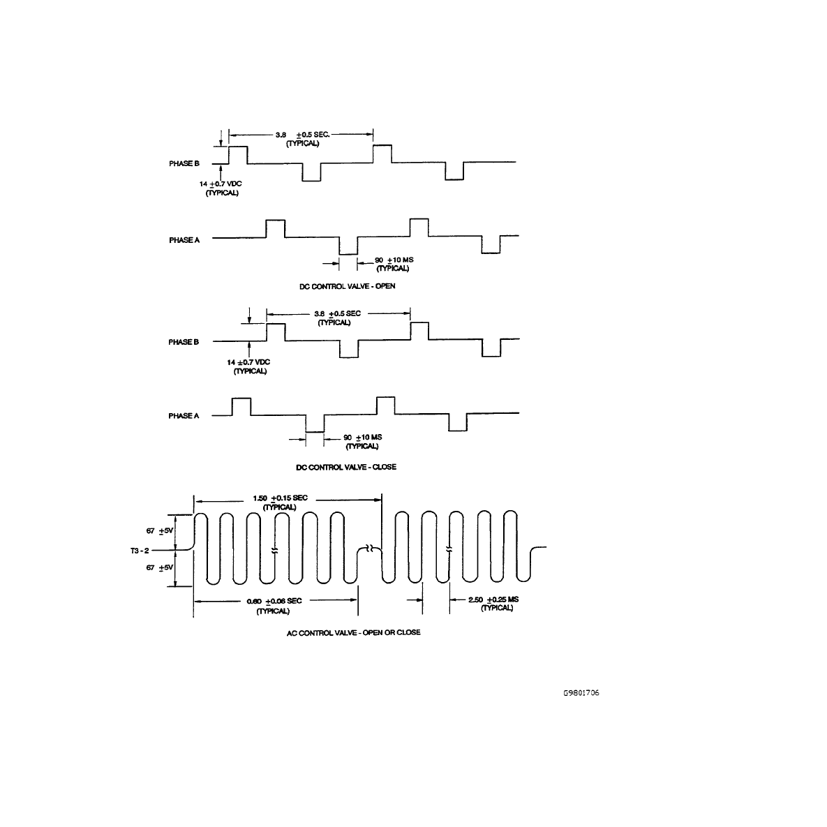
Figure 4-2. Control Valve Driving Signals
T.O. 33D9-17-89-1
4-7
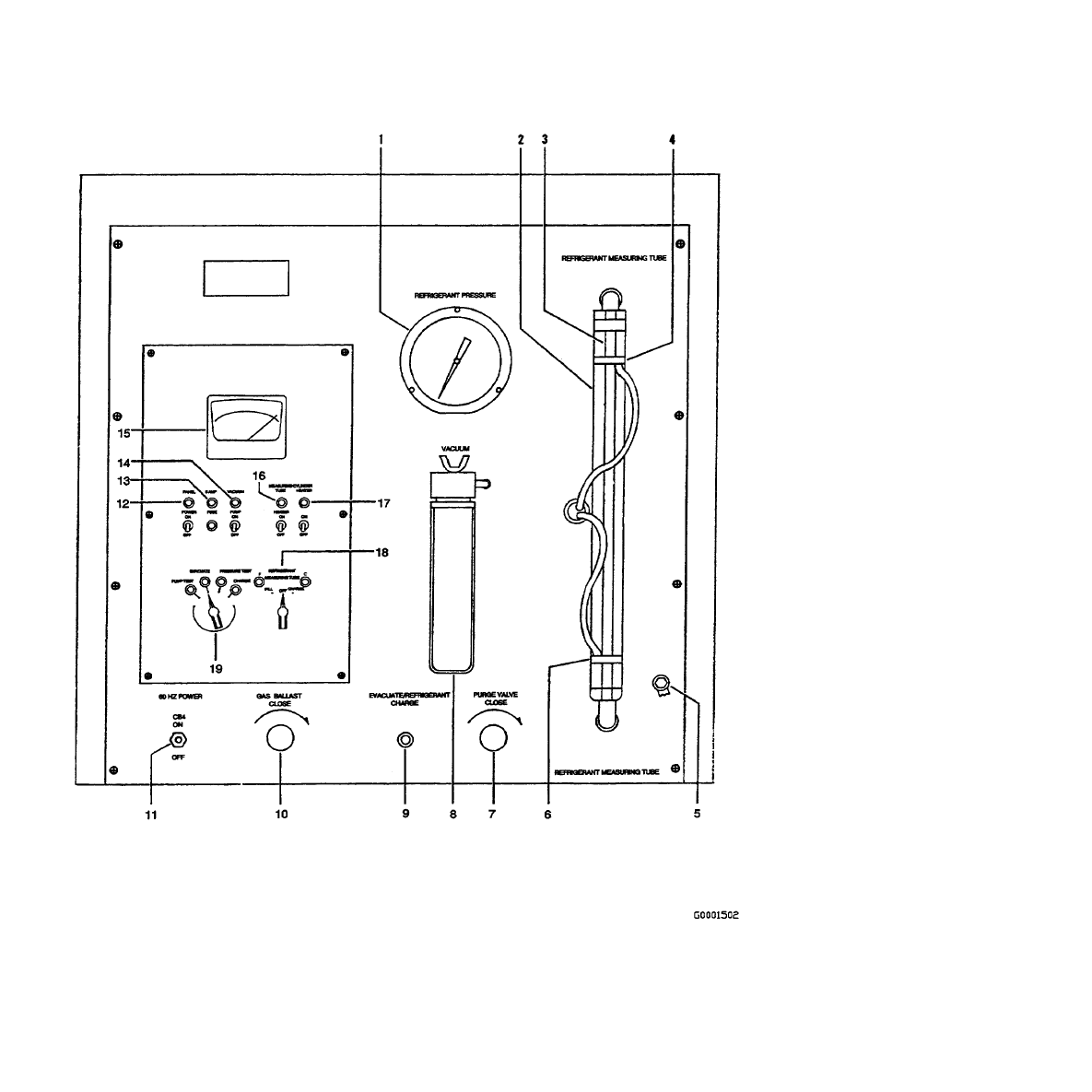
Figure 4-3. Right Control Panel (Sheet 1 of 3)
T.O. 33D9-17-89-1
4-8

No.
Control/Indicator
Function
1.
REFRIGERANT PRESSURE
gauge
Displays pressure in refrigerant measuring tube.
2.
Scale
Provides reference for adjusting the sight-gauge light beams.
3.
Sight-gauge
Displays level of refrigerant in refrigerant measuring tube.
4.
Upper sight-gauge light
beam assembly (PEC-1)
Causes solenoid valves SOL-F/V11 and SOL-E/V13 to close by
de-energizing relay CR-F when measuring tube is filled.
5.
Ground stud and cable
Provides grounding for equipment under test.
6.
Lower sight-gauge light
beam assembly (PEC-3)
Causes solenoid valve SOL-C/V10 to close by de-energizing relay CR-C
when measured volume of refrigerant has been transferred from test
bench.
7.
PURGE VALVE (V5)
Provides for release of refrigerant from chiller unit and from test bench.
8.
REFRIGERANT VACUUM
manometer gauge
Displays vacuum in millimeters of mercury (Hg), absolute pressure.
9.
EVACUATION/
REFRIGERANT CHARGE
fitting
Connects to chiller unit for evacuation or charging.
10.
GAS BALLAST valve (V17) Provides for ballasting the vacuum pump exhaust chamber with small
amount of air to eliminate condensation.
11.
60 Hz POWER CB4 circuit
breaker
Controls 120 Vac, 60 Hz power to right side of test bench - independent
of CB1 on left side.
12.
PANEL POWER switch with
indicator (TGS-2/NLT-2)
Switch controls 120 Vac, 60 Hz power to all controls on service station
panel except VACUUM PUMP switch. Indicator comes on with power.
13.
5 AMP fuse with indicator
(FU-5/NLT-5)
Provides protection of low-current circuits controlled by service station
panel (not of motor or heater circuits). Indicator comes on if fuse fails.
14.
VACUUM PUMP switch
with indicator
(TGS-1/NLT-1)
Switch controls 120 Vac, 60 Hz power to pump motor and vacuum break
solenoid valve. When motor is turned off, vacuum break valve opens to
relieve vacuum in pump. Indicator comes on with pump.
15.
Vacuum gauge (M-4)
Displays vacuum at lower pressures - down to about 20 microns Hg,
abs.; one micron equals 0.001 millimeter.
16.
MEASURING TUBE
HEATER switch with
indicator (TGS-4/NLT-4)
Switch controls power to heater control circuits. Indicator goes out when
refrigerant is ready for charging, indicating charging circuits are enabled.
17.
CYLINDER HEATER
switch with indicator
(TGS-3/NLT-3)
Switch controls power to heater control circuits. Indicator and heater
cycle OFF and ON as refrigerant temperature is maintained.
Figure 4-3. Right Control Panel (Sheet 2)
T.O. 33D9-17-89-1
4-9
No.
Control/Indicator
Function
18.
REFRIGERANT
MEASURING TUBE switch
with indicators RSS-1/NLT-6,
NLT-7):
Switch is spring-loaded to OFF and requires only momentary actuation.
Indicators F and C come on during respective operation.
FILL position
FILL causes solenoid valves SOL-F/V11 and SOL-E/V13 to open, filling
measuring tube.
CHARGE position
When refrigerant in measuring tube is ready, CHARGE causes solenoid
valve SOL-C/V10 to open, transferring refrigerant from measuring tube
to chiller unit.
19.
Function selector switch with
indicators (RSS-2/NLT-8,
NLT-11):
Indicator comes on for each switch position.
PUMP TEST position
Solenoid valve SOL-V/V8 opens to connect vacuum pump suction to
manometer and vacuum gauge.
EVACUATE position
Solenoid valves SOL-V/V8 and SOL-P/V9 open to connect vacuum
pump suction to gauges and to chiller unit.
PRESSURE TEST position
Solenoid valve SOL-P/V9 opens, and SOL-V/V8 closes, so vacuum in
chiller can be monitored after evacuation. Test bench can also be tested
for leaks if chiller unit is not connected.
CHARGE position
When refrigerant in measuring tube is ready, CHARGE causes solenoid
valve SOL-C/V10 to open, transferring refrigerant from measuring tube
to chiller unit.
Figure 4-3. Right Control Panel (Sheet 3)
T.O. 33D9-17-89-1
4-10

Table 4-1. Preoperational Checkout - Left Panel
Procedure
Observation
NOTE
Shop ambient temperature is required to be between 60 and 80 °F.
1.
Set switches S1 and S2 and circuit breakers CB1 and CB2
to OFF.
2.
Verify that coolant tank is filled two to four inches from its
top with distilled water. If tank was previously drained and
left empty, be sure drain valve on tank is closed.
Water should be clear and free of
contamination.
NOTE
Allow test equipment to warm up for 10 minutes prior to testing.
3.
Turn on 60 Hz POWER CB1.
Three 60 Hz POWER indicators come on.
Verify all 10 digital panel meters illuminate;
type of illumination is not significant.
4.
Set PHASE MONITOR switch to BYPASS.
5.
[1] [1X] Set master power circuit breaker to motor
generator to ON.
6.
[1] [1X] Prior to power up of the motor generator, set
variable power transformer to HIGH position.
7.
[1] [1X] Set start switch on motor generator control box to
START.
8.
Turn on 400 Hz POWER CB2.
Three 400 Hz POWER indicators come on.
VOLTAGE, FREQUENCY, and AMPERAGE
meters indicate approximately zero.
NOTE
[1] [1X] If frequency is out of tolerance, adjust variable transformer for correct frequency.
Transformer is located by 400 Hz generator.
9.
Set PHASE MONITOR switch to A and rotate VOLTAGE
CONTROL.
VOLTAGE meter indicates voltage is adjustable
through range of 0 to more than 120 VOLTS
AC, FREQUENCY meter indicates 400 (±10)
Hz, and AMPERAGE meter indicates
approximately zero.
10.
Repeat step 9 with PHASE MONITOR switch set to B and
to C.
11.
Set PHASE MONITOR switch to A.
12.
Set VOLTAGE CONTROL to 0.
T.O. 33D9-17-89-1
4-11
Table 4-1. Preoperational Checkout - Left Panel - Continued
Procedure
Observation
13.
Set PHASE MONITOR switch to BYPASS.
14.
Set 400 Hz POWER CB2 to OFF.
15.
[1] [1X] Set start-stop switch on 400 Hz motor generator
control panel to STOP.
16.
Observe meters for COOLANT SUPPLY, COOLANT
RETURN, and COMPRESSOR AIR RETURN.
Flowmeters indicate approximately zero,
temperature indications depend on ambient
temperature, and pressure indications are not
significant.
When closing manual shutoff valves, use of excessive force can damage valve seats.
17.
Check the following valves for free operation and close
them by turning fully clockwise:
AIR PURGE
COOLANT SUPPLY
COOLANT RETURN
COMPRESSOR AIR RETURN
18.
Set COOLANT PUMP switch to ON.
Two COOLANT PUMP indicators come on and
coolant pump can be heard or felt to be running
19.
On COOLANT HEATER CONTROL panel, set toggle
switch to ON.
Indicator on COOLANT HEATER CONTROL
panel may come on depending on temperature
of water in tank and setting of thermostat
control on panel. If necessary, increase thermo-
stat setting to check out indicator.
20.
Turn off COOLANT PUMP and COOLANT HEATER
CONTROL switches.
21.
Set CONTROL VALVE selector switch S3 to DC; set
CONTROL VALVE OPEN-OFF-CLOSE switch S2 to
OPEN and to CLOSE.
Four dc indicators go on and off in correct
sequence to indicate selected operation.
NOTE
If OPEN and CLOSE indicators do not come on, remove left-rear panel and verify that circuit breaker
CB3 (Figure 5-1, 24) is pushed in.
22.
Set 60 Hz POWER CB1 to OFF.
T.O. 33D9-17-89-1
4-12
Table 4-2. Preoperational Checkout - Right Panel
Procedure
Observation
•
Do not leave MEASURING TUBE HEATER switch on when measuring tube is empty. Equipment
damage will occur.
•
When closing manual shutoff valves, use of excessive force can damage valve seats.
1.
Set right-hand panel controls as follows:
60 HZ POWER CB4 - ON
Indicator on
PANEL POWER switch - ON
Indicator on
CYLINDER HEATER switch - ON
Indicator on
MEASURING TUBE HEATER switch - ON
Indicator on
MEASURING TUBE HEATER switch - OFF
Indicator off
VACUUM PUMP switch - OFF
Indicator off
PURGE valve - closed
GAS BALLAST valve - closed
2.
Remove right-rear panels.
3.
Open LIQUID valve on freon cylinder two turns from fully
closed.
4.
Open valves V6 (Figure 5-1, 82) and V7 (78) 1-1/2 turns
from fully closed.
REFRIGERANT PRESSURE gauge on cylinder
indicates pressure (pressure varies with
temperature). Liquid eye displays liquid in line.
5.
Check sight glass on vacuum pump.
Oil level must be 1/4 inch minimum above bottom
of sight glass.
6.
Set function selector switch to PUMP TEST.
PUMP TEST indicator comes on.
7.
Turn on VACUUM PUMP switch.
VACUUM PUMP indicator comes on and vacuum
pump starts. REFRIGERANT VACUUM
manometer and vacuum meter indicate a
vacuum pressure.
T.O. 33D9-17-89-1
4-13

Table 4-2. Preoperational Checkout - Right Panel - Continued
Procedure
Observation
NOTE
Gas ballast should be open to prevent moisture condensation inside pump. However, if 100 microns or
less cannot be attained, slowly close GAS BALLAST valve until knocking can be heard in vacuum
pump. Open GAS BALLAST valve until knocking is not heard.
8.
Open GAS BALLAST valve about two turns.
VACUUM gauge should indicate 100 microns or
less within 5 minutes.
9.
Turn off VACUUM PUMP switch.
10.
Close GAS BALLAST valve.
11.
Set function selector switch to EVACUATE.
EVACUATE indicator comes on.
12.
Set function selector switch to PRESSURE TEST.
PRESSURE TEST indicator comes on.
13.
Set function selector switch to CHARGE.
CHARGE indicator comes on.
14.
Set CYLINDER HEATER switch to OFF.
15.
Set PANEL POWER switch to OFF.
16.
Set 60 Hz POWER CB4 to OFF.
VACUUM gauge pointer settles on center of three
dots at right. Manometer indicates about 120 mm.
17.
Close LIQUID valve on freon cylinder.
18.
Replace rear panels.
19.
Check valve V13.
Valve V13 should be fully closed. Opening of
V13 during charging will allow refrigerant vapor
to be vented to the atmosphere.
T.O. 33D9-17-89-1
4-14

CHAPTER 5
MAINTENANCE INSTRUCTIONS
5.1
SCOPE.
This chapter contains procedures to checkout, troubleshoot, and repair the test bench. Ordinary hand tools and the equipment
listed in Table 2-1 are required. Table 5-1 through Table 5-5 include checkout of the functional test bench subsystems. If a
checkout step fails, refer to a related troubleshooting step in one of Table 5-6 through Table 5-10. Troubleshooting tables are
also arranged by functional subsystems, and the steps suggest faulty or out-of-adjustment part that would cause the failure.
After making an adjustment, repeat the checkout step that failed. After a repair, repeat the procedure.
5.1.1
Component Location.
Refer to Figure 4-1 and Figure 4-3 for location and function of front panel components. For
location of components within the test bench, refer to Figure 5-1.
5.2
REPAIR.
The Remedy column in the troubleshooting tables usually includes the procedures to make the repair, since there are no
requirements beyond common shop practice.
T.O. 33D9-17-89-1
5-1
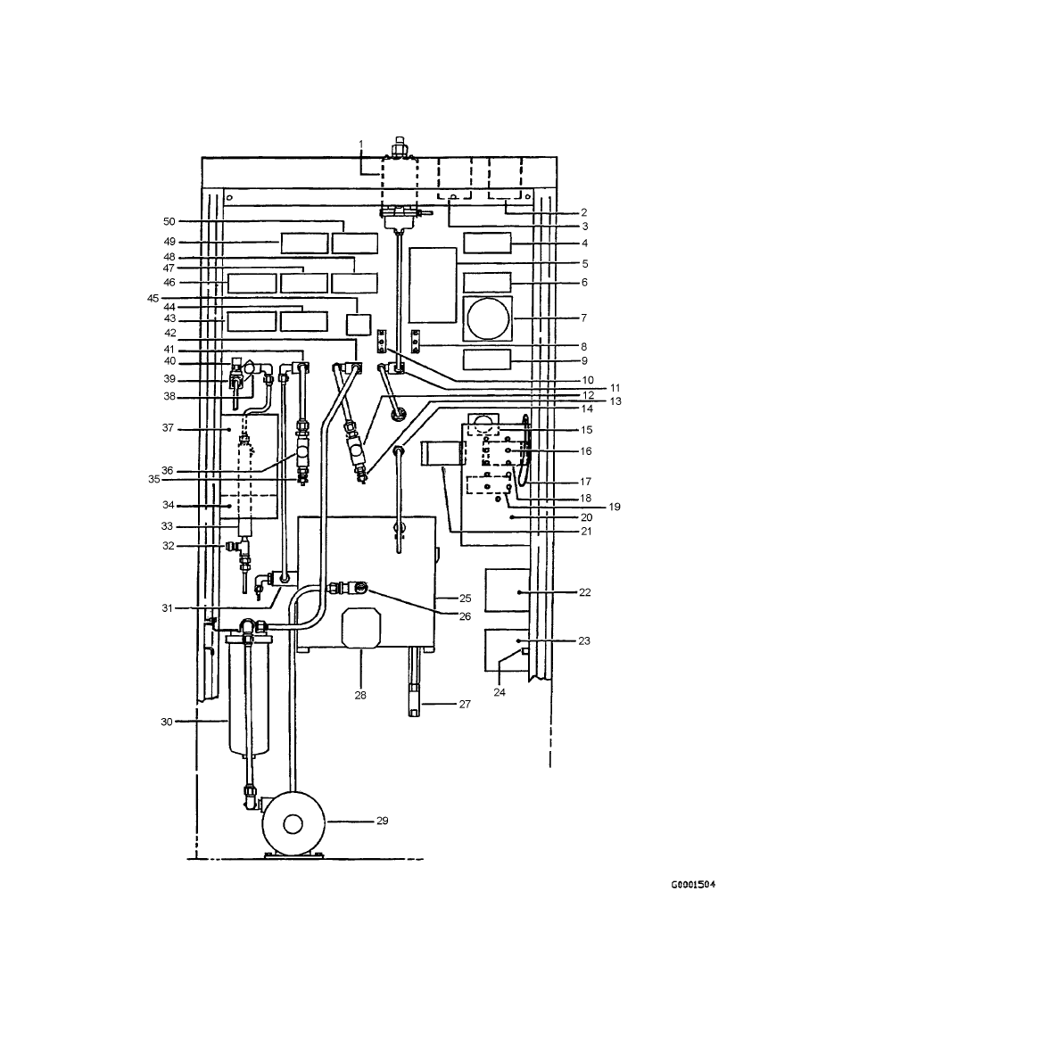
Figure 5-1. Test Repair Set Component Locations (Sheet 1 of 5)
T.O. 33D9-17-89-1
5-2
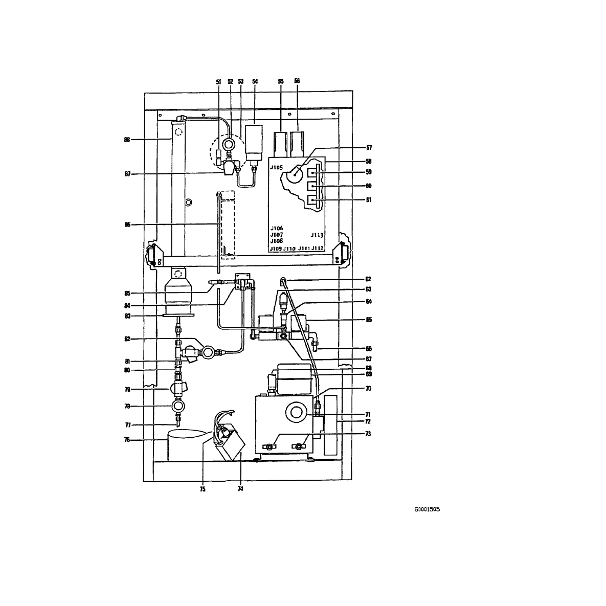
Figure 5-1. Test Repair Set Component Locations (Sheet 2)
T.O. 33D9-17-89-1
5-3

Number
Component
1.
V16, air pressure regulator
2.
FL1, 208 Vac 3-phase 60 Hz filter
3.
FL2, 208 Vac 3-phase 400 Hz filter
4.
M8, 400 Hz POWER-FREQUENCY meter
5.
A1, COOLANT HEATER CONTROL panel
6.
M9, 400 Hz POWER-VOLTAGE meter
7.
T1, 400 Hz POWER-VOLTAGE CONTROL transformer
8.
TB1, terminal strip - 60 Hz neutral
9.
M10, 400 Hz POWER-AMPERAGE meter
10.
TB2, terminal strip - 60 Hz phase C
11.
V4, air purge shutoff valve
12.
MT3, coolant supply pressure sensor
13.
RT3, coolant supply temperature sensor
14.
Air purge return assembly
15.
S4, 400 HZ POWER - PHASE MONITOR switch
16.
J4 through J14, test jacks for PS1, PS2, and electronic enclosure circuits
17.
Wire loop, test point for testing 400 Hz current with clamp on ammeter
18.
CB2, 400 Hz POWER circuit breaker
19.
T2, 400 Hz current transducer
20.
Electronic enclosure
21.
CB1, 60 Hz POWER circuit breaker
22.
PS2, dc power supply
23.
PS1, dc power supply
24.
CB3, circuit breaker at input of PS1 and PS2
25.
Coolant tank
26.
RT1, coolant temperature sensor
27.
Coolant tank drain valve
28.
HR1, coolant heater assembly
29.
Coolant pump and motor assembly
30.
Coolant filter
Figure 5-1. Test Repair Set Component Locations (Sheet 3)
T.O. 33D9-17-89-1
5-4

Number
Component
31.
MT5, coolant return flow transducer
32.
V18, compressor air return relief valve - 250 psi
33.
Oil separator, compressor air return
34.
A3, range extending amplifier
35.
RT2, coolant return temperature sensor
36.
MT2, coolant return pressure sensor
37.
A2, linearizer
38.
V1, compressor air return flow transducer
39.
MT4, compressor air return transducer
40.
MT1, compressor air return pressure sensor
41.
V2, coolant return shutoff valve
42.
V3, coolant supply shutoff valve
43.
M2, COMPRESSOR AIR RETURN FLOW meter
44.
M5, COOLANT RETURN FLOW meter
45.
S1, COOLANT PUMP switch
46.
M1, COMPRESSOR AIR RETURN PRESSURE meter
47.
M4, COOLANT RETURN PRESSURE meter
48.
M7, COOLANT SUPPLY PRESSURE meter
49.
M3, COOLANT RETURN TEMPERATURE meter
50.
M6, COOLANT SUPPLY TEMPERATURE meter
51.
V14, refrigerant pressure relief valve - 235 psi
52.
V13, shutoff valve
53.
REFRIGERANT PRESSURE gauge
54.
PS-2, pressure switch
55.
PEC-3 (J101), photoelectric controller-charge (J103 top front)
56.
PEC-1 (J102), photoelectric controller-fill (J104 top front)
57.
M4, vacuum meter-adjustment screw on top
58.
PC2BA, program control center
59.
CR-H, tube heater relay
60.
CR-C, charge relay
61.
CR-F, fill relay
Figure 5-1. Test Repair Set Component Locations (Sheet 4)
T.O. 33D9-17-89-1
5-5

Number
Component
62.
V17, GAS BALLAST valve
63.
SOL-P/V9, evacuate and pressure test solenoid valve
64.
PT-4, vacuum transducer
65.
SOL-V/V8, vacuum solenoid valve
66.
Suction line from vacuum pump
67.
Cap-test stand transducer connection
68.
Suction line to oil dropout tank and vacuum breaker solenoid valve, SOL-B
69.
Oil mist, eliminator
70.
Vacuum pump
71.
Oil level sight glass
72.
Drive belt pulley guard
73.
Oil drain valves
74.
PS-1, refrigerant cylinder pressure switch
75.
TS-1, refrigerant cylinder temperature switch
76.
Refrigerant cylinder
77.
Hose from refrigerant cylinder
78.
V7, shutoff valve
79.
SOL-F/V11, fill solenoid valve
80.
V15, check valve
81.
SOL-C/V10, charge solenoid valve
82.
V6, shutoff valve
83.
Measuring tube heater base plate
84.
EVACUATE/REFRIGERANT CHARGE fittings
85.
V5, PURGE VALVE
86.
VACUUM manometer gauge
87.
SOL-E/V12, measuring tube vent solenoid valve
88.
Measuring tube assembly
Figure 5-1. Test Repair Set Component Locations (Sheet 5)
T.O. 33D9-17-89-1
5-6

Table 5-1. Power Checkout
Step
Operation
Normal Indication
Trouble Ref.
1.
Set 60 Hz POWER CB1 ON.
60 Hz POWER indicators come on.
1.
2.
Set START-STOP switch on 400 Hz
generator control box to START.
3.
Set 400 Hz POWER CB2 ON.
400 Hz POWER indicators come on.
1.
4.
Set PHASE MONITOR switch to A
and set VOLTAGE CONTROL to
acquire 120-volt indication on 400 Hz
POWER VOLTAGE meter.
400 Hz POWER VOLTAGE meter M9 indicates
120 (±2.5) volts.
3.
5.
Set 400 Hz POWER CB2 OFF.
NOTE
Allow 10-minute warm-up for digital meters in test bench.
6.
Set PHASE MONITOR switch to
BYPASS.
7.
Connect cable 25-79312-2 to 400 Hz
POWER J1.
NOTE
Ensure that connector adapter is clocked to keyway position 2.
8.
Connect connector adapter
BACC45HR12-01P to cable end.
9.
Connect phase meter to connector
adapter pins 1, 2, 3 (phase A, B, C,
respectively).
10.
Set 400 Hz POWER CB2 ON.
Indicated phase sequence is A-B-C.
Miswiring
during
repair.
Reverse any
two of phase
wires at
input side of
FL2.
11.
Set 400 Hz POWER CB2 OFF and
disconnect phase meter from
connector adapter.
12.
Set PHASE MONITOR switch to
PHASE A and connect multimeter to
connector adapter pin 1 and to ground
stud (Figure 4-3, 5).
T.O. 33D9-17-89-1
5-7

Table 5-1. Power Checkout - Continued
Step
Operation
Normal Indication
Trouble Ref.
13.
(Deleted)
14.
Set 400 Hz POWER CB2 ON and
vary VOLTAGE CONTROL knob.
Voltage varies smoothly from about zero to at least
120 Vac.
2.
NOTE
If using a multimeter capable of reading frequency, steps 19 and 20, may be
performed in conjunction with the performance of steps 15 and 16. If completed this
way, disregard performing steps 17 and 18, and proceed to step 21 after correct indi-
cations are obtained for both voltage and frequency readings.
15.
Set VOLTAGE CONTROL to acquire
120 volt indication on multimeter.
400 Hz POWER VOLTAGE meter M9 indicates
120 (±2.5) volts.
3.
16.
Repeat steps 14 and 15 for phases B
and C at connector adapter pins 2 and
3, respectively.
3.
17.
Set 400 Hz POWER CB2 OFF and
disconnect multimeter from connector
adapter.
18.
Set PHASE MONITOR switch to
PHASE A and connect frequency
counter to connector adapter pin 1 and
to ground cable.
19.
Set 400 Hz POWER CB2 ON and Set
VOLTAGE CONTROL knob to 120
Vac.
Indications on frequency counter and 400 Hz
POWER FREQUENCY meter M8 are within 3 Hz.
3.
20.
Repeat steps 18 and 19 for phases B
and C at connector adapter pins 2 and
3, respectively.
21.
Set VOLTAGE CONTROL fully
counterclockwise.
22.
Set 400 Hz POWER CB2 OFF and
disconnect frequency counter,
connector adapter.
23.
Connect chiller unit for load at end of
cable 25-79312-2. Connect ground
cable (Figure 4-3, 5) to chiller unit.
24.
Connect clamp-on ammeter onto wire
loop (Figure 5-1, 17) in rear of test
bench.
T.O. 33D9-17-89-1
5-8
Change 1

Table 5-1. Power Checkout - Continued
Step
Operation
Normal Indication
Trouble Ref.
25.
Turn on 400 Hz POWER CB2 and
slowly adjust VOLTAGE CONTROL
to acquire 120 (±2.0) volt indication
on 400 Hz POWER VOLTAGE meter.
26.
Measure all three phases by selecting
with PHASE MONITOR switch.
Indications on clamp-on meter and 400 Hz
AMPERAGE meter are within 0.5 amp.
3.
27.
Set 400 Hz POWER CB2 OFF.
Disconnect and store chiller unit and
cable.
T.O. 33D9-17-89-1
Change 1
5-8.1/(5-8.2 blank)


Table 5-1. Power Checkout - Continued
Step
Operation
Normal Indication
Trouble Ref.
28.
Set VOLTAGE CONTROL fully
counterclockwise.
29.
Set START-STOP switch on 400 Hz
generator control box to STOP.
30.
Turn off CB1, unless other
maintenance is being performed.
31.
In rear of test bench, ensure CB3 (24)
is on.
32.
Using multimeter, measure dc voltage
at test point J4 (16) with reference
(- lead) to J14.
+5.3 (±0.02) Vdc.
4.
33.
Measure dc voltage at test point J5
with reference to J14.
+15.0 (±0.1) Vdc.
4.
34.
Measure dc voltage at test point J6
with reference to J14.
-15.0 (±0.1) Vdc.
4.
35.
Measure dc voltage at test point J7
with reference to J14.
+12.0 (±0.1) Vdc.
4.
T.O. 33D9-17-89-1
5-9
Table 5-2. Control Valve Driver Circuit Checkout
Step
Operation
Normal Indication
Trouble
Reference
CONTROL VALVE switch S3 shall be set correctly before connecting control valve and operating
OPEN/CLOSE switch S2. Failure to comply could result in damage to valve and test bench.
NOTE
If directed to this procedure as a result of maintenance, perform power checkout, Table 5-1, before
proceeding.
1.
Set 60 Hz POWER CB1 to ON.
NOTE
•
Allow test equipment to warm up for 10 minutes prior to testing.
•
Perform steps 2 through 10 if dc type control valve is available.
2.
Hook up control valve assembly per
T.O. 35E9-35-22.
3.
Set CONTROL VALVE switch S3 to
DC.
4.
Set OPEN-OFF-CLOSE switch S2 to
CLOSE.
Control valve stop pin moves toward the closed
position until fully closed.
5.
Set OPEN-OFF-CLOSE switch S2 to
OFF.
6.
Connect oscilloscope channel 1 to J9
and channel 2 to J8 (Figure 5-1, 16).
Connect oscilloscope signal ground to
J14.
7.
Connect dc control valve
VAK-36/F37U-22 to J2 using cable
25-79312-4.
T.O. 33D9-17-89-1
5-10
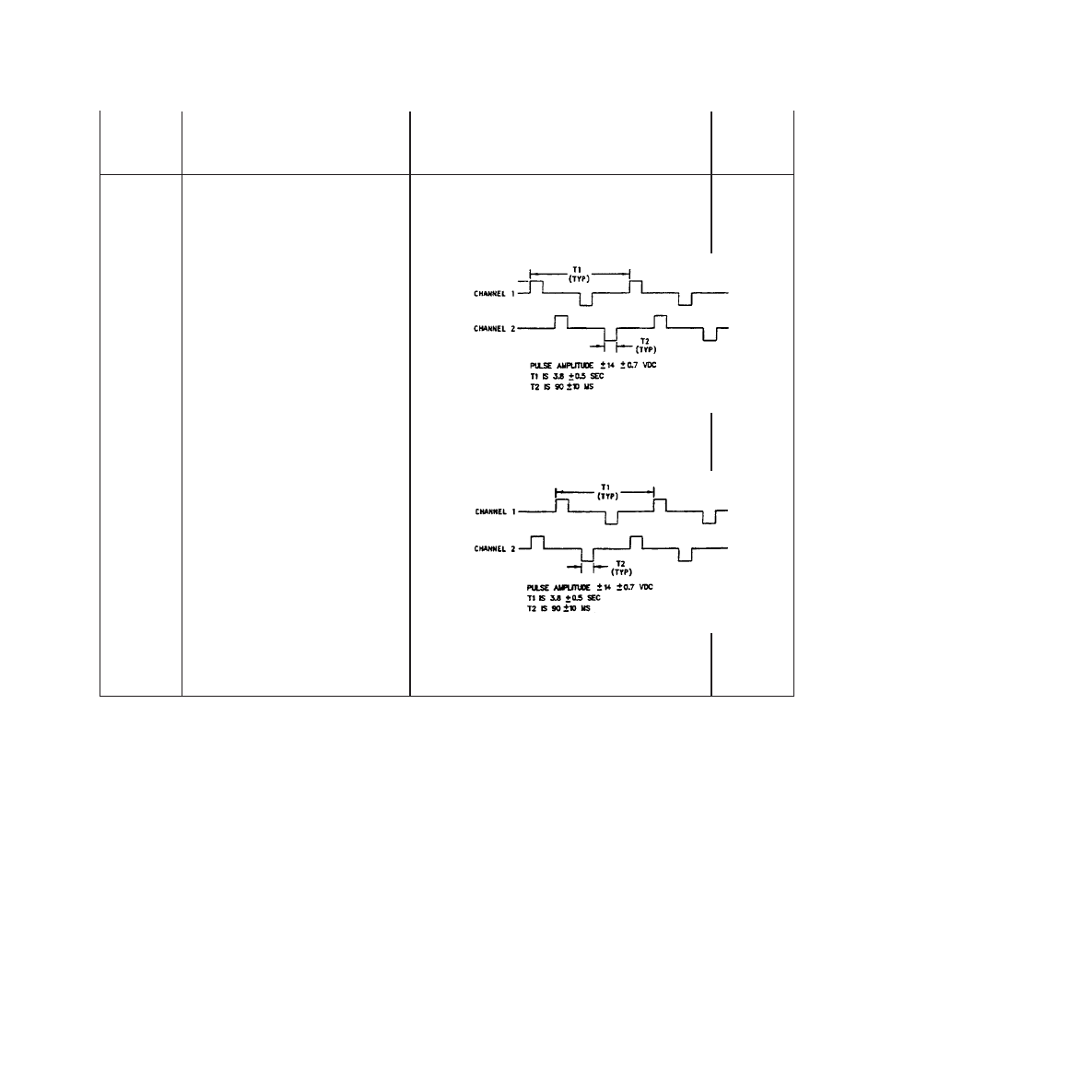
Table 5-2. Control Valve Driver Circuit Checkout - Continued
Step
Operation
Normal Indication
Trouble
Reference
8.
Set OPEN-OFF-CLOSE switch S2 to
OPEN.
CONTROL VALVE dc indicators cycle in OPEN
sequence. Valve opens. Oscilloscope display as
shown below. Disregard distortion, overshoot, and
spikes in display.
1, 2, 3.
9.
Set OPEN/CLOSE switch S2 to
CLOSE.
CONTROL VALVE dc indicators cycle in CLOSE
sequence. Valve closes. Oscilloscope display as
shown below.
1, 2, 3.
10.
Set OPEN/CLOSE switch S2 to OFF,
and disconnect dc control valve and
oscilloscope.
T.O. 33D9-17-89-1
5-11

Table 5-3. Coolant System Checkout
Step
Operation
Normal Indication
Trouble Ref
NOTE
Prior to making any hose connections with hose assemblies, inspect quick-disconnect fittings
and hoses for ease of operation and visible defects, including debris.
1.
Connect test stand to test bench
with two 25-79314-1 hoses; test
stand COOLANT IN to
COOLANT OUT and test stand
COOLANT OUT to COOLANT
IN.
2.
Plug test stand power cable into
ac POWER receptacle (Figure
4-1, 7) on test bench, and set
test stand power switch to on.
3.
Close COOLANT RETURN
valve by turning fully clockwise.
4.
Set COOLANT HEATER
CONTROL switch OFF, turn
CB1 ON, and set COOLANT
PUMP switch S1 ON.
COOLANT PUMP indicators come on.
1.
NOTE
Allow test equipment to warm up for 10 minutes prior to testing.
5.
Open COOLANT SUPPLY
valve about one turn.
T.O. 33D9-17-89-1
5-12
Change 3
Table 5-3. Coolant System Checkout - Continued
Step
Operation
Normal Indication
Trouble Ref
Flow meters are normally not damaged by reasonable excess in fluid velocity or hydraulic shock,
provided it is full of fluid. Excessive overspeed of a dry transducer may cause damage to test
bench flow meter.
NOTE
•
Momentary fluctuation of indicator meter is normal, provided above caution is observed.
•
On test stand coolant flow rotameter gauge, read scale opposite bottom of flare on moving
indicator.
6.
Very slowly turn COOLANT
RETURN valve counterclock-
wise to attain flow rate of about
1 pound per minute. Wait 1
minute to be sure all air is
forced from coolant lines.
COOLANT RETURN FLOW indication
increases to 1 pound per minute and pump can
be heard running.
1.
7.
Open COOLANT SUPPLY
valve.
T.O. 33D9-17-89-1
Change 3
5-12.1/(5-12.2 blank)


Table 5-3. Coolant System Checkout - Continued
Step
Operation
Normal Indication
Trouble Ref
8.
Adjust COOLANT RETURN
valve for a minimum of 5
pounds per minute flow and a
minimum of 14 (±3) psig on
COOLANT SUPPLY
PRESSURE meter on test bench.
A minimum of 5 pounds per minute flow and a
minimum of 14 (±3) psig indicated on test stand
meters.
2.
NOTE
If MR1000 type flow meter is installed in test bench, meter will display reading to the thou-
sandths place (three decimal places). Reading shall be rounded to the hundredths place (two
decimal places).
9.
Adjust test bench valves for test
stand indications of 1.0 (±0.2),
3.0 (±0.2), and 5.0 (±0.2)
pounds per minute coolant flow.
Test bench COOLANT RETURN FLOW meter
indicates within 0.45 pound per minute of each
test stand indication.
5.
NOTE
COOLANT RETURN valve may require slight opening to attain required pressure, but do not
exceed 0.5 pound per minute on test stand flow gauge.
10.
Close COOLANT RETURN
valve and adjust COOLANT
SUPPLY valve for test stand
pressure indications of 5 (±0.5),
10 (±0.5), and 15 (±0.5) psig.
Test bench COOLANT SUPPLY PRESSURE
meter M7 indicates within 0.5 psig of each test
stand indication.
4.
Test bench COOLANT RETURN PRESSURE
meter M4 indicates within 0.5 psig of each test
stand indication.
3.
11.
Adjust test bench coolant control
valves for four to 5 pounds per
minute flow at not less than 10
psig as indicated by test stand.
After two-minute wait for
stabilization, read test stand
temperature.
COOLANT SUPPLY TEMPERATURE meter
M6 indicates within 0.4 °F of test stand tempera-
ture.
7.
COOLANT RETURN TEMPERATURE meter
M3 indicates within 0.4 °F of test stand tempera-
ture.
6.
T.O. 33D9-17-89-1
5-13

Table 5-3. Coolant System Checkout - Continued
Step
Operation
Normal Indication
Trouble Ref
11. - Cont
NOTE
Prior to next step, COOLANT SUPPLY TEMPERATURE must indicate less than 80 °F. If
necessary, turn off COOLANT PUMP switch S1. Drain and refill coolant tank with cool
distilled water to within two to four inches from top. Turn on S1.
12.
Adjust flow for 2 to 3 pounds
per minute at not less than 10
psig as indicated on test stand.
Note that COOLANT SUPPLY
TEMPERATURE indicates less
than 80 °F. Record the
temperature.
13.
Turn on COOLANT HEATER
CONTROL switch and adjust
dial to a setting 10 °F above
temperature recorded in step 12.
COOLANT SUPPLY TEMPERATURE indicates
the dial setting (±3) degrees within 25 minutes.
8.
14.
After 25 minutes, turn off
COOLANT HEATER
CONTROL and COOLANT
PUMP switches.
15.
Close COOLANT SUPPLY and
COOLANT RETURN valves.
16.
Close AIR PURGE valve fully
clockwise.
17.
Verify facility air is connected to
test bench.
18.
Disconnect hose 25-79314-1
from test bench COOLANT
SUPPLY and connect it to AIR
PURGE SUPPLY.
19.
Disconnect other hose
25-79314-1 from test bench
COOLANT RETURN and
connect it to PURGE RETURN.
20.
Slowly open AIR PURGE valve
to purge coolant from test stand.
With valve fully open, purge for
5 minutes or until test stand
rotameter appears dry.
Air bubbles in test stand flow gauge indicate
coolant has been returned to test bench tank.
21.
Disconnect and store hose
assemblies.
T.O. 33D9-17-89-1
5-14

Table 5-4. Air Regulation Checkout
Step
Operation
Normal Indication
Trouble
Ref (Table
1.
Verify facility air is connected to test bench.
2.
Set 60 Hz POWER CB1 on.
NOTE
•
Allow test equipment to warm up for 10 minutes prior to testing.
•
Prior to making any hose connections with hose assemblies, inspect quick-disconnect fittings and
hoses for ease of operation and visible defects, including debris.
3.
Connect hose assembly 25-79314-1 from AIR PURGE
SUPPLY to test stand COOLANT IN.
4.
Connect hose assembly 25-79314-1 to test stand
COOLANT OUT, and leave other end disconnected.
5.
Slowly open AIR PURGE valve.
Test stand COOLANT PRES-
SURE gauge indicates 20 (±2)
psig.
1.
6.
Close AIR PURGE valve.
7.
Connect free end of hose assembly 25-79314-1 to test
bench PURGE RETURN to relieve pressure.
8.
Remove and store hoses.
9.
Verify the following valves are closed: COMPRESSOR
AIR RETURN, nitrogen cylinder LIQUID, nitrogen
regulator.
10.
Connect nitrogen regulator through nitrogen adapter
assembly (Figure 2-1) and hose assembly 25-79840-1 to
test stand AIR IN.
11.
Connect hose assembly 25-79314-2 to test stand AIR
OUT and to test bench COMPRESSOR AIR RETURN
AIR IN.
T.O. 33D9-17-89-1
Change 3
5-15
Table 5-4. Air Regulation Checkout - Continued
Step
Operation
Normal Indication
Trouble
Ref (Table
COMPRESSOR AIR RETURN FLOW meter shall not be allowed to exceed 2.5 CFM. Failure to
comply could result in damage to flow transducer MT4.
NOTE
•
Test stand or test bench should not exceed 225 psig. Pressure relief valve may open.
•
When reading airflow rotameter on test stand, scale opposite center of ball in indicator should be
used.
12.
Verify test stand PRESSURE gauge indicates 0.0 (±2.0)
psig. Slowly open nitrogen valve and adjust regulator for
test stand PRESSURE gauge indications of 50 (±3) and
100 (±4) psig. COMPRESSOR AIR RETURN valve may
be opened slightly for fine adjustment.
COMPRESSOR AIR PRESSURE
meter M1 indicates within 5 psig
of test stand at each pressure
setting.
2.
13.
Close nitrogen cylinder valve and bleed pressure from
COMPRESSOR AIR RETURN VALVE.
14.
Connect nitrogen source through a hose to a tee fitting
and then to test stand COOLANT IN.
15.
Connect open end of tee (step 14) through a shut off valve
to the test stand AIR IN. Close the shut off valve.
16.
On test bench, fully open COMPRESSOR AIR RETURN
valve.
17.
Adjust nitrogen source pressure to 10 to 15 psig indication
on test stand COOLANT pressure gauge. NOTE: It may
be necessary in the following step to maintain 10 to 15
psig on test stand COOLANT pressure gauge in steps 18
and 20.
18.
Slowly open valve (step 15) for 0.5 (±0.2) ACFM indica-
tion on test bench COMPRESSOR AIR RETURN FLOW
meter.
T.O. 33D9-17-89-1
5-16
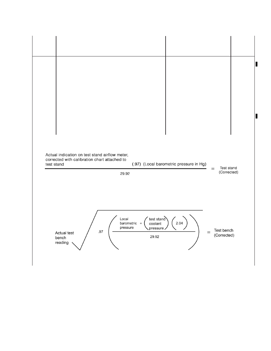
Table 5-4. Air Regulation Checkout - Continued
Step
Operation
Normal Indication
Trouble
Ref (Table
19.
(Deleted)
20.
Slowly open valve (step 15) for 1.5 (±0.2) ACFM indica-
tion on test bench COMPRESSOR AIR RETURN FLOW
meter.
21.
Record the following readings:
Test STAND Airflow
Test BENCH compressor air return flow
Test STAND coolant pressure
22.
Reduce nitrogen source pressure to 0 psig.
23.
Compute readings taken in step 21 as follows:
T.O. 33D9-17-89-1
Change 1
5-17
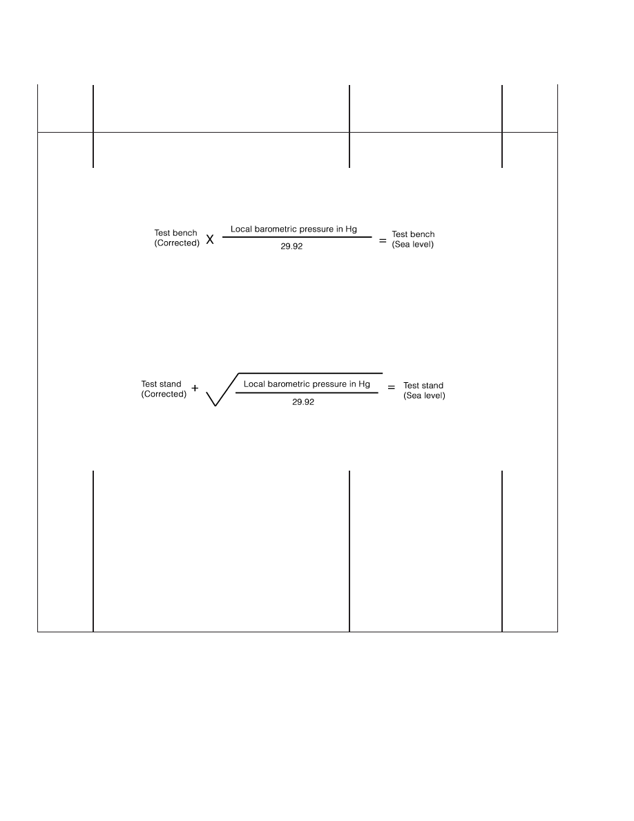
Table 5-4. Air Regulation Checkout - Continued
Step
Operation
Normal Indication
Trouble
Ref (Table
24.
Compute sea level flow rate for the test STAND and test
BENCH flow meters as follows:
25.
Test Bench (Sea level) and Test Stand (Sea level) shall
agree within (± 0.2).
Within tolerance
2.
26.
Close COMPRESSOR AIR RETURN valve.
27.
Disconnect all hoses connection nitrogen source; test
bench and test stand.
28.
Turn off nitrogen regulator, close nitrogen valve and close
COMPRESSOR AIR RETURN VALVE.
29.
Disconnect all hoses. Remove tee from hose assembly
25-79314-1 and reinstall nipple removed in step 14. Store
hose assemblies and tee.
T.O. 33D9-17-89-1
5-18
Table 5-5. Refrigeration Controls Checkout
Step
Operation
Normal Indication
Trouble Reference
•
120-Vac power is present inside cabinet when power cables are connected. Serious shock hazard
exists when panels are off. Failure to comply may result in personnel injury.
•
Do not exceed 235-psig pressure during the following tests. Relief valve may open. Failure to
comply may result in personnel injury.
NOTE
Schematics FO-2 and FO-3 illustrate plumbing and electrical refrigerant controls by nomenclature,
function, and number. These identifying numbers are nonstandard but agree with engineering data
supplied to depot and are useful here for checkout and troubleshooting.
1.
Verify CB4 is set to OFF. Disconnect
refrigerant cylinder heater cable P108
(Figure 5-1, 58) from J108 in rear of test
bench.
2.
Connect multimeter across cable
connector P108 pins X and Y. (Pin Y is
crossways, and pin X is next to Y
clockwise when viewing P108 pins.)
Multimeter indicates less than one ohm
resistance.
1.
3.
Ensure that both refrigerant cylinder
valves are closed.
4.
Remove cap (Figure 2-1, 3) from nitrogen
adapter assembly, and connect assembly
to nitrogen regulator.
Pressure is present in the hose. Faceshield and leather gloves must be used to prevent personnel injury.
5.
Close valve V7 and close the in-line
shutoff valve on the end of supply tank
hose (Figure 5-1, 77).
T.O. 33D9-17-89-1
5-19

Table 5-5. Refrigeration Controls Checkout - Continued
Step
Operation
Normal Indication
Trouble Reference
NOTE
If using self-sealing hoses, perform step 6, then proceed to step 8. If not using self-sealing hoses,
proceed to step 7.
6.
Disconnect hose (Figure 5-1, 77) from
in-line shutoff valve. Connect hose to
reclaimer and reclaim per manufacturer’s
instructions.
7.
Disconnect the in-line shutoff valve from
V7. Connect reclaimer system to in-line
shutoff valve with another refrigeration
hose. Open in-line shutoff valve and
reclaim in accordance with reclaimer
manufacturer’s instructions. Remove
in-line shutoff valve and hose from
reclaimer.
8.
Connect reclaimer system to
EVACUATION/CHARGE port on the
front of the test bench. Set 60 Hz power
CB4 to ON.
60 HZ POWER indicator on.
Table 5-6, step 1.
9.
Turn TGS-2 (PANEL POWER SWITCH)
to ON.
PANEL POWER indicator NLT-2 on.
4, 5.
10.
Set RSS-1 (REFRIGERANT
MEASURING TUBE SWITCH) selector
switch to FILL.
RSS-1 FILL indicator on.
11.
Reclaim from test bench plumbing and
fill tube in accordance with reclaimer
manufacturer’s instructions.
12.
Set TGS-2 (PANEL POWER SWITCH)
to OFF.
All indicator lights off. Switch RSS-1
repositions to OFF.
13.
Connect hose (77) to uncapped fitting on
nitrogen adapter assembly (Figure 2-1, 3).
14.
Connect hose assembly, Part No.
25-79840-1, from test stand AIR IN to
nitrogen adapter assembly.
15.
Connect hose assembly, Part No.
25-79840-2, to test stand AIR OUT, and
leave quick-disconnect end free.
16.
Apply nitrogen and vary pressure by
releasing pressure at nitrogen source;
monitor both multimeter and test stand
AIR PRESSURE gauges.
Resistance increases to greater than 1
megohm with pressure increase to 126 to
150 psig and returns to less than one ohm
when pressure falls below 126 psig.
2.
T.O. 33D9-17-89-1
5-20

Table 5-5. Refrigeration Controls Checkout - Continued
Step
Operation
Normal Indication
Trouble Reference
17.
Adjust PS-1, if required, and retest if
adjusted.
18.
Disconnect multimeter and turn off
nitrogen source. Reconnect connector
P108.
19.
Disconnect hose (Figure 5-1, 77) slowly
to bleed pressure from nitrogen adapter
assembly; replace cap (Figure 2-1, 3), and
reconnect hose to valve V7. Open in-line
shutoff valve fully and valve V7 1-1/2
turns from fully closed position.
20.
Disconnect P105 from J105 located on
program control center (Figure 5-1, 58) in
rear of test bench, and connect shorting
plug assembly, Part No. P-304-AB (Table
2-1), into J105.
21.
Connect reclaimer system to
EVACUATE/REFRIGERANT CHARGE
outlet on front of test bench. Prepare
reclaimer to accept freon as per
manufacturer’s instructions.
22.
Set PANEL POWER switch TGS-2 to
ON.
PANEL POWER indicator NLT-2 on.
4, 5.
23.
Loosen thumbscrews on lower sight-
gauge light beam assembly (Figure 4-3,
6) and insert a piece of black paper
between sight-gauge and rounded half of
light beam assembly.
24.
Set selector switch RSS-2 (Figure 4-3,
19) to CHARGE.
CHARGE indicator NLT-11 on.
4.
25.
Turn on MEASURING TUBE HEATER
switch TGS-4.
MEASURING TUBE HEATER indicator
NLT-4 may flash on momentarily when
TGS-4 is turned on.
26.
Momentarily set REFRIGERANT
MEASURING TUBE switch RSS-1 to
CHARGE, and then turn off
MEASURING TUBE HEATER switch
TGS-4.
REFRIGERANT MEASURING TUBE C
indicator NLT-6 comes on and stays on.
4, 14.
27.
Reclaim in accordance with reclaimer
manufacturer’s instructions, ensure refrig-
erant pressure gauge on test bench has
registered zero. Remove reclaimer hose
from EVACUATE/REFRIGERANT
CHARGE outlet.
T.O. 33D9-17-89-1
5-21
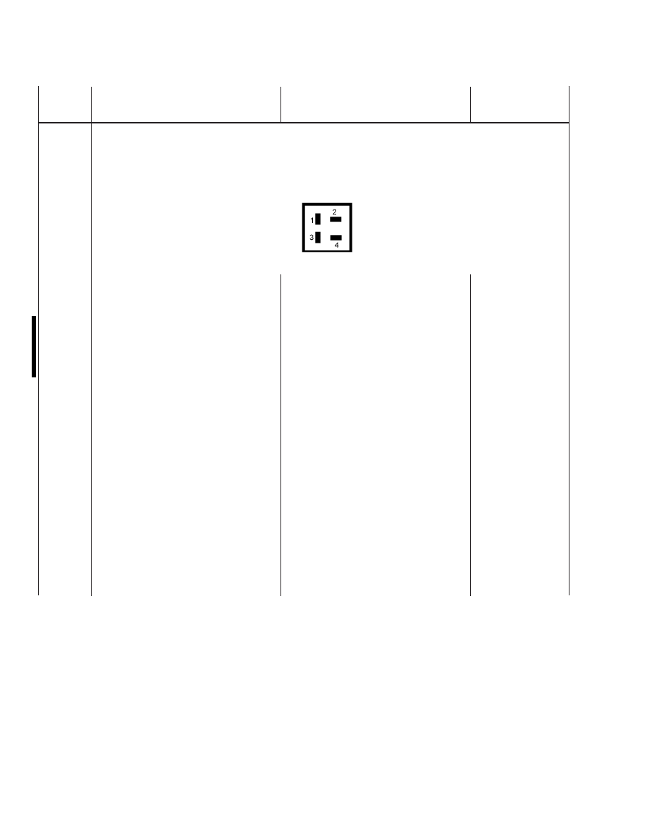
Table 5-5. Refrigeration Controls Checkout - Continued
Step
Operation
Normal Indication
Trouble Reference
NOTE
Pins are numbered as follows when viewing P105 contacts:
28.
Connect multimeter across P105 pins 1
and 2.
Multimeter indicates greater than 1
megohm resistance.
3.
29.
Resistance decreases to less than one ohm
when pressure increases to 145 to 160
psig, and returns to greater than 1
megohm when pressure decreases to 145
psig minimum.
30.
Apply nitrogen and vary pressure to test
operation of pressure switch. Observe
both test stand pressure gauge and
multimeter.
Resistance decreases to less than one ohm
when pressure increases to 100 to 122
psig, and returns to greater than 1
megohm when pressure decreases to 100
psig minimum.
3.
31.
Adjust nitrogen pressure for test stand
indication of 125 psig.
Test bench REFRIGERANT PRESSURE
gauge PI-2 indicates 125 (±5) psig.
9.
32.
Turn off nitrogen source and relieve
pressure by opening purge V5 on test
bench. Disconnect test stand.
33.
Turn off PANEL POWER switch TGS-2
and remove shorting plug, Part No.
P-304-AB, and reconnect P105 into J105.
Remove black paper from between lower
sight-gauge light beam assembly.
T.O. 33D9-17-89-1
5-22
Change 1
Table 5-5. Refrigeration Controls Checkout - Continued
Step
Operation
Normal Indication
Trouble Reference
34.
Set refrigerant controls on test bench as
follows:
NOTE
Zero (center dot) both micron gauges on test stand and test bench before proceeding to step 34a.
a. PANEL POWER switch TGS-2... on
b. PURGE VALVE V5... close
c. GAS BALLAST VALVE... close
Use two wrenches when loosening or tightening fittings to avoid stressing plumbing system. Failure to
comply may cause equipment damage.
35.
Remove cap (Figure 5-1, 67) from fitting
between solenoid valves V8 (65) and V9
(63).
36.
Connect test stand vacuum gauge trans-
ducer to fitting, connect test stand elec-
trical power connector, turn on test stand
switch, and allow a 10-minute warm-up
period.
37.
Set VACUUM PUMP switch TGS-1 to
ON.
VACUUM PUMP indicator NLT-1 on,
pump operates.
4, 6.
38.
Set selector switch RSS-2 to PUMP
TEST.
PUMP TEST indicator NLT-8 on.
4.
REFRIGERANT VACUUM manometer
indicates a vacuum.
7.
NOTE
•
If 100 microns or less cannot be attained, slowly close GAS BALLAST valve and then slightly
open GAS BALLAST valve.
•
GAS BALLAST valve should be open to prevent condensation buildup inside pump. Minimize
knocking by partially closing valve.
39.
Open GAS BALLAST valve V17 about
two turns to achieve steady state opera-
tion. Minimize knocking by adjusting
clockwise or counterclockwise as appli-
cable.
Test stand VACUUM gauge indicates 100
microns or less within 5 minutes.
7, 13.
T.O. 33D9-17-89-1
5-23
Table 5-5. Refrigeration Controls Checkout - Continued
Step
Operation
Normal Indication
Trouble Reference
40.
Allow time for stabilization.
VACUUM meter M-4 (57) indicates
within approximately 25 microns of test
stand VACUUM gauge within 30
minutes.
8.
41.
Turn test stand power switch off and
disconnect test stand electrical power
connector.
Use two wrenches when loosening or tightening fittings to avoid stressing plumbing system. Failure to
comply may cause equipment damage.
42.
Set TGS-1 VACUUM PUMP switch OFF,
remove test stand vacuum gauge trans-
ducer from test bench fitting, and reinstall
cap (67) on fitting.
43.
Set VACUUM PUMP switch TGS-1 on.
VACUUM meter M-4 (57) indicates 100
microns or less within 5 minutes.
7, 13.
Mercury height is about equal in both
legs of manometer and are opposite zero
on scale.
10.
44.
Set VACUUM PUMP switch to OFF.
45.
Connect reclaimer system to valve V13
(52) and set cylinder heater switch TGS-3
to ON.
46.
Position CYLINDER HEATER to ON.
NOTE
Loosen two thumbscrews on photo detector assembly sight-glass to ensure assembly moves freely.
47.
Using scale in back of refrigerant sight
tube, position photo detector scanners so
pointers are 11.25 inches apart. Tighten
thumbscrew firmly against rod.
T.O. 33D9-17-89-1
5-24

Table 5-5. Refrigeration Controls Checkout - Continued
Step
Operation
Normal Indication
Trouble Reference
NOTE
Perform steps 48 through 60 only if scanner units have been replaced or if faulty scanner is
suspected.
48.
Open valves V6 (82), V7 (78) and V13
(52) 1-1/2 turns from closed position.
Open LIQUID valve on refrigerant
cylinder. Ensure in-line valve is fully
open.
NOTE
As measuring tube fills, valve V13 will vent freon. Reclaimer must be operated to capture escaping
vapor. Periodically, valve V13 must be fully closed to assess refrigerant level in tube. If level no
longer rises and has not reached PD-1, reset RSS-1 to fill and reopen valve V13 as required to fill
tube.
49.
Momentarily set REFRIGERANT
MEASURING TUBE selector switch
RSS-1 to FILL.
Refrigerant rises in sight glass to photo
detector. REFRIGERANT F indicator ON
while measuring tube is filling.
11, 12.
50.
When refrigerant liquid level reaches
upper level sensor PD-1 on measuring
tube shut valve V13 and shut down
reclaimer system.
RSS-1 FILL light extinguishes and freon
level stops rising at PD-1.
51.
Turn TGS-2 (PANEL POWER SWITCH)
to OFF.
52.
Inside cabinet, disconnect P104 (Figure
5-1, 56) on top of control panel. Push
cable through opening to front of cabinet
and plug it into SKAN-A-MATIC tester.
53.
Remove controller PEC-1 (56) from J102
on top of control panel and plug it into
SKAN-A-MATIC tester.
54.
Plug tester into J3 and turn on both tester
switch and CB1.
55.
Slide upper photo detector scanner to
location above refrigerant level in sight
glass.
SKAN-A-MATIC tester VAPOR indicator
comes on.
Faulty controller
PEC-1 or detector
PD-1; replace faulty
component.
56.
Slide scanner to location below refrig-
erant level.
SKAN-A-MATIC tester LIQUID indicator
comes on.
Faulty PEC-1 or
PD-1; replace faulty
component.
T.O. 33D9-17-89-1
5-25

Table 5-5. Refrigeration Controls Checkout - Continued
Step
Operation
Normal Indication
Trouble Reference
57.
Turn off SKAN-A-MATIC tester; reinstall
PEC-1 and reconnect P104 to top of
control panel.
58.
Repeat steps 50 through 54 with lower
photo detector scanner P103 and
controller PEC-3 (55) from J101.
Faulty PEC-3 or
PD-3; replace
component.
59.
Turn off SKAN-A-MATIC tester; reinstall
PEC-3 and reconnect P103 to top of
control panel.
60.
Turn off CB1.
61.
Turn TGS-2 (PANEL POWER SWITCH)
to ON.
NOTE
If steps 48 through 60 were performed, omit steps 62 through 65.
62.
Using scale in back of refrigerant sight
tube, position photo detector scanners so
pointers are 11.25 inches apart. Tighten
thumbscrew firmly against rod.
Photo detector assembly should slide
freely on sight-gauge.
63.
Open valve V6 (82), V7 (78), and V13
(52) 1-1/2 turns from closed position.
Open LIQUID valve on refrigerant
cylinder.
Liquid eye and cylinder pressure gauge
indicate refrigerant supply.
NOTE
As measuring tube fills, valve V13 will vent freon. Reclaimer must be operated to capture escaping
vapor. Periodically, valve V13 must be fully closed to assess refrigerant level in tube. If level no
longer rises and has not reached PD-1, reset RSS-1 and reopen valve V13, as required, to fill tube.
64.
When CYLINDER HEATER light goes
out, momentarily set REFRIGERANT
MEASURING TUBE selector switch
RSS-1 to FILL.
Refrigerant rises in sight glass to level of
upper photo detector. REFRIGERANT F
indicator ON while measuring tube is
filling.
11, 12.
65.
When refrigerant liquid level reaches
upper level sensor PD-1 on measuring
tube, shut valve V13 and shut down
reclaimer system.
RSS-1 FILL light extinguishes and freon
level stops rising at PD-1.
66.
Set MEASURE TUBE HEATER switch
TGS-4 to ON. Set CYLINDER HEATER
to OFF.
MEASURING TUBE HEATER indicator
comes on.
14.
T.O. 33D9-17-89-1
5-26
Table 5-5. Refrigeration Controls Checkout - Continued
Step
Operation
Normal Indication
Trouble Reference
67.
Using vacuum bottle, connect self-sealing
refrigerant hose to test bench
EVACUATE/REFRIGERANT CHARGE
and vacuum bottle liquid valve and open
valve.
68.
Set selector switch RSS-2 to EVACUATE
and set vacuum pump switch TGS-1 to
ON. Wait until vacuum is less than 300
microns. Adjust GAS BALLAST valve as
necessary to obtain vacuum.
EVACUATE indicator NLT-9 comes on.
Pressure stabilizes at less than 300
microns.
13.
69.
Verify that pointer of upper photo
detector scanner is even with top of
refrigerant column in sight tube glass. If
required, reposition scanners without
changing space between them.
NOTE
Verify MEASURING TUBE HEATER indicator extinguishes before proceeding.
70.
Set selector switch RSS-2 to CHARGE.
CHARGE indicator NLT-11 on.
71.
Set TGS-1 VACUUM PUMP switch to
OFF.
72.
Momentarily set REFRIGERANT
MEASURING TUBE switch to
CHARGE.
REFRIGERANT MEASURING TUBE C
indicator comes on during charge. Refrig-
erant level in sight glass drops to lower
photo detector scanner within 45 to 60
seconds and stops.
4, 13, 15.
73.
When refrigerant level in measuring tube
drops to lower photo detector PD-3 on
measuring tube and RSS-1 C indicator
extinguishes, close LIQUID valve on
vacuum bottle.
Failure to set REFRIGERANT MEASURING TUBE HEATER switch to OFF when measuring tube is
not in filled condition will overheat and damage measuring tube assembly.
74.
Set REFRIGERANT MEASURING
TUBE HEATER switch to OFF.
T.O. 33D9-17-89-1
5-27
Table 5-5. Refrigeration Controls Checkout - Continued
Step
Operation
Normal Indication
Trouble Reference
75.
Set CYLINDER HEATER, PANEL
POWER, 60 HZ POWER switches CB1
and CB4 to OFF and close LIQUID valve
on refrigerant cylinder.
76.
Close valve V13, remove reclaimer
system, and recap valve V13.
Table 5-6. Power Troubleshooting
Trouble
Probable Cause
Remedy
120/208 volts of power is present inside test bench. Serious shock hazard exists when panels are removed.
Failure to comply could cause personnel injury.
1.
Indicators DS1, DS2,
DS9 through DS15 fail
to come on.
1.
Internal failure of indi-
cator assembly, unless
multiple failure.
a.
Turn off power and disconnect both
power cables.
b.
Unsolder indicator leads, loosen nut
behind panel, and remove front knurled
nut and indicator.
c.
Install new indicator.
2.
Wiring or switch
failure.
a.
Check continuity per FO-4 with power
disconnected. Replace switch or repair
wiring as required.
3.
Input power filter
failure.
a.
With power disconnected, remove
protective cover from filter (Figure 5-1,
2 and 3).
b.
Apply power and check for 120 Vac
between neutral and each phase.
c.
Disconnect power and replace filter if
required.
d.
Repeat step b if filter was replaced.
e.
Disconnect power and reinstall cover.
2.
Missing or erratic phase
A, B or C as measured
on J1 or indicated on
400 Hz meters.
1.
PHASE MONITOR
switch S4 or related
wiring.
a.
Check continuity per FO-4 with power
connected. Replace S4 or repair wiring
as required.
T.O. 33D9-17-89-1
5-28

Table 5-6. Power Troubleshooting - Continued
Trouble
Probable Cause
Remedy
2. -
Cont
2.
VOLTAGE CONTROL
variable transformer T1.
a.
With power disconnected, test each
transformer (7) section for control using
multimeter across terminals 3, 4, and 3,
5.
b.
If a transformer section continuity is
open or erratic because of wear, replace
transformer.
c.
If S4 and T1 are good, isolate wiring
fault to J1 or panel meter and repair as
required.
3.
400 Hz POWER meters
faulty or out of
adjustment.
1.
VOLTAGE M9 or
FREQUENCY M8
meter.
a.
Remove window from front of meter by
raising edge with small screwdriver and
sliding out. Adjust screw in upper right-
hand corner. Slide window back in
place.
b.
If adjustment is not effective, replace
meter. See Paragraph 5.4.3.
2.
AMPERAGE
meter/transducer
M10/T2.
a.
Adjust screw on current transformer T2
transducer (19).
b.
If adjustment is not effective, replace
meter M10 and transducer T2.
4.
Power supply module
PS1 or PS2 out of
tolerance.
1.
Complete absence of
output voltage on both
PS1 and PS2 indicates
wiring or CB3 fault.
a.
Disconnect power and check continuity.
Repair wiring or replace CB3 as
required.
2.
Output voltage of PS1
or PS2 present but out
of adjustment.
a.
With power applied, adjust the appro-
priate pod on PS2 for its proper voltage.
Adjust pod A for +5.3 (±0.02) Vdc, pod
B for +15.0 (±0.1) Vdc, and for pod C
for -15.0 (±0.1). Adjust the pod on the
bottom of PS1 for +12.0 (±0.1) Vdc.
b.
If adjustment is not effective, turn off
all power and replace power supply
module.
T.O. 33D9-17-89-1
5-29
Table 5-7. Control Valve Driver Circuit Troubleshooting
Trouble
Probable Cause
Remedy
120/208 volts of power is present inside test bench. Serious shock hazard exists when panels are
removed. Failure to comply could result in personnel injury.
CONTROL VALVE switch S3 must be set correctly before connecting control valve and operating
OPEN/CLOSE switch S2. Damage to valve and test bench will occur.
1.
LED indicators not
coming on when
driving circuits
operate.
1.
Individual LED
failure indicates faulty
LED, wiring or
driving signal
a.
Turn off all power and replace
printed circuit board in electronic
enclosure (Figure 5-1, 20). Fault
isolate LEDs, wiring, and
switches S2 and S3 meter. Repair
as required.
b.
If LED replacement is required,
tag wires and unsolder. Remove
nut and lockwasher from rear and
pull LED from front. Install new
LED using care to solder wires to
correct pins.
2.
Waveforms incorrect
during checkout.
1.
Driving circuits on
printed circuit board
failed.
a.
With power applied, adjust the
appropriate pod on PS2 for its
proper voltage. Adjust pod A for
5 Vdc reading, pod B for +15
Vdc reading, and pod C for -15
Vdc reading; adjust the pod on
the bottom of PS1 for the proper
12 Vdc reading.
3.
LEDs and waveforms
okay but control valve
not operating.
1.
Faulty control valve
or wiring.
a.
Try different control valve and
fault isolate wiring as applicable.
T.O. 33D9-17-89-1
5-30
Table 5-8. Coolant System Troubleshooting
Trouble
Probable Cause
Remedy
NOTE
Refer to component replacement procedures for tubing fittings and for digital panel meters.
1.
COOLANT
PUMP indicators
fail to come on or
coolant pump fails
to run.
1.
Indicator assembly
failure unless both
are out.
a.
Turn off CB1 and replace indicator per power
troubleshooting table.
b.
Fault isolate wiring and COOLANT PUMP
switch S1 per FO-4.
2.
COOLANT
PUMP switch if
both indicators are
out and pump is
not running.
a.
Fault isolate wiring and S1.
3.
Coolant pump if
indicators are on
but pump is not
running.
a.
Turn off CB1, drain coolant tank, and replace
coolant pump and motor assembly (Figure 5-1,
29).
2.
Coolant flow and
pressure checkout
failure.
1.
Coolant filter
element clogged.
a.
Turn off pump, drain tank, disconnect ringnut,
and lower part of filter housing (30), and
remove filter element.
b.
Examine element and housing. Clean out filter
housing, and install new element if required.
2.
Valves V2 (41),
V3 (42) or trans-
ducers MT5 (31),
RT2 (35) clogged.
a.
Disconnect and examine for obstruction.
3.
Coolant pump
dogged or worn.
a.
Remove pump, and replace or clean as
required.
T.O. 33D9-17-89-1
5-31

Table 5-8. Coolant System Troubleshooting - Continued
Trouble
Probable Cause
Remedy
3.
COOLANT
RETURN
PRESSURE meter
M4 checkout fails.
1.
Meter M4 out of
adjustment.
a.
Remove window from front of meter by
raising end with small screwdriver and sliding
out.
b.
If meter does not indicate within 0.0 (±0.5)
psig, adjust lower screw in right end of meter.
c.
If meter does not indicate within 15.0 (±0.5)
psig, adjust upper screw in right end of meter.
d.
Reinstall window.
2.
Meter M4 or
transducer MT2
faulty.
a.
Turn off CB1, and replace M4 or MT2 (36) as
required.
4.
COOLANT
SUPPLY
PRESSURE meter
M7 checkout fails.
1.
Meter M7 out of
adjustment.
a.
Same as remedy for COOLANT RETURN
PRESSURE meter M4.
2.
Meter M7 or
transducer MT3
faulty.
a.
Turn off CB1, and replace M7 or MT3 (12) as
required.
NOTE
For PRI-3 type meter use steps 5 (1a thru d) and for MR1000 type meter use steps 5 (1e thru h).
5.
COOLANT
RETURN FLOW
meter M5
checkout fails.
1.
Meter M5, linear-
izer A2 or trans-
ducer MT5 faulty
or out of calibra-
tion.
a.
Turn off CB1, and remove M5, A2 (37) and
MT5 (31). Do not adjust units or remove tags.
Install replacement M5, A2, and MT5 as a
calibrated set having matching tag numbers.
Leave tags attached.
b.
Remove window from front of meter by
raising end with small screwdriver and sliding
out.
c.
Set internal right-hand switches No. 7, 8, 9, 10
to up, down, up, down positions, respectively.
Do not disturb left-hand switches, right-hand
switches No. 1 through 6, or adjustment
screws.
d.
Reinstall window.
e.
Turn off CB1, and remove M5, A2(37) and
MT5(31). Do not adjust units or remove tags.
Install replacement M5, A2, and MT5 as a
calibrated set having matching tag numbers.
Leave tags attached.
T.O. 33D9-17-89-1
5-32
Table 5-8. Coolant System Troubleshooting - Continued
Trouble
Probable Cause
Remedy
5. - Cont
f.
Refer to FO-4 during wiring connections.
Connected wire marked M5(5) to pin 5 on
meter. Connected wire marked M5(-) to pin 8
on meter.
g.
Remove two wires marked M5(15) from
connector plug and install on pin 11 of meter.
h.
Remove two wires marked M5(5) from
connector plug and install on pin 12 of meter.
6.
COOLANT
RETURN
TEMPERATURE
meter M3
checkout fails.
1.
Meter M3 or
sensor RT2 faulty
or out of calibra-
tion.
a.
Turn off CB1, and remove M3 and RT2. (35).
Install replacement M3 and RT2 as a cali-
brated set having matching serial numbers.
7.
COOLANT
SUPPLY
TEMPERATURE
meter M6
checkout fails.
1.
Meter M6 or
transducer RT3
faulty or out of
calibration.
a.
Turn off CB1, and remove M6 and RT3. (13).
Install replacement M6 and RT3 as a cali-
brated set having matching serial numbers.
8.
COOLANT
HEATER
CONTROL panel
A1 checkout fails.
1.
Panel A1, immer-
sion heater HR1,
temperature sensor
RT1 faulty.
a.
Turn off COOLANT PUMP switch S1 and 60
Hz POWER CB1.
b.
Remove screws from rear cover of A1 (5) and
carefully move cover to one side.
c.
Using wiring diagram FO-4, identify and
isolate wires to HR1 (28) and RT1 (26), and
check continuity.
d.
Replace HR1 or RT1 if open-circuited.
e.
Replace A1 if HR1 and RT1 are both good.
T.O. 33D9-17-89-1
5-33
Table 5-9. Air Regulation Troubleshooting
Trouble
Probable Cause
Remedy
NOTE
Refer to component replacement procedures for tubing fittings and for digital panel meters.
1.
Pressure regulator V16
checkout failure.
1.
Regulator V16 faulty.
a.
If indicated pressure is out of
tolerance, remove and replace
(Figure 5-1, 1) V16.
b.
If indicated pressure is zero or if
regulator replacement does not
correct problem, replace valve V4
(11).
2.
COMPRESSOR AIR
RETURN PRESSURE
meter M1 checkout
failure.
1.
Meter M1 out of
adjustment.
a.
Remove window from front of
meter by raising end with small
screwdriver and sliding out.
b.
If meter does not indicate within
0.0 (±2.0) psig, adjust lower screw
in right end of meter.
c.
If meter does not indicate within
100 (±5) psig, adjust upper screw
in right end of meter.
d.
Reinstall window.
2.
Meter M1 or sensor MT1
faulty.
a.
Turn off CB1 and replace M1 or
MT1 (40) as required.
3.
COMPRESSOR AIR
RETURN FLOW meter
M2 checkout failure.
1.
Meter M2, amplifier A3
or transducer MT4 faulty.
a.
Turn off CB1, and remove M2,
A3 (34), and MT4 (39). Do not
adjust units or remove tags. Install
replacement M2, A3, and MT4 as
a calibrated set having matching
tag numbers. Leave tags attached.
T.O. 33D9-17-89-1
5-34
Table 5-10. Refrigeration Controls Troubleshooting
Trouble
Probable Cause
Remedy
•
120-Vac power is present inside test bench. Serious shock hazard exists when panels are removed.
Failure to comply could result in personnel injury.
•
Do not exceed 250-psig pressure when testing PS-1 and TS-1 and make no adjustments except as
specified. PS-1 and TS-1 are safety devices to protect equipment and personnel. Failure to comply
may result in personnel injury.
NOTE
Refer to component replacement procedures for tubing fittings.
1.
Refrigerant cylinder pres-
sure switch PS-1 or
temperature switch TS-1
open before cylinder is
heated and before pres-
sure is applied during
checkout.
1.
PS-1, TS-1 or wiring
faulty.
a.
Turn off CB4 and remove cover
from PS-1 (Figure 5-1, 74). Loosen
cover screws of electrical box and
open to expose TS-1 (75) on band
heater. Using multimeter, isolate
open circuit.
b.
If TS-1 or PS-1 is open circuited,
replace it.
c.
If neither TS-1 nor PS-1 is open,
fault isolate wiring per FO-4 and
repair as required.
2.
Pressure switch PS-1 out
of adjustment or faulty.
1.
PS-1 out of adjustment.
a.
Attempt to adjust PS-1 to open
within range of 126 to 150 psig,
using adjustment screws on PS-1
and pressure gauge on nitrogen
cylinder.
2.
If adjustment attempt is
not successful, PS-1 is
faulty.
a.
Remove and replace entire PS-1
assembly.
3.
Pressure switch PS-2 out
of adjustment or faulty.
1.
PS-2 out of adjustment.
a.
Turn off CB4 and remove cover
from PS-2 (54). Using 1/4 wrench,
turn adjusting nut on top of switch
assembly until signal indicator on
switch is fully up. Nut will turn
easily until it reaches stop; do not
force.
b.
Apply nitrogen pressure, and adjust
regulator for 160 psig indication on
test stand.
T.O. 33D9-17-89-1
5-35

Table 5-10. Refrigeration Controls Troubleshooting - Continued
Trouble
Probable Cause
Remedy
3. -
Cont
c.
Connect multimeter across
terminals of PS-2.
d.
Back off signal adjusting nut until
switch closes, as indicated on
multimeter.
e.
Change nitrogen pressure and
check that switch closes with
increasing pressure at 160 psig
maximum and switch opens with
decreasing pressure at 145 psig
minimum.
2.
PS-2 faulty.
a.
Replace PS-2.
4.
Fault neon panel indica-
tors NLT-1 thru NLT-11,
faulty switch or faulty
wiring.
1.
Internal resistor failed.
a.
Replace neon indicator assembly.
2.
Damaged wire, loose
terminals or switch
failure.
a.
Fault isolate per FO-4 and repair as
required.
5.
5 AMP FUSE indicator
on.
1.
Fuse failed.
a.
Replace fuse.
2.
Short to ground in refrig-
erant fill and charge
control circuits.
a.
With power disconnected, use sche-
matic FO-4 and multimeter to
isolate fault. Repair as required.
6.
Vacuum pump does not
run.
1.
Loss of electrical power
if VACUUM PUMP
indicator not on.
a.
Disconnect power and fault isolate
wiring and VACUUM PUMP
switch TGS-1 at J112 (58) pins 2
and 3.
2.
Vacuum pump motor
failure.
a.
Remove vacuum pump motor (70).
b.
Install replacement pump motor
and adjust belt to flex the thickness
of the belt with normal thumb pres-
sure midway between pulleys.
7.
Vacuum failure during
vacuum pump test.
1.
Solenoid valve
SOL-V/V8 not open or
SOL-P/V9 not closed or
pump is not functioning
properly if no vacuum is
indicated.
a.
Disconnect power and fault isolate
wiring and selector switch RSS-2
at J111 (58) pins 3 and 4.
b.
Check continuity of SOL-V coil at
P111 pins 3 and 4. Repair wiring
or replace SOL-V/V8 (65) as
required.
c.
Remove vacuum pump drive belt
pulley guard (72) and replace belt
if broken or slipping.
T.O. 33D9-17-89-1
5-36

Table 5-10. Refrigeration Controls Troubleshooting - Continued
Trouble
Probable Cause
Remedy
7. -
Cont
d.
Remove and replace SOL-P/V9
(63).
2.
Required vacuum
pressure cannot be
attained.
a.
Ensure tubing fittings are tight.
b.
If vacuum pump oil contamination
is suspected, drain oil. Unscrew
discharge mist eliminator tank from
pump and pour one pint super
X/Flushing High Vacuum oil into
discharge opening of pump casting.
Reinstall tank and run pump about
2 minutes. Remove tank, add 1/3
pint oil and reinstall tank.
c. Replace vacuum pump.
8.
VACUUM meter M-4
(57) not within 25
microns of test stand.
1.
VACUUM meter out of
adjustment.
a.
Turn off CB4.
b.
Remove rear cover of program
control center (58) and remove
meter retaining nuts (do not
remove wires). Slide meter out
front of panel.
c.
Turn on CB4.
d.
Turn adjustment screw on top of
meter until indication is within 25
microns of test stand indication.
e.
Turn off CB4.
f.
Reinstall meter and cover.
g.
Turn on CB4.
2.
VACUUM meter faulty.
a.
Turn off CB4 and replace meter.
9.
REFRIGERANT
PRESSURE gauge out of
calibration.
a.
Remove and replace gauge.
10.
Manometer gauge (86)
mercury columns not
about equal height at 100
microns vacuum.
1.
Manometer faulty.
a.
Remove scale from front of
manometer, and have tube sealing
mechanism ready to install. (See
Chapter 3).
b.
One person hold manometer and a
second person disconnect tube
fitting and two mounting nuts in
rear. Remove manometer from
panel, keeping U-tube upright.
T.O. 33D9-17-89-1
5-37

Table 5-10. Refrigeration Controls Troubleshooting - Continued
Trouble
Probable Cause
Remedy
10. -
Cont
c.
Remove wingnut, gauge head, and
two neoprene gaskets from
manometer.
d.
Slowly insert plunger end of
sealing mechanism into right-hand
leg of U-tube until it barely
contacts mercury.
e.
Grip threaded end of mechanism
and turn down nut until expansion
washer at plunger end makes very
snug fit in tube.
f.
Carefully install washer, coil
spring, gauge head, and wingnut on
manometer.
g.
On replacement manometer, reverse
the removal procedure, again being
careful when removing sealing
mechanism and in keeping U-tube
upright.
h.
Store tube sealing mechanism in
top drawer of test bench.
11.
Refrigerant measuring
tube will not fill.
1.
If REFRIGERANT F
indicator does not come
on, failure is electrical.
a.
Fault isolate by replacing the
following plug-in parts:
1.
PEC-1 (56) at J102 on
top of control panel
assembly (58). Refer to
checkout with
SKAN-A-MATIC tester.
2.
Relay CR-F (61) within
control panel assembly.
b.
With power off, fault isolate
REFRIGERANT MEASURING
TUBE switch RSS-1 and related
wiring.
2.
If REFRIGERANT F
indicator comes on,
failure is in refrigerant
line.
a.
Verify refrigerant is indicated in
liquid eye on cylinder and that
valves V6 (82), V7 (78), and V13
(52) are open.
T.O. 33D9-17-89-1
5-38

Table 5-10. Refrigeration Controls Troubleshooting - Continued
Trouble
Probable Cause
Remedy
11. -
Cont
b.
If measuring tube partially fills and
REFRIGERANT PRESSURE
gauge indicates operating pressure
of about 125 psig, failure is in
solenoid valve SOL-E/V12 (87).
Check continuity of solenoid at
P105 (58) pins 3 and 4. Repair
wiring, if required, or remove and
replace solenoid valve.
c.
If no refrigerant transfers to
measuring tube and no pressure
increase registers on gauge, failure
is in solenoid valve SOL-F/V11
(79). Check continuity at P109 (58)
pins 1 and 4. Repair wiring, if
required, or remove and replace
solenoid valve.
12.
Refrigerant measuring
tube overfills.
1.
Photoelectric device
failure.
a.
If upper photo detector scanner
PD-1 (Figure 4-3, 4) light beam is
visible, photoelectric controller
PEC-1 (Figure 5-1, 56) at J102.
b.
If PD-1 light beam is not visible or
if PEC-1 did not correct problem,
replace PD-1 at J104 (56) and on
sight glass.
c.
Refer to checkout with
SKAN-A-MATIC tester.
d.
Fault isolate and repair wiring.
13.
Evacuation of pressure
vessel fails.
1.
System leaks if unable to
attain required vacuum.
a.
Check hose connections and tighten
fittings if required.
2.
SOL-P/V9 not open if
vacuum occurs too
quickly.
a.
Check continuity of SOL-P/V9 (63)
at P110 (58) pins 1 and 2. Repair
wiring, if required, or remove and
replace solenoid valve.
14.
Refrigerant does not
transfer from measuring
tube when charge cycle
is attempted.
1.
If REFRIGERANT C
indicator does not come
on, failure is electrical.
a.
Verify MEASURING TUBE
HEATER indicator cycled from ON
to OFF before charge attempt and
that function selector switch is set
to CHARGE.
b.
Fault isolate by replacing the
following plug-in parts:
1.
PEC-3 at J101 (55).
2.
Relay CR-C (60).
3.
Relay CR-H (59).
T.O. 33D9-17-89-1
5-39

Table 5-10. Refrigeration Controls Troubleshooting - Continued
Trouble
Probable Cause
Remedy
14. -
Cont
c.
With power off, fault isolate
REFRIGERANT MEASURING
TUBE switch RSS-1, function
switch RSS-2, and related wiring.
d.
Disconnect a wire from each
measuring tube heater element and
check continuity through it.
Replace element if open circuited.
See Paragraph 5.4.2.
2.
If REFRIGERANT C
indicator does come on,
failure is in solenoid
valve SOL-C/V10.
a.
With power off, check continuity of
SOL-C at P109 (58) pins 1 and 3.
b.
Repair wiring, if required, or
remove and replace solenoid valve
(81).
15.
Refrigerant transfer does
not stop at lower photo
detector during charge
cycle.
1.
Photoelectric device
failure.
a.
If lower photo detector PD-3 light
beam is visible, replace photoelec-
tric controller PEC-3 at J101 (55).
b.
If light beam is not visible or if
PEC-3 did not correct problem,
replace PD-3 at J103 (55) and on
sight glass.
c.
Refer to checkout with
SKAN-A-MATIC tester.
d.
Fault isolate and repair wiring.
16.
Pressure vessel weight
incorrect after charge
test.
a.
Contact technical engineering.
17.
No evidence of refrig-
erant cylinder heating.
Blanket should feel warm
and REFRIGERANT
PRESSURE gauge indi-
cation should rise to
about 125 psig.
1.
Cylinder heater faulty.
a.
Turn off CB4, and check continuity
across plug P108 (58) pins Y and
Z. (Pin Y is crossways, and pin X
is next to Y counterclockwise when
viewing P108 pins).
b.
If open circuited, open electrical
box on heater assembly, disconnect
wires in box, unsnap, and remove
band heater.
c.
Install and assemble replacement
heater.
2.
CYLINDER HEATER
switch TGS-3 or wiring
faulty.
a.
Fault isolate TGS-3 and wiring.
Repair as required.
T.O. 33D9-17-89-1
5-40
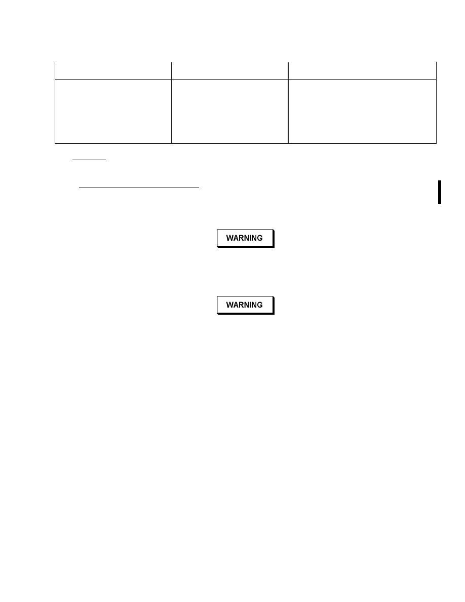
Table 5-10. Refrigeration Controls Troubleshooting - Continued
Trouble
Probable Cause
Remedy
18.
CYLINDER HEATER
indicator does not cycle
off during periods when
refrigerant valve is closed
and heater switch is on.
Cylinder is hot.
1.
Thermostat temperature
switch TS-1 not opening.
a.
Turn off CB4.
b.
Loosen cover screws and remove
cover of box to access TS-1 (75).
c.
Replace TS-1.
5.3
SERVICE.
Routine and periodic servicing is required of the coolant supply, coolant filter, refrigerant supply, and vacuum pump.
5.3.1
Coolant Supply and Filter Servicing.
It is required to replenish the coolant in the storage tank to 3 (±1) inches
from the top and to periodically remove and clean/replace the filter element. Place a suitable container under the coolant tank
petcock and drain water. Access the filter element by removing the ringnut and lower filter housing (Figure 5-1, 30). Examine
the filter element. If damaged, discard and replace with a new filter element. If undamaged, clean the filter element with an
ultrasonic cleaner (Table 2-1) as follows:
Ultrasonic cleaning detergent is toxic and hazardous. Wear approved eye and hand
protection. Failure to comply could result in personnel injury.
a.
In a clean container, mix four liters of distilled water with 100 milliliters of Micro 10 ultrasonic cleaning
concentrate detergent or equivalent. Stir to thoroughly dissolve concentrate.
Filter element and/or ultrasonic cleaner may be contaminated with sodium chromate
solution. Wear approved eye and hand protection. Failure to comply may result in personnel
injury.
b.
Wipe inside of ultrasonic cleaner with a clean, dry cloth to remove dust or impurities before use.
c.
Place filter element into ultrasonic cleaner.
d.
Pour cleaning solution into the ultrasonic cleaner until filter element is covered. Place lid on cleaner.
e.
Plug ultrasonic cleaner into a 110-volt outlet and set selector switch to ON.
f.
Allow ultrasonic cleaner to operate a minimum of 15 minutes.
g.
Set selector switch to OFF and unplug unit.
NOTE
When cleaning extremely dirty filter elements, additional cleaning may be required. Discard
filter element if not clean after second additional cleaning.
h.
If additional cleaning is required, proceed to step a.
i.
Remove filter element from ultrasonic cleaner.
j.
Add 100 milliliters of ultrasonic cleaning concentrate to original solution and stir to thoroughly dissolve
concentrate.
k.
Place filter element into ultrasonic cleaner.
l.
Repeat step d, step e, and step f.
m.
Remove filter element from ultrasonic cleaner and rinse with distilled water.
T.O. 33D9-17-89-1
Change 2
5-41

Solution in ultrasonic cleaner may be contaminated with sodium chromate solution. Wear
approved eye and hand protection. Failure to comply may result in personnel injury.
NOTE
Residual stains on the filter element do not affect the operational capability as long as the
element passes the flow checkout procedure.
n.
Empty solution from ultrasonic cleaner into a container suitable for disposal of hazardous waste.
o.
Rinse ultrasonic cleaner with distilled water empty into container suitable for disposal of hazardous waste. Dry
with a clean cloth.
5.3.2
Refrigerant Supply Service.
The refrigerant supply must be replenished if refrigerant is not visible in the liquid
eye on the cylinder when the LIQUID valve is open.
NOTE
The supply tank should be connected with a low-loss refrigerant hose which contains an
integral shutoff valve at the end connected to the tank.
a.
Close both the liquid and vapor valves on the tank.
b.
If the tank is connected with a low-loss refrigerant hose with a shutoff valve, go to step d. If the tank is not
equipped with such a hose, close valve V7.
NOTE
Venting of the refrigerant vapor contained in the hose connecting the tank to the test bench
is allowable under section 608 of the Clean Air Act. However, any nonshutoff-type
refrigerant hoses should be changed to low-loss type hoses to minimize refrigerant venting
during future tank replacements.
c.
Slowly loosen the hose connection on the tank. Allow the pressure to bleed off before disconnecting the hose.
d.
Close the shutoff valve at the end of the hose connecting the tank to the test bench.
e.
Remove and replace refrigerant supply tank.
5.3.3
Vacuum Pump Service.
Contaminated oil is the most common cause of poor performance, and the contamination
is controlled to a great extent by gas ballast operation. Avoid extended operation with the GAS BALLAST valve closed. Oil
can be visually checked by draining a small quantity into a clean container and inspecting for solid or liquid contaminants.
Periodically, and when found to be contaminated, the oil must be changed. When servicing the vacuum pump, also make the
following inspections:
a.
Remove the guard (Figure 5-1, 72) and inspect the belt for wear and adjustment. Belt should flex about the thick-
ness of belt with normal thumb pressure midway between pulleys.
b.
Turn the pump clockwise by hand. Observe no mechanical interference, but an increase in required force at angle
where discharge occurs. If required force indicates cylinder is flooded, causing a hydraulic lock, rock the pump
pulley by hand to force the oil out. The pump will flood if the vacuum break valve (SOL-B, 68) fails to open.
c.
When pump is operating, observe that oil is about midway in sight glass (71) when inlet pressure is low and that
oil level changes with large changes in vacuum indications. If there are no discernible oil level changes, oil pas-
sages within the pump may be obstructed.
5.3.3.1
Changing the Oil.
Open both drain valves (73), remove the filler plug and oil mist eliminator (69), and remove
the drive belt guard. After the oil drains, turn the pump pulley clockwise a few turns by hand to clear all oil from cylinder.
Close the drain valves. The oil capacity of the pump is 1-1/3 pints or 21-1/3 ounces. Pour about seven ounces through filler
plug hole and the remainder through the hole from which the oil mist eliminator was removed. Check that filler plug and
gasket are clean and in good condition, and reinstall plug with gasket and the oil mist eliminator. If oil was badly
contaminated, it may be necessary to flush the pump by changing the oil one or more additional times with a short operating
period between changes.
T.O. 33D9-17-89-1
5-42

5.3.3.2
Oil Mist Eliminator.
Pump back-pressure of 4 to 6 psig, as measured at the mist eliminator inlet or pump filler
plug, is an indication of clogged filter element. Pump motor heating is another indication. If mist is being discharged from mist
eliminator, the filter element or gasket may be ruptured. However, periodic replacement of the filter element greatly reduces
the probability of these failures occurring. When required, remove the top half of the mist eliminator, clean and inspect
housing, replace filter element with a new one, and reassemble using a new gasket.
5.4
COMPONENT REPLACEMENT.
The removal and installation of test bench components requires use of common hand tools and common shop skills. Special
procedures in this section apply to components with hidden fasteners and to components requiring sealing.
5.4.1
Tubing Fittings.
Before assembling tubing components, inspect all parts for damage, wear, thread condition, and
cleanliness. Reject unsatisfactory parts. Wrap male pipe threads of coolant and air fittings with Teflon tape. On refrigerant and
vacuum pipe threads, first apply high vacuum sealant, then wrap with two layers of Teflon tape, and apply sealant over the
tape. Assemble all straight thread fittings using dry lubricant or water.
5.4.2
Measuring Tube Heater Replacement.
Before installing immersion heater elements into the refrigerant
measuring tube baseplate (83), apply adhesive to the heater element threads.
5.4.3
Digital Panel Meters.
The digital type meters contain either one or two printed circuit boards which protrude out
the rear for cable connection. The two flowmeters have screw terminals and all other meters use cable connectors. All except
the flowmeters fasten to the panel by a screw-clamp arrangement accessible behind the front window. The flowmeters fasten
to the panel with mounting brackets and screws at the rear. To remove a flowmeter, first electrically disconnect it at the rear.
Then remove the bracket screw and the bracket at each end. To remove any other meter, pull the cable connector(s) off the
rear, and then on the front slide the window out by first carefully lifting one end with a small screwdriver. Loosen the mounting
screw at each end and remove the meter from the panel. Reverse the procedure to install a meter.
T.O. 33D9-17-89-1
5-43/(5-44 blank)

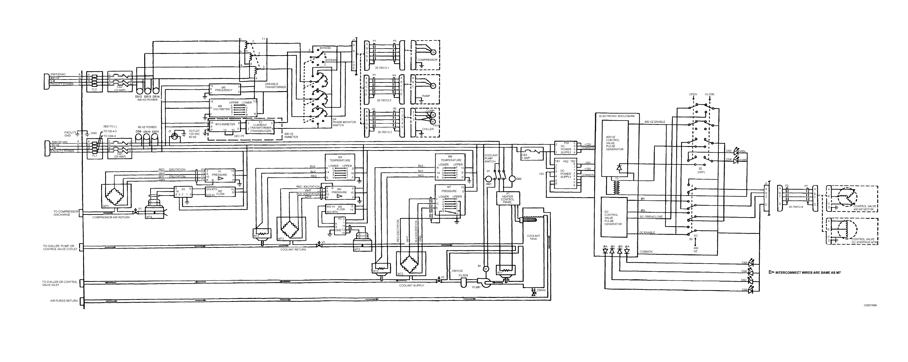
FO-1. Electrical Schematic - Left Side of Test Bench
T.O. 33D9-17-89-1
FP-1/(FP-2 blank)

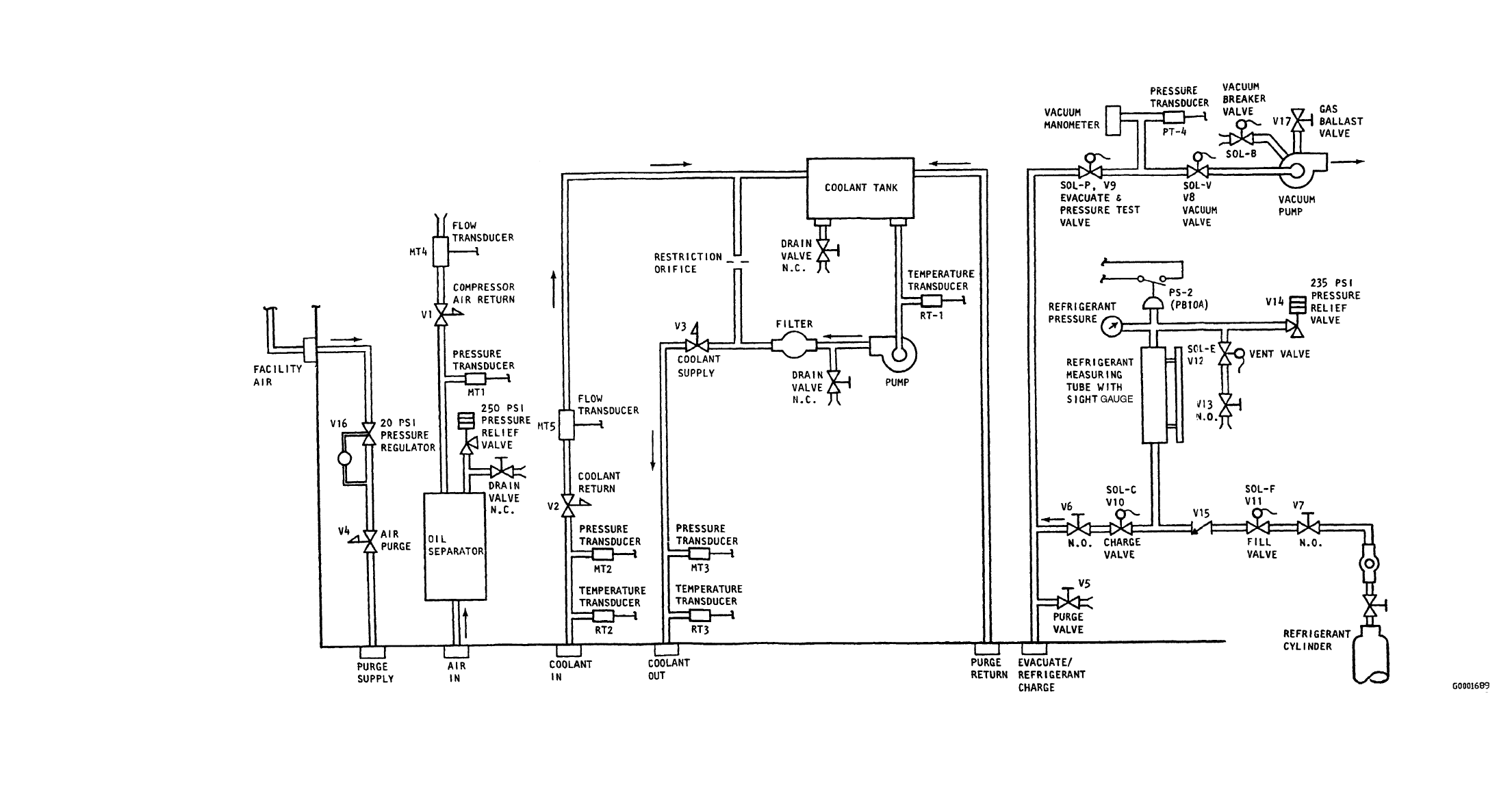
FO-2. Plumbing Schematic
T.O. 33D9-17-89-1
FP-3/(FP-4 blank)

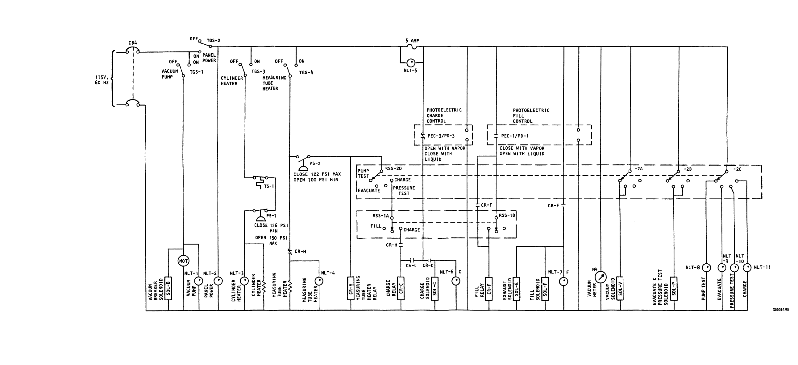
FO-3. Electrical Schematic - Right Side of Test Bench
T.O. 33D9-17-89-1
FP-5/(FP-6 blank)

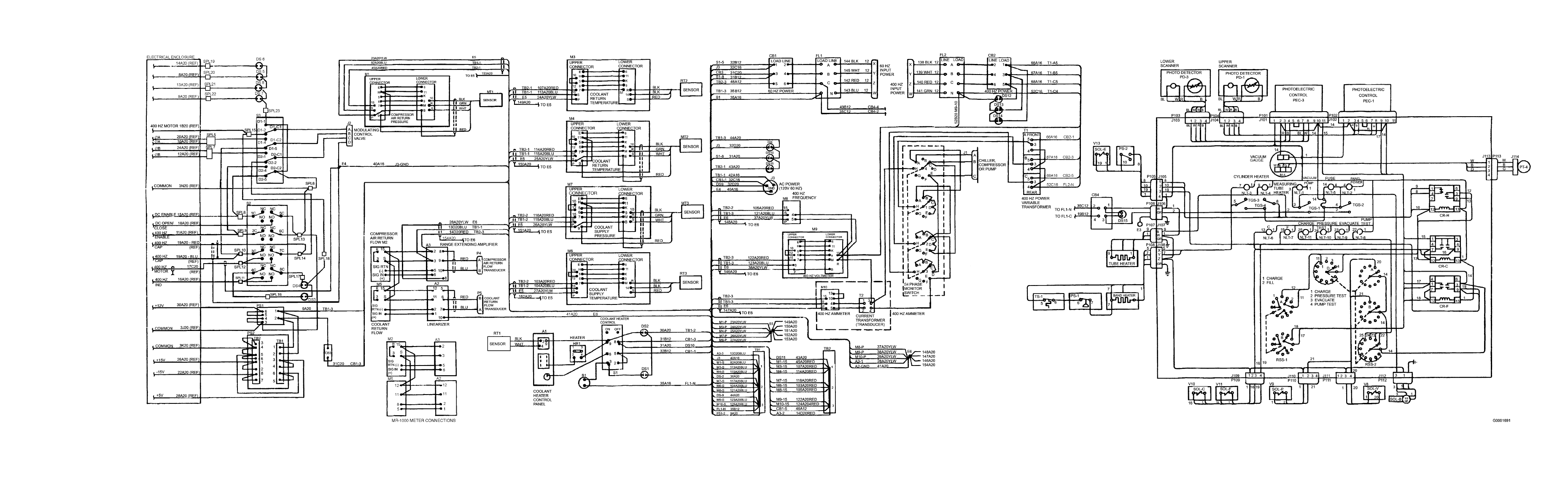
FO-4. Wiring Diagram
T.O. 33D9-17-89-1
FP-7/(FP-8 blank)

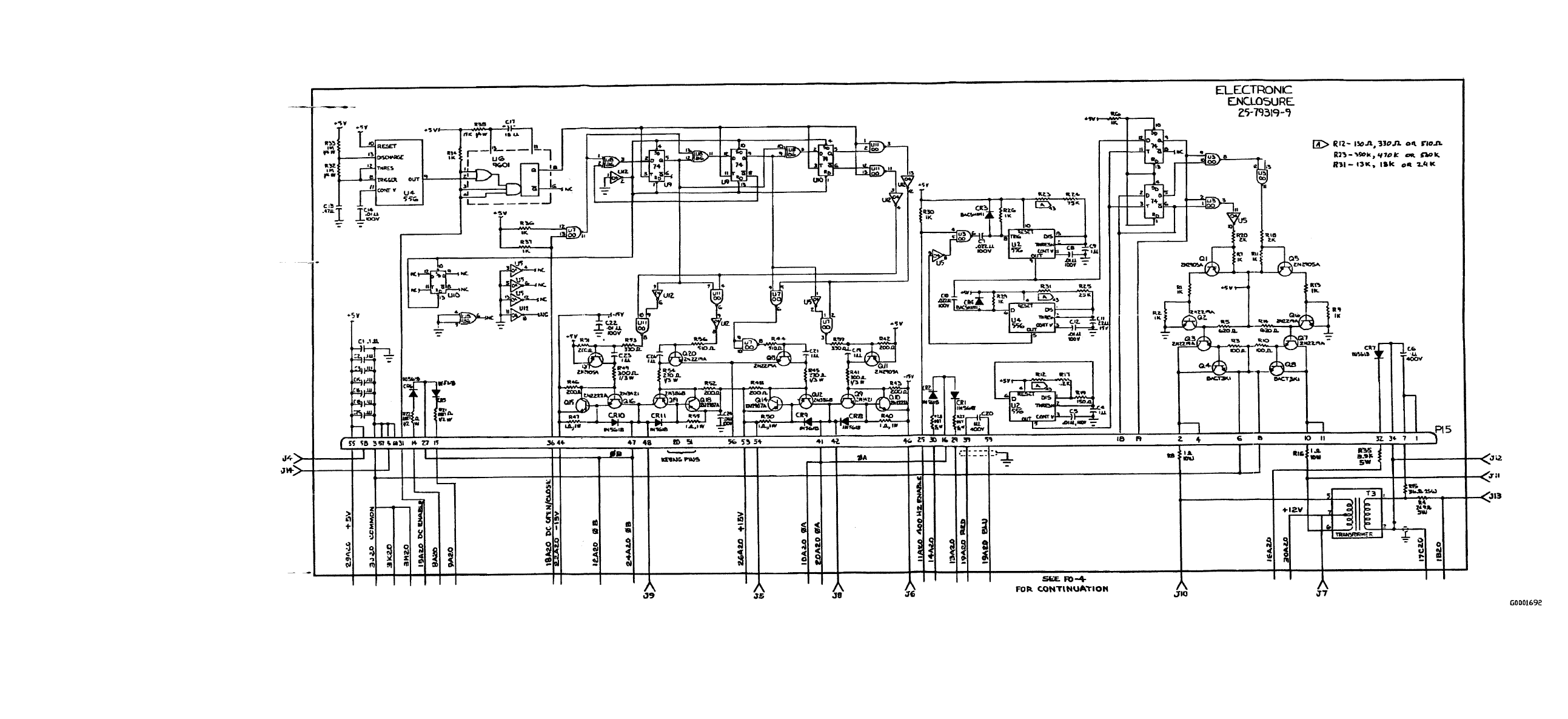
FO-5. Electronic Enclosure Schematic
T.O. 33D9-17-89-1
FP-9/(FP-10 blank)

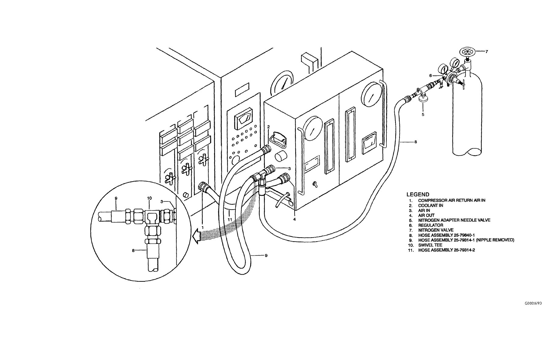
FO-6. Airflow Checkout Connections
T.O. 33D9-17-89-1
FP-11/(FP-12 blank)

Document Outline
- TITLE
- LEP
- TABLE OF CONTENTS
- LIST OF ILLUSTRATIONS
- LIST OF TABLES
- SAFETY SUMMARY
- CHAPTER 1
- CHAPTER 2
- CHAPTER 3
- CHAPTER 4
- CHAPTER 5
- FOLDOUTS
Wyszukiwarka
Podobne podstrony:
OOBE w Minute - Nowa Technika, Oobe
Martial Arts Us Military Boxing Trainers Manual
OOBE w minutę Nowa technika artykuł z forum
(E Book Martial Arts) Us Military Boxing Trainers Manual 2
D 1 LC Technical Manual
Hitman A Technical Manual For Independent Contractors
mmc sd memory card driver technical manual
SAFT technical manual
warunki techniczne 09 2008
BIG MIKES Redknapp manual 2008
OOBE w minutę Nowa technika artykuł z forum
XK3118T1 Technical Manual
XK3118T1 Technical Manual
Manual Acer TravelMate 2430 US EN
2008-probny-praktyka-teleinformatyk-wlasny, Technik Informatyk, materialy egzamin teoretyczny
Rys tech - Sprawko - Stopy żelaza(2), Studia WNOŻ SGGW 2008-2013, Inżynierskie, Semestr 1, Rysunek t
003 Warunki techniczne jakim powinny odpowiadac budynki i ich usytuowanie stan prawny na 15 grudnia
2008-probny-praktyka-teleinformatyk-wlasny-klucz, Technik Informatyk, materialy egzamin teoretyczny
więcej podobnych podstron