Audi A6
Fitting Locations
No. 802 / 1
Edition 08.2008
Fuses
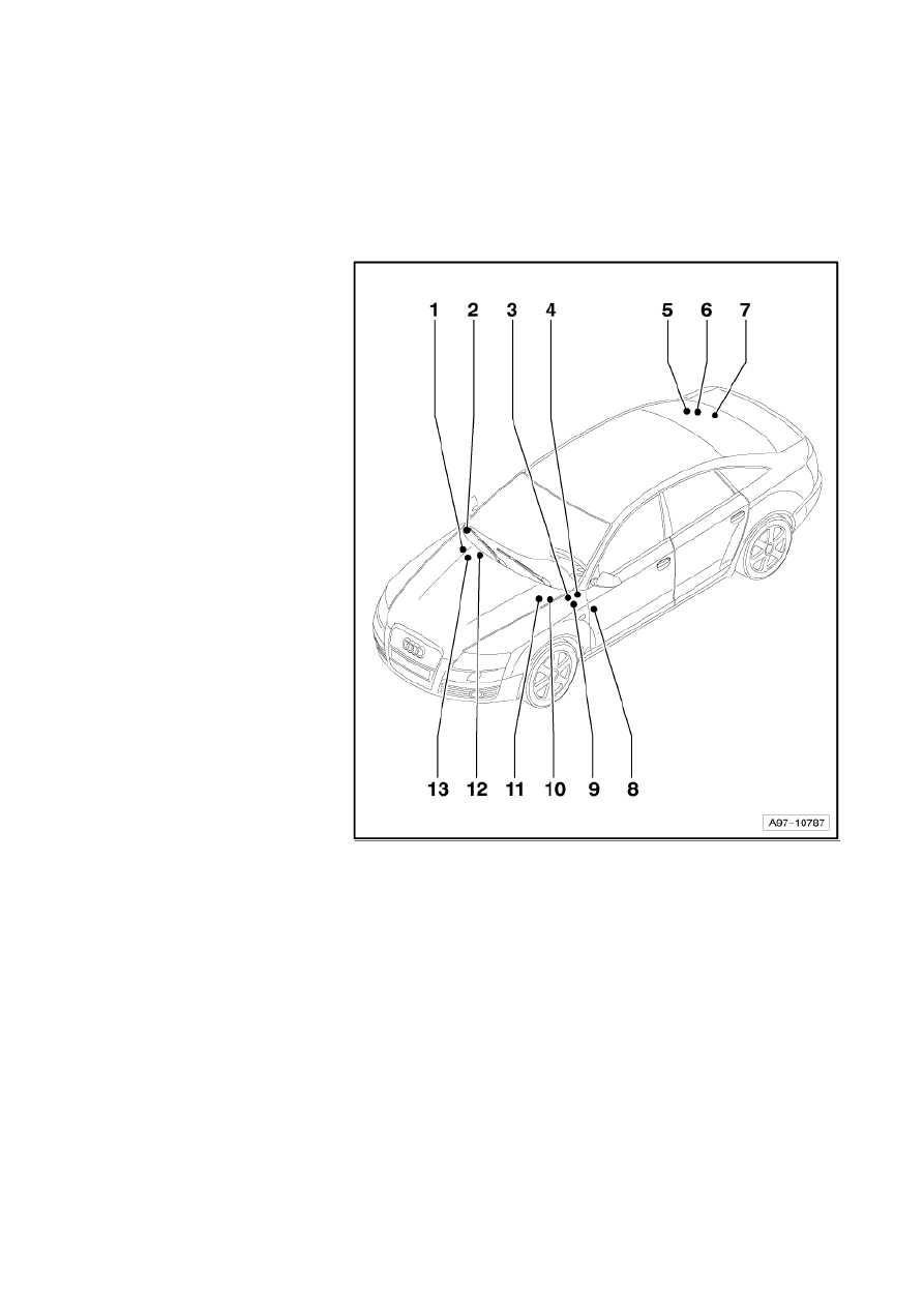
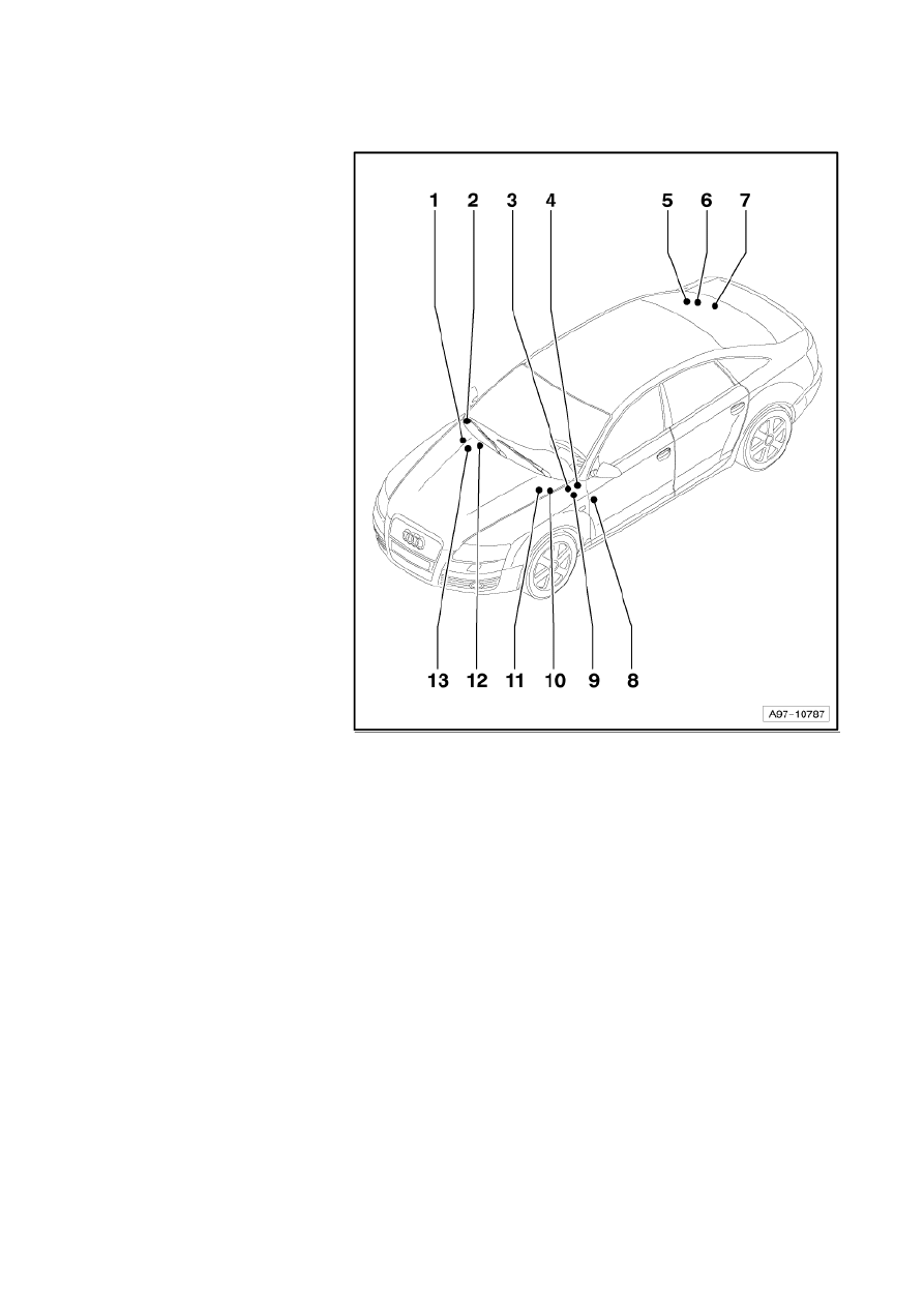
Overview of fuses
1 - Fuses in electronics box,
right in plenum chamber
Position of fuses, fuse
holder, from model year
2005
→
page 802/62
Position of fuses, fuse
holder left-hand drive, from
model year 2007
→
page
802/63
Position of fuses, fuse
holder right-hand drive,
from model year 2007
→
page 802/64
2 - Fuses on fuse holder, front
passenger side
Location of fuses (SC) on
fuse holder
→
page
802/35
Location of fuses (SB) on
fuse holder, right-hand
drive
→
page 802/28
Position of fuses (SC) on
fuse holder, from model
year 2005
→
page 802/36
Position of fuses (SC) on
fuse holder, left-hand
drive, from model year
2007
→
page 802/39
Position of fuses (SC) on
fuse holder, left-hand
drive, from model year
2009
→
page
→
802/42
Position of fuses (SB) on fuse holder, right-hand drive, from model year 2007
→
page 802/29
Position of fuses (SB) on fuse holder, right-hand drive, from model year 2009
→
page 802/32
Strona 1 z 77
WI-XML
2011-05-20
file://C:\ElsaWin\docs\slp\A\en-GB\A005A6200802.htm

Audi A6
Fitting Locations
No. 802 / 2
3 - Fuses on steering cross
member
Position of fuses, fuse
holder
→
page 802/70
4 - Fuses on onboard supply
control unit -J519-
Position of fuses, fuse
holder
→
page 802/61
5 - Fuses (SF) on fuse holder
F
Location fuse holder
→
page 802/52
Position of fuses, fuse
holder, from model year
2005
→
page 802/53
Position of fuses, fuse
holder, from model year
2007
→
page 802/55
Position of fuses, fuse
holder, from model year
2009
→
page 802/57
6 - Fuses, on right in luggage
compartment
Position of fuses, fuse
holder, from model year
2005
→
page 802/67
Position of fuses, fuse
holder, from model year
2007
→
page 802/69
7 - Fuses in luggage
compartment, rear right,
on the battery
Position of fuses, fuse holder, from model year 2007
→
page 802/72
Strona 2 z 77
WI-XML
2011-05-20
file://C:\ElsaWin\docs\slp\A\en-GB\A005A6200802.htm

Audi A6
Fitting Locations
No. 802 / 3
8 - Fuses on fuse holder,
driver side
Location of fuses (SB) on
fuse holder
→
page
802/18
Location of fuses (SC) on
fuse holder, right-hand
drive
→
page 802/45
Position of fuses (SB) on
fuse holder, from model
year 2005
→
page 802/19
Position of fuses (SB) on
fuse holder, left-hand
drive, from model year
2007
→
page 802/22
Position of fuses (SB) on
fuse holder, left-hand
drive, from model year
2009
→
page 802/25
Position of fuses (SC) on
fuse holder, right-hand
drive, from model year
2007
→
page 802/46
Position of fuses (SC) on
fuse holder, right-hand
drive, from model year
2009
→
page 802/49
9 - Fuses behind driver's
storage compartment
Position of fuses, fuse
holder, from model year
2005
→
page 802/59
Position of fuses, fuse holder left-hand drive, from model year 2007
→
page 802/60
Position of fuses, fuse holder right-hand drive, from model year 2007
→
page 802/60
Strona 3 z 77
WI-XML
2011-05-20
file://C:\ElsaWin\docs\slp\A\en-GB\A005A6200802.htm
Audi A6
Fitting Locations
No. 802 / 4
10 - Fuses (SA) on fuse holder
A
Location fuse holder
→
page 802/6
Location fuse holder, right-
hand drive
→
page 802/13
Position of fuses, fuse
holder, from model year
2005
→
page 802/7
Position of fuses, fuse
holder left-hand drive, from
model year 2007
→
page
802/9
Position of fuses, fuse
holder left-hand drive, from
model year 2009
→
page
802/11
Position of fuses, fuse
holder right-hand drive,
from model year 2007
→
page 802/14
Position of fuses, fuse
holder right-hand drive,
from model year 2009
→
page 802/16
11 - Fuses in electronics box,
left in plenum chamber
Position of fuses, fuse
holder left-hand drive, from
model year 2007
→
page
802/65
Position of fuses, fuse
holder right-hand drive,
from model year 2007
→
page 802/66
12 - Fuses on coupling station, lower part of right A-pillar
Position of fuses, fuse holder
→
page 802/73
Strona 4 z 77
WI-XML
2011-05-20
file://C:\ElsaWin\docs\slp\A\en-GB\A005A6200802.htm

Audi A6
Fitting Locations
No. 802 / 5
13 - Fuses on main fuse carrier
electronics box, right in
plenum chamber
Position of fuses, fuse
holder
→
page 802/71
Strona 5 z 77
WI-XML
2011-05-20
file://C:\ElsaWin\docs\slp\A\en-GB\A005A6200802.htm
Audi A6
Fitting Locations
No. 802 / 6
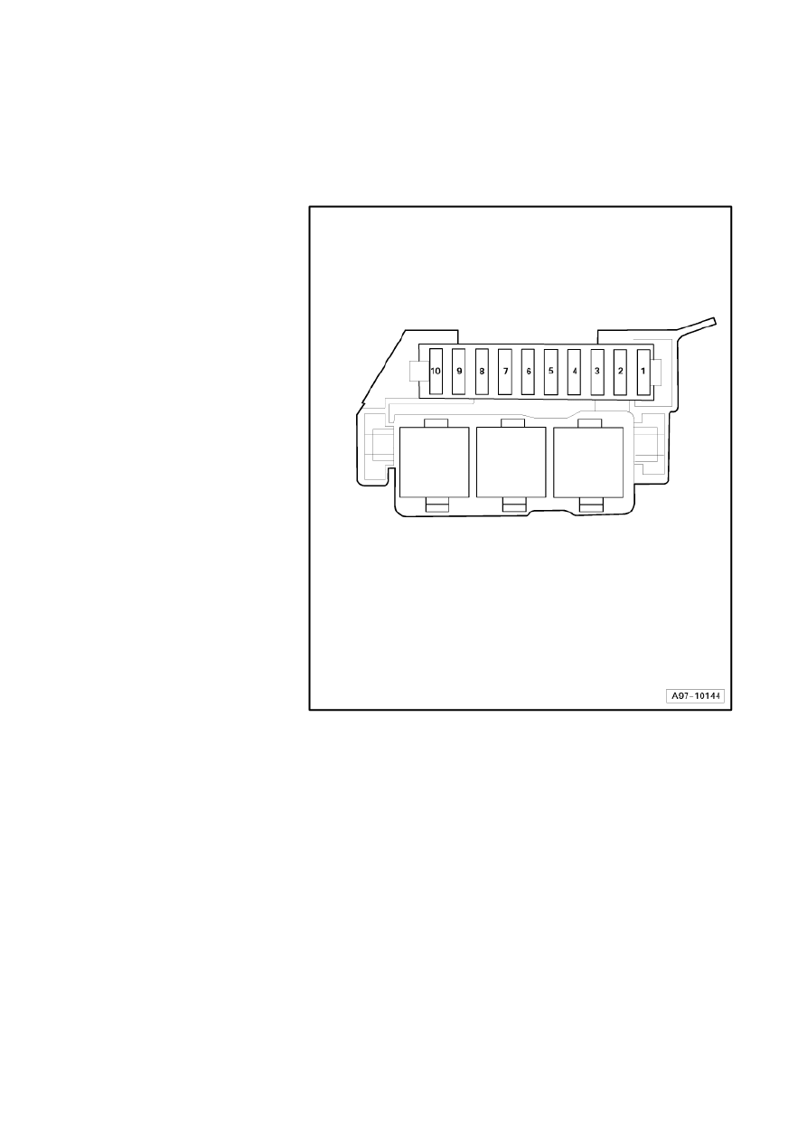
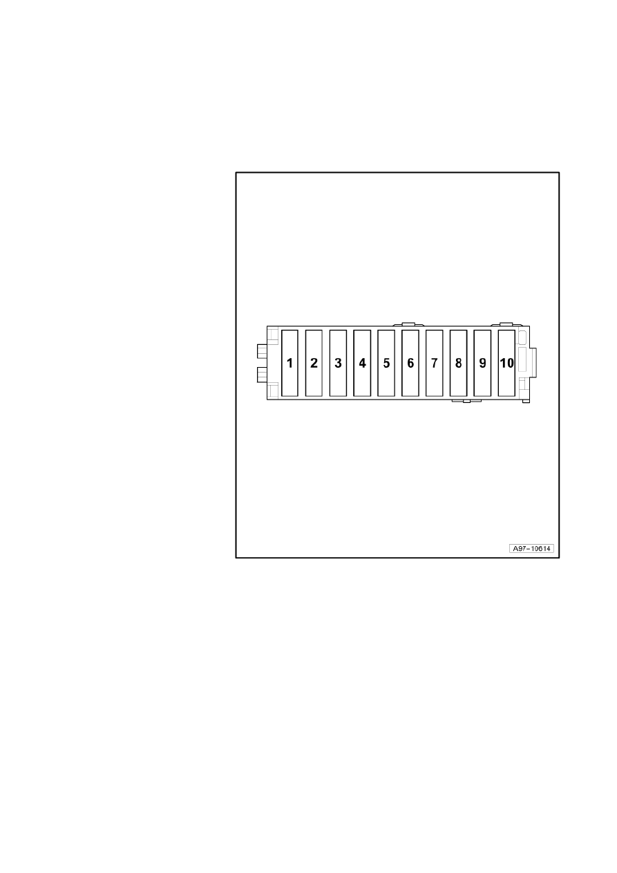
Location of fuses (SA), in electronics box left in plenum chamber
Fuse colours
40 A - orange
30 A - green
25 A - white
20 A - yellow
15 A - blue
10 A - red
7.5 A - brown
5 A - beige
3 A - purple
Strona 6 z 77
WI-XML
2011-05-20
file://C:\ElsaWin\docs\slp\A\en-GB\A005A6200802.htm

Audi A6
Fitting Locations
No. 802 / 7
Position of fuses, fuse holder, from model year 2005
No. Current Flow Diagram
designation
Nominal
value
Function/component
Terminal
1
- SA11 - Fuse 1 on fuse
holder in engine
compartment
15A
- J569
-
Brake servo relay
30
2
-
SA12 - Fuse 2 on fuse
holder in engine
compartment
20A
30A
15A
-
N... -
N... -
N184
-
J179
-
J360
-
J724
-
N144
-
N145
-
V157
-
V275
-
Ignition coils (BBJ, BDW, AUK)
Ignition coils (BAT, BGS)
Clutch actuator breather valve
Automatic glow period control unit
High heat output relay
Turbocharger 1 control unit
Left electrohydraulic engine mounting
solenoid valve
Right electrohydraulic engine mounting
solenoid valve
Intake manifold flap motor
Intake manifold flap 2 motor
87
3
-
SA13 - Fuse 3 on fuse
holder in engine
compartment
10A
15A
-
J151
-
J496
-
N276
-
N290
-
N205
-
N208
-
N318
-
N319
-
F265
-
V157
-
V183
-
Continued coolant circulation relay (BBJ,
BDW, BAT)
Additional coolant pump relay (AUK,
BGS)
Fuel pressure regulating valve (BMK)
Fuel metering valve (BMK)
Inlet camshaft control valve 1 (AUK,
BBJ, BDW, BAT, BGS)
Inlet camshaft control valve 2 (AUK,
BBJ, BDW, BAT)
Exhaust camshaft control valve 1 (AUK,
BBJ, BAT, BGS)
Exhaust camshaft control valve 2 (AUK,
BBJ, BDW, BAT)
Map-controlled engine cooling system
thermostat (BGS)
Intake manifold flap motor (BGS)
Variable intake manifold motor (BGS)
87
Strona 7 z 77
WI-XML
2011-05-20
file://C:\ElsaWin\docs\slp\A\en-GB\A005A6200802.htm

Audi A6
Fitting Locations
No. 802 / 8
No. Current Flow Diagram
designation
Nominal
value
Function/component
Terminal
4
-
SA14 - Fuse 4 on fuse
holder in engine
compartment
15A
-
J623
-
J624
-
J248
-
J361
-
Engine control unit
Engine control unit 2 (BGS)
Diesel direct injection system control unit
Simos control unit (injectors AUK)
87
5
-
SA15 - Fuse 5 on fuse
holder in engine
compartment
15A
10A¹)
-
G70
-
J299
-
N80
-
N112
-
N144
-
N145
-
N156
-
N335
-
Air mass meter
Secondary air pump relay
Activated charcoal filter system solenoid
valve 1
Secondary air inlet valve
Left electrohydraulic engine mounting
solenoid valve
Right electrohydraulic engine mounting
solenoid valve
Variable intake manifold change-over
valve
Variable intake manifold change-over
valve
EKP
6
- SA16 - Fuse 6 on fuse
holder in engine
compartment
15A
- Z19 -
Z28 -
Lambda probe heater
Lambda probe 2 heater
87
7
- SA17 - Fuse 7 on fuse
holder in engine
compartment
15A
- Z29 -
Z30 -
Lambda probe 1 heater after catalytic
converter
Lambda probe 2 heater after catalytic
converter
EKP
8
- SA18 - Fuse 8 on fuse
holder in engine
compartment
5A
- J623
-
Engine control unit
30
9
- SA19 - Fuse 9 on fuse
holder in engine
compartment
5A
- V7 -
Radiator fan
87
10 - SA20 - Fuse 10 on fuse
holder in engine
compartment
10A
- J217
-
Automatic gearbox control unit
87
¹) Engine BGS
Strona 8 z 77
WI-XML
2011-05-20
file://C:\ElsaWin\docs\slp\A\en-GB\A005A6200802.htm

Audi A6
Fitting Locations
No. 802 / 9
Position of fuses, fuse holder, left-hand drive, from model year 2007
No. Current Flow Diagram designation
Nominal
value
Function/component
Terminal
1
- SA1 - Fuse 1 on fuse holder A
15A
- J569 - Brake servo
relay
30
2
- SA2 - Fuse 2 on fuse holder A
20A
30A
15A
- J179 - Automatic glow
period control unit
J360 - High heat
output relay
J724 - Turbocharger 1
control unit
N... - Ignition coils
(BBJ, BDW, AUK)
N... - Ignition coils
(BAT, BXA, BDX)
N144 - Left
electrohydraulic engine
mounting solenoid
valve
N145 - Right
electrohydraulic engine
mounting solenoid
valve
N184 - Clutch actuator
breather valve
V157 - Intake manifold
flap motor
V275 - Intake manifold
flap 2 motor
87
3
- SA3 - Fuse 3 on fuse holder A
10A
- J151 - Continued
coolant circulation
relay (BBJ, BDW,
BAT)
J496 - Additional
coolant pump relay
(AUK, BXA)
N205 - Inlet camshaft
control valve 1 (AUK,
BBJ, BDW, BAT, BXA)
N208 - Inlet camshaft
control valve 2 (AUK,
BBJ, BDW, BAT)
N276 - Fuel pressure
regulating valve (BMK)
N290 - Fuel metering
valve (BMK)
N318 - Exhaust
camshaft control valve
1 (AUK, BBJ, BAT,
BXA)
N319 - Exhaust
camshaft control valve
2 (AUK, BBJ, BDW,
BAT)
F... - Actuator for
camshaft adjustment
(BDX)
87
Strona 9 z 77
WI-XML
2011-05-20
file://C:\ElsaWin\docs\slp\A\en-GB\A005A6200802.htm

F265 - Map-controlled
engine cooling system
thermostat (BXA)
V157 - Intake manifold
flap motor (BXA)
V183 - Variable intake
manifold motor (BXA)
Strona 10 z 77
WI-XML
2011-05-20
file://C:\ElsaWin\docs\slp\A\en-GB\A005A6200802.htm

Audi A6
Fitting Locations
No. 802 / 10
No. Current Flow Diagram designation
Nominal
value
Function/component
Terminal
4
- SA4-Fuse 4 on fuse holder A
15A
- J623 - Engine control
unit
J624 - Engine control
unit 2
87
5
- SA5 - Fuse 5 on fuse holder A
15A
- G70 - Air mass meter
J299 - Secondary air
pump relay
N80 - Activated
charcoal filter system
solenoid valve 1
N112 - Secondary air
inlet valve
N144 - Left
electrohydraulic engine
mounting solenoid
valve
N145 - Right
electrohydraulic engine
mounting solenoid
valve
N156 - Variable intake
manifold change-over
valve
N335 - Variable intake
manifold change-over
valve
EKP
6
- SA6-Fuse 6 on fuse holder A
15A
- Z19 - Lambda probe
heater
Z28 - Lambda probe 2
heater
87
7
- SA7-Fuse 7 on fuse holder A
15A
- Z29 - Lambda probe 1
heater after catalytic
converter
Z30 - Lambda probe 2
heater after catalytic
converter
EKP
8
- SA8 - Fuse 8 on fuse holder A
5A
- J623 - Engine control
unit
30
9
- SA9 - Fuse 9 on fuse holder A
5A
- V7 - Radiator fan
87
10 - SA10 - Fuse 10 on fuse holder A
10A
- J217 - Automatic
gearbox control unit
87
Strona 11 z 77
WI-XML
2011-05-20
file://C:\ElsaWin\docs\slp\A\en-GB\A005A6200802.htm

Audi A6
Fitting Locations
No. 802 / 11
Position of fuses, fuse holder, left-hand drive, from model year 2009
No. Current Flow Diagram designation
Nominal
value
Function/component
Terminal
1
- SA1 - Fuse 1 on fuse holder A
15A
- J569 - Brake servo relay
30
2
- SA2 - Fuse 2 on fuse holder A
20A
30A
15A
- J179 - Automatic glow period
control unit ¹)
J360 - High heat output
relay¹)
J338 - Throttle valve
module¹)
J724 - Turbocharger 1
control unit
N...-Ignition coils
N75 - Charge pressure
control solenoid valve¹)
N79 - Heater element for
crankcase breather¹)
N144 - Left electrohydraulic
engine mounting solenoid
valve¹)
N145 - Right electrohydraulic
engine mounting solenoid
valve¹)
N275 - Air filter bypass flap
valve¹)
N345 - Exhaust gas
recirculation cooler change-
over valve¹)
N428 - Valve for oil pressure
control¹)
87
3
- SA3 - Fuse 3 on fuse holder A
10A
- J151 - Continued coolant
circulation relay
J496-Additional coolant
pump relay
N144 - Left electrohydraulic
engine mounting solenoid
valve
N145 - Right electrohydraulic
engine mounting solenoid
valve
N205 - Inlet camshaft control
valve 1
N208 - Inlet camshaft control
valve 2
N276 - Fuel pressure
regulating valve¹)
N290 - Fuel metering valve¹)
N318 - Exhaust camshaft
control valve 1
N319 - Exhaust camshaft
control valve 2
F... - Actuator for camshaft
adjustment
F265 - Map-controlled
engine cooling system
thermostat
V157 - Intake manifold flap
87
Strona 12 z 77
WI-XML
2011-05-20
file://C:\ElsaWin\docs\slp\A\en-GB\A005A6200802.htm

motor
V183 - Variable intake
manifold motor
¹) models with diesel engine
Strona 13 z 77
WI-XML
2011-05-20
file://C:\ElsaWin\docs\slp\A\en-GB\A005A6200802.htm
Audi A6
Fitting Locations
No. 802 / 12
No. Current Flow Diagram designation
Nominal
value
Function/component
Terminal
4
- SA4-Fuse 4 on fuse holder A
15 A
- J623 - Engine control unit
J624 - Engine control unit 2
87
5
- SA5 - Fuse 5 on fuse holder A
15 A
- J299 - Secondary air pump
relay
N80 - Activated charcoal
filter system solenoid valve
1
N112 - Secondary air inlet
valve
N144 - Left electrohydraulic
engine mounting solenoid
valve
N145 - Right
electrohydraulic engine
mounting solenoid valve
N156 - Variable intake
manifold change-over valve
N249 - Turbocharger air
recirculation valve
N276 - Fuel pressure
regulating valve
N290 - Fuel metering valve
N316 - Intake manifold flap
valve
N320 - Secondary air inlet
valve 2
N335 - Variable intake
manifold change-over valve
N402 - Fuel metering valve
2
N428 - Valve for oil
pressure control
V144 - Fuel system
diagnostic pump
EKP
6
- SA6-Fuse 6 on fuse holder A
15 A
- Z19 - Lambda probe heater
Z28 - Lambda probe 2
heater
87
7
- SA7-Fuse 7 on fuse holder A
15 A
- Z29 - Lambda probe 1
heater after catalytic
converter
Z30 - Lambda probe 2
heater after catalytic
converter
EKP
8
- SA8 - Fuse 8 on fuse holder A
5 A
20 A¹)
- J623 - Engine control unit
J832 - Relay for
supplementary fuel pump¹)
30
9
- SA9 - Fuse 9 on fuse holder A
5 A
- V7 - Radiator fan
87
10 - SA10 - Fuse 10 on fuse holder A
10 A
- J217 - Automatic gearbox
control unit
87
¹) models with diesel engine
Strona 14 z 77
WI-XML
2011-05-20
file://C:\ElsaWin\docs\slp\A\en-GB\A005A6200802.htm
Audi A6
Fitting Locations
No. 802 / 13
Location of fuses (SA), in electronics box left in plenum chamber, right-hand
drive
Fuse colours
40 A - orange
30 A - green
25 A - white
20 A - yellow
15 A - blue
10 A - red
7.5 A - brown
5 A - beige
3 A - purple
Strona 15 z 77
WI-XML
2011-05-20
file://C:\ElsaWin\docs\slp\A\en-GB\A005A6200802.htm

Audi A6
Fitting Locations
No. 802 / 14
Position of fuses, fuse holder, right-hand drive, from model year 2007
No. Current Flow Diagram designation
Nominal
value
Function/component
Terminal
1
- SA1 - Fuse 1 on fuse holder A
15A
- J569 - Brake servo
relay
30
2
- SA2 - Fuse 2 on fuse holder A
20A
30A
15A
- J179 - Automatic glow
period control unit
J360 - High heat
output relay
J724 - Turbocharger 1
control unit
N... - Ignition coils
(BBJ, BDW, AUK)
N... - Ignition coils
(BAT, BXA, BDX)
N144 - Left
electrohydraulic engine
mounting solenoid
valve
N145 - Right
electrohydraulic engine
mounting solenoid
valve
N184 - Clutch actuator
breather valve
V157 - Intake manifold
flap motor
V275 - Intake manifold
flap 2 motor
87
3
- SA3 - Fuse 3 on fuse holder A
10A
- J151 - Continued
coolant circulation
relay (BBJ, BDW,
BAT)
J496 - Additional
coolant pump relay
(AUK, BXA)
N205 - Inlet camshaft
control valve 1 (AUK,
BBJ, BDW, BAT, BXA)
N208 - Inlet camshaft
control valve 2 (AUK,
BBJ, BDW, BAT)
N276 - Fuel pressure
regulating valve (BMK)
N290 - Fuel metering
valve (BMK)
N318 - Exhaust
camshaft control valve
1 (AUK, BBJ, BAT,
BXA)
N319 - Exhaust
camshaft control valve
2 (AUK, BBJ, BDW,
BAT)
F... - Actuator for
camshaft adjustment
(BDX)
87
Strona 16 z 77
WI-XML
2011-05-20
file://C:\ElsaWin\docs\slp\A\en-GB\A005A6200802.htm

F265 - Map-controlled
engine cooling system
thermostat (BXA)
V157 - Intake manifold
flap motor (BXA)
V183 - Variable intake
manifold motor (BXA)
Strona 17 z 77
WI-XML
2011-05-20
file://C:\ElsaWin\docs\slp\A\en-GB\A005A6200802.htm

Audi A6
Fitting Locations
No. 802 / 15
No. Current Flow Diagram designation
Nominal
value
Function/component
Terminal
4
- SA4-Fuse 4 on fuse holder A
15A
- J623 - Engine control
unit
J624 - Engine control
unit 2
87
5
- SA5 - Fuse 5 on fuse holder A
15A
- G70 - Air mass meter
J299 - Secondary air
pump relay
N80 - Activated
charcoal filter system
solenoid valve 1
N112 - Secondary air
inlet valve
N144 - Left
electrohydraulic engine
mounting solenoid
valve
N145 - Right
electrohydraulic engine
mounting solenoid
valve
N156 - Variable intake
manifold change-over
valve
N335 - Variable intake
manifold change-over
valve
EKP
6
- SA6-Fuse 6 on fuse holder A
15A
- Z19 - Lambda probe
heater
Z28 - Lambda probe 2
heater
87
7
- SA7-Fuse 7 on fuse holder A
15A
- Z29 - Lambda probe 1
heater after catalytic
converter
Z30 - Lambda probe 2
heater after catalytic
converter
EKP
8
- SA8 - Fuse 8 on fuse holder A
5A
- J623 - Engine control
unit
30
9
- SA9 - Fuse 9 on fuse holder A
5A
- V7 - Radiator fan
87
10 - SA10 - Fuse 10 on fuse holder A
10A
- J217 - Automatic
gearbox control unit
87
Strona 18 z 77
WI-XML
2011-05-20
file://C:\ElsaWin\docs\slp\A\en-GB\A005A6200802.htm

Audi A6
Fitting Locations
No. 802 / 16
Position of fuses, fuse holder, right-hand drive, from model year 2009
No. Current Flow Diagram designation
Nominal
value
Function/component
Terminal
1
- SA1 - Fuse 1 on fuse holder A
15A
- J569 - Brake servo relay
30
2
- SA2 - Fuse 2 on fuse holder A
20A
30A
15A
- J179 - Automatic glow period
control unit ¹)
J360 - High heat output
relay¹)
J338 - Throttle valve
module¹)
J724 - Turbocharger 1
control unit
N...-Ignition coils
N75 - Charge pressure
control solenoid valve¹)
N79 - Heater element for
crankcase breather¹)
N144 - Left electrohydraulic
engine mounting solenoid
valve¹)
N145 - Right electrohydraulic
engine mounting solenoid
valve¹)
N275 - Air filter bypass flap
valve¹)
N345 - Exhaust gas
recirculation cooler change-
over valve¹)
N428 - Valve for oil pressure
control¹)
87
3
- SA3 - Fuse 3 on fuse holder A
10A
- J151 - Continued coolant
circulation relay
J496-Additional coolant
pump relay
N144 - Left electrohydraulic
engine mounting solenoid
valve
N145 - Right electrohydraulic
engine mounting solenoid
valve
N205 - Inlet camshaft control
valve 1
N208 - Inlet camshaft control
valve 2
N276 - Fuel pressure
regulating valve¹)
N290 - Fuel metering valve¹)
N318 - Exhaust camshaft
control valve 1
N319 - Exhaust camshaft
control valve 2
F... - Actuator for camshaft
adjustment
F265 - Map-controlled
engine cooling system
thermostat
V157 - Intake manifold flap
87
Strona 19 z 77
WI-XML
2011-05-20
file://C:\ElsaWin\docs\slp\A\en-GB\A005A6200802.htm

motor
V183 - Variable intake
manifold motor
¹) models with diesel engine
Strona 20 z 77
WI-XML
2011-05-20
file://C:\ElsaWin\docs\slp\A\en-GB\A005A6200802.htm

Audi A6
Fitting Locations
No. 802 / 17
No. Current Flow Diagram designation
Nominal
value
Function/component
Terminal
4
- SA4-Fuse 4 on fuse holder A
15 A
- J623 - Engine control unit
J624 - Engine control unit 2
87
5
- SA5 - Fuse 5 on fuse holder A
15 A
- J299 - Secondary air pump
relay
N80 - Activated charcoal
filter system solenoid valve
1
N112 - Secondary air inlet
valve
N144 - Left electrohydraulic
engine mounting solenoid
valve
N145 - Right
electrohydraulic engine
mounting solenoid valve
N156 - Variable intake
manifold change-over valve
N249 - Turbocharger air
recirculation valve
N276 - Fuel pressure
regulating valve
N290 - Fuel metering valve
N316 - Intake manifold flap
valve
N320 - Secondary air inlet
valve 2
N335 - Variable intake
manifold change-over valve
N402 - Fuel metering valve
2
N428 - Valve for oil
pressure control
V144 - Fuel system
diagnostic pump
EKP
6
- SA6-Fuse 6 on fuse holder A
15 A
- Z19 - Lambda probe heater
Z28 - Lambda probe 2
heater
87
7
- SA7-Fuse 7 on fuse holder A
15 A
- Z29 - Lambda probe 1
heater after catalytic
converter
Z30 - Lambda probe 2
heater after catalytic
converter
EKP
8
- SA8 - Fuse 8 on fuse holder A
5 A
20 A¹)
- J623 - Engine control unit
J832 - Relay for
supplementary fuel pump¹)
30
9
- SA9 - Fuse 9 on fuse holder A
5 A
- V7 - Radiator fan
87
10 - SA10 - Fuse 10 on fuse holder A
10 A
- J217 - Automatic gearbox
control unit
87
¹) models with diesel engine
Strona 21 z 77
WI-XML
2011-05-20
file://C:\ElsaWin\docs\slp\A\en-GB\A005A6200802.htm
Audi A6
Fitting Locations
No. 802 / 18
Location of fuses (SB), left dash panel
Fuse colours
40 A - orange
30 A - green
25 A - white
20 A - yellow
15 A - blue
10 A - red
7.5 A - brown
5 A - beige
3 A - purple
Strona 22 z 77
WI-XML
2011-05-20
file://C:\ElsaWin\docs\slp\A\en-GB\A005A6200802.htm

Audi A6
Fitting Locations
No. 802 / 19
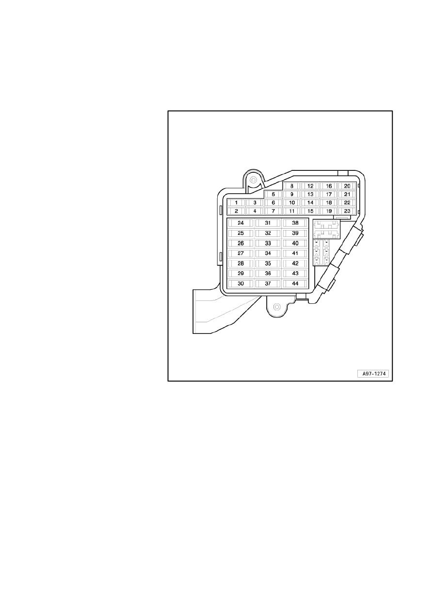
Position of fuses, fuse holder, from model year 2005
No. Current Flow Diagram designation
Nominal
value
Function/component
Terminal
1
- Vacant
2
- Vacant
3
-
SB3 - Fuse 3 on fuse holder
5A
- J361 - Simos control unit
J248 - Diesel direct
injection system control
unit
J623 - Engine control
unit
15
4
- SB4 - Fuse 4 on fuse holder
5A
- G266-Oil level and oil
temperature sender
15
5
- SB5 - Fuse 5 on fuse holder
5A
- G238 - Air quality sensor
G395 - Refrigerant
pressure and
temperature sender
15
6
- SB6 - Fuse 6 on fuse holder
5A
- J104 - ABS control unit
G476 - Clutch position
sender
15
7
- SB7 - Fuse 7 on fuse holder
5A
- T16 - Diagnostic
connector
15
8
- SB8 - Fuse 8 on fuse holder
5A
- J530 - Garage door
operation control unit
15
9
- SB9 - Fuse 9 on fuse holder
5A
- Y7 - Automatic anti-
dazzle interior mirror
15
10 - SB10 - Fuse 10 on fuse holder
5A
- J428 - Adaptive cruise
control unit
15
11 - SB11 - Fuse 11 on fuse holder
5A
- R64 - Remote control
receiver for auxiliary
heating
30
12 - SB12 - Fuse 12 on fuse holder
10A
- T16 - Diagnostic
connector
30
13 - SB13 - Fuse 13 on fuse holder
10A
- J527 - Steering column
electronics control unit
30
14 - SB14 - Fuse 14 on fuse holder
5A
- F - Brake light switch
30
Strona 23 z 77
WI-XML
2011-05-20
file://C:\ElsaWin\docs\slp\A\en-GB\A005A6200802.htm

Audi A6
Fitting Locations
No. 802 / 20
No. Current Flow Diagram designation
Nominal
value
Function/component
Terminal
15 - SB15 - Fuse 15 on fuse holder
10 A
- J285 - Control unit in
dash panel insert
30
16 - SB16 - Fuse 16 on fuse holder
10 A
- R36 - Telephone
transmitter and receiver
unit
30
17 - SB17 - Fuse 17 on fuse holder
10 A
- J104 - ABS control unit
30
18 - SB18 - Fuse 18 on fuse holder
5 A
- left and right headlight
with cornering lights
15
19 - SB19 - Fuse 19 on fuse holder
5 A
- G397 - Rain and light
detector sensor
30
20 - SB20 - Fuse 20 on fuse holder
5 A
- Z20 - Left washer jet
heater element
Z21 - Right washer jet
heater element
75
21 - SB21 - Fuse 21 on fuse holder
5 A
- R24 - Aerial amplifier
30
22 - Vacant
23 - SB23 - Fuse 23 on fuse holder
5 A
- J540 - Electric park and
handbrake control unit
30
24 - Vacant
25 - Vacant
26 - Vacant
27 - Vacant
28 - Vacant
29 - Vacant
Strona 24 z 77
WI-XML
2011-05-20
file://C:\ElsaWin\docs\slp\A\en-GB\A005A6200802.htm

Audi A6
Fitting Locations
No. 802 / 21
No. Current Flow Diagram designation
Nominal
value
Function/component
Terminal
30 - Vacant
31 - SB31 - Fuse 31 on fuse holder
15 A
- F4 - Reversing light
switch
G70 - Air mass meter
(TDI)
J217 - Automatic
gearbox control unit
15
32 - SB32 - Fuse 32 on fuse holder
30 A
- J519 - Onboard power
supply control unit
30
33 - SB33 - Fuse 33 on fuse holder
25 A
- J519 - Onboard power
supply control unit
30
34 - SB34 - Fuse 34 on fuse holder
25 A
- J519 - Onboard power
supply control unit
30
35 - SB35 - Fuse 35 on fuse holder
20 A
- J364 - Auxiliary heater
control unit
30
36 - SB36 - Fuse 36 on fuse holder
30 A
- J39 - Headlight washer
system relay
30
37 - SB37 - Fuse 37 on fuse holder
25 A
- J104 - ABS control unit
30
38 - SB38 - Fuse 38 on fuse holder
30 A
- J400 - Wiper motor
control unit
30
39 - SB39 - Fuse 39 on fuse holder
15 A
- J386 - Driver door
control unit
J388 - Rear left door
control unit
30
40
-
SB40 - Fuse 40 on fuse holder
25 A
-
J4 - Dual tone horn relay
H2 - Treble tone horn
H7 - Bass tone horn
30
41 - SB41 - Fuse 41 on fuse holder
40 A
- J126 - Fresh air blower
control unit
30
42 - SB42 - Fuse 42 on fuse holder
30 A
- E415 - Entry and start
authorisation switch
J518 - Entry and start
authorisation control unit
30
43 - SB43 - Fuse 43 on fuse holder
15 A
- V12 - Rear window
wiper motor
75
44 - SB44 - Fuse 44 on fuse holder
15 A
35 A
- J723 - Aerial reader unit
for keyless entry system
(up to October 2005)
V26 - Rear left window
regulator motor (from
November 2005)
V147 - Driver side
window regulator motor
(from November 2005)
30
Strona 25 z 77
WI-XML
2011-05-20
file://C:\ElsaWin\docs\slp\A\en-GB\A005A6200802.htm

Audi A6
Fitting Locations
No. 802 / 22
Position of fuses, fuse holder, left-hand drive, from model year 2007
No. Current Flow Diagram designation
Nominal
value
Function/component
Terminal
1
- Vacant
2
- Vacant
3
- SB3 - Fuse 3 on fuse holder B
5 A
- J623 - Engine control unit
15
4
- SB4 - Fuse 4 on fuse holder B
5 A
- G226 - Oil level and oil temperature
sender
15
5
- SB5 - Fuse 5 on fuse holder B
5 A
- G238 - Air quality sensor
G395 - Refrigerant pressure and
temperature sender
15
6
- SB6 - Fuse 6 on fuse holder B
5 A
- J104 - ABS control unit
G476 - Clutch position sender
15
7
- SB7 - Fuse 7 on fuse holder B
5 A
- T16 - Diagnostic connector
15
8
- SB8 - Fuse 8 on fuse holder B
5 A
- J530 - Garage door operation control
unit
15
9
- SB9 - Fuse 9 on fuse holder B
5 A
- Y7 - Automatic anti-dazzle interior
mirror
15
10 - SB10 - Fuse 10 on fuse holder B
5 A
- J428 - Adaptive cruise control unit
15
11 - SB11 - Fuse 11 on fuse holder B
5 A
- R64 - Remote control receiver for
auxiliary heating
30
12 - SB12 - Fuse 12 on fuse holder B
10 A
- T16 - Diagnostic connector
30
13 - SB13 - Fuse 13 on fuse holder B
10 A
- J527 - Steering column electronics
control unit
30
14 - SB14 - Fuse 14 on fuse holder B
5 A
- F - Brake light switch
30
Strona 26 z 77
WI-XML
2011-05-20
file://C:\ElsaWin\docs\slp\A\en-GB\A005A6200802.htm

Audi A6
Fitting Locations
No. 802 / 23
No. Current Flow Diagram designation
Nominal
value
Function/component
Terminal
15 - SB15 - Fuse 15 on fuse holder B
10 A
- J285 - Control unit in dash panel
insert
J533 - Data bus diagnostic interface
30
16 - SB16 - Fuse 16 on fuse holder B
10 A
- R36 - Telephone transmitter and
receiver unit
30
17 - SB17 - Fuse 17 on fuse holder B
10 A
- J104 - ABS control unit
30
18 - SB18 - Fuse 18 on fuse holder B
5 A
- Left headlight with cornering lights
J745 - Cornering light and headlight
range control unit
15
19 - SB19 - Fuse 19 on fuse holder B
5 A
- G397 - Rain and light detector
sensor
30
20 - SB20 - Fuse 20 on fuse holder B
5 A
- Z20 - Left washer jet heater element
Z21 - Right washer jet heater
element
75
21 - SB21 - Fuse 21 on fuse holder B
10 A
- Seat adjustment lumbar support
driver seat
30
22 - Vacant
23 - SB23 - Fuse 23 on fuse holder B
5 A
- J540 - Electric park and handbrake
control unit
30
24 - Vacant
25 - Vacant
26 - Vacant
27 - Vacant
28 - Vacant
29 - Vacant
30 - Vacant
Strona 27 z 77
WI-XML
2011-05-20
file://C:\ElsaWin\docs\slp\A\en-GB\A005A6200802.htm

Audi A6
Fitting Locations
No. 802 / 24
No. Current Flow Diagram designation
Nominal
value
Function/component
Terminal
31 - SB31 - Fuse 31 on fuse holder B
15 A
- F4 - Reversing light
switch
G70 - Air mass meter
(TDI)
J217 - Automatic
gearbox control unit
15
32 - SB32 - Fuse 32 on fuse holder B
30 A
- J519 - Onboard power
supply control unit
30
33 - SB33 - Fuse 33 on fuse holder B
25 A
- J519 - Onboard power
supply control unit
30
34 - SB34 - Fuse 34 on fuse holder B
25 A
- J519 - Onboard power
supply control unit
30
35 - SB35 - Fuse 35 on fuse holder B
20 A
- J364 - Auxiliary heater
control unit
30
36 - SB36 - Fuse 36 on fuse holder B
30 A
- J39 - Headlight washer
system relay
30
37 - SB37 - Fuse 37 on fuse holder B
25 A
- J104 - ABS control unit
30
38 - SB38 - Fuse 38 on fuse holder B
30 A
- J400 - Wiper motor
control unit
30
39 - SB39 - Fuse 39 on fuse holder B
15 A
- J386 - Driver door
control unit
J388 - Rear left door
control unit
30
40 - SB40 - Fuse 40 on fuse holder B
25 A
- J4 - Dual tone horn
relay
H2 - Treble tone horn
H7 - Bass tone horn
30
41 - SB41 - Fuse 41 on fuse holder B
40 A
- J126 - Fresh air blower
control unit
30
42 - SB42 - Fuse 42 on fuse holder B
30 A
- E415 - Entry and start
authorisation switch
J518 - Entry and start
authorisation control
unit
30
43 - SB43 - Fuse 43 on fuse holder B
15 A
- V12 - Rear window
wiper motor
75
44 - SB44 - Fuse 44 on fuse holder B
35 A
- V26 - Rear left window
regulator motor
V147 - Driver side
window regulator
motor
30
Strona 28 z 77
WI-XML
2011-05-20
file://C:\ElsaWin\docs\slp\A\en-GB\A005A6200802.htm

Audi A6
Fitting Locations
No. 802 / 25
Position of fuses, fuse holder, left-hand drive, from model year 2009
No. Current Flow Diagram designation
Nominal
value
Function/component
Terminal
1
- Vacant
2
- Vacant
3
- SB3 - Fuse 3 on fuse holder B
5 A
- J623 - Engine control unit
15
4
- SB4 - Fuse 4 on fuse holder B
5 A
- G226 - Oil level and oil temperature
sender
15
5
- SB5 - Fuse 5 on fuse holder B
5 A
- G238 - Air quality sensor
G395 - Refrigerant pressure and
temperature sender
15
6
- SB6 - Fuse 6 on fuse holder B
5 A
- J104 - ABS control unit
G476 - Clutch position sender
15
7
- SB7 - Fuse 7 on fuse holder B
5 A
- T16 - Diagnostic connector
15
8
- SB8 - Fuse 8 on fuse holder B
5 A
- J530 - Garage door operation control
unit
15
9
- SB9 - Fuse 9 on fuse holder B
5 A
- Y7 - Automatic anti-dazzle interior
mirror
15
10 - SB10 - Fuse 10 on fuse holder B
5 A
- J428 - Adaptive cruise control unit
15
11 - SB11 - Fuse 11 on fuse holder B
5 A
- R64 - Remote control receiver for
auxiliary heating
30
12 - SB12 - Fuse 12 on fuse holder B
10 A
- T16 - Diagnostic connector
30
13 - SB13 - Fuse 13 on fuse holder B
10 A
- J527 - Steering column electronics
control unit
30
14 - Vacant
Strona 29 z 77
WI-XML
2011-05-20
file://C:\ElsaWin\docs\slp\A\en-GB\A005A6200802.htm

Audi A6
Fitting Locations
No. 802 / 26
No. Current Flow Diagram designation
Nominal
value
Function/component
Terminal
15 - SB15 - Fuse 15 on fuse holder B
10 A
- J285 - Control unit in dash panel
insert
J533 - Data bus diagnostic interface
30
16 - SB16 - Fuse 16 on fuse holder B
5 A
- J794 - Control unit for information
electronics 1
R126 - Telephone bracket
30
17 - SB17 - Fuse 17 on fuse holder B
10 A
- J104 - ABS control unit
30
18 - SB18 - Fuse 18 on fuse holder B
5 A
- Left headlight with cornering lights
J745 - Cornering light and headlight
range control unit
15
19 - SB19 - Fuse 19 on fuse holder B
5 A
- G397 - Rain and light detector
sensor
30
20 - SB20 - Fuse 20 on fuse holder B
5 A
- Z20 - Left washer jet heater element
Z21 - Right washer jet heater
element
75
21 - SB21 - Fuse 21 on fuse holder B
10 A
- Seat adjustment lumbar support
driver seat
30
22 - SB22 - Fuse 22 on fuse holder B
5 A
- J685 - Display unit for front
information display and operating
unit control unit
30
23 - SB23 - Fuse 23 on fuse holder B
5 A
- J540 - Electric park and handbrake
control unit
30
24 - Vacant
25 - Vacant
26 - Vacant
27 - Vacant
28 - Vacant
29 - Vacant
30 - Vacant
Strona 30 z 77
WI-XML
2011-05-20
file://C:\ElsaWin\docs\slp\A\en-GB\A005A6200802.htm

Audi A6
Fitting Locations
No. 802 / 27
No. Current Flow Diagram designation
Nominal
value
Function/component
Terminal
31 - SB31 - Fuse 31 on fuse holder B
15 A
- F4 - Reversing light
switch
G70 - Air mass meter
(TDI)
J217 - Automatic
gearbox control unit
15
32 - SB32 - Fuse 32 on fuse holder B
30 A
- J519 - Onboard power
supply control unit
30
33 - SB33 - Fuse 33 on fuse holder B
25 A
- J519 - Onboard power
supply control unit
30
34 - SB34 - Fuse 34 on fuse holder B
25 A
- J519 - Onboard power
supply control unit
30
35 - SB35 - Fuse 35 on fuse holder B
20 A
- J364 - Auxiliary heater
control unit
30
36 - SB36 - Fuse 36 on fuse holder B
30 A
- J39 - Headlight washer
system relay
30
37 - SB37 - Fuse 37 on fuse holder B
25 A
- J104 - ABS control unit
30
38 - SB38 - Fuse 38 on fuse holder B
30 A
- J400 - Wiper motor
control unit
30
39 - SB39 - Fuse 39 on fuse holder B
15 A
- J386 - Driver door
control unit
J388 - Rear left door
control unit
30
40 - SB40 - Fuse 40 on fuse holder B
25 A
- J4 - Dual tone horn
relay
H2 - Treble tone horn
H7 - Bass tone horn
30
41 - SB41 - Fuse 41 on fuse holder B
40 A
- J126 - Fresh air blower
control unit
30
42 - SB42 - Fuse 42 on fuse holder B
30 A
- E415 - Entry and start
authorisation switch
J518 - Entry and start
authorisation control
unit
30
43 - SB43 - Fuse 43 on fuse holder B
15 A
- V12 - Rear window
wiper motor
75
44 - SB44 - Fuse 44 on fuse holder B
35 A
- V26 - Rear left window
regulator motor
V147 - Driver side
window regulator
motor
30
Strona 31 z 77
WI-XML
2011-05-20
file://C:\ElsaWin\docs\slp\A\en-GB\A005A6200802.htm
Audi A6
Fitting Locations
No. 802 / 28
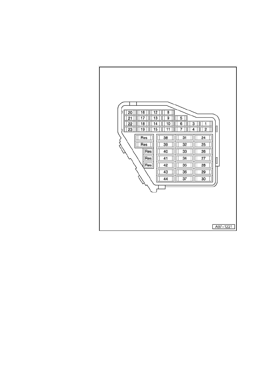
Location of fuses (SB), right dash panel, right-hand drive
Fuse colours
40 A - orange
30 A - green
25 A - white
20 A - yellow
15 A - blue
10 A - red
7.5 A - brown
5 A - beige
3 A - purple
Strona 32 z 77
WI-XML
2011-05-20
file://C:\ElsaWin\docs\slp\A\en-GB\A005A6200802.htm

Audi A6
Fitting Locations
No. 802 / 29
Position of fuses, fuse holder, right-hand drive, from model year 2007
No. Current Flow Diagram designation
Nominal
value
Function/component
Terminal
1
- Vacant
2
- Vacant
3
- SB3 - Fuse 3 on fuse holder B
5 A
- J446 - Parking aid control unit
30
4
- SB4 - Fuse 4 on fuse holder B
5 A
- J446 - Parking aid control unit
15
5
- SB5 - Fuse 5 on fuse holder B
5 A
- G238 - Air quality sensor
G395 - Refrigerant pressure and
temperature sender
15
6
- SB6 - Fuse 6 on fuse holder B
5 A
- J587 - Selector lever sensors control
unit
15
7
- SB7 - Fuse 7 on fuse holder B
5 A
- T16 - Diagnostic connector
15
8
- SB8 - Fuse 8 on fuse holder B
5 A
- Preparation for mobile telephone
15
9
- SB9 - Fuse 9 on fuse holder B
5 A
- E128 - Heated rear left seat switch
with regulator
E129 - Heated rear right seat switch
with regulator
15
10 - SB10 - Fuse 10 on fuse holder B
10 A
- J759 - Lane departure warning
control unit
15
11 - SB11 - Fuse 11 on fuse holder B
10 A
- J608 - Special vehicle control unit
30
12 - SB12 - Fuse 12 on fuse holder B
10 A
- T16 - Diagnostic connector
30
13 - SB13 - Fuse 13 on fuse holder B
10 A
- J527 - Steering column electronics
control unit
30
14 - SB14 - Fuse 14 on fuse holder B
5 A
- F - Brake light switch
30
Strona 33 z 77
WI-XML
2011-05-20
file://C:\ElsaWin\docs\slp\A\en-GB\A005A6200802.htm

Audi A6
Fitting Locations
No. 802 / 30
No. Current Flow Diagram designation
Nominal
value
Function/component
Terminal
15 - SB15 - Fuse 15 on fuse holder B
10 A
- J285 - Control unit in dash panel
insert
J533 - Data bus diagnostic interface
30
16 - SB16 - Fuse 16 on fuse holder B
10 A
- T5k - Connector for optional
equipment
30
17 - SB17 - Fuse 17 on fuse holder B
10 A
- J255 - Climatronic control unit
30
18 - SB18 - Fuse 18 on fuse holder B
5 A
- left and right headlight with cornering
lights
15
19 - SB19 - Fuse 19 on fuse holder B
10 A
- Seat adjustment lumbar support
driver seat
30
20 - SB20 - Fuse 20 on fuse holder B
5 A
- Z20 - Left washer jet heater element
Z21 - Right washer jet heater
element
75
21 - SB21 - Fuse 21 on fuse holder B
10 A
- J615 - Signal system operating unit
control unit
15
22 - SB22 - Fuse 22 on fuse holder B
10 A
- T4ag - Connector for optional
equipment
15
23 - SB23 - Fuse 23 on fuse holder B
5 A
- J540 - Electric park and handbrake
control unit
30
24 - Vacant
25 - Vacant
26 - Vacant
27 - Vacant
28 - Vacant
29 - Vacant
30 - Vacant
Strona 34 z 77
WI-XML
2011-05-20
file://C:\ElsaWin\docs\slp\A\en-GB\A005A6200802.htm

Audi A6
Fitting Locations
No. 802 / 31
No. Current Flow Diagram designation
Nominal
value
Function/component
Terminal
31 - Vacant
32 - SB32 - Fuse 32 on fuse holder B
30 A
- J519 - Onboard power
supply control unit
30
33 - SB33 - Fuse 33 on fuse holder B
25 A
- J519 - Onboard power
supply control unit
30
34 - SB34 - Fuse 34 on fuse holder B
25 A
- J519 - Onboard power
supply control unit
30
35 - SB35 - Fuse 35 on fuse holder B
30 A
- Z45 - Front left seat
heating
Z46 - Front right seat
heating
30
36 - SB36 - Fuse 36 on fuse holder B
10 A
- J104 - ABS control unit
30
37 - SB37 - Fuse 37 on fuse holder B
25 A
- J104 - ABS control unit
30
38 - SB38 - Fuse 38 on fuse holder B
30 A
- J400 - Wiper motor
control unit
30
39 - SB39 - Fuse 39 on fuse holder B
15 A
- J386 - Driver door
control unit
J388 - Rear left door
control unit
30
40 - Vacant
41 - SB41 - Fuse 41 on fuse holder B
40 A
- J126 - Fresh air blower
control unit
30
42 - SB42 - Fuse 42 on fuse holder B
30 A
- E415 - Entry and start
authorisation switch
J518 - Entry and start
authorisation control
unit
30
43 - SB43 - Fuse 43 on fuse holder B
15 A
- V12 - Rear window
wiper motor
75
44 - SB44 - Fuse 44 on fuse holder B
5 A
- J234 - Airbag control
unit
15
Strona 35 z 77
WI-XML
2011-05-20
file://C:\ElsaWin\docs\slp\A\en-GB\A005A6200802.htm

Audi A6
Fitting Locations
No. 802 / 32
Position of fuses, fuse holder, right-hand drive, from model year 2009
No. Current Flow Diagram designation
Nominal
value
Function/component
Terminal
1
- Vacant
2
- Vacant
3
- SB3 - Fuse 3 on fuse holder B
5 A
- J446 - Parking aid control unit
30
4
- SB4 - Fuse 4 on fuse holder B
5 A
- J446 - Parking aid control unit
15
5
- SB5 - Fuse 5 on fuse holder B
5 A
- G238 - Air quality sensor
G395 - Refrigerant pressure and
temperature sender
15
6
- SB6 - Fuse 6 on fuse holder B
5 A
- J587 - Selector lever sensors control
unit
15
7
- SB7 - Fuse 7 on fuse holder B
5 A
- T16 - Diagnostic connector
15
8
- SB8 - Fuse 8 on fuse holder B
5 A
- Preparation for mobile telephone
15
9
- SB9 - Fuse 9 on fuse holder B
5 A
- E128 - Heated rear left seat switch
with regulator
E129 - Heated rear right seat switch
with regulator
15
10 - SB10 - Fuse 10 on fuse holder B
10 A
- J759 - Lane departure warning
control unit
15
11 - SB11 - Fuse 11 on fuse holder B
10 A
- J608 - Special vehicle control unit
30
12 - SB12 - Fuse 12 on fuse holder B
10 A
- T16 - Diagnostic connector
30
13 - SB13 - Fuse 13 on fuse holder B
10 A
- J527 - Steering column electronics
control unit
30
14 - Vacant
Strona 36 z 77
WI-XML
2011-05-20
file://C:\ElsaWin\docs\slp\A\en-GB\A005A6200802.htm

Audi A6
Fitting Locations
No. 802 / 33
No. Current Flow Diagram designation
Nominal
value
Function/component
Terminal
15 - SB15 - Fuse 15 on fuse holder B
10 A
- J285 - Control unit in dash panel
insert
J533 - Data bus diagnostic interface
30
16 - SB16 - Fuse 16 on fuse holder B
10 A
- T5k - Connector for optional
equipment
30
17 - SB17 - Fuse 17 on fuse holder B
10 A
- J255 - Climatronic control unit
30
18 - SB18 - Fuse 18 on fuse holder B
5 A
- left and right headlight with cornering
lights
15
19 - SB19 - Fuse 19 on fuse holder B
10 A
- Seat adjustment lumbar support
driver seat
30
20 - SB20 - Fuse 20 on fuse holder B
5 A
- Z20 - Left washer jet heater element
Z21 - Right washer jet heater
element
75
21 - SB21 - Fuse 21 on fuse holder B
10 A
- J615 - Signal system operating unit
control unit
15
22 - SB22 - Fuse 22 on fuse holder B
10 A
- T4ag - Connector for optional
equipment
15
23 - SB23 - Fuse 23 on fuse holder B
5 A
- J540 - Electric park and handbrake
control unit
30
24 - Vacant
25 - Vacant
26 - Vacant
27 - Vacant
28 - Vacant
29 - Vacant
30 - Vacant
Strona 37 z 77
WI-XML
2011-05-20
file://C:\ElsaWin\docs\slp\A\en-GB\A005A6200802.htm

Audi A6
Fitting Locations
No. 802 / 34
No. Current Flow Diagram designation
Nominal
value
Function/component
Terminal
31 - Vacant
32 - SB32 - Fuse 32 on fuse holder B
30 A
- J519 - Onboard power
supply control unit
30
33 - SB33 - Fuse 33 on fuse holder B
25 A
- J519 - Onboard power
supply control unit
30
34 - SB34 - Fuse 34 on fuse holder B
25 A
- J519 - Onboard power
supply control unit
30
35 - SB35 - Fuse 35 on fuse holder B
30 A
- Z45 - Front left seat
heating
Z46 - Front right seat
heating
30
36 - SB36 - Fuse 36 on fuse holder B
10 A
- J104 - ABS control unit
30
37 - SB37 - Fuse 37 on fuse holder B
25 A
- J104 - ABS control unit
30
38 - SB38 - Fuse 38 on fuse holder B
30 A
- J400 - Wiper motor
control unit
30
39 - SB39 - Fuse 39 on fuse holder B
15 A
- J386 - Driver door
control unit
J388 - Rear left door
control unit
30
40 - SB40 - Fuse 40 on fuse holder B
5 A
J685 - Display unit for
front information
display and operating
unit control unit
30
41 - SB41 - Fuse 41 on fuse holder B
40 A
- J126 - Fresh air blower
control unit
30
42 - SB42 - Fuse 42 on fuse holder B
30 A
- E415 - Entry and start
authorisation switch
J518 - Entry and start
authorisation control
unit
30
43 - SB43 - Fuse 43 on fuse holder B
15 A
- V12 - Rear window
wiper motor
75
44 - SB44 - Fuse 44 on fuse holder B
5 A
- J234 - Airbag control
unit
15
Strona 38 z 77
WI-XML
2011-05-20
file://C:\ElsaWin\docs\slp\A\en-GB\A005A6200802.htm
Audi A6
Fitting Locations
No. 802 / 35
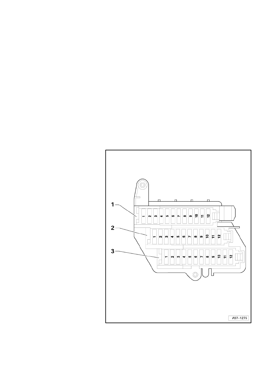
Location of fuses (SC), right dash panel
Fuse colours
40 A - orange
30 A - green
25 A - white
20 A - yellow
15 A - blue
10 A - red
7.5 A - brown
5 A - beige
3 A - purple
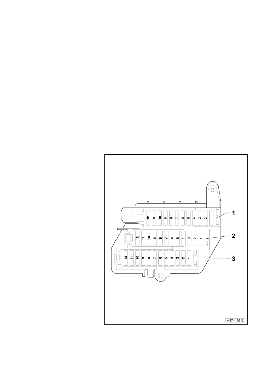
1 - Fuse carrier ST1 (black)
2 - Fuse carrier ST2 (brown)
3 - Fuse carrier ST3 (red)
Strona 39 z 77
WI-XML
2011-05-20
file://C:\ElsaWin\docs\slp\A\en-GB\A005A6200802.htm

Audi A6
Fitting Locations
No. 802 / 36
Position of fuses, fuse holder, from model year 2005
No. Current Flow Diagram
designation
Fuse carrier ST1 (black)
Nominal
value
Function/component
Terminal
1
- SC1 - Fuse 1 on fuse holder
5A¹)
15A²)
- R173
-
J723
-
Traffic data aerial¹)
Aerial reader unit for keyless entry
system²)
30
2
- SC2 - Fuse 2 on fuse holder
20A
- U1 -
Cigarette lighter
30
3
- SC3 - Fuse 3 on fuse holder
5A
- J502
-
Tyre pressure monitor control unit
30
4
- SC4 - Fuse 4 on fuse holder
20A
- U5 -
12 V socket
30
5
- SC5 - Fuse 5 on fuse holder
15A
- J520
-
Onboard supply control unit 2
30
6
- SC6 - Fuse 6 on fuse holder
15A
- J387
-
J389
-
Front passenger door control unit
Rear right door control unit
30
7
- SC7 - Fuse 7 on fuse holder
20A
- J245
-
Sliding sunroof adjustment control unit
30
8
- SC8 - Fuse 8 on fuse holder
10A
- J255
-
Climatronic control unit
30
9
- SC9 - Fuse 9 on fuse holder
30A
- J255
-
Climatronic control unit
30
10 - SC10 - Fuse 10 on fuse
holder
10A
5A
- J523
-
Front information display and operating
unit control unit
30
11 - SC11 - Fuse 11 on fuse
holder
15A
- J197
-
Adaptive suspension control unit
30
12 - SC12 - Fuse 12 on fuse
holder
5A
- R118
-
R119
-
Media player in position 1
Media player in position 2
30
¹) up to October 2005
²) from November 2005
Strona 40 z 77
WI-XML
2011-05-20
file://C:\ElsaWin\docs\slp\A\en-GB\A005A6200802.htm

Audi A6
Fitting Locations
No. 802 / 37
No. Current Flow Diagram
designation
Fuse carrier ST2 (brown)
Nominal
value
Function/component
Terminal
1
-
SC1 - Fuse 1 on fuse holder
20A
-
G23
-
G6 -
J538
Fuel pump (BMK, BNG)
Fuel pump (BBJ, BAT)
Fuel pump control unit (AUK)
87
2
- SC2 - Fuse 2 on fuse holder
10A
- U10
-
Trailer socket¹)
15
3
- Vacant
4
- Vacant
5
- SC5 - Fuse 5 on fuse holder
5A
- J197
-
Adaptive suspension control unit
15
6
- SC6 - Fuse 6 on fuse holder
5A
- J587
-
Selector lever sensors control unit
15
7
- SC7 - Fuse 7 on fuse holder
5A
- J446
-
Parking aid control unit
15
8
- SC8 - Fuse 8 on fuse holder
5A
- J533
-
Data bus diagnostic interface
15
9
- SC9 - Fuse 9 on fuse holder
5A
- J431
-
Headlight range control, control unit
15
10 - SC10 - Fuse 10 on fuse
holder
5A
- J234
-
K145
-
Airbag control unit
Front passenger side airbag deactivated
warning lamp
15
11 - SC11 - Fuse 11 on fuse
holder
5A
- E128
-
E129
-
Heated rear left seat switch with
regulator
Heated rear right seat switch with
regulator
15
12 - Vacant
¹) no longer fitted, phased from October 2004
Strona 41 z 77
WI-XML
2011-05-20
file://C:\ElsaWin\docs\slp\A\en-GB\A005A6200802.htm

Audi A6
Fitting Locations
No. 802 / 38
No. Current Flow Diagram
designation
Fuse carrier ST3 (red)
Nominal
value
Function/component
Terminal
1
- SC1 - Fuse 1 on fuse holder
25A
- J615
-
Signal system operating unit control unit
30
2
- SC2 - Fuse 2 on fuse holder
15A
- J615
-
Signal system operating unit control unit
30
3
- SC3 - Fuse 3 on fuse holder
15A
- J615
-
Signal system operating unit control unit
30
4
-
SC4 - Fuse 4 on fuse holder
5A
10A
10A
10A
-
G41
-
G24
-
J608
-
J615
-
Taxi meter
Tachograph
Special vehicle control unit
Signal system operating unit control unit
15
5
-
SC5 - Fuse 5 on fuse holder
10A
15A
25A
-
J608
-
J608
-
J608
-
Special vehicle control unit
Special vehicle control unit
Special vehicle control unit
30
6
- SC6 - Fuse 6 on fuse holder
5A
10A
15A
- J608
-
R8 -
T5i -
Special vehicle control unit
Two-way radio
Connector for optional equipment
30
7
- SC7 - Fuse 7 on fuse holder
5A
10A
25A
- G41
-
G24
-
J476
-
Taxi meter
Tachograph
Personal danger alarm control unit
30
8
- SC8 - Fuse 8 on fuse holder
20A
10A
15A
- U5 -
U19
-
T4ag
-
12 V socket
12 V socket 3
Connector for optional equipment
30
9
- SC9 - Fuse 9 on fuse holder
15A
- T5k - Connector for optional equipment
30
10 - Vacant
11 - Vacant
12 - Vacant
Strona 42 z 77
WI-XML
2011-05-20
file://C:\ElsaWin\docs\slp\A\en-GB\A005A6200802.htm

Audi A6
Fitting Locations
No. 802 / 39
Position of fuses, fuse holder, left-hand drive, from model year 2007
No. Current Flow Diagram designation
Fuse carrier ST1 (black)
Nominal
value
Function/component
Terminal
1
- SC1 - Fuse 1 on fuse holder C
15 A
- J723 - Aerial reader
unit for keyless entry
system
30
2
- SC2 - Fuse 2 on fuse holder C
20 A
- U1 - Cigarette lighter
30
3
- SC3 - Fuse 3 on fuse holder C
5 A
- J502 - Tyre pressure
monitor control unit
30
4
- SC4 - Fuse 4 on fuse holder C
20 A
- U5 - 12 V socket
(USA)
30
5
- SC5-Fuse 5 on fuse holder C
15 A
- J520 - Onboard supply
control unit 2
30
6
- SC6 - Fuse 6 on fuse holder C
15 A
- J387 - Front
passenger side door
control unit
J389 - Rear right door
control unit
30
7
- SC7 - Fuse 7 on fuse holder C
20 A
- J245 - Sliding sunroof
adjustment control unit
30
8
- SC8 - Fuse 8 on fuse holder C
10 A
- J255 - Climatronic
control unit
30
9
- SC9 - Fuse 9 on fuse holder C
30 A
- J255 - Climatronic
control unit
Z45 - Front left seat
heating
Z46 - Front right seat
heating
30
10 - SC10 - Fuse 10 on fuse holder C
10 A¹)
5 A
- J523 - Front
information display and
operating unit control
unit
30
11 - SC11 - Fuse 11 on fuse holder C
10 A
- Seat adjustment
lumbar support front
passenger seat
30
12 - SC12 - Fuse 12 on fuse holder C
5 A
- R118 - Media player in
position 1
R119 - Media player in
position 2 (up to
October 2006)
R199 - Connection for
external audio source
(from November 2006)
30
¹) MMI Basic
Strona 43 z 77
WI-XML
2011-05-20
file://C:\ElsaWin\docs\slp\A\en-GB\A005A6200802.htm

Audi A6
Fitting Locations
No. 802 / 40
No. Current Flow Diagram designation
Fuse carrier ST2 (brown)
Nominal
value
Function/component
Terminal
1
- SC1 - Fuse 1 on fuse holder C
20 A
30 A
- G23 - Fuel pump
(BMK, BNG)
G6 - Fuel pump (BBJ,
BAT)
J538 - Fuel pump
control unit (AUK, BVJ,
BXA, BDX)
87
2
- SC2 - Fuse 2 on fuse holder C
15 A
- J197 - Adaptive
suspension control unit
30
3
- SC3 - Fuse 3 on fuse holder C
10 A
- J759 - Lane departure
warning control unit
15
4
- Vacant
5
- SC5-Fuse 5 on fuse holder C
5 A
- J197 - Adaptive
suspension control unit
15
6
- SC6 - Fuse 6 on fuse holder C
5 A
- J587 - Selector lever
sensors control unit
F47 - Brake pedal
switch
15
7
- SC7 - Fuse 7 on fuse holder C
5 A
- J446 - Parking aid
control unit
15
8
- SC8 - Fuse 8 on fuse holder C
5 A
- J533 - Data bus
diagnostic interface
15
9
- SC9 - Fuse 9 on fuse holder C
5 A
- Right headlight
J431 - Headlight range
control, control unit
J745 - Cornering light
and headlight range
control unit
15
10 - SC10 - Fuse 10 on fuse holder C
5 A
- J234 - Airbag control
unit
15
11 - SC11 - Fuse 11 on fuse holder C
5 A
- E128 - Heated rear left
seat switch with
regulator
E129 - Heated rear
right seat switch with
regulator
15
12 - SC12 - Fuse 12 on fuse holder C
5 A
- Preparation for mobile
telephone
15
Strona 44 z 77
WI-XML
2011-05-20
file://C:\ElsaWin\docs\slp\A\en-GB\A005A6200802.htm

Audi A6
Fitting Locations
No. 802 / 41
No. Current Flow Diagram designation
Fuse carrier ST3 (red)
Nominal
value
Function/component
Terminal
1
- SC1 - Fuse 1 on fuse holder C
25 A
- J615 - Signal system
operating unit control
unit
30
2
- SC2 - Fuse 2 on fuse holder C
15 A
- J615 - Signal system
operating unit control
unit
30
3
- SC3 - Fuse 3 on fuse holder C
15 A
- J615 - Signal system
operating unit control
unit
30
4
- SC4 - Fuse 4 on fuse holder C
5 A
10 A
10 A
10 A
- G41 - Taxi meter
G24 - Tachograph
J608 - Special vehicle
control unit
J615 - Signal system
operating unit control
unit
15
5
- SC5-Fuse 5 on fuse holder C
10 A
15 A
25 A
- J608 - Special vehicle
control unit
J608 - Special vehicle
control unit
J608 - Special vehicle
control unit
30
6
- SC6 - Fuse 6 on fuse holder C
5 A
10 A
15 A
- J608 - Special vehicle
control unit
R8 - Two-way radio
T5i - Connector for
optional equipment
30
7
- SC7 - Fuse 7 on fuse holder C
5 A
10 A
15 A
- G41 - Taxi meter
G24 - Tachograph
J476 - Personal
danger alarm control
unit
30
8
- SC8 - Fuse 8 on fuse holder C
20 A
10 A
15 A
- U5 - 12 V socket
U19 - 12 V socket 3
T4ag - Connector for
optional equipment
30
9
- SC9 - Fuse 9 on fuse holder C
15 A
- T5k - Connector for
optional equipment
30
10 - Vacant
11 - Vacant
12 - Vacant
Strona 45 z 77
WI-XML
2011-05-20
file://C:\ElsaWin\docs\slp\A\en-GB\A005A6200802.htm

Audi A6
Fitting Locations
No. 802 / 42
Position of fuses, fuse holder, left-hand drive, from model year 2009
No. Current Flow Diagram designation
Fuse carrier ST1 (black)
Nominal
value
Function/component
Terminal
1
- SC1 - Fuse 1 on fuse holder C
15 A
- J723 - Aerial reader
unit for keyless entry
system
30
2
- SC2 - Fuse 2 on fuse holder C
20 A
- U1 - Cigarette lighter
30
3
- SC3 - Fuse 3 on fuse holder C
5 A
- J502 - Tyre pressure
monitor control unit
30
4
- SC4 - Fuse 4 on fuse holder C
20 A
- U5 - 12 V socket
(USA)
30
5
- SC5-Fuse 5 on fuse holder C
15 A
- J520 - Onboard supply
control unit 2
30
6
- SC6 - Fuse 6 on fuse holder C
15 A
- J387 - Front
passenger side door
control unit
J389 - Rear right door
control unit
30
7
- SC7 - Fuse 7 on fuse holder C
20 A
- J245 - Sliding sunroof
adjustment control unit
30
8
- SC8 - Fuse 8 on fuse holder C
10 A
- J255 - Climatronic
control unit
30
9
- SC9 - Fuse 9 on fuse holder C
30 A
- J255 - Climatronic
control unit
Z45 - Front left seat
heating
Z46 - Front right seat
heating
30
10 - SC10 - Fuse 10 on fuse holder C
7,5 A
- J794 - Control unit for
information electronics
1
30
11 - SC11 - Fuse 11 on fuse holder C
10 A
- Seat adjustment
lumbar support front
passenger seat
30
12 - SC12 - Fuse 12 on fuse holder C
5 A
- R7 - DVD player
R41 - CD changer
30
Strona 46 z 77
WI-XML
2011-05-20
file://C:\ElsaWin\docs\slp\A\en-GB\A005A6200802.htm

Audi A6
Fitting Locations
No. 802 / 43
No. Current Flow Diagram designation
Fuse carrier ST2 (brown)
Nominal
value
Function/component
Terminal
1
- SC1 - Fuse 1 on fuse holder C
20 A
30 A
- G23 - Fuel pump
G6 - Fuel pump
J538 - Fuel pump
control unit
87
2
- SC2 - Fuse 2 on fuse holder C
15 A
- J197 - Adaptive
suspension control unit
30
3
- SC3 - Fuse 3 on fuse holder C
10 A
- J759 - Lane departure
warning control unit
15
4
- SC4 - Fuse 4 on fuse holder C
5 A
- J769 - Lane change
assist control unit
15
5
- SC5-Fuse 5 on fuse holder C
5 A
- J197 - Adaptive
suspension control unit
15
6
- SC6 - Fuse 6 on fuse holder C
5 A
- J587 - Selector lever
sensors control unit
F47 - Brake pedal
switch
15
7
- SC7 - Fuse 7 on fuse holder C
5 A
- J446 - Parking aid
control unit
15
8
- SC8 - Fuse 8 on fuse holder C
5 A
- J533 - Data bus
diagnostic interface
15
9
- SC9 - Fuse 9 on fuse holder C
5 A
- Right headlight
J431 - Headlight range
control, control unit
J745 - Cornering light
and headlight range
control unit
15
10 - SC10 - Fuse 10 on fuse holder C
5 A
- J234 - Airbag control
unit
15
11 - SC11 - Fuse 11 on fuse holder C
5 A
- E128 - Heated rear left
seat switch with
regulator
E129 - Heated rear
right seat switch with
regulator
15
12 - SC12 - Fuse 12 on fuse holder C
5 A
- Preparation for mobile
telephone
15
Strona 47 z 77
WI-XML
2011-05-20
file://C:\ElsaWin\docs\slp\A\en-GB\A005A6200802.htm

Audi A6
Fitting Locations
No. 802 / 44
No. Current Flow Diagram designation
Fuse carrier ST3 (red)
Nominal
value
Function/component
Terminal
1
- SC1 - Fuse 1 on fuse holder C
25 A
- J615 - Signal system
operating unit control
unit
30
2
- SC2 - Fuse 2 on fuse holder C
15 A
- J615 - Signal system
operating unit control
unit
30
3
- SC3 - Fuse 3 on fuse holder C
15 A
- J615 - Signal system
operating unit control
unit
30
4
- SC4 - Fuse 4 on fuse holder C
5 A
10 A
10 A
10 A
- G41 - Taxi meter
G24 - Tachograph
J608 - Special vehicle
control unit
J615 - Signal system
operating unit control
unit
15
5
- SC5-Fuse 5 on fuse holder C
10 A
15 A
25 A
- J608 - Special vehicle
control unit
J608 - Special vehicle
control unit
J608 - Special vehicle
control unit
30
6
- SC6 - Fuse 6 on fuse holder C
5 A
10 A
15 A
- J608 - Special vehicle
control unit
R8 - Two-way radio
T5i - Connector for
optional equipment
30
7
- SC7 - Fuse 7 on fuse holder C
5 A
10 A
15 A
- G41 - Taxi meter
G24 - Tachograph
J476 - Personal
danger alarm control
unit
30
8
- SC8 - Fuse 8 on fuse holder C
20 A
10 A
15 A
- U5 - 12 V socket
U19 - 12 V socket 3
T4ag - Connector for
optional equipment
30
9
- SC9 - Fuse 9 on fuse holder C
15 A
- T5k - Connector for
optional equipment
30
10 - Vacant
11 - Vacant
12 - Vacant
Strona 48 z 77
WI-XML
2011-05-20
file://C:\ElsaWin\docs\slp\A\en-GB\A005A6200802.htm
Audi A6
Fitting Locations
No. 802 / 45
Location of fuses (SC), left dash panel, right-
hand drive
Fuse colours
40 A - orange
30 A - green
25 A - white
20 A - yellow
15 A - blue
10 A - red
7.5 A - brown
5 A - beige
3 A - purple
1 - Fuse carrier ST1 (black)
2 - Fuse carrier ST2 (brown)
3 - Fuse carrier ST3 (red)
Strona 49 z 77
WI-XML
2011-05-20
file://C:\ElsaWin\docs\slp\A\en-GB\A005A6200802.htm

Audi A6
Fitting Locations
No. 802 / 46
Position of fuses, fuse holder, right-hand drive, from model year 2007
No. Current Flow Diagram designation
Fuse carrier ST1 (black)
Nominal
value
Function/component
Terminal
1
- Vacant
2
- SC2 - Fuse 2 on fuse holder C
15 A
- J723 - Aerial reader
unit for keyless entry
system
30
3
- SC3 - Fuse 3 on fuse holder C
5 A
- J502 - Tyre pressure
monitor control unit
30
4
- SC4 - Fuse 4 on fuse holder C
10 A
- Seat adjustment
lumbar support front
passenger seat
30
5
- SC5-Fuse 5 on fuse holder C
15 A
- J520 - Onboard supply
control unit 2
30
6
- SC6 - Fuse 6 on fuse holder C
15 A
- J387 - Front
passenger side door
control unit
J389 - Rear right door
control unit
30
7
- SC7 - Fuse 7 on fuse holder C
20 A
- J245 - Sliding sunroof
adjustment control unit
30
8
- SC8 - Fuse 8 on fuse holder C
35 A
- V26 - Rear left window
regulator motor
V147 - Driver side
window regulator
motor
30
9
- Vacant
10 - SC10 - Fuse 10 on fuse holder C
10 A¹)
5 A
- J523 - Front
information display and
operating unit control
unit
30
11 - SC11 - Fuse 11 on fuse holder C
15 A
- J197 - Adaptive
suspension control unit
30
12 - SC12 - Fuse 12 on fuse holder C
5 A
- R118 - Media player in
position 1
R119 - Media player in
position 2 (up to
October 2006)
R199 - Connection for
external audio source
(from November 2006)
30
¹) MMI Basic
Strona 50 z 77
WI-XML
2011-05-20
file://C:\ElsaWin\docs\slp\A\en-GB\A005A6200802.htm

Audi A6
Fitting Locations
No. 802 / 47
No. Current Flow Diagram designation
Fuse carrier ST2 (brown)
Nominal
value
Function/component
Terminal
1
- SC1 - Fuse 1 on fuse holder C
20 A
30 A
- G23 - Fuel pump
(BMK, BNG)
G6 - Fuel pump (BBJ,
BAT)
J538 - Fuel pump
control unit (AUK, BVJ,
BXA, BDX)
87
2
- Vacant
3
- SC3 - Fuse 3 on fuse holder C
5 A
- J530 - Garage door
operation control unit
15
4
- SC4 - Fuse 4 on fuse holder C
5 A
- J428 - Adaptive cruise
control unit
15
5
- SC5-Fuse 5 on fuse holder C
5 A
- J197 - Adaptive
suspension control unit
15
6
- SC6 - Fuse 6 on fuse holder C
5 A
- J623 - Engine control
unit
15
7
- SC7 - Fuse 7 on fuse holder C
5 A
- G226 - Oil level and oil
temperature sender
15
8
- SC8 - Fuse 8 on fuse holder C
5 A
- J533 - Data bus
diagnostic interface
15
9
- SC9 - Fuse 9 on fuse holder C
5 A
- Left headlight
J431 - Headlight range
control, control unit
J745 - Cornering light
and headlight range
control unit
15
10 - SC10 - Fuse 10 on fuse holder C
5 A
- J104 - ABS control unit
G476 - Clutch position
sender
15
11 - SC11 - Fuse 11 on fuse holder C
5 A
- Y7 - Automatic anti-
dazzle interior mirror
15
12 - SC12 - Fuse 12 on fuse holder C
15 A
- F4 - Reversing light
switch
G70 - Air mass meter
(TDI)
J217 - Automatic
gearbox control unit
15
Strona 51 z 77
WI-XML
2011-05-20
file://C:\ElsaWin\docs\slp\A\en-GB\A005A6200802.htm

Audi A6
Fitting Locations
No. 802 / 48
No. Current Flow Diagram designation
Fuse carrier ST3 (red)
Nominal
value
Function/component
Terminal
1
- Vacant
2
- SC2 - Fuse 2 on fuse holder C
5 A
- G397 - Rain and light
detector sensor
30
3
- SC3 - Fuse 3 on fuse holder C
20 A
- J364 - Auxiliary heater
control unit
30
4
- SC4 - Fuse 4 on fuse holder C
5 A
- R64 - Remote control
receiver for auxiliary
heating
30
5
- SC5-Fuse 5 on fuse holder C
30 A
- J39 - Headlight washer
system relay
30
6
- SC6 - Fuse 6 on fuse holder C
25 A
- J608 - Special vehicle
control unit
30
7
- SC7 - Fuse 7 on fuse holder C
10 A
- R36 - Telephone
transmitter and
receiver unit
30
8
- SC8 - Fuse 8 on fuse holder C
25 A
- J4 - Dual tone horn
relay
H2 - Treble tone horn
H7 - Bass tone horn
30
9
- SC9 - Fuse 9 on fuse holder C
15 A
- J476 - Personal
danger alarm control
unit
30
10 - SC10 - Fuse 10 on fuse holder C
15 A
- T4ag - Connector for
optional equipment
30
11 - Vacant
12 - Vacant
Strona 52 z 77
WI-XML
2011-05-20
file://C:\ElsaWin\docs\slp\A\en-GB\A005A6200802.htm

Audi A6
Fitting Locations
No. 802 / 49
Position of fuses, fuse holder, right-hand drive, from model year 2009
No. Current Flow Diagram designation
Fuse carrier ST1 (black)
Nominal
value
Function/component
Terminal
1
- Vacant
2
- SC2 - Fuse 2 on fuse holder C
15 A
- J723 - Aerial reader
unit for keyless entry
system
30
3
- SC3 - Fuse 3 on fuse holder C
5 A
- J502 - Tyre pressure
monitor control unit
30
4
- SC4 - Fuse 4 on fuse holder C
10 A
- Seat adjustment
lumbar support front
passenger seat
30
5
- SC5-Fuse 5 on fuse holder C
15 A
- J520 - Onboard supply
control unit 2
30
6
- SC6 - Fuse 6 on fuse holder C
15 A
- J387 - Front
passenger side door
control unit
J389 - Rear right door
control unit
30
7
- SC7 - Fuse 7 on fuse holder C
20 A
- J245 - Sliding sunroof
adjustment control unit
30
8
- SC8 - Fuse 8 on fuse holder C
35 A
- V26 - Rear left window
regulator motor
V147 - Driver side
window regulator
motor
30
9
- Vacant
10 - SC10 - Fuse 10 on fuse holder C
7,5 A
- J794 - Control unit for
information electronics
1
30
11 - SC11 - Fuse 11 on fuse holder C
15 A
- J197 - Adaptive
suspension control unit
30
12 - SC12 - Fuse 12 on fuse holder C
5 A
- R7 - DVD player
R41 - CD changer
30
Strona 53 z 77
WI-XML
2011-05-20
file://C:\ElsaWin\docs\slp\A\en-GB\A005A6200802.htm

Audi A6
Fitting Locations
No. 802 / 50
No. Current Flow Diagram designation
Fuse carrier ST2 (brown)
Nominal
value
Function/component
Terminal
1
- SC1 - Fuse 1 on fuse holder C
20 A
30 A
- G23 - Fuel pump
G6 - Fuel pump
J538 - Fuel pump
control unit
87
2
- SC2 - Fuse 2 on fuse holder C
5 A
- J769 - Lane change
assist control unit
15
3
- SC3 - Fuse 3 on fuse holder C
5 A
- J530 - Garage door
operation control unit
15
4
- SC4 - Fuse 4 on fuse holder C
5 A
- J428 - Adaptive cruise
control unit
15
5
- SC5-Fuse 5 on fuse holder C
5 A
- J197 - Adaptive
suspension control unit
15
6
- SC6 - Fuse 6 on fuse holder C
5 A
- J623 - Engine control
unit
15
7
- SC7 - Fuse 7 on fuse holder C
5 A
- G226 - Oil level and oil
temperature sender
15
8
- SC8 - Fuse 8 on fuse holder C
5 A
- J533 - Data bus
diagnostic interface
15
9
- SC9 - Fuse 9 on fuse holder C
5 A
- Left headlight
J431 - Headlight range
control, control unit
J745 - Cornering light
and headlight range
control unit
15
10 - SC10 - Fuse 10 on fuse holder C
5 A
- J104 - ABS control unit
G476 - Clutch position
sender
15
11 - SC11 - Fuse 11 on fuse holder C
5 A
- Y7 - Automatic anti-
dazzle interior mirror
15
12 - SC12 - Fuse 12 on fuse holder C
15 A
- F4 - Reversing light
switch
G70 - Air mass meter
(TDI)
J217 - Automatic
gearbox control unit
15
Strona 54 z 77
WI-XML
2011-05-20
file://C:\ElsaWin\docs\slp\A\en-GB\A005A6200802.htm

Audi A6
Fitting Locations
No. 802 / 51
No. Current Flow Diagram designation
Fuse carrier ST3 (red)
Nominal
value
Function/component
Terminal
1
- Vacant
2
- SC2 - Fuse 2 on fuse holder C
5 A
- G397 - Rain and light
detector sensor
30
3
- SC3 - Fuse 3 on fuse holder C
20 A
- J364 - Auxiliary heater
control unit
30
4
- SC4 - Fuse 4 on fuse holder C
5 A
- R64 - Remote control
receiver for auxiliary
heating
30
5
- SC5-Fuse 5 on fuse holder C
30 A
- J39 - Headlight washer
system relay
30
6
- SC6 - Fuse 6 on fuse holder C
25 A
- J608 - Special vehicle
control unit
30
7
- SC7 - Fuse 7 on fuse holder C
5 A
- J794 - Control unit for
information electronics
1
R126 - Telephone
bracket
30
8
- SC8 - Fuse 8 on fuse holder C
25 A
- J4 - Dual tone horn
relay
H2 - Treble tone horn
H7 - Bass tone horn
30
9
- SC9 - Fuse 9 on fuse holder C
15 A
- J476 - Personal
danger alarm control
unit
30
10 - SC10 - Fuse 10 on fuse holder C
15 A
- T4ag - Connector for
optional equipment
30
11 - Vacant
12 - Vacant
Strona 55 z 77
WI-XML
2011-05-20
file://C:\ElsaWin\docs\slp\A\en-GB\A005A6200802.htm
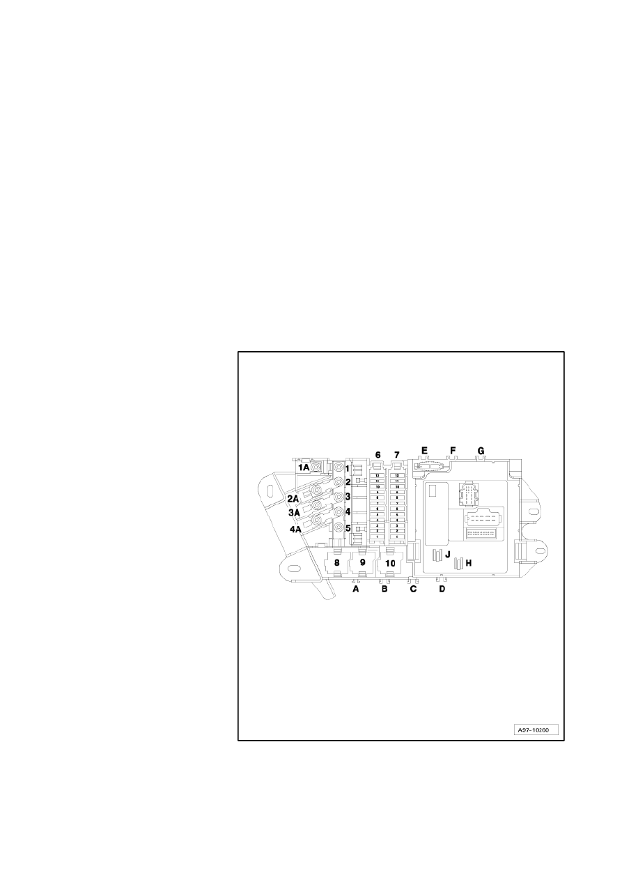
Audi A6
Fitting Locations
No. 802 / 52
Location of fuses (SF) on right in luggage
compartment
Fuse colours
40 A - orange
30 A - green
25 A - white
20 A - yellow
15 A - blue
10 A - red
7.5 A - brown
5 A - beige
3 A - purple
6 - Fuse carrier ST1 (black)
7 - Fuse carrier ST2 (brown)
Strona 56 z 77
WI-XML
2011-05-20
file://C:\ElsaWin\docs\slp\A\en-GB\A005A6200802.htm

Audi A6
Fitting Locations
No. 802 / 53
Position of fuses, fuse holder, from model year 2005
No. Current Flow Diagram
designation
Fuse carrier ST1 (black)
Nominal
value
Function/component
Terminal
1
- SF1 - Fuse 1 on fuse holder
20A
- J749
-
Fuel pump relay for auxiliary heater
30
2
- Vacant
3
- SF3 - Fuse 3 on fuse holder
30A
- J540
-
Electric park and handbrake control unit
30
4
- SF4 - Fuse 4 on fuse holder
30A
- J540 Electric park and handbrake control unit
30
5
- SF5 - Fuse 5 on fuse holder
20A
- U18
-
12 V socket 2
30
6
- SF6 - Fuse 6 on fuse holder
5A
- J644
-
Energy management control unit
30
7
- SF7 - Fuse 7 on fuse holder
20A
- J393
-
Convenience system central control unit
30
8
- SF8 - Fuse 8 on fuse holder
5A
- J529
-
Anti-theft and tilt system control unit
30
9
- SF9 - Fuse 9 on fuse holder
30A
- J393
-
Convenience system central control unit
30
10 - SF10 - Fuse 10 on fuse
holder
35A
- V27
-
V148
-
Rear right window regulator motor¹)
Front passenger side window regulator
motor¹)
30
11 - SF11 - Fuse 11 on fuse
holder
10A
20A
- J446
-
U1 -
Parking aid control unit
Cigarette lighter (right-hand drive)
30
12 - SF12 - Fuse 12 on fuse
holder
20A
- U9 -
Rear cigarette lighter
30
¹) from November 2005
Strona 57 z 77
WI-XML
2011-05-20
file://C:\ElsaWin\docs\slp\A\en-GB\A005A6200802.htm

Audi A6
Fitting Locations
No. 802 / 54
No. Current Flow Diagram
designation
Fuse carrier ST2 (brown)
Nominal
value
Function/component
Terminal
1
- Vacant
2
- SF2 - Fuse 2 on fuse holder
30A
- J605
-
Rear lid control unit
30
3
- SF3 - Fuse 3 on fuse holder
30A
- J756
-
Rear lid control unit 2
30
4
- SF4 - Fuse 4 on fuse holder
20A
- J657
-
Power latching control unit
30
5
- SF5 - Fuse 5 on fuse holder
5A
- R -
Radio
30
6
- SF6 - Fuse 6 on fuse holder
5A
- R78
-
TV tuner
30
7
- SF7 - Fuse 7 on fuse holder
5A
- J401
-
Navigation system with CD drive control
unit
30
8
- SF8 - Fuse 8 on fuse holder
30A
- J525
-
Digital sound package control unit
30
9
- SF9 - Fuse 9 on fuse holder
5A
- R147
-
Digital radio
30
10 - SF10 - Fuse 10 on fuse
holder
15A
- J345
-
Trailer detector control unit
30
11 - SF11 - Fuse 11 on fuse
holder
15A
- J345
-
Trailer detector control unit
30
12 - SF12 - Fuse 12 on fuse
holder
15A
- J345
-
Trailer detector control unit
30
Strona 58 z 77
WI-XML
2011-05-20
file://C:\ElsaWin\docs\slp\A\en-GB\A005A6200802.htm

Audi A6
Fitting Locations
No. 802 / 55
Position of fuses, fuse holder, from model year 2007
No. Current Flow Diagram designation
Fuse carrier ST1 (black)
Nominal
value
Function/component
Terminal
1
- SF1 - Fuse 1 on fuse holder F
30 A
- J525 - Digital sound
package control unit
30
2
- SF2 - Fuse 2 on fuse holder F
5 A
- R - Radio
R24 - Aerial amplifier
30
3
- SF3 - Fuse 3 on fuse holder F
30 A
- J540 - Electric park
and handbrake control
unit
30
4
- SF4 - Fuse 4 on fuse holder F
30 A
- J540 - Electric park
and handbrake control
unit
30
5
- SF5 - Fuse 5 on fuse holder F
20 A
- U18 - 12 V socket -2-
30
6
- SF6 - Fuse 6 on fuse holder F
5 A
- J644 - Energy
management control
unit
30
7
- SF7 - Fuse 7 on fuse holder F
20 A
- J393 - Convenience
system central control
unit
30
8
- SF8 - Fuse 8 on fuse holder F
5 A
- J401 - Navigation
system with CD drive
control unit
30
9
- SF9 - Fuse 9 on fuse holder F
30 A
- J393 - Convenience
system central control
unit
30
10 - SF10 - Fuse 10 on fuse holder F
35 A
- V27 - Rear right
window regulator
motor
V148 - Front
passenger side
window regulator
motor
30
11 - SF11 - Fuse 11 on fuse holder F
10 A
5 A¹)
20 A
- J446 - Parking aid
control unit
U1 - Cigarette lighter
(right-hand drive only)
30
12 - SF12 - Fuse 12 on fuse holder F
20 A
- U9 - Rear cigarette
lighter
30
¹) from June 2007
Strona 59 z 77
WI-XML
2011-05-20
file://C:\ElsaWin\docs\slp\A\en-GB\A005A6200802.htm

Audi A6
Fitting Locations
No. 802 / 56
No. Current Flow Diagram designation
Fuse carrier ST2 (brown)
Nominal
value
Function/component
Terminal
1
- SF1 - Fuse 1 on fuse holder F
5 A
- J772 - Reversing
camera system control
unit
30
2
- SF2 - Fuse 2 on fuse holder F
30 A
- J605 - Rear lid control
unit
30
3
- SF3 - Fuse 3 on fuse holder F
30 A
- J756 - Rear lid control
unit 2
30
4
- SF4 - Fuse 4 on fuse holder F
20 A
- J657 - Power latching
control unit
30
5
- Vacant
6
- SF6 - Fuse 6 on fuse holder F
5 A
- R78 - TV tuner
30
7
- SF7 - Fuse 7 on fuse holder F
5 A
- J393 - Convenience
system central control
unit
30
8
- SF8 - Fuse 8 on fuse holder F
20 A
- J749 - Fuel pump relay
for auxiliary heater
30
9
- SF9 - Fuse 9 on fuse holder F
5 A
- R147 - Digital radio
30
10 - SF10 - Fuse 10 on fuse holder F
15 A
- J345 - Trailer detector
control unit
30
11 - SF11 - Fuse 11 on fuse holder F
15 A
- J345 - Trailer detector
control unit
30
12 - SF12 - Fuse 12 on fuse holder F
15 A
- J345 - Trailer detector
control unit
30
Strona 60 z 77
WI-XML
2011-05-20
file://C:\ElsaWin\docs\slp\A\en-GB\A005A6200802.htm

Audi A6
Fitting Locations
No. 802 / 57
Position of fuses, fuse holder, from model year 2009
No. Current Flow Diagram designation
Fuse carrier ST1 (black)
Nominal
value
Function/component
Terminal
1
- SF1 - Fuse 1 on fuse holder F
30 A
- J525 - Digital sound
package control unit
R - Radio²)
30
2
- SF2 - Fuse 2 on fuse holder F
5 A
- R - Radio¹)
30
3
- SF3 - Fuse 3 on fuse holder F
30 A
- J540 - Electric park
and handbrake control
unit
30
4
- SF4 - Fuse 4 on fuse holder F
30 A
- J540 - Electric park
and handbrake control
unit
30
5
- SF5 - Fuse 5 on fuse holder F
20 A
- U18 - 12 V socket -2-
30
6
- SF6 - Fuse 6 on fuse holder F
5 A
- J644 - Energy
management control
unit
30
7
- SF7 - Fuse 7 on fuse holder F
20 A
- J393 - Convenience
system central control
unit
30
8
- SF8 - Fuse 8 on fuse holder F
5 A
- G273 - Interior
monitoring sensor
H12 - Alarm horn
30
9
- SF9 - Fuse 9 on fuse holder F
30 A
- J393 - Convenience
system central control
unit
30
10 - SF10 - Fuse 10 on fuse holder F
35 A
- V27 - Rear right
window regulator
motor
V148 - Front
passenger side
window regulator
motor
30
11 - SF11 - Fuse 11 on fuse holder F
5 A
20 A
- J446 - Parking aid
control unit
U1 - Cigarette lighter
(right-hand drive only)
30
12 - SF12 - Fuse 12 on fuse holder F
20 A
- U9 - Rear cigarette
lighter
30
¹) models with BOSE soundsystem
²) models with soundsystem standard
Strona 61 z 77
WI-XML
2011-05-20
file://C:\ElsaWin\docs\slp\A\en-GB\A005A6200802.htm

Audi A6
Fitting Locations
No. 802 / 58
No. Current Flow Diagram designation
Fuse carrier ST2 (brown)
Nominal
value
Function/component
Terminal
1
- SF1 - Fuse 1 on fuse holder F
5 A
- J772 - Reversing
camera system control
unit
30
2
- SF2 - Fuse 2 on fuse holder F
30 A
- J605 - Rear lid control
unit
30
3
- SF3 - Fuse 3 on fuse holder F
30 A
- J756 - Rear lid control
unit 2
30
4
- SF4 - Fuse 4 on fuse holder F
20 A
- J657 - Power latching
control unit
30
5
- SF5 - Fuse 5 on fuse holder F
5 A
- Interface for special
functions:
30
6
- SF6 - Fuse 6 on fuse holder F
5 A
- R78 - TV tuner
30
7
- SF7 - Fuse 7 on fuse holder F
5 A
- J393 - Convenience
system central control
unit
30
8
- SF8 - Fuse 8 on fuse holder F
20 A
- J749 - Fuel pump relay
for auxiliary heater
30
9
- Vacant
10 - SF10 - Fuse 10 on fuse holder F
15 A
- J345 - Trailer detector
control unit
30
11 - SF11 - Fuse 11 on fuse holder F
20 A
- J345 - Trailer detector
control unit
30
12 - SF12 - Fuse 12 on fuse holder F
20 A
- J345 - Trailer detector
control unit
30
Strona 62 z 77
WI-XML
2011-05-20
file://C:\ElsaWin\docs\slp\A\en-GB\A005A6200802.htm
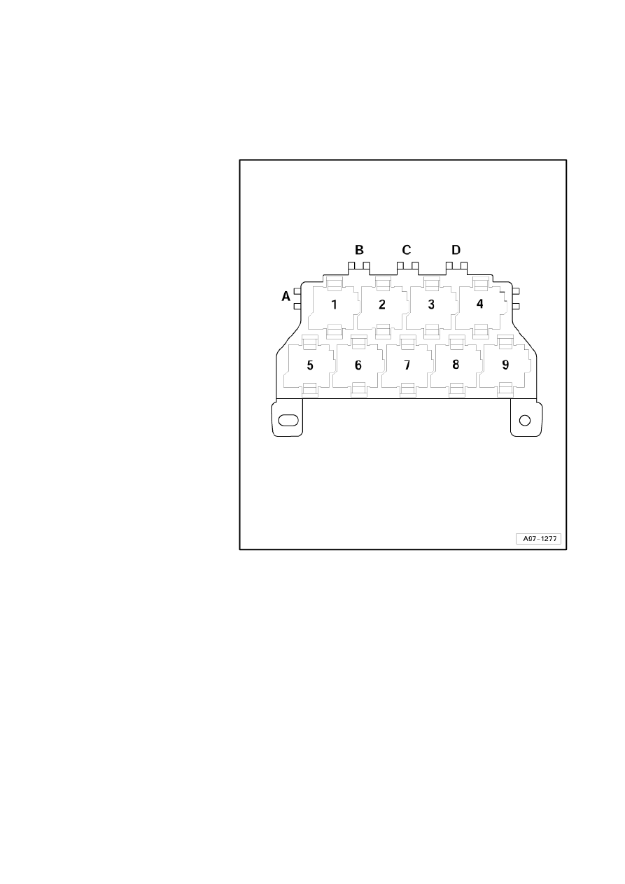
Audi A6
Fitting Locations
No. 802 / 59
Fuses behind driver's storage compartment
Position of fuses, fuse holder, from model year 2005
A - ABS control unit fuse 1 -
S123 (40A)
B - Vacant
C - Vacant
D - Vacant
Strona 63 z 77
WI-XML
2011-05-20
file://C:\ElsaWin\docs\slp\A\en-GB\A005A6200802.htm
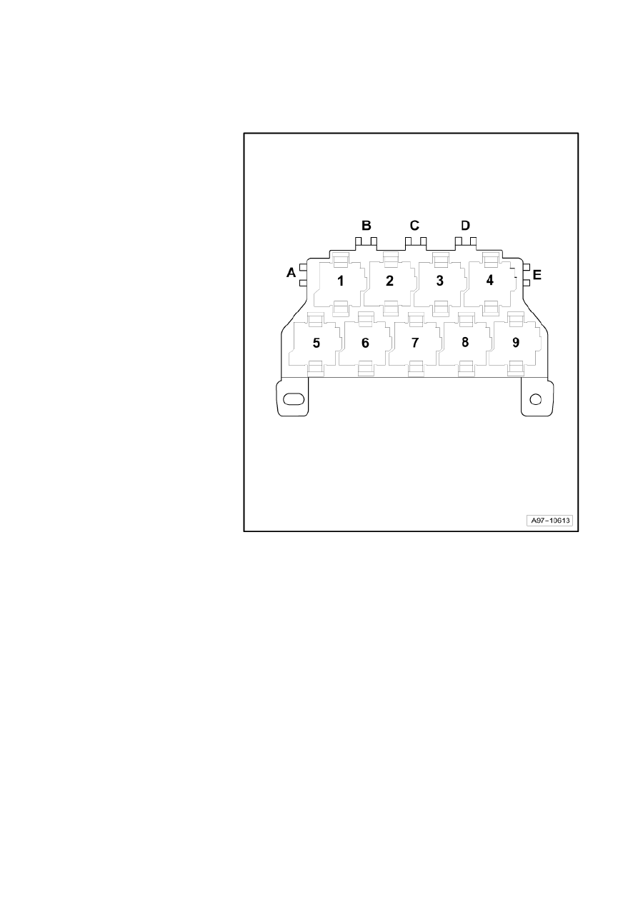
Audi A6
Fitting Locations
No. 802 / 60
Position of fuses, fuse holder, left-hand drive, from model year 2007
A - ABS control unit fuse 1 -
S123- (40 A)
B - Vacant
C - Driver seat adjustment
thermal fuse 1 -S44- (30 A)
D - Vacant (up to August
2008)
- Communications fuse -
S254- (5 A) (from
September 2008)
E - Vacant
Position of fuses, fuse
holder, right-hand drive,
from model year 2007
A - Vacant
B - Vacant (up to August
2008)
- Communications fuse -
S254- (5 A) (from
September 2008)
C - Driver seat adjustment
thermal fuse 1 -S44- (30 A)
D - Vacant
E - ABS control unit fuse 1 -
S123- (40 A)
Strona 64 z 77
WI-XML
2011-05-20
file://C:\ElsaWin\docs\slp\A\en-GB\A005A6200802.htm
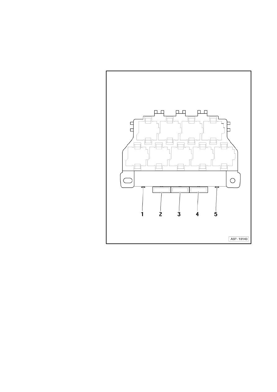
Audi A6
Fitting Locations
No. 802 / 61
Fuses on onboard supply control unit -J519-
Position of fuses, fuse holder
1 - Vacant
2 - Window regulator single
fuse 2 -S280- (30A)
up to October 2005
2 - Heater element fuse 1 -
S276- (40 A)
from June 2007
3 - Driver seat adjustment
thermal fuse 1 -S44- (30A),
driver seat adjustment
fuse 1 -S44- (only lumbar
support 10A)
is dropped, from model
year 2007
for models from model
year 2007
→
page 802/60
4 - Window regulator single
fuse -S37- (30A)
up to October 2005
5 - Heater element fuse 2 -
S277- (50 A)
from June 2007
Strona 65 z 77
WI-XML
2011-05-20
file://C:\ElsaWin\docs\slp\A\en-GB\A005A6200802.htm
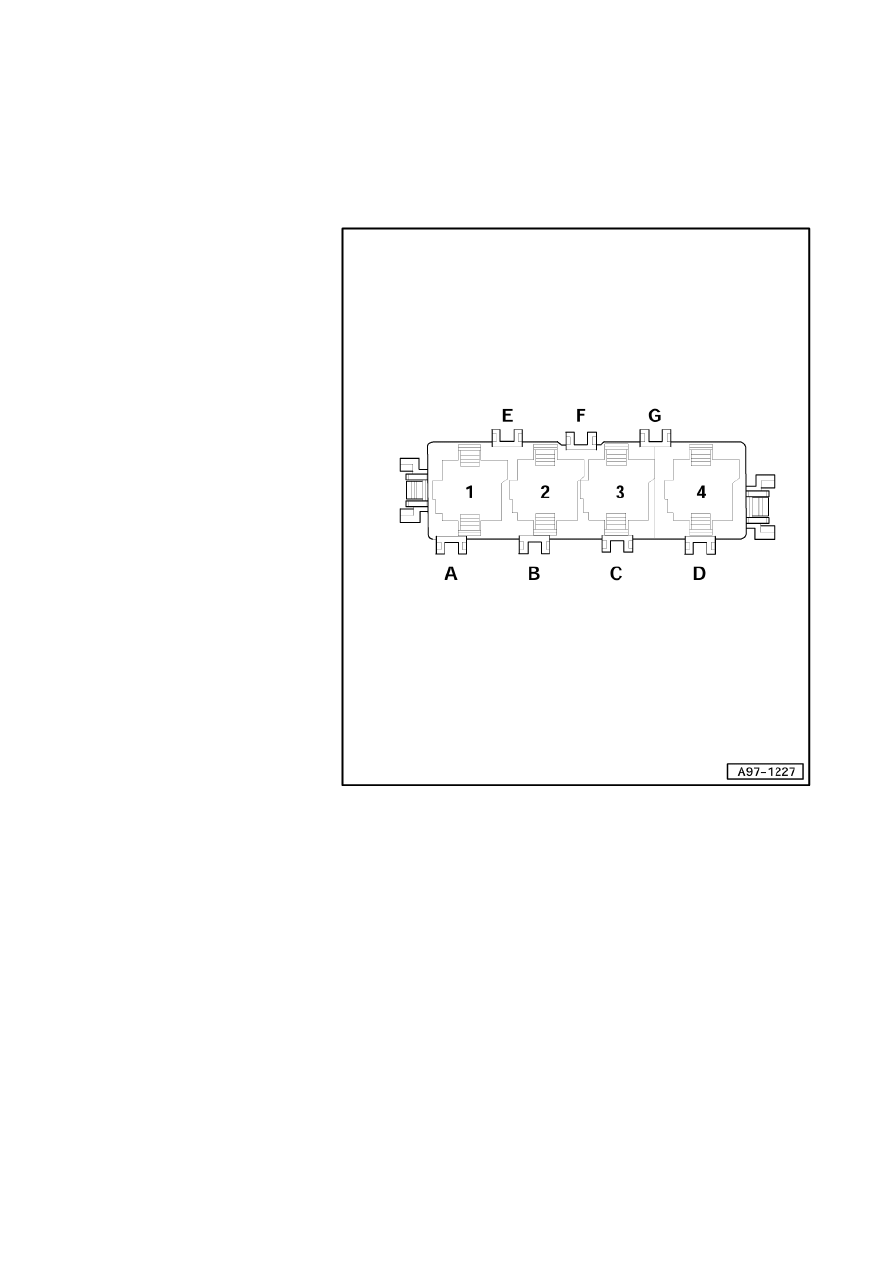
Audi A6
Fitting Locations
No. 802 / 62
Fuses in electronics box, right in plenum chamber
Position of fuses, fuse holder, from model year 2005
A - Vacant
B - Glow plug fuse -S125-
(80A), secondary air pump
fuse -S130- (50A)
C - Levelling system fuse -
S110- (40A)
D - Glow plug fuse 2 -S189-
(80A), radiator fan fuse for
3rd speed -S94- (15A)
(BGS)
E - Vacant
F - Vacant
G - Vacant
Strona 66 z 77
WI-XML
2011-05-20
file://C:\ElsaWin\docs\slp\A\en-GB\A005A6200802.htm

Audi A6
Fitting Locations
No. 802 / 63
Position of fuses, fuse holder, left-hand drive, from model year 2007
A - Vacant
B - Glow plug fuse -S125- (80
A), secondary air pump
fuse -S130- (50 A)
C - Levelling system fuse -
S110- (40 A)
C - Radiator fan fuse for 3rd
speed -S94- (30A) (5.0 l-
engine BUH)
D - Glow plug fuse 2 -S189-
(80 A)
E - Vacant
F - Vacant
G - Vacant
Strona 67 z 77
WI-XML
2011-05-20
file://C:\ElsaWin\docs\slp\A\en-GB\A005A6200802.htm
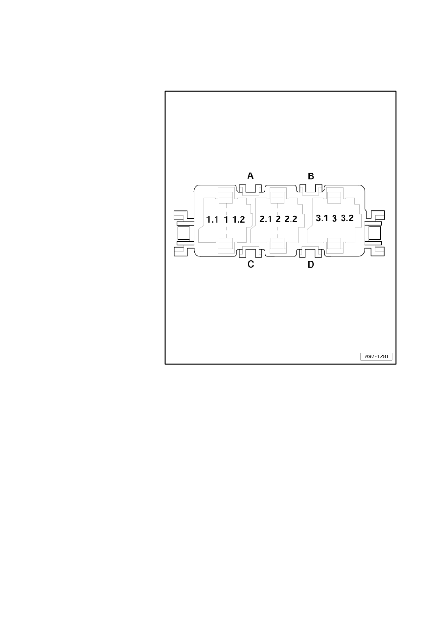
Audi A6
Fitting Locations
No. 802 / 64
Position of fuses, fuse holder, right-hand drive, from model year 2007
A - Vacant
B - Glow plug fuse -S125- (80
A), secondary air pump
fuse -S130- (50 A)
C - Levelling system fuse -
S110- (40 A), radiator fan
fuse for 3rd speed -S94-
(30 A)
D - Glow plug fuse 2 -S189-
(80 A)
Strona 68 z 77
WI-XML
2011-05-20
file://C:\ElsaWin\docs\slp\A\en-GB\A005A6200802.htm
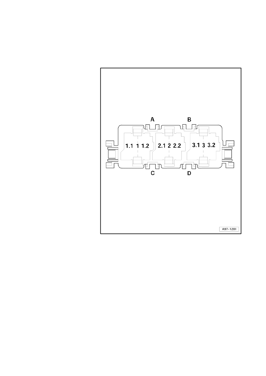
Audi A6
Fitting Locations
No. 802 / 65
Fuses in electronics box, left in plenum chamber
Position of fuses, fuse holder, left-hand drive, from model year 2007
A - Vacant
B - Vacant
C - Vacant
D - Vacant
Strona 69 z 77
WI-XML
2011-05-20
file://C:\ElsaWin\docs\slp\A\en-GB\A005A6200802.htm
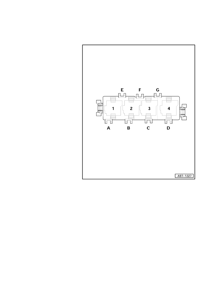
Audi A6
Fitting Locations
No. 802 / 66
Position of fuses, fuse holder, right-hand drive, from model year 2007
A - Vacant
B - Vacant
C - Vacant
D - Vacant
E - Vacant
F - Vacant
G - Vacant
Strona 70 z 77
WI-XML
2011-05-20
file://C:\ElsaWin\docs\slp\A\en-GB\A005A6200802.htm
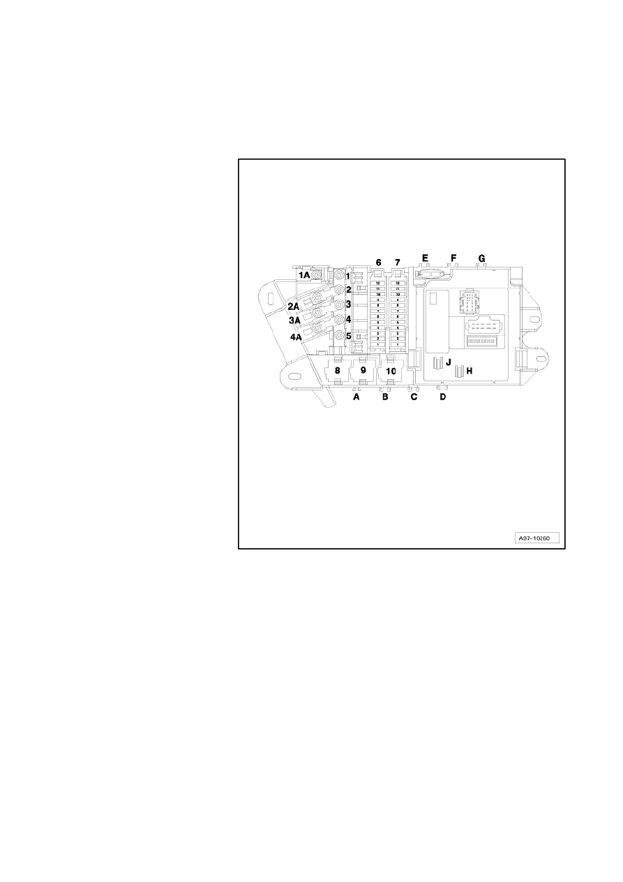
Audi A6
Fitting Locations
No. 802 / 67
Fuses, on right in luggage compartment
Position of fuses, fuse holder, from model year 2005
1 - Connection for wire to
fuse carrier ST1 and ST2
1A - Fuse -S131- vacant
2A - Fuse -S132- (Strip fuse
150A)
3A - Fuse -S133- (strip fuse
80A, only council
vehicles), fuse -S133-
(strip fuse 40A, only
driving school vehicles
and taxi)
4A - Fuse -S134- vacant
5 - Connection for wire from
battery +
6 - Fuse carrier ST1 (black)
7 - Fuse carrier ST2 (brown)
Strona 71 z 77
WI-XML
2011-05-20
file://C:\ElsaWin\docs\slp\A\en-GB\A005A6200802.htm
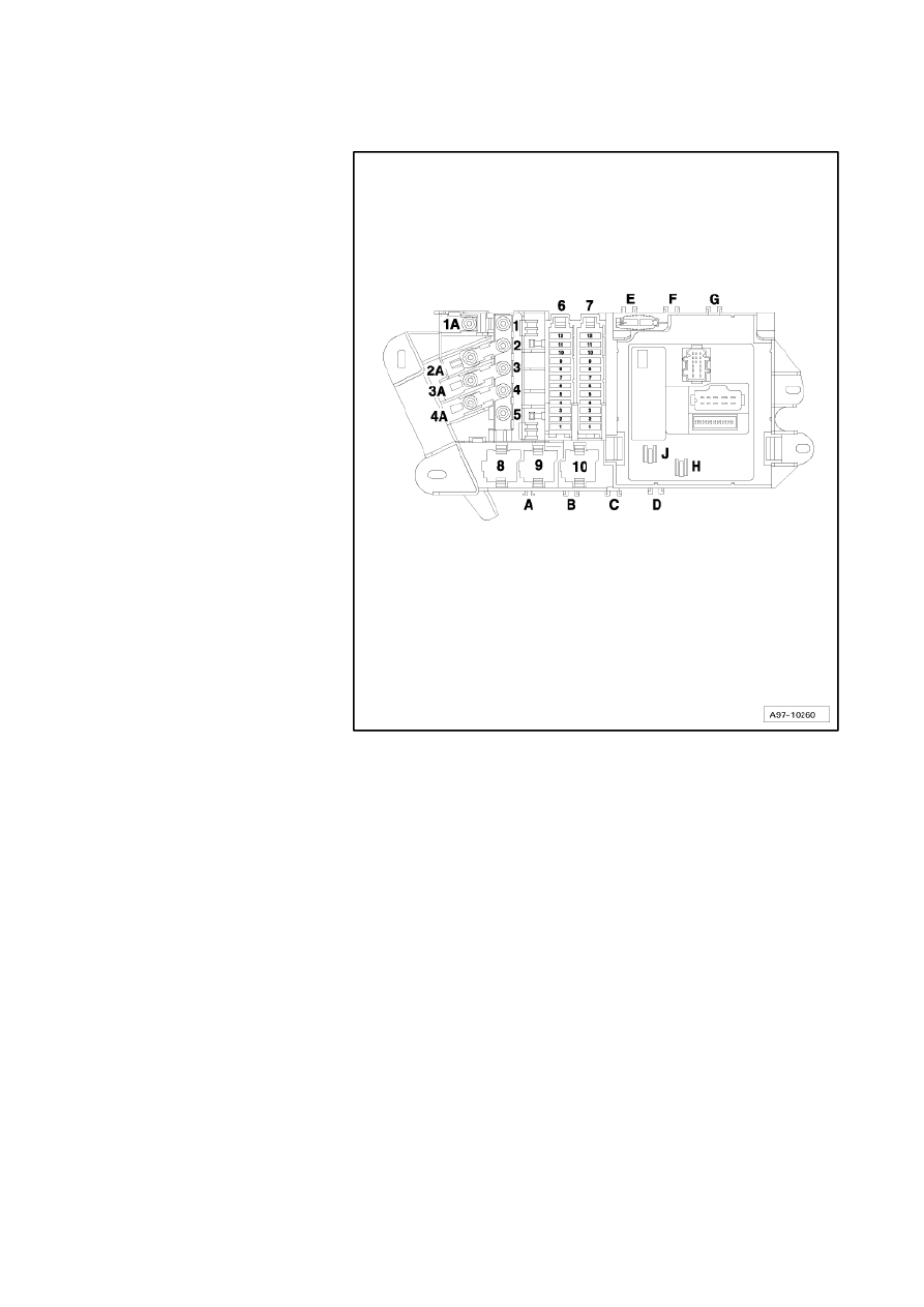
Audi A6
Fitting Locations
No. 802 / 68
B - Vacant
C - Heated rear window single
fuse - S41 (40A) (up to
October 2005)
D - Vacant
E - Vacant
F - Vacant
G - Vacant
H - Heated rear window single
fuse - S41 (40A) (from
November 2005)
J - Vacant
Strona 72 z 77
WI-XML
2011-05-20
file://C:\ElsaWin\docs\slp\A\en-GB\A005A6200802.htm
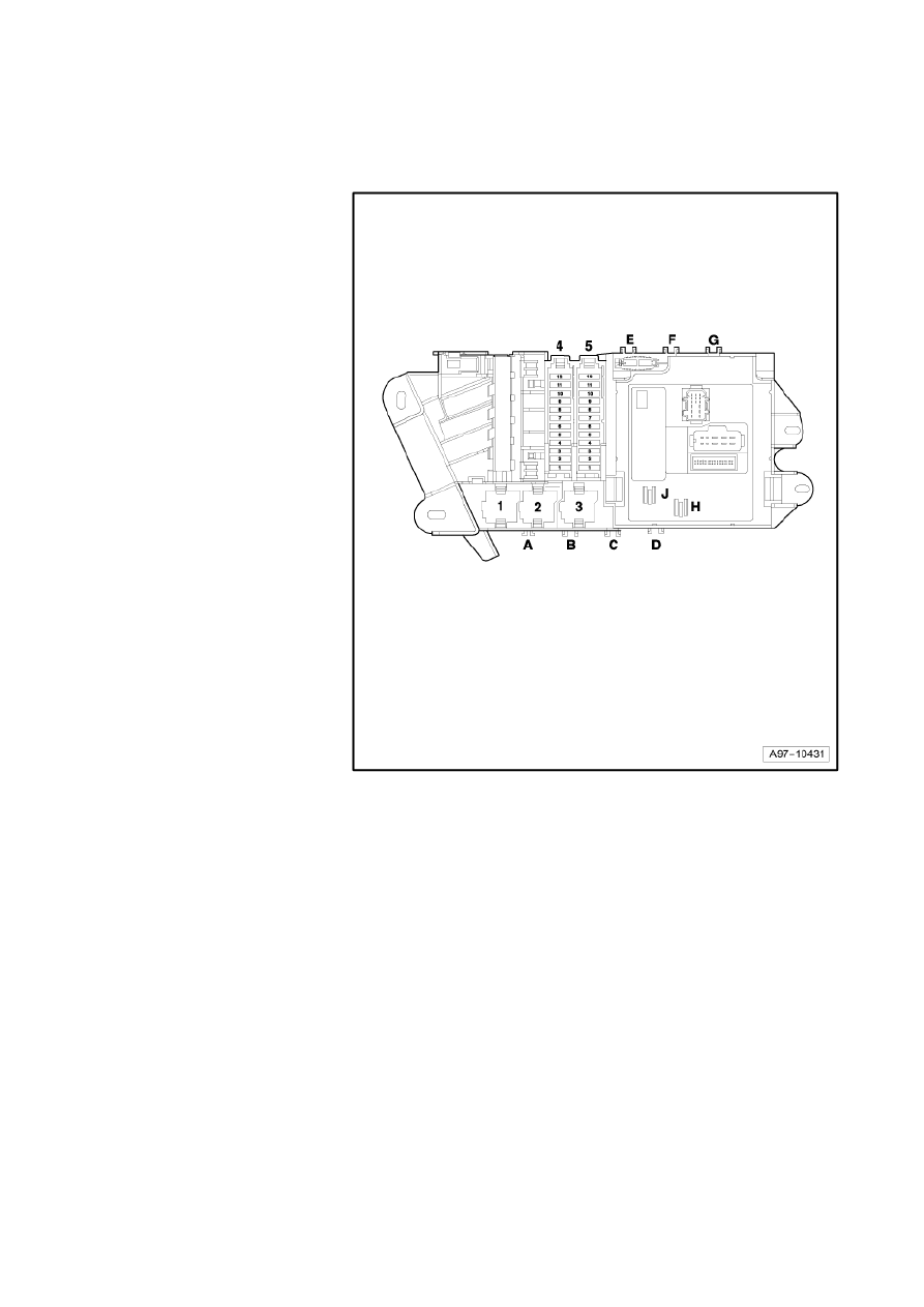
Audi A6
Fitting Locations
No. 802 / 69
Position of fuses, fuse holder, from model year 2007
4 - Fuse carrier ST1 (black)
5 - Fuse carrier ST2 (brown)
A - Vacant
B - Personal danger alarm
control unit -J476- (15 A)
right-hand drive only
C - Vacant
D - Signal system operating
unit control unit -J615- (25
A) right-hand drive only
E - Vacant
F - Vacant
G - Vacant
H - Heated rear window fuse -
S41- (40 A)
J - Vacant
Strona 73 z 77
WI-XML
2011-05-20
file://C:\ElsaWin\docs\slp\A\en-GB\A005A6200802.htm
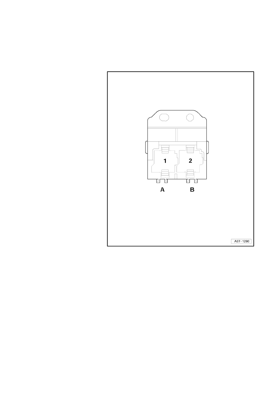
Audi A6
Fitting Locations
No. 802 / 70
Fuses on steering cross member
Position of fuses, fuse holder
A - Heater element fuse 1 -
S276- (1nd speed), (40A)
up to May 2007
for models from June 2007
→
page 802/61
B - Heater element fuse 2 -
S277- (2+3nd speed), (60A)
up to May 2007
for models from June 2007
→
page 802/61
Strona 74 z 77
WI-XML
2011-05-20
file://C:\ElsaWin\docs\slp\A\en-GB\A005A6200802.htm
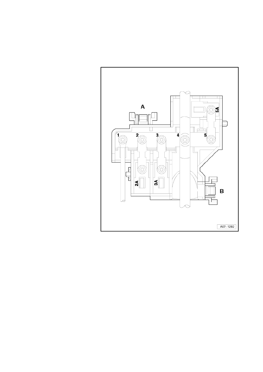
Audi A6
Fitting Locations
No. 802 / 71
Fuses on main fuse carrier electronics box, right in plenum chamber
Position of fuses, fuse holder
1 - Union (terminal 30)
2 - Radiator fan fuse for 2nd
speed -S104- (40A/ 60A)
3 - Radiator fan single fuse -
S42- (40A/ 60A)
4 - Battery positive cable
union
5 - Vacant
A - Vacant
B - Vacant
Strona 75 z 77
WI-XML
2011-05-20
file://C:\ElsaWin\docs\slp\A\en-GB\A005A6200802.htm
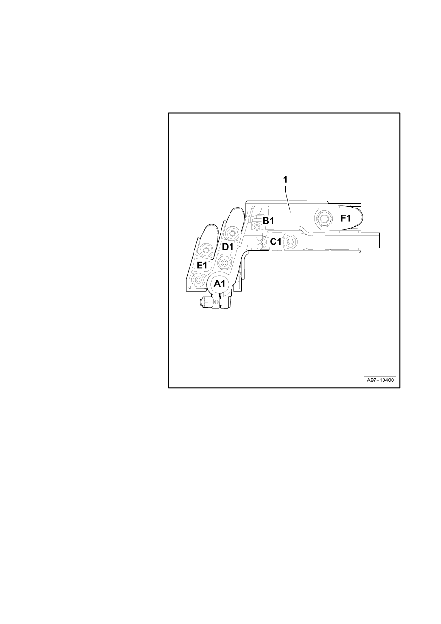
Audi A6
Fitting Locations
No. 802 / 72
Fuses in luggage compartment, rear right, on the battery
Position of fuses, fuse holder, from model year 2007
A1 - Connection battery
positive
B1 - Connection to energy
management control unit -
J644-
C1 - Strip fuse 40 A, only
driving school vehicles
and taxi
- Strip fuse 80 A, only
council vehicles
- Strip fuse 30 A, RS6
engine BUH only
D1 - Strip fuse 110 A, supply
fuse carrier right in
luggage compartment
E1 - Strip fuse 110 A, supply
onboard supply control
unit, ABS control unit -
J104-
F1 - Connection to starter -B-
Strona 76 z 77
WI-XML
2011-05-20
file://C:\ElsaWin\docs\slp\A\en-GB\A005A6200802.htm
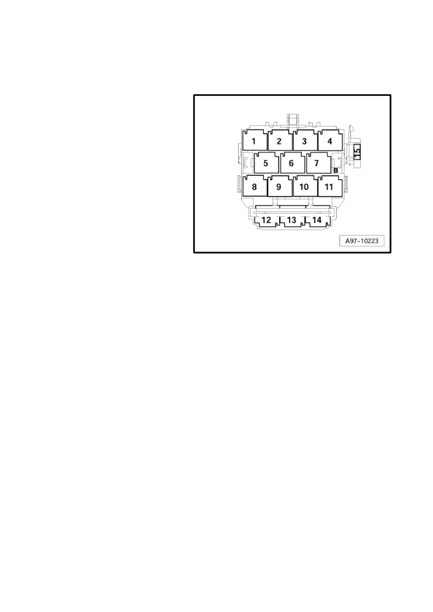
Audi A6
Fitting Locations
No. 802 / 73
Fuses on coupling station, lower part of right
A-pillar
Position of fuses, fuse holder
15 - Front passenger seat adjustment
thermal fuse 1 -S46- (30A) (is
dropped, from model year 2007)
15 - Front passenger seat adjustment fuse
1 -S46- (10A) (only lumbar support) (is
dropped, from model year 2007)
Strona 77 z 77
WI-XML
2011-05-20
file://C:\ElsaWin\docs\slp\A\en-GB\A005A6200802.htm
Wyszukiwarka
Podobne podstrony:
MINDY A6, A6F, A700F
a6 sch
2001 05 a6 c5 25tdi
A6 przekrój BB
Audi A6 Avant, od 2011
audi a6 a8 tdi czujnik srodka chlodzacego
JAK JEŹDZIĆ NA PRZEKŁADNI AUTOMATYCZNEJ, AuTO MoTO, Audi A6(1)
A6 Sprz enie zwrotne w uk?ach liniowych i nieliniowych
Informator A6 Matematyka rysunki, Pobrane
a6 KURS PROSTEGO FORMATOWANIA TEKSTU W OPISIE CHOMIKA
A6 gotowiec
Ośla łączka Wyprawa szusta A6 część 3
audi a6 przedostawanie sie wody do wnetrza pojazdu
A6 dla mailu
A6 AMINES
a6 05
a6 04
więcej podobnych podstron