Page 12
Desktop CNC Machine
Copyright © 2004 by B.C. King
Chapter 4:
Building the Components of the
Bearing Slides
Cutting the Aluminum
Extrusion
Tools Used
o
Well-aligned table saw with 80 or
100 tooth carbide tipped blade
o
Small mill file, or sanding sponge, or
fine grit sandpaper
o
Machinist’s scribe or awl
o
18” or longer ruler
o
Machinist’s square
o
Marking pen
Materials Used
o
48” of 1.75 x 4.5 storefront
aluminum extrusion material
o
Masking tape
The storefront aluminum extrusion material
can be cut easily on the table saw using an
80 or 100 tooth carbide tipped blade and the
miter guide. We chopped off an end first to
get a clean, square cut, then cut four pieces,
one each 3”, 11”,13”, and 15” long. We fed
the material slowly into the blade to keep it
from bending as we cut.
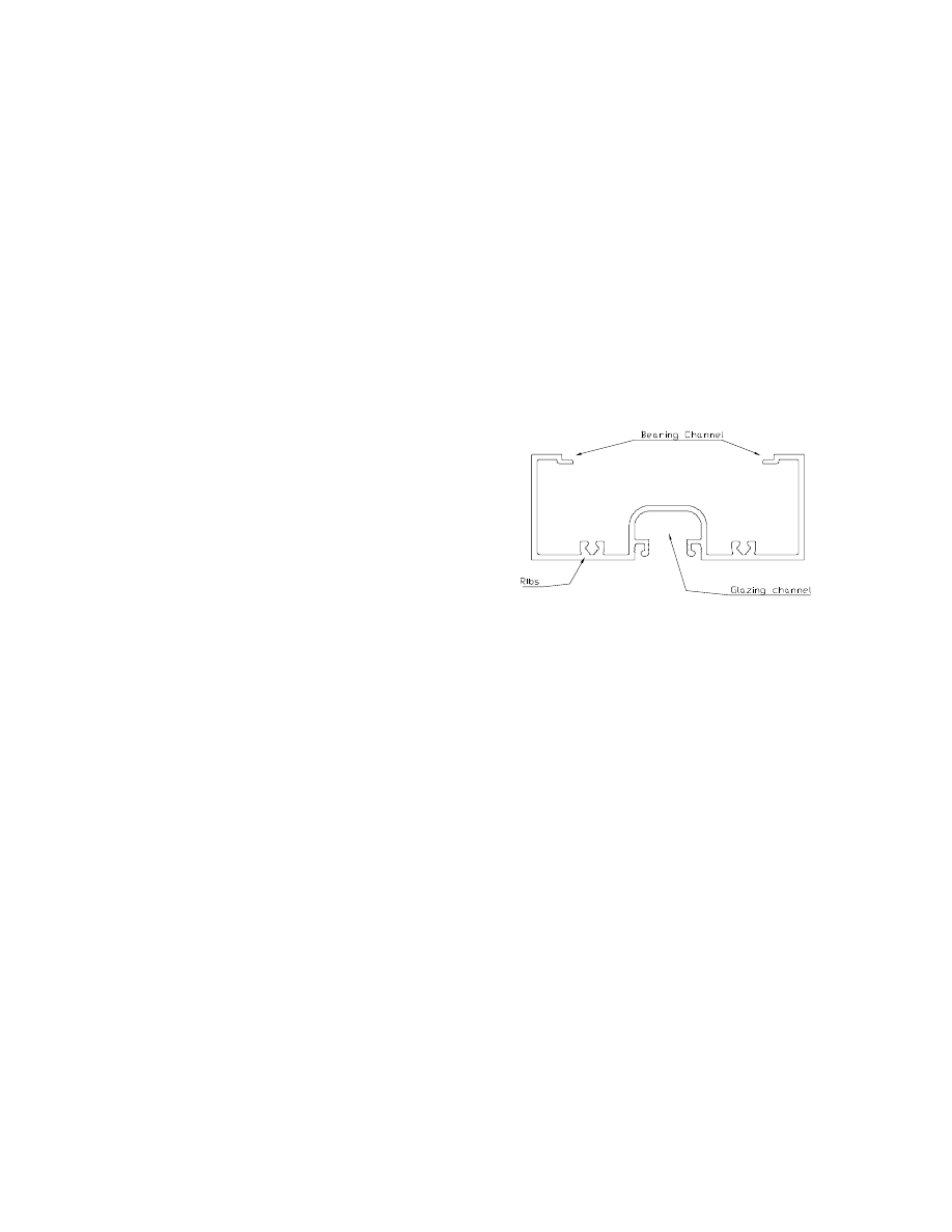
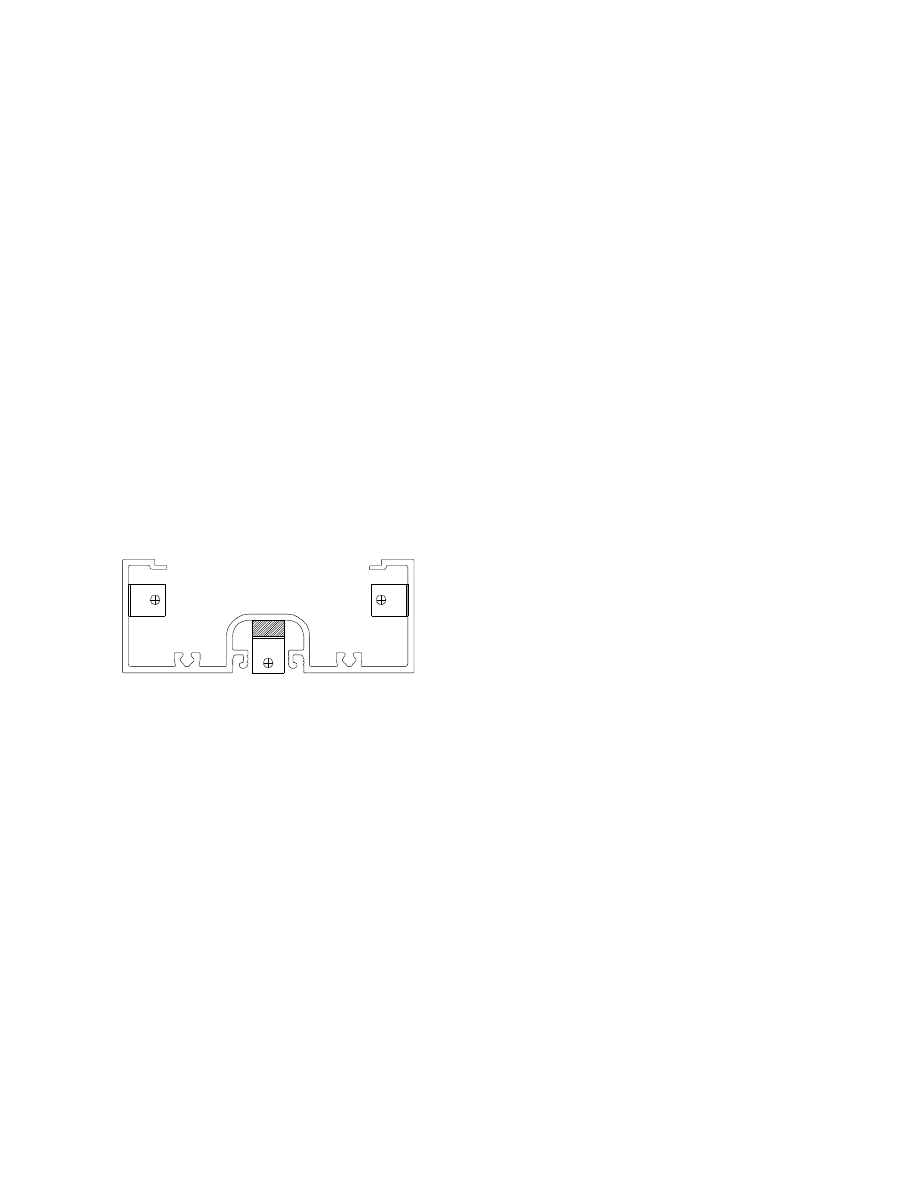
Figure 4 - End view of storefront aluminum
extrusion, with features labeled
The edges of all four pieces were filed
smooth, especially around the bearing
channel. We set aside the 3” piece. This
would be used in a later step to build the
power resistor heat sink.
The remaining pieces would be used to
construct the bearing slides. On the bottom
of each (the bottom is the face with the
glazing channel) we scribed a centerline
across the small dimension using a square
and a machinist’s scribe or an awl.
Desktop CNC Machine
13
Copyright © 2004 by B.C. King
On the bottom near one end we put a piece
of masking tape and label it “motor cap”
with marker. This was done to make it
easier to identify the sides of the extrusion.
By our convention, the sides of the extrusion
are identified with the extrusion positioned
top up and looking at it from the motor cap
end. It helped in construction to use
masking tape and a marker to label the left
and right sides of each extrusion at this
point.
We scribed the axis name into the bottom of
each piece near the center. This made it
easier to differentiate the pieces during
assembly. The 13” length was for the X axis
slide, the 15” length was for the Y axis slide,
and the 11” length was for the Z axis slide.
Drilling the Aluminum
Extrusions for Bracket and
Switch Holes
Tools Used
o
Templates #1 and #2: Bearing slide
extrusion side left/right end drilling
templates, from Appendix A
o
Center punch
o
Drill press with 1/8” and 3/16” twist
bits
o
Pencil
Materials Used
o
X, Y, and Z axis bearing slide
aluminum extrusions
o
Double sided tape
o
Scrap wood
o
Angle mounting bracket (Keystone
0.562” x 0.562” steel bracket with
threaded 6-32 holes, Mouser part #
534-4334 or equivalent)
The Bearing slide extrusion side drilling
templates were used to locate centers of all
holes in the sides of the bearing slide
extrusions. These holes are for the end cap
mounting bracket screws, the width
adjustment rods, and the limit switch
mounting screws. The left end template was
placed over the right side of a slide extrusion
so that it was aligned with the top, bottom,
and left end of the extrusion. Centers were
punched right through the template using a
machinist’s automatic center punch.
Using the right end template the process was
repeated to mark centers on the right end of
the right side of the extrusion. This process
was repeated again for both ends of the left
side of the extrusion, except the switch
mounting holes were not punched on this
side.
Refer to the pictures of the slides, which
indicate how these holes will be used when
assembled. All three slide extrusions were
punched in this manner.
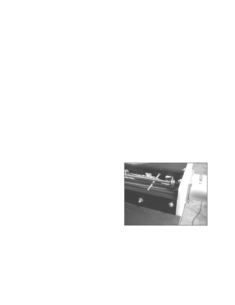
Photo 3- The left side of an assembled slide,
showing the position of the width adjusting rod
and the motor cap mounting screw
14
Desktop CNC Machine
Copyright © 2004 by B.C. King
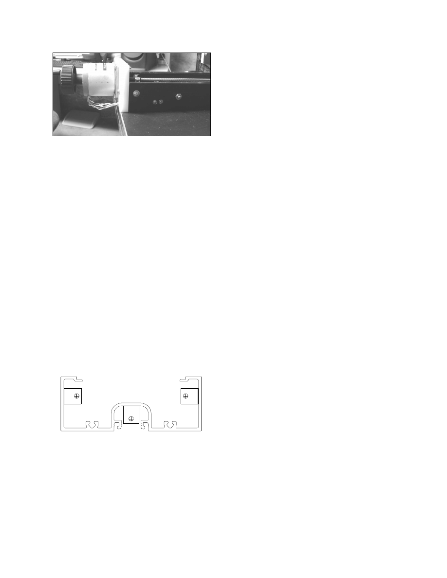
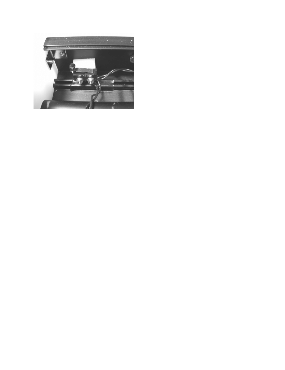
Photo 4 - The right side, showing position of the
motor cap mounting screw, limit switch screws,
and width adjusting rod
We marked the center of the glazing channel
on the bottom of each extrusion near the
ends, using a pencil. On the material we
used we found that the centerline had
already been marked when the material was
extruded. An angle mounting bracket was
positioned into place at the end of the
glazing channel (double sided sticky tape
helped to hold it in place temporarily) and
we marked the position of the hole with
pencil on the bottom (or top) of the glazing
channel. The figure shows where the
bracket would be placed. The process was
repeated for the mounting bracket hole at the
other end of the extrusion. We removed the
bracket and any tape and center punched
these marked holes.
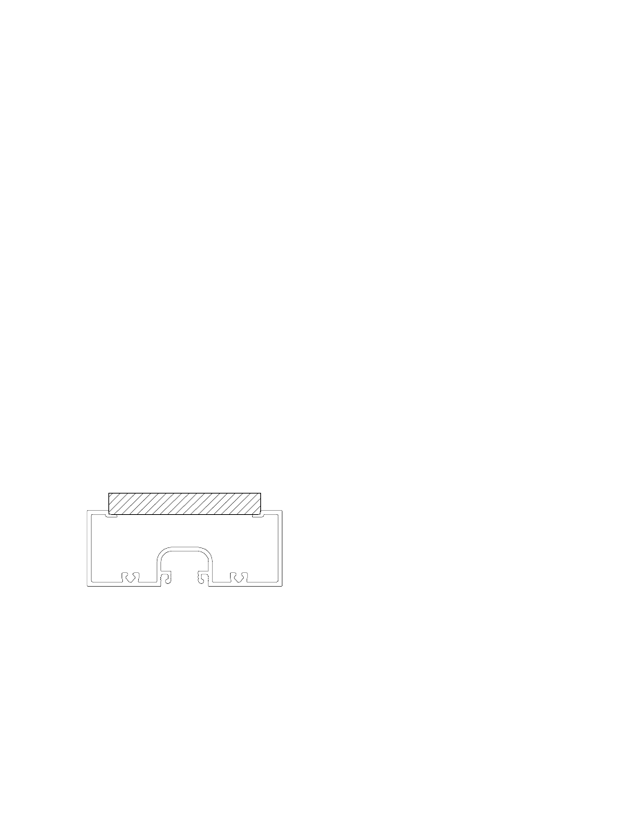
Figure 5 - The center cap mounting brackets are
positioned inside the glazing channel.
All mounting bracket holes in the sides of
the extrusion are 3/16”, as are the mounting
bracket holes in the glazing channel. The
holes for the width adjustment rods are also
3/16” in diameter. Mounting holes for limit
switches are 1/8”. Before drilling the holes
in the sides a wedge of scrap wood was
inserted inside the extrusion to keep the
sides from flexing when drilling.
We drilled all holes at marked centers, using
the drill press and appropriate bits.
Drilling the Aluminum
Extrusions for Mounting Holes
Tools Used
o
Template #3: Bearing slide extrusion
bottom drilling template, from
Appendix A
o
Center punch
o
Drill press with 1/4” and 3/8” twist
bits
Materials Used
o
X, Y, and Z axis bearing slide
aluminum extrusions
o
1 ¼” pipe flange
In the finished machine each bearing slide
will be mounted via four bolts or screws
through holes drilled in the bottom. As each
slide is mounted differently there are some
differences in the size and placement of the
holes.
We aligned the centerline of the bottom
template with the centerline scribed on the
bottom of the X axis slide extrusion. This
template aligns with the centerline, not with
one of the ends. Notice that there is a
smaller distance between the holes and the
centerline on the motor side of the channel.
The four holes were center punched right
through the template. This was repeated for
the Y axis slide extrusion.
Using the drill press with a ¼” bit, holes
were drilled at the marked centers. We

Desktop CNC Machine
15
Copyright © 2004 by B.C. King
made sure the extrusion was clamped down
well before drilling, and we drilled these
holes slowly. The holes may go through
ribs on the inside of the extrusion and these
will tend to divert the bit, causing the
extrusion to move.
The Z axis is a special case and had to be
marked differently. The bottom holes were
drilled to line up with holes on our 1 ¼”
pipe flange, but as close to the holes on the
template as possible. It is not possible to
show the centers for the pipe flange holes on
the template as not all pipe flanges have the
same dimensions. So we had to center our
flange over the drilling template and mark
the holes in the flange onto the template.
Then we positioned the template over the
bottom of the Z axis slide extrusion at the
marked centerline and center punched at the
centers of those holes. These holes were
drilled using the drill press and a 3/8” bit.
Since the holes did go through or near to
ribs on the inside of the extrusion that may
interfere with the mounting bolts and nuts
that will go through them, we had to cut and
install some spacers of UHMW that brought
the level of the floor of the extrusion up to
the level of the tops of the ribs. This
operation is described in a subsequent
section.
Drilling Axis-Specific Holes
Tools Used
o
Template #4: X axis side hole
drilling template, from Appendix A
o
Template #5: Y axis bottom hole
drilling template, from Appendix A
o
Template #6: Z axis bottom hole
drilling template, from Appendix A
o
Center punch
o
Drill press with 1/2” and 3/16” twist
bits
Materials Used
o
X, Y, and Z axis bearing slide
aluminum extrusions
Each axis slide gets some additional holes.
The Y axis extrusion gets a ½” hole in the
bottom near the end opposite to the one
marked “motor cap.” We positioned the Y
axis bottom hole drilling template on that
end of the bottom of the extrusion and center
punch through the template. We drilled a
½” hole at the punch. Then we filed (or
grinded, or sanded) the sharp edges of this
hole smooth, as the hole will be used to
route wires out of the channel.
The X axis extrusion gets an additional hole,
a ½” hole in the side of the extrusion near
the motor cap end. We positioned the X
axis side hole drilling template on the left
side (the side that does not have the limit
switch holes), on the motor cap end of the
extrusion. We center punched through the
template and drilled a ½” hole at the punch
mark. We wedged a scrap of wood inside
the extrusion before drilling to keep the
sides from flexing, just as we did when
drilling the mounting bracket and switch
holes.
The Z axis extrusion has holes drilled in the
back at the motor cap end. These holes are
used to mount the power resistor heat sink.
We positioned the Z axis bottom drilling
template on the bottom of the extrusion on
the motor cap end and center punched holes
through the template. 3/16” holes were
drilled at the punched marks.
16
Desktop CNC Machine
Copyright © 2004 by B.C. King
Cutting and Installing Optional
Extrusion Floor Spacers
Tools Used
o
Table saw
o
Ruler
o
Drill press with 1/4” Forstner bit
Materials Used
o
One of the bearing slide aluminum
extrusions
o
UHMW stock
When we drilled the mounting holes in the
bottoms of the extrusions we drilled through
or near to some ribs on the floor of the
extrusions. If the ribs on the floor of the
extrusions would interfere with mounting
hardware, then spacers that bring up the
floor to the level of the tops of the ribs
would need to be fashioned and installed.
We needed to do this. We checked to see if
this would be the case by temporarily
inserting a bolt through one of the mounting
holes from the bottom and putting a washer
and nut onto it. If the washer and nut won’t
fit flush to the floor of the extrusion or if
tightening them would cant the bolt over to
one side, then floor spacers will have to be
made. This was the case with our
extrusions. Note that extrusions made by
most manufacturers will have these ribs, so
the spacers will have to be made in most
cases.
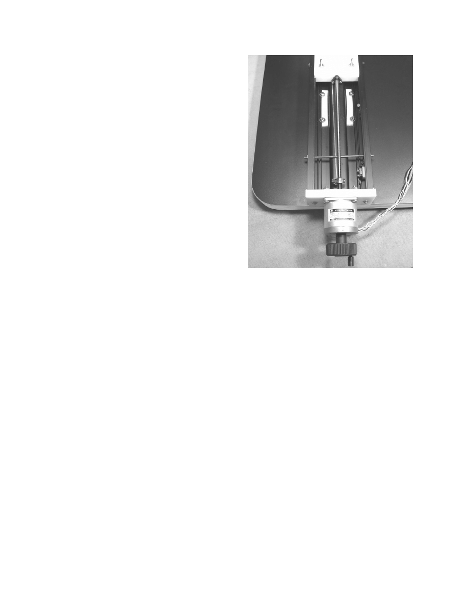
Photo 5 - UHMW spacers on the floor of the Y
axis slide, on the insides of the ribs
We measured the height of the tops of the
ribs from the floor of the extrusion and cut a
strip of UHMW material to that width and
approximately 24” long. From this we cut
six strips each 3 ½” long. These were to be
positioned onto the floors of the extrusions
over the places where the mounting holes
are drilled and butted up against the ribs
during assembly of the machine.
In some cases the spacers needed to be
positioned such that the mounting holes
went through them, so we needed to
temporarily hold each one in position, mark
them through the mounting holes from the
bottom of the extrusion, and then take them
out and drill them where marked. When the
holes were not right in the centers of the
spacers, they were drilled using a ¼”
Forstner bit.

Desktop CNC Machine
17
Copyright © 2004 by B.C. King
Cutting the End Caps
Tools Used
o
Table saw
o
Ruler
o
Scraper
Materials Used
o
One of the bearing slide aluminum
extrusions
o
UHMW stock
Each slide will have a cap on each end of the
extrusion. The caps are cut from ½”
UHMW stock. One of the caps serves as the
mount for the stepper motor while the other
cap serves as a bearing for the free end of
the lead screw. These caps are hereafter
referred to as the motor cap and the end cap
respectively.
The motor caps will be 2 ¾” high by 4 ½”
wide, and the end caps will be 2 1/8” high
by 4 ½” wide. All six caps can thus be cut
from a strip of UHMW stock 4 ½” wide.
We set up the table saw for a rip cut, and
placed one of the bearing slide extrusion
pieces between the fence and the blade as a
gauge for the width of the cut. The fence
was locked and the extrusion taken out, then
a strip of UHMW material approximately
24” long was ripped.
Next the table saw was set up for repetitive
2 1/8” wide cut offs, using the miter gauge.
We cut three 2 1/8” pieces from the UHMW
strip. These are the end caps. Then we set
up the saw for repetitive 2 ¾” wide cut offs,
and cut three pieces from the UHMW strip.
These are the motor caps.
We cleaned up all edges of the six caps by
putting a slight chamfer on them using the
scraper.
Drilling the Motor Caps and
End Caps
Tools Used
o
Template #7: End cap drilling
template, from Appendix A
o
Template #8: Motor cap drilling
template, from Appendix A
o
Center punch
o
Drill press with 1 ½” Forstner bit and
3/16”, ¼”, and 3/8” brad point bits
o
Hand held countersink
Materials Used
o
End caps
o
Motor caps
The motor cap template was taped to one of
the motor caps and we center punched
centers through the template. This was
repeated for the other two motor caps.
Using the 1 1/2” Forstner bit at low speed,
we drilled the large motor mount hole
through each motor cap.
Using the 3/8” brad point bit, we drilled the
wire access hole through each motor cap.
The four motor mount screw holes were
drilled through each motor cap, and the
bearing hole was drilled through each end
cap, using the ¼” brad point bit.
The three mounting holes in each motor cap
and each end cap were drilled, using the
3/16” brad point bit.
We cleaned up all hole edges with a hand
held countersink.
18
Desktop CNC Machine
Copyright © 2004 by B.C. King
Installing Width Adjustment
Rods
Tools Used
o
Small bolt cutter or hacksaw
o
Small mill file
o
Small machinist’s square
o
Small open end wrenches
Materials Used
o
All of the bearing slide aluminum
extrusions
o
(3 ft.) 8-32 threaded steel rod
o
(24) 8-32 nuts
The sides of the aluminum storefront
extrusion tend to cave in a little. This is not
an issue when this material is used for
glazing, but could cause problems in this
application. Width adjustment rods are used
to square up the extrusion and to stiffen its
walls.
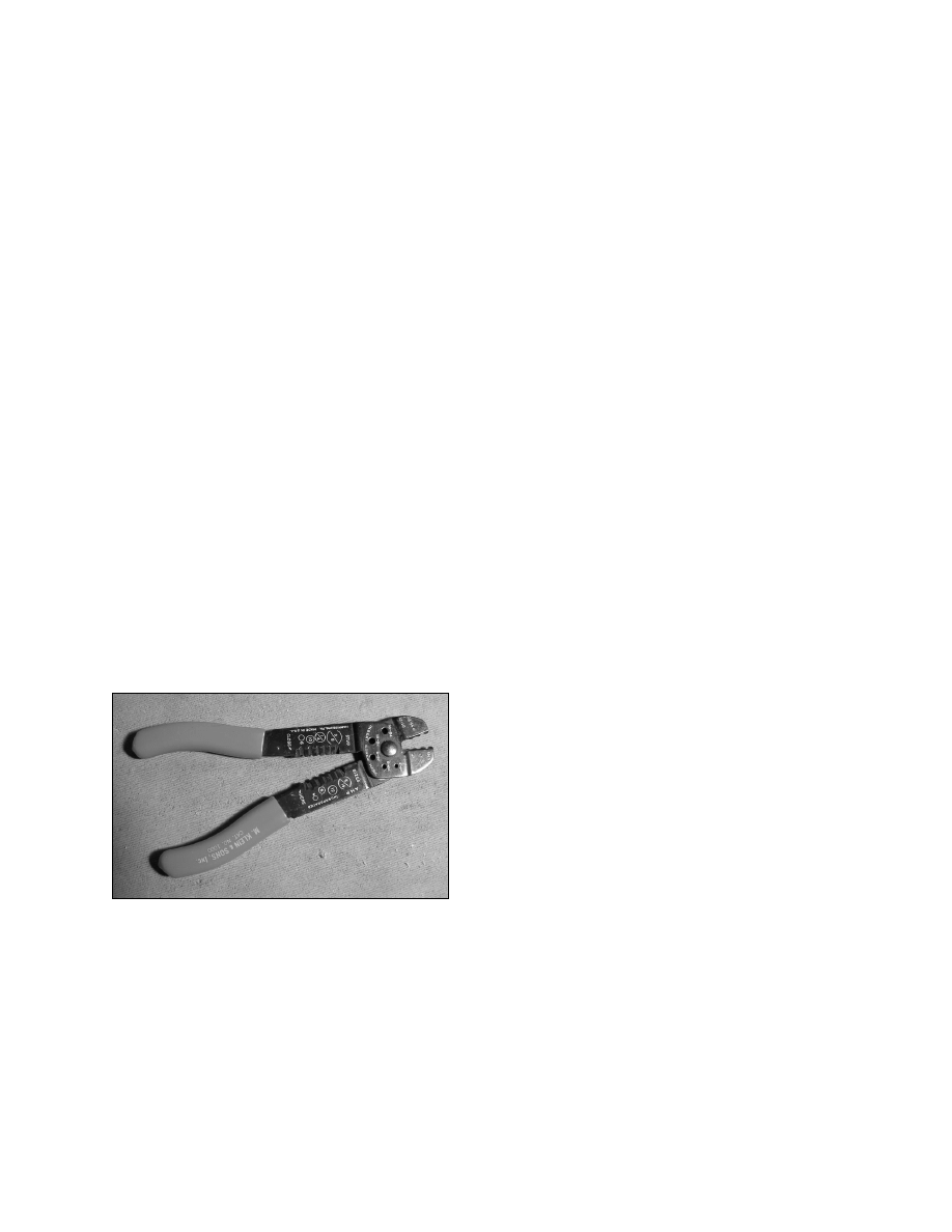
Photo 6 - Small bolt cutter with threaded holes
We cut six 5” long pieces of 8-32 threaded
rod. A bolt cutter with threaded holes like
the one shown was used, as these tend to not
bung up the threads while making the cut.
The rods were inserted through the
adjustment rod holes with nuts on both
insides and on both outsides. Each extrusion
in turn was placed on a flat surface like the
table saw table and using a small square or
one of the end caps we adjusted the nuts so
the ends of the extrusion were square. We
used a small ignition wrench to make the
adjustments. When done we tightened nuts
on opposite side of extrusion wall to keep
things from vibrating. We had to do this
adjustment again during assembly to ensure
a good fit with the bearing blocks.
These adjustment rods also provide some
means to compensate for bearing block side
wear.
Cutting Bearing Block Stock
Tools Used
o
Small ruler
o
Table saw
Materials Used
o
All of the bearing slide aluminum
extrusions
o
Scrap wood
o
UHMW material
o
Masking tape
The linear bearings of the slides are
composed of an upper bearing block which
slides in the bearing channel of the
extrusion, and a lower bearing block which
is mounted below the lips of the bearing
channel and is bolted to the upper block.
Movement of the bearing block assembly is
constrained to a single axis, along the length
of the extrusion. The shoulders of the lips in
the bearing channel keep the blocks from
moving from side to side. The floor of the
lips keep the blocks from moving down, and
the bottom bearing block, touching the
underside of the lips, keeps the assembly
from moving up. See figures 5 – 7 to see
how the blocks fit to the extrusion.
Desktop CNC Machine
19
Copyright © 2004 by B.C. King
We measured the width of the bearing
channel in a number of places on each axis
slide. The table saw fence was set for a rip
cut just a bit wider. A piece of scrap wood
was run through the saw to check the width
of cut and adjust the fence as necessary.
What we were looking for is a width just a
tiny bit wider than the channel. If the block
of wood will easily fit into the bearing
channel then it is too narrow. If it can’t be
squeezed in at all, it is too wide. If it can be
pushed in with a little effort then it is just
right.
When the width was dialed in, we cut a strip
of UHMW to that width and approximately
36” long. We checked for fit in the bearing
channel. It should have been a little too
wide and was. We then shimmed the edge
of the table saw fence with masking tape
(which is approximately 5 mils thick) and
cut again, then checked the width of the strip
again. This process was continued until we
got a good fit of the block stock in the
bearing channel with no play. The final
width of the channel will be adjusted with
the adjustment rods during assembly.
Figure 6 - The bearing block stock should fit in
the bearing channel with no play
Next we cut the bearing block stock into two
pieces 18” long, one for upper bearing
blocks and one for lower bearing blocks.
We labeled one of these pieces “upper
bearing block stock” and the other “lower
bearing block stock” to avoid confusion in
subsequent steps.
Routing Lower Bearing Block
Stock Edge Rabbets
Tools Used
o
Small ruler
o
Hand held router with edge guide, or
router in router table
o
Straight or rabbetting router bit
Materials Used
o
One of the bearing slide aluminum
extrusions
o
Scrap wood
o
1 piece of the UHMW bearing block
stock
o
Masking tape
Either a router table or a hand held router
with edge guide can be used for this
operation. We used the router table. We
made sure all parts of the router table were
square before beginning.
The first step was to route rabbets on the top
edges of the lower bearing block stock.
Dimensions for the depth and width of the
rabbets are determined by the dimensions of
the lip of the bearing channel of the
aluminum extrusion. The width of the
rabbets should be about 1/8” wider than the
width of the lip. This dimension is not
critical, as the side walls of the rabbets will
clear the inside edges of the lips once the
slide is assembled. The depth of the rabbets
should be a little less than the thickness of
the lips. When the slide is assembled, shims
will be placed between the upper and lower
bearing blocks to make up this difference.
The shims allow for adjustment for wear on
the upper and lower bearing surfaces.
This cut can be made with any flat bottom
router bit, but we have a bottom cleaning bit

20
Desktop CNC Machine
Copyright © 2004 by B.C. King
with a really flat bottom and using it made
measurement easier. We inserted the bit in
the router and adjusted the depth of cut to
zero. It is important to do this with the
router positioned as it will be used (i.e.,
upside down in our router table) as the
router shaft usually has a little end play in it.
Next we adjusted the fence of the router
table for the desired width of cut. Again,
this dimension is not critical as long as the
rabbet will be wider than the lip of the
bearing channel of the extrusion. The depth
of cut was adjusted to be about half of the
thickness of the lip of the bearing channel.
We made a test cut on a piece of scrap. We
then placed the upper bearing block stock in
the bearing channel of one of the pieces of
aluminum extrusion, and positioned the
piece of scrap under it to check the depth of
the rabbet. If it was too deep, we’d adjust
the depth of cut again and try again with a
piece of scrap. If it was too shallow, we’d
adjust the router for a slightly deeper cut and
make another pass at the piece of scrap.
Again, the idea was to get it so the depth of
the rabbet was a little less than the thickness
of the bearing channel lip, such that some
thin shims could be used to make up the
difference. Ideally the gap should be
between 10 and 20 mil. Masking tape is
about 5 mils thick, so this means that we
should be able to shim the gap between the
upper block stock and the test piece with 2
to 4 thicknesses of masking tape. If we
found we needed more than four
thicknesses, we cut the rabbet a little deeper
and tried again.
Figure 7 - Lower bearing block stock with rabbits
on top edges. Depth of rabbits should be 10 - 20
mils less than thickness of bearing channel lips.
When we got the depth of cut dialed in right,
we rabbetted the two top edges of the
bearing block stock. A final check of the
dimensions was made using the upper
bearing block stock, one of the pieces of the
aluminum extrusion, the lower bearing block
stock, and masking tape for shims.
Routing Upper Bearing Block
Stock Center Channel
Tools Used
o
Router in router table
o
5/8” round nose router bit
Materials Used
o
The upper bearing block stock
A rounded channel is routed through both
upper and lower bearing block stock pieces
to make room in the bearing blocks for the
anti-backlash nuts. We inserted a 5/8”
round nose bit in the router. The depth of
cut was set to 3/32”. We set the router table
fence to make the cut right down the center
of the upper bearing block stock. Note that
the upper bearing block stock is the piece
that does not have the rabbits in it. This
channel was cut. The side with the channel
Desktop CNC Machine
21
Copyright © 2004 by B.C. King
in it will be the bottom of the upper bearing
blocks.
Routing Lower Bearing Block
Stock Center Channel
Tools Used
o
Router in router table
o
5/8” round nose router bit
Materials Used
o
The lower bearing block stock
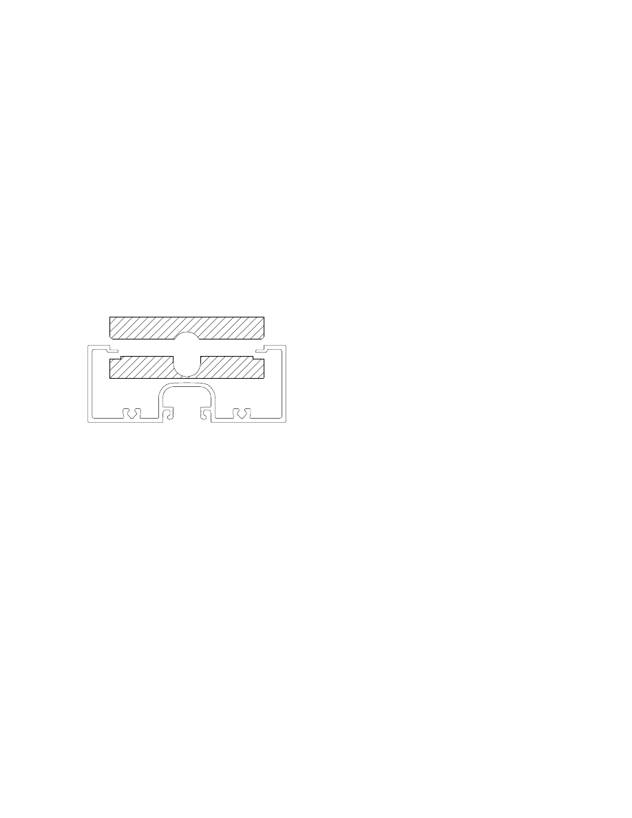
Figure 8 - A channel was routed in both the upper
and lower bearing block stock to provide room for
the lead screw and anti-backlash nut
With the router still set up as above, we
routed a channel in the top face of the lower
bearing block stock. This is the same face
that has the rabbets cut into it. We increased
the depth of cut by approximately ¼” and
cut the channel a little deeper. Then the
depth of cut was set for the final pass to
7/16” and the channel was cut again. When
handling the lower bearing block stock in
subsequent steps we took care not to fold the
stock on the thin edge remaining after the
channel was cut.
Cutting bearing Blocks
Tools Used
o
Table saw with miter guide
Materials Used
o
The upper bearing block stock
o
The lower bearing block stock
Using the miter guide on the table saw we
cut 3 blocks, each 4 ½” long from both the
upper and lower bearing block stock pieces
(i.e., 3 upper blocks and 3 lower blocks).
When cutting the lower bearing blocks to
length the stock was positioned with the
channel side down.
Cutting the Table
Tools Used
o
Small ruler
o
Table saw
Materials Used
o
UHMW material
The table was cut from a piece of UHMW
using the table saw. Its dimensions are 6” x
8”.
Drilling Bearing Blocks and
Table
Tools Used
o
Drill press with 5/8” Forstner bit,
13/64” twist bit, and ¼” twist bit
o
Template #9: Bearing block drilling
template, from Appendix A
22
Desktop CNC Machine
Copyright © 2004 by B.C. King
o
Template #10: Table drilling
template, from Appendix A
o
Scissors
o
Center punch
Materials Used
o
Upper bearing blocks
o
Lower bearing blocks
o
Table
Since the width of the bearing channel is
different in extrusions made by different
manufacturers, the width of the bearing
blocks made to fit those channels will be
different as well. For this reason the bearing
block drilling template has variable block
width. In the next operation we figured out
the width of our blocks and cut the template
accordingly.
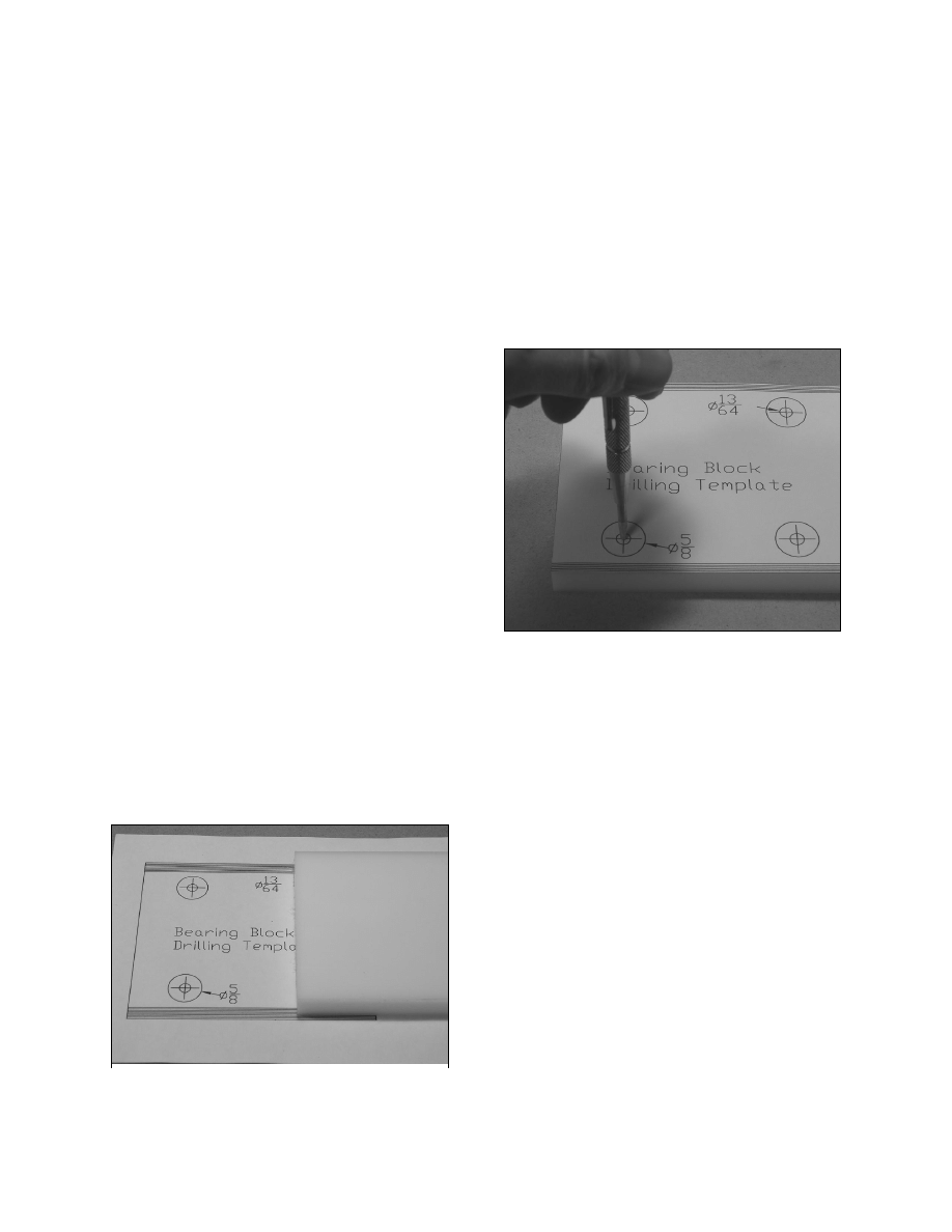
One of the bearing blocks was placed over
the bearing block drilling template drawing
so the ends of the block lined up with the
ends of the template. The template drawing
has a number of lines on each side, so that it
can be used with bearing blocks of different
widths. We centered the block on the
template and marked which of the side lines
represented the sides of the block. The
block was removed and checked to be sure
the block was centered.
Once we had it centered we cut out the
drilling template using the end lines and the
side lines we marked. The template was
now sized to our bearing blocks. We center
punched holes on the top faces of the upper
bearing blocks and on the bottom faces of
the lower bearing blocks using the bearing
block drilling template. We also center
punched holes in the table using the table
drilling template.
Photo 8 - Center punching the bearing blocks
right through the template
A 5/8” Forstner bit was chucked in the drill
press and the depth stop set to drill ¼” deep
counterbore holes in the lower bearing
blocks. We drilled these at the center
punches in the bottom faces of the lower
bearing blocks.
The depth stop was set 1/16” lower, to drill
5/16” deep counterbores. These were drilled
in the top faces of the upper bearing blocks
and in the table at the center punch marks.
A 13/64” bit was chucked in the drill press
and we drilled through all the counterbore
holes in the upper and lower bearing blocks.
We used a ¼” bit to drill through the
counterbore holes in the table.
Photo 7 - Measuring the width of the bearing
block template
Desktop CNC Machine
23
Copyright © 2004 by B.C. King
Cutting and Drilling Motor
Cap Bracket Spacers
Tools Used
o
Small ruler
o
Table saw
o
Drill press with 3/16” twist bit
Materials Used
o
UHMW material
The motor cap mounts to the extrusion with
three screws and brackets. One of these is
located on the underside of the glass channel
of the extrusion. That bracket is mounted on
a spacer.
Figure 9 - The center motor cap mounting bracket
is mounted on a spacer on the underside of the
glass channel
We cut a ¼” wide strip of UHMW stock on
the table saw. This piece was approximately
6” long. The strip was placed on its side and
three 3/16” holes were drilled through it,
approximately 1” apart. Using the table
saw, the strip was cut into three spacers,
each 1” long with a hole in the center.
These spacers were used to mount the center
mounting bracket for the motor cap.
Cutting and Drilling Limit
Switch Spacers
Tools Used
o
Small ruler
o
Table saw
o
Drill press with 3/32” twist bit
o
Awl
Materials Used
o
UHMW material
Each slide has a limit switch at each end,
mounted so the lower bearing block trips the
switch as it nears the end of the extrusion.
These switches are used in the machine to
prevent attempted travel of the bearing
blocks beyond the ends of the slide. The
switches are mounted to the inside walls of
the extrusion on spacers. The spacers
position the switches so the lower bearing
block can contact them.
We cut a 3/8” wide strip of UHMW stock on
the table saw. The piece was approximately
12” long. The strip was positioned on the
bench so one of the 3/8” faces was on top
and we put one of the limit switches on top
of it so that the end of the switch lined up
with one end of the strip. Using a sharp awl,
a line was scribed on the strip next to the
other side of the switch. Before moving the
switch we used the awl to center punch two
holes in the strip, through the switch’s
mounting holes. Next we slid the switch
down the strip until its other edge was lined
up with the scribed mark. We repeated this
process until we had scribed cut lines and
center punches for six spacers.
24
Desktop CNC Machine
Copyright © 2004 by B.C. King
Photo 7 - The limit switches are mounted on
spacers on the inside walls of the extrusion
We drilled the mounting holes through the
strip at the center punches using a 3/32” bit.
Using the table saw, we cut the strip into six
spacers on the scribed lines.
Wyszukiwarka
Podobne podstrony:
24 CNC machine feedback devices
Canadian Patent 24,033 Improvements in Dynamo Electric Machines
24 piątek
24(45)RUP
ostre białaczki 24 11 2008 (kurs)
ZPSBN T 24 ON poprawiony
24 NIEDZIELA ZWYKŁA A
Wykład 24
4 wykład0 24 10 2007
Atrybucje 23 24
od 24 do 32
24 G23 H19 QUALITY ASSURANCE OF BLOOD COMPONENTS popr
4 JM02 JS05 24 29 złamania
24 gold & 20's
mspo 24 2
24 Wykonywanie prac z zakresu obróbki ręcznej
więcej podobnych podstron