2004 Microchip Technology Inc.
DS00937A-page 1
AN937
INTRODUCTION
Continuous processes have been controlled by
feedback loops since the late 1700’s. In 1788, James
Watt used a flyball governor on his steam engine to
regulate its speed. The Taylor Instrument Company
implemented the first fully functional Proportional,
Integral and Derivative (PID) controller in 1940.
Although feedback control has come a long way since
James Watt, the basic approach and system elements
have not changed. There are several elements within a
feedback system; for discussion purposes, we will use
a home heating temperature control system as our
model in the descriptions below.
• Plant – The physical heating and cooling parts of
the system.
• Sensors – The devices (thermistors measuring
temperature) that measure the variables within
the Plant.
• Setpoint – This is a value (i.e., 70 degrees),
which is converted to a voltage that the process
drives towards.
• Error Signal – This is the difference between the
response of the Plant and the desired response
(Setpoint). In a house, the thermostat may be set
to 70 degrees, but the temperature is actually
65 degrees, therefore resulting in an error of
5 degrees (Error = Setpoint – Measured).
• Disturbances – These are unwanted inputs to
the Plant, which can be common. A disturbance
would be an open entry door allowing a gust
of cold air to blow in, quickly dropping the
temperature and causing the heat to come on.
• Controller – Intentionally left for last, this is the
most significant element of a control system. The
Controller is responsible for several tasks and is
the link that connects together all of the physical
and nonphysical elements. It measures the output
signal of the Plant’s Sensors, processes the
signal and then derives an error based on the
signal measurement and the Setpoint. Once the
sensor data has been collected and processed,
the result must be used to find PID values, which
then must be sent out to the Plant for error
correction. The rate at which all of this happens is
dependent upon the Controller’s processing
power. This may or may not be an issue
depending on the response characteristic of the
Plant. A temperature control system is much more
forgiving on a Controller’s processing capabilities
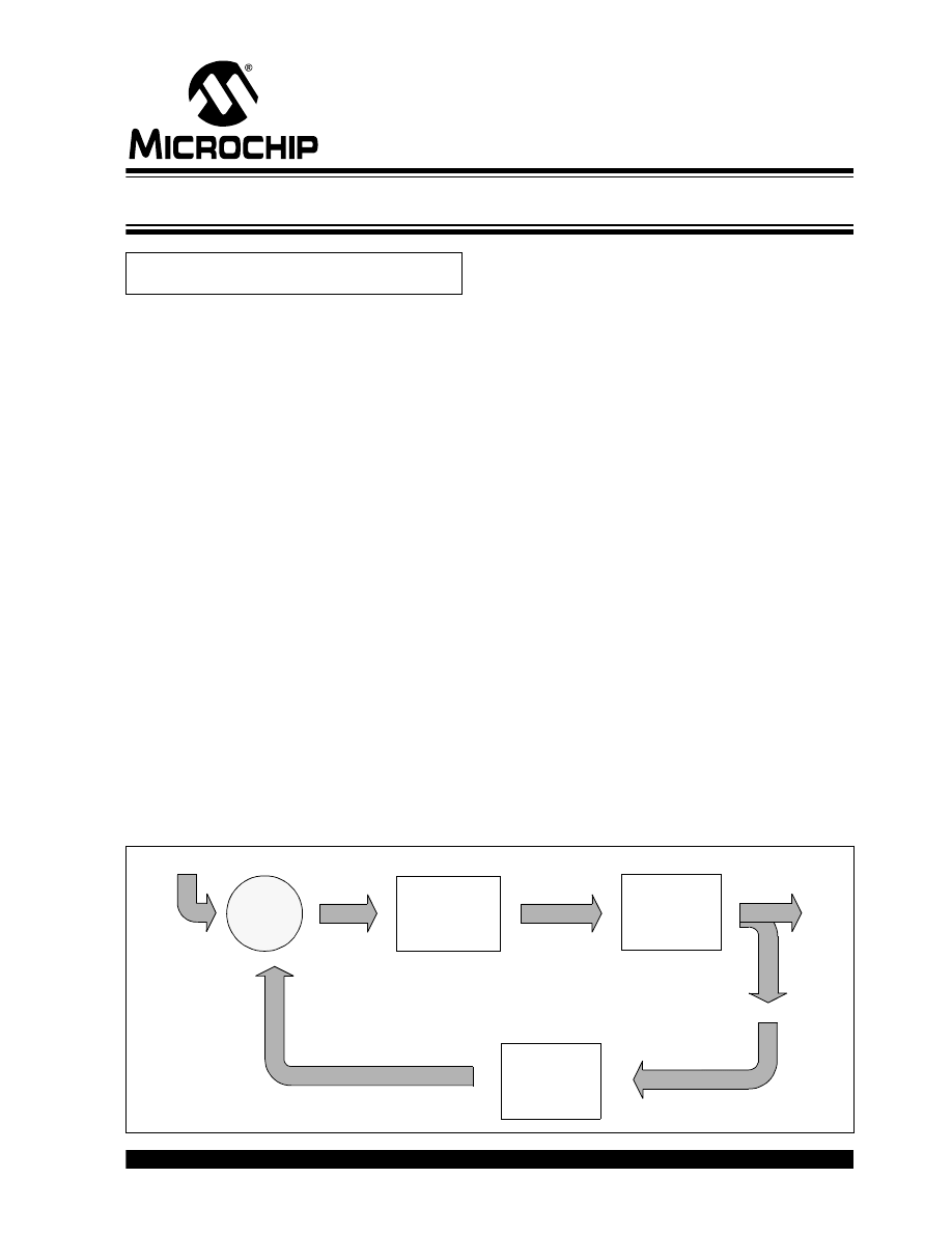
than a motor control system. Figure 1 shows a
basic block diagram of a feedback control system.
FIGURE 1:
FEEDBACK CONTROL LOOP
Author:
Chris Valenti
Microchip Technology Inc.
Controller
Plant
Feedback
Setpoint
Error
Controller
Output
Process
Variable
–
+
Implementing a PID Controller Using a PIC18 MCU
AN937
DS00937A-page 2
2004 Microchip Technology Inc.
OBJECTIVES
The objectives for this application note are to:
• discuss in detail the three elements of a PID
Controller: Proportional, Integral and Derivative
• discuss a firmware PID routine on a PIC18 device
• discuss the implementation of a firmware-based
PID that has the flexibility of adapting to different
systems, but is capable of being specifically tuned
later on
• discuss the details of tuning a PID once
implementation has been completed
SOURCE CODE OVERVIEW
Before going further, let’s discuss how the PID source
code is configured. There is no specific way a PID
should be implemented in firmware; the methods
discussed in this application note only touch upon a few
of the many possibilities.
The PID routine is configured in a manner that makes
it modular. It is intended to be plugged into an
existing piece of firmware, where the PID routine is
passed the 8-bit or 16-bit error value (Desired Plant
Response – Measured Plant Response). Therefore,
the actual error value is calculated outside of the PID
routine. If necessary, the code could be easily modified
to do this calculation within the PID routine. The PID
can be configured to receive the error in one of two
ways, either as a percentage with a range of 0 to 100%
(8-bit), or a range of 0 to 4000 (16-bit). This option is
configured by a
#define
statement at the top of the
PID source code with the PID’s variable declarations.
The gains for proportional, integral and derivative all
have a range of 0 to 15. For resolution purposes, the
gains are scaled by a factor of 16 with an 8-bit
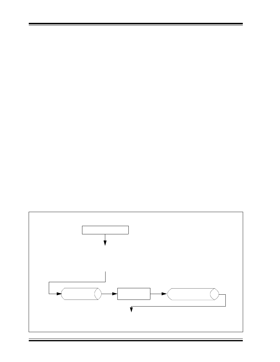
maximum of 255. A general flow showing how the PID
routine would be implemented in the main application
code is presented in Figure 2.
There were two methods considered for handling the
signed numbers. The first method was to use signed
math routines to handle all of the PID calculations. The
second was to use unsigned math routines and
maintain a sign bit in a status register. The latter
method was implemented. There are five variables that
require a sign bit to be maintained:
•
error
•
a_error
•
p_error
•
d_error
•
pid_error
All of these sign bits are maintained in the pid_stat1
register (see Register 1).
Although all of the PID status bits are shown in
Register 1 and Register 2, the user needs only to be
concerned with the error sign bit (err_sign) and the PID
final result sign bit (pid_sign). The err_sign bit is
inserted into the PID routine along with the error. The
user will check the pid_sign bit to determine which
direction the Plant must be driven.
FIGURE 2:
PID FIRMWARE IMPLEMENTATION
Start
Application Initialization
Call
PIDInitialize
ISR (with PID Code)
Application Main
Code...
Code... (Calculates Error)
error0:error1
Call
PIDMain
pid_out0:pid_out2
Code... (Applies PID Result to Plant)
Code...
End

2004 Microchip Technology Inc.
DS00937A-page 3
AN937
Firmware Variables and Constants
The list of firmware variables and constants and their
definitions that are discussed in this application note
are shown in Table 1.
TABLE 1:
FIRMWARE VARIABLES AND CONSTANTS
Variable/Constant
Type
Definition
error0:error1
Error Variable
16-bit variable, difference between the Setpoint and measured output of
the Plant
a_error0:a_error1
Error Variable
16-bit variable, accumulative error which is the sum of all past errors
d_error0:d_error1
Error Variable
16-bit variable, difference between
error0:error1
and
p_error0:p_error1
p_error0:p_error1
Error Variable
16-bit variable, value of the last error
a_err_1_lim
Error Variable
8-bit constant defining the accumulative error limits
a_err_2_lim
Error Variable
8-bit constant defining the accumulative error limits
kd
Gains
8-bit variable, derivative gain, max. = 15 (16 levels)
ki
Gains
8-bit variable, integral gain, max. = 15 (16 levels)
kp
Gains
8-bit variable, proportional gain, max. = 15 (16 levels)
pid_stat1
Status Register
8-bit variable, status bit register (see Register 1)
pid_stat2
Status Register
8-bit variable, status bit register (see Register 2)
deriv0:deriv2
Terms
24-bit variable, value of the derivative term
integ0:integ2
Terms
24-bit variable, value of the integral term
pid_out0:pid_out2
Terms
24-bit variable, final PID results
prop0:prop2
Terms
24-bit variable, value of the proportional term
timer1_hi
Time Base
8-bit constant loaded into the TMR1H register
timer1_lo
Time Base
8-bit constant loaded into the TMR1L register
Note:
In 16-bit variables, the first variable is the Most Significant Byte (MSB), whereas the second variable is the
Least Significant Byte (LSB). For example, in the variable
error0:error1
,
error0
= MSB 8-bit and
error1
= LSB 8-bit.
In 24-bit variables, the first variable is the MSB, whereas the last variable is the LSB. For example, in the
variable
pid_out0:pid_out2
,
pid_out0
= MSB 8-bit and
pid_out2
= LSB 8-bit.

AN937
DS00937A-page 4
2004 Microchip Technology Inc.
Data Registers
The pid_stat1 and pid_stat2 Data registers contain the
individual PID status bits. The following two registers
provide brief bit descriptions and their associated
values.
REGISTER 1:
pid_stat1 DATA REGISTER
REGISTER 2:
pid_stat2 DATA REGISTER
pid_sign
d_err_sign
mag
p_err_sign
a_err_sign
err_sign
a_err_zero
err_zero
bit 7
bit 0
bit 7
pid_sign: Indicates sign of final PID result
1
= Result was positive
0
= Result was negative
bit 6
d_err_sign: Indicates sign of the derivative term
1
= Result was positive
0
= Result was negative
bit 5
mag: Indicates which variable is greater in magnitude (AARGB or BARGB)
1
= Result was AARGB
0
= Result was BARGB
bit 4
p_err_sign: Indicates sign of the previous error
1
= Result was positive
0
= Result was negative
bit 3
a_err_sign: Indicates sign of the accumulative error
1
= Result was positive
0
= Result was negative
bit 2
err_sign: Indicates sign of the error (input into the PID)
1
= Result was positive
0
= Result was negative
bit 1
a_err_zero: Indicates if the accumulative error is equal to zero or non-zero
1
= Result was zero
0
= Result was non-zero
bit 0
err_zero: Indicates if the error is equal to zero or non-zero
1
= Result was zero
0
= Result was non-zero
—
—
—
—
—
d_err_z
—
—
bit 7
bit 0
bit 7-3, 1-0 Unimplemented
bit 2
d_err_z: Indicates if the data error is equal to zero
1
= Result was zero
0
= Result was non-zero
2004 Microchip Technology Inc.
DS00937A-page 5
AN937
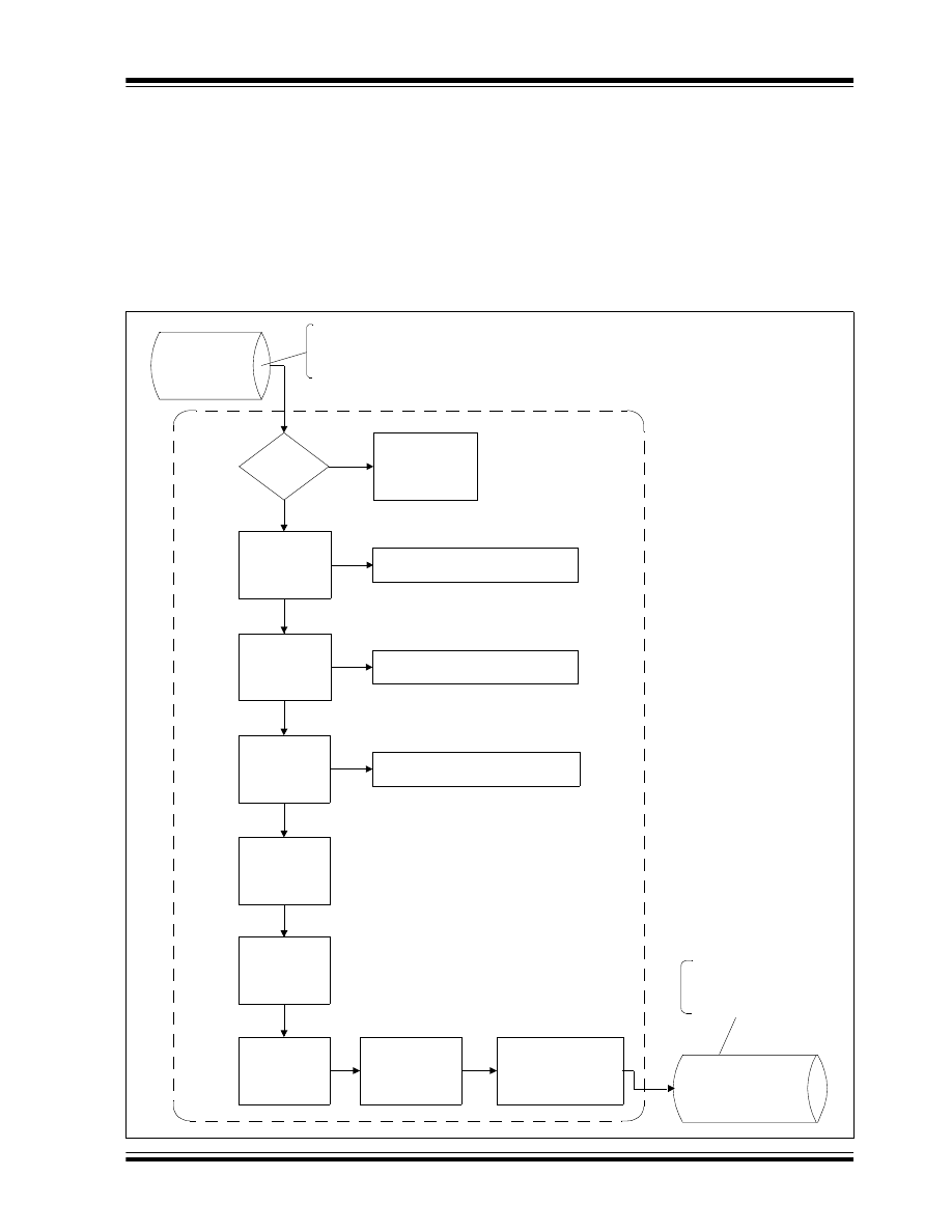
PID Routine Flowcharts
Flowcharts for the PID main routine and the PID
Interrupt Service Routine (ISR) functions are shown in
Figure 3 and Figure 4 (see following pages).
The PID main routine is intended to be called from
the main application code that updates the
error0:error1
variable, as well as the pid_stat1 error
sign bit. Once in the PID main routine, the PID value will
be calculated and put into the
pid_out0:pid_out2
variable, with its sign bit in pid_stat1. The value in
pid_out0:pid_out2
is converted by the application
code to the correct value so that it can be applied to the
Plant.
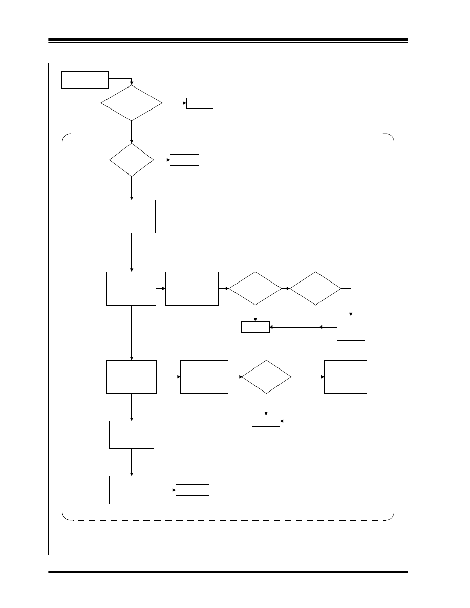
The PID ISR is configured for the PIC18 device’s high
priority interrupt at location 0x0008. The instructions
within this ISR can be placed into an existing ISR, or
kept as is and plugged into the application.
FIGURE 3:
MAIN PID ROUTINE (
PIDMain
)
error0:error1
error
= 0?
Calculate
Proportional Term
Proceed to
GetPidResult
Prop + Integ
NO
PID Action is not
Required, Return to
Main Application
Code
YES
(Prop + Integ) +
Deriv
Scale Down
(Prop + Integ +
Place Final PID Value in
pid_out0:pid_out2
The error is passed from the main
application code to the PID routine,
along with the error sign bit in
pid_stat1
pid_out0:pid_out2
The final PID result is sent to
the main application code,
along with its sign located in
pid_stat1
Calculate Integral
Term
Calculate
Derivative Term
Proportional Gain *
error0:error1
Integral Gain *
a_error0:a_error1
a_error0:a_error1
Derivative Gain *
d_error0:d_error1
Deriv)
AN937
DS00937A-page 6
2004 Microchip Technology Inc.
FIGURE 4:
PID INTERRUPT ROUTINE (
PidInterrupt
)
Has a Timer 1
interrupt occurred?
error
=
0
?
Context Saves
Math Variables
(1)
d_error
=
0
?
Reload
TMR1H:TMR1L,
Clear T1 Flag
Restore Math
RETURN
RETFIE
RETURN
NO
YES
YES
NO
High Priority
Interrupt Occurred
Call
GetDeltaError
error
+
a_error
a_error
=
0
?
NO
YES
a_error
limit
exceeded?
NO
YES
RETURN
Restore
a_error
Limit
YES
NO
RETURN
Set d_err_z bit
Variables
(1)
Note 1:
These instructions are options; they are dependant upon how the ISR is configured. The ISR code
referenced in this application note is set up with context save/restore and is within the main
application code ISR.
Call
GetA_Error
deriv_Count
=
0
? YES
NO
2004 Microchip Technology Inc.
DS00937A-page 7
AN937
Proportional
The proportional term is the simplest of the three and is
also the most commonly found control technique in a
feedback system. The proportional gain (
kp
) is
multiplied by the error. In this application note, the error
is a 16-bit value,
error0:error1
. The amount of
correction applied to the system is directly proportional
to the error. As the gain increases, the applied correc-
tion to the Plant becomes more aggressive. This type
of Controller is common for driving the error to a small,
but non-zero value, leaving a steady state error. This is
the reason for proportional control not being enough in
some systems, thereby requiring integral and deriva-
tive control to come into play, separately or together
(i.e., PI, PD or PID Controller).
IMPLEMENTATION
As mentioned earlier, the proportional is the simplest
term. The error is multiplied by the proportional gain,
error0:error1
*
kp
. This is accomplished by the
16 * 16 multiplication routine. The result is stored in the
24-bit variable,
prop0:prop2
. This value will be used
later in the code to calculate the overall value needed
to go to the Plant.
EQUATION 1:
PROPORTIONAL TERM
Integral
Unlike proportional control, which looks at the present
error, integral control looks at past errors. Given this,
the accumulative error (sum of all past errors) is used
to calculate the integral term, but at fixed time intervals.
Basically, every time the fixed interval expires, the
current error at that moment is added to the
a_error
variable. A temperature system would require a longer
sample period than a motor system because of the
sluggish response in a temperature controlled environ-
ment. If the integral sample period was too fast in the
temperature system, the accumulative error would add
too quickly to give the system a chance to respond,
thereby not allowing it to ever stabilize. Another
element in integral control to consider is ‘wind-up’.
Wind-up occurs when the accumulative error keeps
increasing because the Plant output is saturated. This
event can be avoided by setting limits to the accumula-
tive error. It can also be eliminated by not executing the
integral term when the Plant output is saturated.
Another characteristic is excessive gain, that can
create an unstable condition within the system, causing
it to oscillate. The integral gain must be thoroughly
tested for all possible situations to find the best overall
value. In conclusion, as the accumulative error
increases, the integral term has a greater effect on the
Plant. In a sluggish system, this could dominate the
value that is sent to the Plant.
IMPLEMENTATION
To obtain the integral term, the accumulated error
must be retrieved. The accumulated error
(
a_error0
:
a_error2
) is the sum of past errors. For
this reason, the integral is known for looking at a
system’s history for correction. Refer to Table 2 for
details on how
a_error
is accumulated.
Each time the PID routine receives an error, it may or
may not be added to the accumulated error variable.
This is dependant upon the Timer1 overflow rate. If
Timer1 overflowed, then the error at that moment will
be added to the accumulated error variable. The
Timer1 overflow rate is interrupt driven and is config-
ured as a high priority interrupt. The TMR1H:TMR1L
registers are loaded with values defined by the
constants,
timer1_hi
and
timer1_lo
. The values
for these constants should be based on the Plant’s
response. The accumulated error will be multiplied by
the integral gain,
a_error0
:
a_error2
*
ki
and the
result is stored in
integ0:integ2
.
TABLE 2:
a_error
ACCUMULATION EXAMPLE
prop0:prop2 = kp * error0:error1
Time
Error
Timer1 Overflow
Accumulated Error
t = n
10%
No
x%
t = n + 1
8%
No
x%
t = n + 2
12%
Yes
x + 12%
t = n + 3
9%
No
(x% + 12%)
t = n + 4
6%
No
(x% + 12%)
t = n + 5
4%
Yes
(x% + 12%) + 4%
t = n + ...

AN937
DS00937A-page 8
2004 Microchip Technology Inc.
To avoid integral wind-up, accumulative error limits
were installed (
a_err_1_Lim:a_err_2_Lim
). When
the accumulative error is calculated, the result is com-
pared against the limit variables. If the calculated value
exceeds the limits, the accumulative error is made
equal to the value that is determined by the user in the
variable definition at the beginning of the code.
EQUATION 2:
INTEGRAL TERM
Derivative
As previously mentioned, the proportional term works
on the present error, the integral term works on past
errors and the derivative term works on the present and
past error to forecast a future response of the system.
The derivative term makes an adjustment based on the
rate at which the Plant output is changing from its
Setpoint. A notable characteristic in this type of control
is when the error is constant, or at the maximum limit,
the effect is minimal. There are some systems where
proportional and/or integral do not provide enough
control. In these systems, adding in the derivative term
completes the control requirements.
IMPLEMENTATION
The derivative term is calculated in similar fashion to
the integral term. Considering that the derivative term
is based on the rate at which the system is changing,
the derivative routine calculates
d_error
. This is the
difference between the current error and the previous
error. The rate at which this calculation takes place is
dependant upon the Timer1 overflow. The derivative
term can be extremely aggressive when it is acting on
the error of the system. An alternative to this is to cal-
culate the derivative term from the output of the system
and not the error. In this application note, the error will
be used. To keep the derivative term from being too
aggressive, a derivative counter variable has been
installed. This variable allows d_error to be calculated
once for an x number of Timer1 overflows (unlike the
accumulated error, which is calculated every Timer1
overflow).
To get the derivative term, the previous error is sub-
tracted from the current error (
d_errro0:d_error1
=
error0:error
–
p_error0:p_error1
). The differ-
ence is then multiplied by the derivative gain (
kd
) and
this result is placed in
deriv0:deriv2
, which is
added with the proportional and integral terms.
Tuning
There are several different ways to tune a PID
Controller for system optimization. The code in this
application note is loosely defined, giving it the
flexibility to be tuned for a specific application (i.e.,
motor control, temperature, actuator, etc.).
Tuning a PID Controller can be somewhat difficult and
time consuming and should be completed in a
systematic fashion.
1.
Run the system in an open loop and measure its
response over time. Based on the measured
response, you will get an idea for which PID
term is needed most.
2.
Determine the application requirements: Plant
response time, which PID term will have the
most affect and accumulative error limits.
3.
Determine how often the
a_error
and
d_error
terms should be calculated; this will
dictate the values loaded into the Timer1 and
derivative counter registers.
In the current configuration,
d_error
is calculated
once for every
a_error
calculation. Should this be
less or more, or vice versa? Finally, once these
variables are decided, the PID gains can be
experimented with. Start with the smallest gains (i.e.,
kp
= 1 * 16,
ki
= 1 * 16,
kd
= 1 * 16), slowly
increasing these values until the desired output is
reached. With a few code modifications, it is possible to
make the Controller a proportional only Controller and
tune this to an optimal value. Then it is possible to add
the other terms one at a time, optimizing each time.
EQUATION 3:
DERIVATIVE TERM
integ0:integ2 = ki * a_error0:a_error1 (a_error0:a_error1 = error0:error1 + error0:error1 + …error0:error1)
deriv0:deriv2 = kd * d_error0:d_error1 (d_error0:d_error1 = error0:error – p_error:p_error1)
2004 Microchip Technology Inc.
DS00937A-page 9
AN937
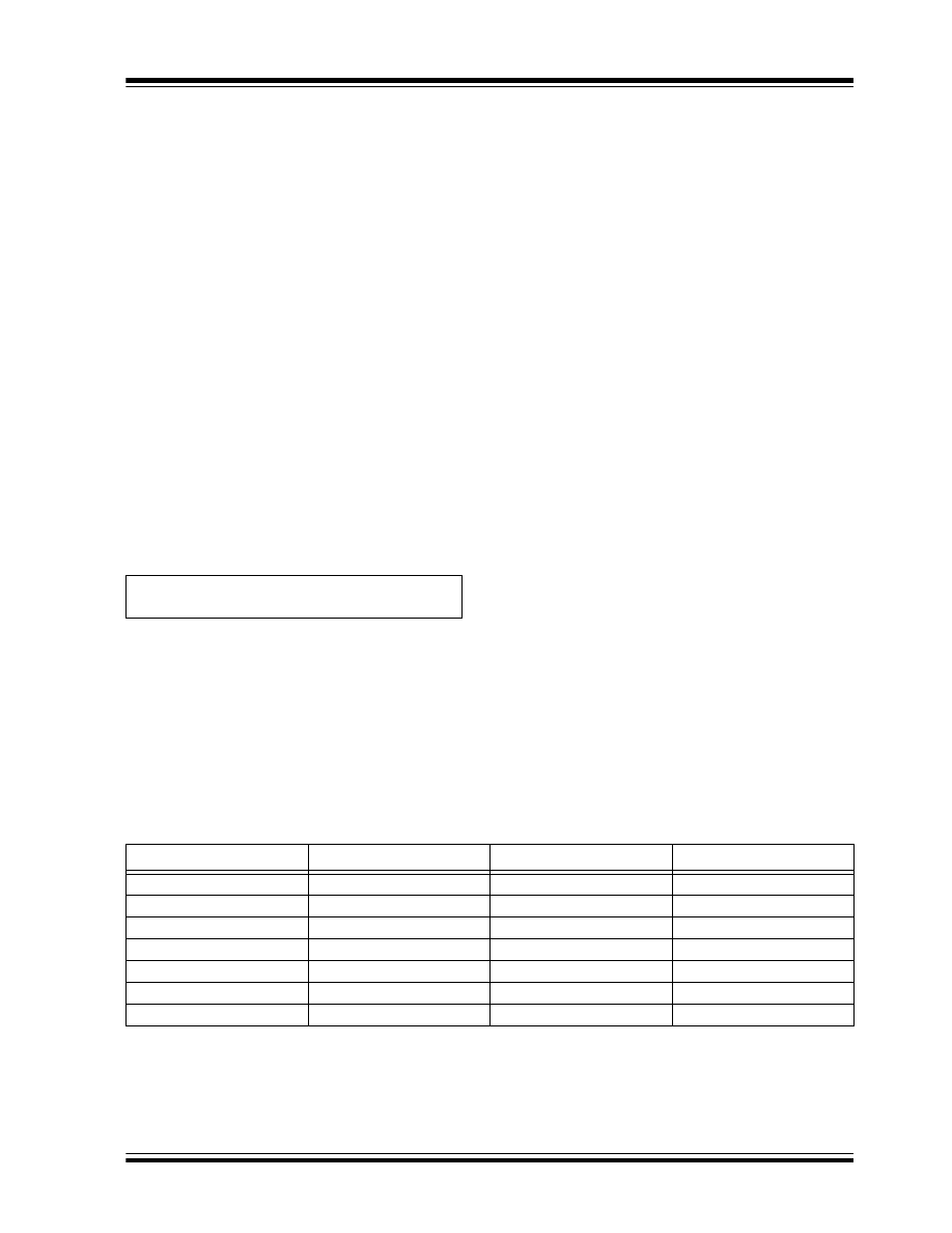
The system response of a temperature controlled
environment is shown in Figures 5 through 7. Figure 5
shows the graphic response for a proportional only
feedback loop. As shown, none of the gain values can
reach the input signal and maintain that level. All four
gain values have settled at a non-zero value, as
previously discussed.
FIGURE 5:
PROPORTIONAL ONLY GRAPHIC RESPONSE
0
0.2
0.4
0.6
0.8
1
1.2
1.4
0
0.5
1
1.5
2
2.5
3
3.5
4
Time
Tem
p
Pgain = 1
Pgain = 2
Pgain = 5
Pgain = 10
Input

AN937
DS00937A-page 10
2004 Microchip Technology Inc.
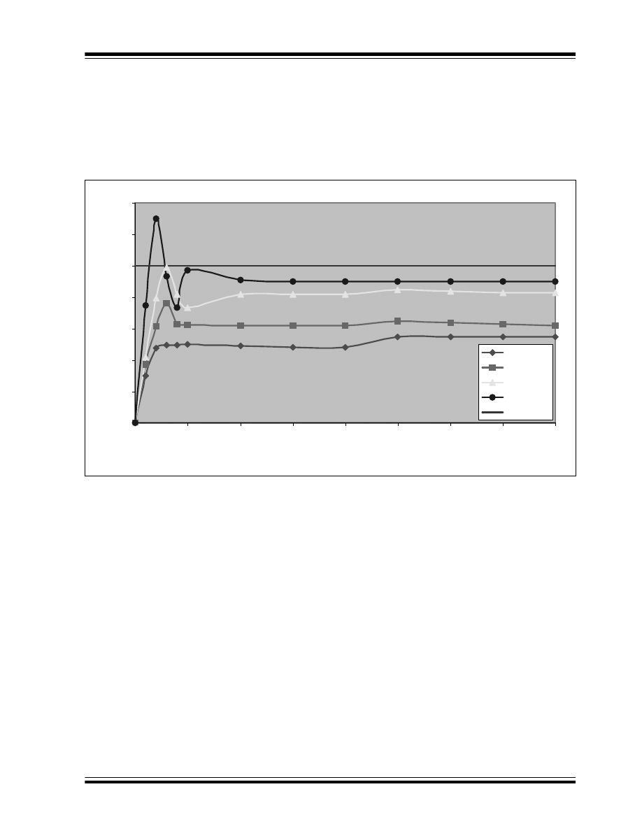
Figure 6 shows the graphic response of a Proportional/
Integral (PI) Controller. The high integral gain
dominates the response (see line with diamond
shapes).
With a tuned proportional and integral gain, the system
does settle to its Setpoint, which is why PI control is
adequate in many systems. The disadvantage is the
time required for it to settle (t = 3), which brings us to
PID control.
FIGURE 6:
PROPORTIONAL/INTEGRAL (PI) CONTROLLER GRAPHIC RESPONSE
0
0.2
0.4
0.6
0.8
1
1.2
1.4
0
1
2
3
4
5
6
Time
Te
m
p
e
ra
tur
e
P = 2, I = 0.1
P = 2, I = 0.05
P = 2, I = 0.02
P = 1, I = 0.02
Input
2004 Microchip Technology Inc.
DS00937A-page 11
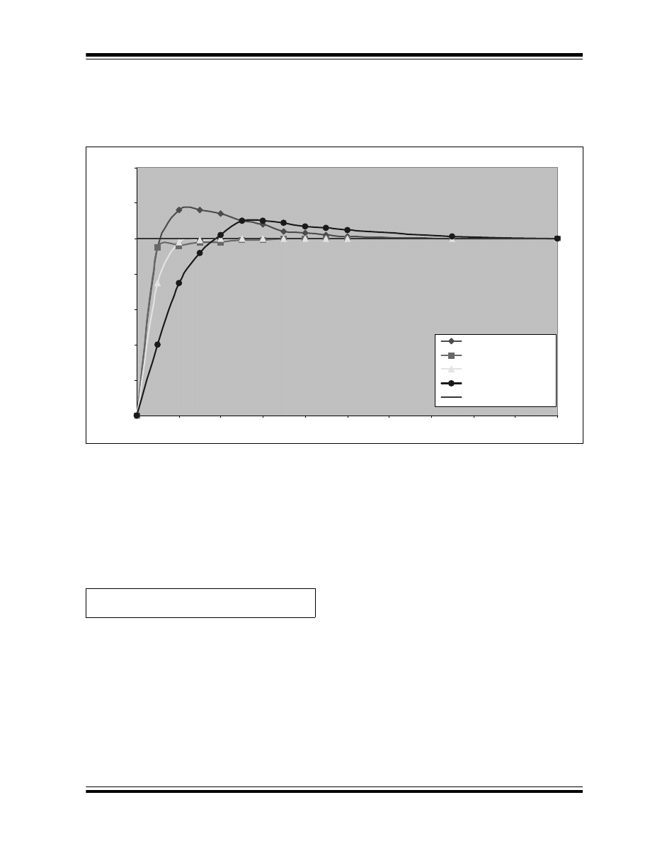
AN937
Figure 7 shows the graphic response of a PID
Controller. This graph is very similar to the PI graph
(Figure 6), except that the PID control takes half as
long as the PI control to settle (t = 1.5) as the Setpoint.
FIGURE 7:
PID CONTROLLER GRAPHIC RESPONSE
PID Output
The PID output is calculated after the proportional,
integral and derivative terms have been determined. In
addition to this calculation is the pid_sign bit, which the
user must check to decide which direction the Plant will
be driven. This bit is located in pid_stat1. The sum of all
these terms is stored in
pid_out0:pid_out2
.
EQUATION 4:
PID ROUTINE
0
0.2
0.4
0.6
0.8
1
1.2
1.4
0
0.2
0.4
0.6
0.8
1
1.2
1.4
1.6
1.8
2
Tim e
T
e
m
p
er
at
u
re
P = 20, I = 0.5, D = 100
P = 20, I = 0.1, D = 100
P = 10, I = 0.1, D = 50
P = 5, I = 0.1, D = 50
Input
PID Output = prop0:prop2 + integ0:integ2 + deriv0:deriv2

AN937
DS00937A-page 12
2004 Microchip Technology Inc.
CONCLUSION
As mentioned in the introduction, the Controller’s
processing capabilities will dictate the system’s ability
to respond to the error. Table 3 shows a list of PID func-
tions, each with the amount of instruction cycles and
time required. In cases where the Plant response is
sluggish, it may be possible to decrease the processor
speed and save on power, but still be able to execute
the PID routine in acceptable time.
TABLE 3:
PID FUNCTIONS
The measurements shown in Table 3 can vary,
depending on the size of the error and how much of the
math routines will be used. The measurements also
reflect an error of 6% sent to the PID routine.
After the code development for this application note
was completed, the PID routine was implemented on
the PIC18F4431 Motor Control board (PICDEM™ MC).
For the initial start of the motor, the PID gains were:
kp
= 96,
ki
= 80 and
kd
= 16. These were scaled
values. After starting the motor and running it close to
its set speed, the integral gain was changed to 144.
The accumulated error was calculated every
millisecond, initiated by a Timer1 overflow. The delta
error (
d_error
) was calculated every 4 ms (derivative
counter = 4).
Function
Instruction Cycles
Elapsed Time (
µ
S) (T
CY
at 40 MHz)
PID Main
437
43.7
Proportional
50
5.0
Integral
52
5.2
Derivative
52
5.2
GetPidResult
270
27
GetA_Error
70
7.0
PID Interrupt
184
18.4

2004 Microchip Technology Inc.
DS00937A-page 13
AN937
APPENDIX A:
SOURCE CODE
The complete source code, including the PID
Application Maestro™ module, any demo applications
and necessary support files, are available for download
as a single archive file from the Microchip corporate
web site at:
www.microchip.com

AN937
DS00937A-page 14
2004 Microchip Technology Inc.
NOTES:

2004 Microchip Technology Inc.
DS00937A-page 15
Information contained in this publication regarding device
applications and the like is intended through suggestion only
and may be superseded by updates. It is your responsibility to
ensure that your application meets with your specifications.
No representation or warranty is given and no liability is
assumed by Microchip Technology Incorporated with respect
to the accuracy or use of such information, or infringement of
patents or other intellectual property rights arising from such
use or otherwise. Use of Microchip’s products as critical
components in life support systems is not authorized except
with express written approval by Microchip. No licenses are
conveyed, implicitly or otherwise, under any intellectual
property rights.
Trademarks
The Microchip name and logo, the Microchip logo, Accuron,
dsPIC, K
EE
L
OQ
, micro
ID
, MPLAB, PIC, PICmicro, PICSTART,
PRO MATE, PowerSmart, rfPIC, and SmartShunt are
registered trademarks of Microchip Technology Incorporated
in the U.S.A. and other countries.
AmpLab, FilterLab, MXDEV, MXLAB, PICMASTER, SEEVAL,
SmartSensor and The Embedded Control Solutions Company
are registered trademarks of Microchip Technology
Incorporated in the U.S.A.
Analog-for-the-Digital Age, Application Maestro, dsPICDEM,
dsPICDEM.net, dsPICworks, ECAN, ECONOMONITOR,
FanSense, FlexROM, fuzzyLAB, In-Circuit Serial
Programming, ICSP, ICEPIC, Migratable Memory, MPASM,
MPLIB, MPLINK, MPSIM, PICkit, PICDEM, PICDEM.net,
PICLAB, PICtail, PowerCal, PowerInfo, PowerMate,
PowerTool, rfLAB, rfPICDEM, Select Mode, Smart Serial,
SmartTel and Total Endurance are trademarks of Microchip
Technology Incorporated in the U.S.A. and other countries.
SQTP is a service mark of Microchip Technology Incorporated
in the U.S.A.
All other trademarks mentioned herein are property of their
respective companies.
© 2004, Microchip Technology Incorporated, Printed in the
U.S.A., All Rights Reserved.
Printed on recycled paper.
Note the following details of the code protection feature on Microchip devices:
•
Microchip products meet the specification contained in their particular Microchip Data Sheet.
•
Microchip believes that its family of products is one of the most secure families of its kind on the market today, when used in the
intended manner and under normal conditions.
•
There are dishonest and possibly illegal methods used to breach the code protection feature. All of these methods, to our
knowledge, require using the Microchip products in a manner outside the operating specifications contained in Microchip’s Data
Sheets. Most likely, the person doing so is engaged in theft of intellectual property.
•
Microchip is willing to work with the customer who is concerned about the integrity of their code.
•
Neither Microchip nor any other semiconductor manufacturer can guarantee the security of their code. Code protection does not
mean that we are guaranteeing the product as “unbreakable.”
Code protection is constantly evolving. We at Microchip are committed to continuously improving the code protection features of our
products. Attempts to break Microchip’s code protection feature may be a violation of the Digital Millennium Copyright Act. If such acts
allow unauthorized access to your software or other copyrighted work, you may have a right to sue for relief under that Act.
Microchip received ISO/TS-16949:2002 quality system certification for
its worldwide headquarters, design and wafer fabrication facilities in
Chandler and Tempe, Arizona and Mountain View, California in
October 2003. The Company’s quality system processes and
procedures are for its PICmicro
®
8-bit MCUs, K
EE
L
OQ
®
code hopping
devices, Serial EEPROMs, microperipherals, nonvolatile memory and
analog products. In addition, Microchip’s quality system for the design
and manufacture of development systems is ISO 9001:2000 certified.

DS00937A-page 16
2004 Microchip Technology Inc.
AMERICAS
Corporate Office
2355 West Chandler Blvd.
Chandler, AZ 85224-6199
Tel: 480-792-7200
Fax: 480-792-7277
Technical Support: 480-792-7627
Web Address: www.microchip.com
Atlanta
3780 Mansell Road, Suite 130
Alpharetta, GA 30022
Tel: 770-640-0034
Fax: 770-640-0307
Boston
2 Lan Drive, Suite 120
Westford, MA 01886
Tel: 978-692-3848
Fax: 978-692-3821
Chicago
333 Pierce Road, Suite 180
Itasca, IL 60143
Tel: 630-285-0071
Fax: 630-285-0075
Dallas
4570 Westgrove Drive, Suite 160
Addison, TX 75001
Tel: 972-818-7423
Fax: 972-818-2924
Detroit
Tri-Atria Office Building
32255 Northwestern Highway, Suite 190
Farmington Hills, MI 48334
Tel: 248-538-2250
Fax: 248-538-2260
Kokomo
2767 S. Albright Road
Kokomo, IN 46902
Tel: 765-864-8360
Fax: 765-864-8387
Los Angeles
18201 Von Karman, Suite 1090
Irvine, CA 92612
Tel: 949-263-1888
Fax: 949-263-1338
San Jose
1300 Terra Bella Avenue
Mountain View, CA 94043
Tel: 650-215-1444
Fax: 650-961-0286
Toronto
6285 Northam Drive, Suite 108
Mississauga, Ontario L4V 1X5, Canada
Tel: 905-673-0699
Fax: 905-673-6509
ASIA/PACIFIC
Australia
Suite 22, 41 Rawson Street
Epping 2121, NSW
Australia
Tel: 61-2-9868-6733
Fax: 61-2-9868-6755
China - Beijing
Unit 706B
Wan Tai Bei Hai Bldg.
No. 6 Chaoyangmen Bei Str.
Beijing, 100027, China
Tel: 86-10-85282100
Fax: 86-10-85282104
China - Chengdu
Rm. 2401-2402, 24th Floor,
Ming Xing Financial Tower
No. 88 TIDU Street
Chengdu 610016, China
Tel: 86-28-86766200
Fax: 86-28-86766599
China - Fuzhou
Unit 28F, World Trade Plaza
No. 71 Wusi Road
Fuzhou 350001, China
Tel: 86-591-7503506
Fax: 86-591-7503521
China - Hong Kong SAR
Unit 901-6, Tower 2, Metroplaza
223 Hing Fong Road
Kwai Fong, N.T., Hong Kong
Tel: 852-2401-1200
Fax: 852-2401-3431
China - Shanghai
Room 701, Bldg. B
Far East International Plaza
No. 317 Xian Xia Road
Shanghai, 200051
Tel: 86-21-6275-5700
Fax: 86-21-6275-5060
China - Shenzhen
Rm. 1812, 18/F, Building A, United Plaza
No. 5022 Binhe Road, Futian District
Shenzhen 518033, China
Tel: 86-755-82901380
Fax: 86-755-8295-1393
China - Shunde
Room 401, Hongjian Building, No. 2
Fengxiangnan Road, Ronggui Town, Shunde
District, Foshan City, Guangdong 528303, China
Tel: 86-757-28395507 Fax: 86-757-28395571
China - Qingdao
Rm. B505A, Fullhope Plaza,
No. 12 Hong Kong Central Rd.
Qingdao 266071, China
Tel: 86-532-5027355 Fax: 86-532-5027205
India
Divyasree Chambers
1 Floor, Wing A (A3/A4)
No. 11, O’Shaugnessey Road
Bangalore, 560 025, India
Tel: 91-80-22290061 Fax: 91-80-22290062
Japan
Benex S-1 6F
3-18-20, Shinyokohama
Kohoku-Ku, Yokohama-shi
Kanagawa, 222-0033, Japan
Tel: 81-45-471- 6166 Fax: 81-45-471-6122
Korea
168-1, Youngbo Bldg. 3 Floor
Samsung-Dong, Kangnam-Ku
Seoul, Korea 135-882
Tel: 82-2-554-7200 Fax: 82-2-558-5932 or
82-2-558-5934
Singapore
200 Middle Road
#07-02 Prime Centre
Singapore, 188980
Tel: 65-6334-8870 Fax: 65-6334-8850
Taiwan
Kaohsiung Branch
30F - 1 No. 8
Min Chuan 2nd Road
Kaohsiung 806, Taiwan
Tel: 886-7-536-4818
Fax: 886-7-536-4803
Taiwan
Taiwan Branch
11F-3, No. 207
Tung Hua North Road
Taipei, 105, Taiwan
Tel: 886-2-2717-7175 Fax: 886-2-2545-0139
EUROPE
Austria
Durisolstrasse 2
A-4600 Wels
Austria
Tel: 43-7242-2244-399
Fax: 43-7242-2244-393
Denmark
Regus Business Centre
Lautrup hoj 1-3
Ballerup DK-2750 Denmark
Tel: 45-4420-9895 Fax: 45-4420-9910
France
Parc d’Activite du Moulin de Massy
43 Rue du Saule Trapu
Batiment A - ler Etage
91300 Massy, France
Tel: 33-1-69-53-63-20
Fax: 33-1-69-30-90-79
Germany
Steinheilstrasse 10
D-85737 Ismaning, Germany
Tel: 49-89-627-144-0
Fax: 49-89-627-144-44
Italy
Via Quasimodo, 12
20025 Legnano (MI)
Milan, Italy
Tel: 39-0331-742611
Fax: 39-0331-466781
Netherlands
Waegenburghtplein 4
NL-5152 JR, Drunen, Netherlands
Tel: 31-416-690399
Fax: 31-416-690340
United Kingdom
505 Eskdale Road
Winnersh Triangle
Wokingham
Berkshire, England RG41 5TU
Tel: 44-118-921-5869
Fax: 44-118-921-5820
05/28/04
Worldwide Sales and Service
Document Outline
- Introduction
- Objectives
- Source Code Overview
- Conclusion
- Appendix A: Source Code
- Worldwide Sales and Service
Wyszukiwarka
Podobne podstrony:
evolving fuzzy rule based controllers using genetik
Auto tuning control using ziegler nichols 1
School Dinner Money (PIC) Microcontroller Projects!; Clive Seager (Electronics Education, 2002)
Gillin Murray, Mind Control Using Holography and Disassociation
Getting Started with PIC Microcontrollers F Stevens (1997) WW(1)
A PIC CONTROLLER FOR GRID CONNECTED PV SYSTEM USING A FPGA BASED INVERTER
Improving Grape Quality Using Microwave Vacuum Drying Associated with Temperature Control (Clary)
A new control strategy for instantaneous voltage compensator using 3 phase PWM inverter
Control Systems Simulation using Matlab and Simulink
implementacja, Controlling
How to build a USB device with PIC 18F4550 or 18F2550 (and the microchip CDC firmware)
Improving Grape Quality Using Microwave Vacuum Drying Associated with Temperature Control (Clary)
Variable Speed Control Of Wind Turbines Using Nonlinear And Adaptive Algorithms
Building Autonomous Line Followers using Arduino and PID
PIC 16C63 Midi controlled Light dimmer schematic
Controlling DC Brushless Motors with PIC17C756A (Microchip AN718, 1999)
Using an Xbox 360 Controller for Windows
Using NLP on Yourself 04 Becoming Masterful at State Control
więcej podobnych podstron