Smiley’s Workshop 14: ALP Temperature Sensor
Smiley’s Workshop 14: Some ALP Sensors
Joe Pardue July 13, 2009
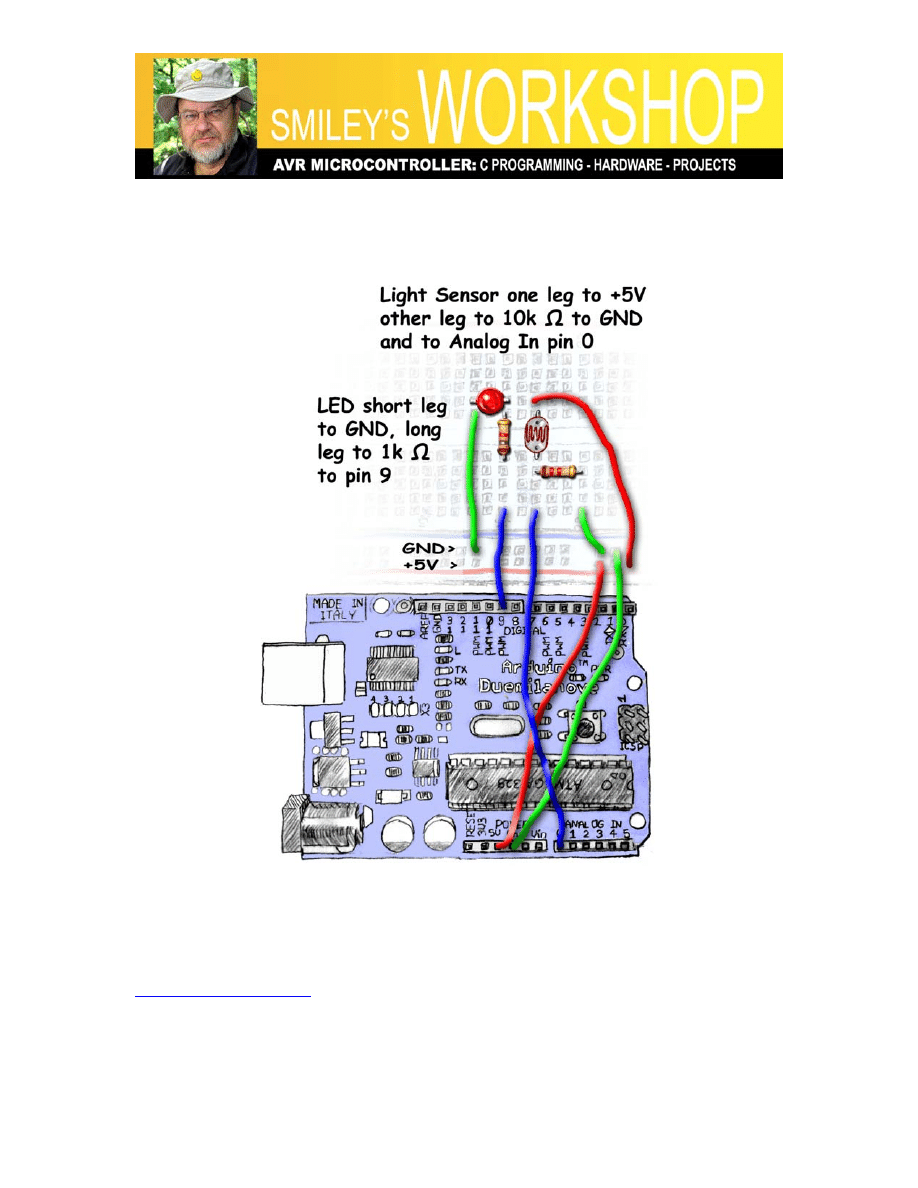
Figure 1: CdS light sensor layout
Recap:
In recent Workshops we’ve been using a new development board and components kit, the
Arduino Duemilanove and the Arduino Projects Kit (available from Nuts&Volts and
) We recognized that The Arduino Way (TAW) is a very simple
and easy way to begin using microcontrollers. And we learned, that while TAW uses a C-
like language, it does not, IMHO, provide a clear path to learning the C or AVR
architecture -- both of which are our long-term goals for this Workshop series, so we
Smiley’s Workshop 14: ALP Temperature Sensor
were introduced to A C Way (ACW) that uses more standard (again IMHO) AVR tools.
We decided to discuss projects using the kit in TAW, but also providing the software
ACW in the Workshop zip file for those ready to move on. After we’ve introduced all the
kit parts, we will then move exclusively to ACW since we will be looking at issues that
are – IMHO - more difficult to accomplish TAW (such as using timer interrupts).
Last month we did learned how to build a command interpreter and how to make
beautiful music (okay – noise) on a piezo element. This month we are going to look at
components from the kit that sense light and temperature.
Light Sensor
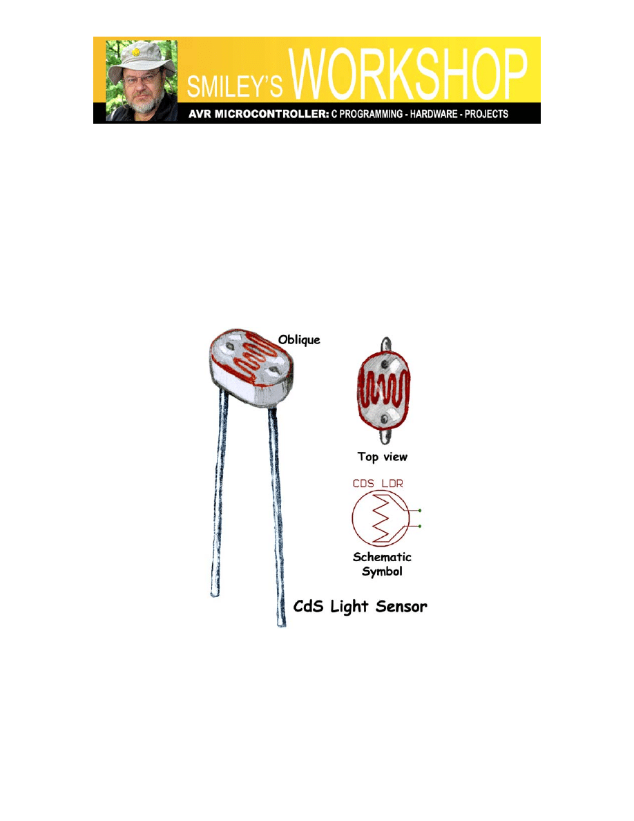
Figure 2: CdS light sensor
Cadmium Sulfide (CdS) has the interesting property that its resistance drops proportional
to the amount of light falling on it. Figure 2: CdS light sensor, shows the sensor in the
Arduino Projects Kit. I’m not going to try to explain how this works since Einstein got a
Nobel Prize for explaining it and apparently even he wasn’t completely correct. In the
dark the resistance is about 138k ohms that drops to about 23k ohms under my work
lights. What you get will of course vary depending on your lights. Theoretically, you
Smiley’s Workshop 14: ALP Temperature Sensor
could use this to make a sensor that outputs some physical measure of light such as
lumens, but the process of calibrating such a sensor to a standard brightness is far more
complex than we want to get into at the moment. So we will simply use our sensor to
recognize changes in light in our specific environment and use those changes to modify
the blink rate of an LED as an indicator of relative brightness.
The source for this code is nearly identical to the AnalogInput example in the Arduino
IDE and the code ported from TAW to ACW in Workshop 12 (you can get that code
from the workshop12.zip file available on
). Try not to get
confused between the AnalogInput example and the code used for the layout in Figure 1:
CdS light sensor layout. In the code the ledPin should be changed to pin 9 and the sensor
pin to Analog In 0. And no, I didn’t move these pins around to confuse you. I did it to
confuse myself. Sorry about that. But it does show how easy it is to change the pins in
either the code or the layouts just as long as you keep them consistent.
Light Sensor Components, Schematic, Layout
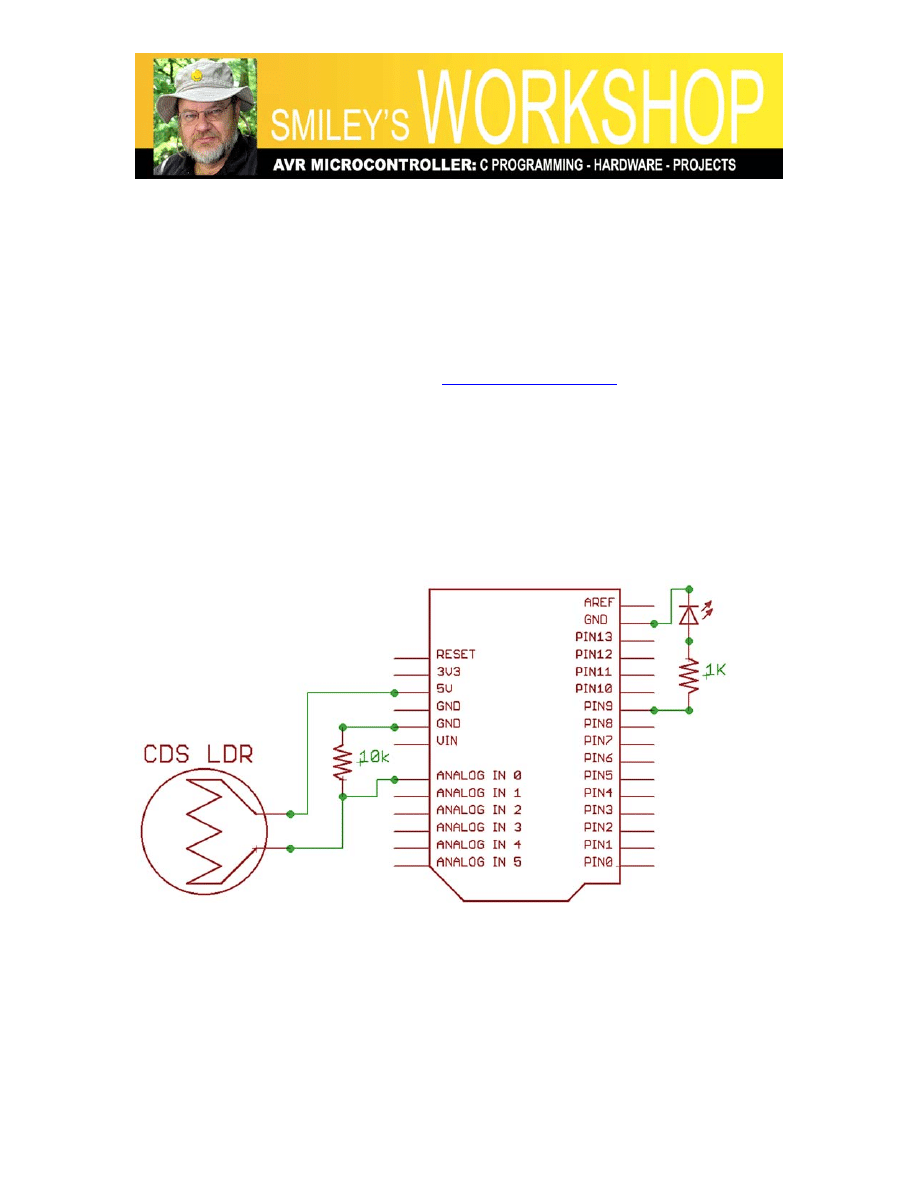
Figure 3: CdS light sensor schematic
You can follow the schematic in Figure 3, and the Layout in Figure 1, to build this light
sensor project hardware. Then modify the Arduino example for Analog Input to conform
to the actual pinout.

Smiley’s Workshop 14: ALP Temperature Sensor
A Word or Two about Storing and Showing Sensor Data
We used the cop-out with the light sensor that calibrating the data to some physical
reference was beyond what we want to do here (and ‘we’ didn’t even ask for your
opinion!) so we let an LED blink at a rate proportional to the sensor output from the
lights in my personal workshop. We can assume that your workshop will be more or less
lighted the same and that you can adjust the code if you live in a cave or on a beach. But
what if we wanted to calibrate the sensor to some actual physical measure of light that
contains, as real physics often does, some fractional data?
There are many situations where we don’t really care if anybody ever sees any indication
of a sensor output, (like the O2 sensor in our car), since the value is being used inside an
embedded system that percolates along without our help. But sometimes, such as when
we are sensing room temperature, we want the sensor output to have some meaning to us.
Our next project uses the LM35 temperature sensor from the Smiley Micros Arduino
Projects Kit and outputs 10mV per degree Centigrade accurate to 0.5 °C, and while that is
a fun fact, we’d hardly know that the room was too darn hot based on a reading of 0.375
volts (never mind our flop-sweat as a trust-worthy sensor). We want to see that it is
99.5°F [37.5 °C for the rest of the world who can translate the output mV to °C in their
head if they wanted to, but I think Fahrenheit so 99.5 is hot and 37.5 is cold] Anyway the
point is that we want to see something meaningful to us.
A quick introduction to signed decimal numbers
This brings us to an issue with computers. Computers use integers (whole numbers
{0,1,2,3,…}) to manipulate data but we want to see temperatures with decimal fractions:
98 won’t cut it, but 98.6 is a good healthy number. Also the LM35 is accurate to 0.5°C so
why waste good fractional information? In our specific case we use an ADC to measure a
value expressed as a whole number between 0 and 1023, but we will be showing a
temperature such as 98.6°F, with an integer part: ‘98’ a decimal point: ‘.’, and a decimal
part: ‘6’. To further complicate things, our temperature scales also use negative numbers
like the temperature at which nitrogen liquefies: -346
°F
.
Computers store data as whole numbers and they either have special hardware or
software to manipulate this basic whole number data type as other data types such as
negative or decimal numbers. They pretend to work with decimal numbers by storing the
integer part and the decimal part as separate whole numbers. They can be told to consider
a number as signed (can hold positive + and negative -) numbers by looking at the most
significant bit of the data [a byte holds 0 to 255, a signed byte ‘holds’ –128 to +127
where the highest bit represents the sign]. All this is by way of introduction, since going

Smiley’s Workshop 14: ALP Temperature Sensor
into the details can get complex quick. We will look at a technique for keeping our data
in the original ADC generated whole numbers (10-bits or 0 to 1023) while presenting that
data to people in a human comprehensible format such as a signed decimal number.
Showing integer data as signed decimal fractions
Our focus in this article is TAW, but to help with some concepts, we need to spend a few
moments ACW. The C programming language has a lot of tools that help the user convert
between data types. We could load our ADC data into double or floating-point data
types, do the math that converts the ADC reading to ‘myTemp = 98.6;’ and then print it
with: printf(“Temperature = %f”,myTemp). We could, that is, if we want to drag along a
couple of extra kilobytes of code to process floating-point data. That is a lot of code
space (expensive in microcontrollers) for a little convenience, so the avr-libc uses several
versions of ‘printf’ that compile to less functional, but much smaller versions for folks
who aren’t interested in the extra data conversion features. The avr-libc default version
when you use printf(“Temperature = %f”,myTemp) will output: “Temperature = ?” since
it, by default, doesn’t do floating point. This causes no end of confusion to novices who
learn C from K&R but then don’t read the avr-libc manual. [Too frequent AVRFreaks
question: “Plz hlp me!!!!!!! I gt a ‘?’ whn I uz printf, why zat?” Too frequent answer:
“RTFM and learn to type!”] You can read all about this in the avr-libc manual, but I
recommend just forgetting about using and printing real floating-point data for the time
being and use the method we’ll discuss in this section which works equally well for TAW
and ACW.
Lets say we want to print the normal human body temperature in Fahrenheit, which
requires a decimal fraction: 98.6 °F. The first trick we use is to keep our body
temperature data stored in integers that are ten times the real value. We thus store 986
rather than 98.6. The second trick is to recover the real value for the integer and decimal
fraction parts only when we want to show the data to people. And the final trick is to
print these two values separately with a decimal point printed between them. We show
the text 98.6 by separately printing the ‘98’ then a decimal point ‘.’ and then the
fractional part ‘6’. We will use the C ‘/’ division and ‘%’ modulo operators to get the
integer and fractional parts of the number.
The ‘/’ division operator in C yields only the integer part of the division so in C 986/10 =
98. The ‘%’ modulo operator yields only the remainder part of a division so in C 986%10
= 6. We can use these operators as follows:
// show 986 as 98.6
whole = 986/10; // divide to get the integer
decimal = 986%10; // modulo to get the fraction
printf("986/10 = %d.%d", whole,decimal);
Smiley’s Workshop 14: ALP Temperature Sensor
And the results output to the terminal would be:
986/10 = 98.6
This technique will also come in handy with TAW since the Serial.println() function
throws away the fractional part of a floating point value so you will have to determine
both the whole and decimal parts and print them with two separate calls to the Serial.Print
function as we will see in a minute.
Converting Centigrade to Fahrenheit
Lets take a moment to look at another issue related to presenting the data specific to
temperature. We are storing raw integers from the ADC that map directly to Centigrade
values (we’ll look at the electrical and microcontroller details in a minute). And, while I
have nothing against °C, I am at the moment sweating to °F, as are many of the readers of
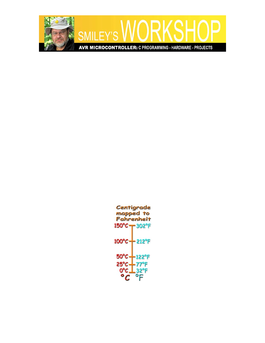
this Workshop. We can use the standard conversion formula:
Fahrenheit = ((9*Centigrade)/5) + 32
This formula maps the data as shown in Figure 4: Centigrade mapped to Fahrenheit, but
be sure and look at the showTemp() function show in ‘LM35_Temperature Source Code’
below since I also round off the data to 0.5 to conform to the sensor accuracy.
Figure 4: Centigrade mapped to Fahrenheit
LM35_Temperature Source Code
The full source code in TAW and ACW for this project is available in Workshop14.zip.

Smiley’s Workshop 14: ALP Temperature Sensor
// LM35_Temperature TAW
// Joe Pardue June 4, 2009
// variable to hold the analog input value
int analogValue = 0;
// variables used to fake the decimal value
int whole = 0;
int decimal = 0;
// For the Arduino using 5V, the ADC measures
// 4.9 mV per unit use 49 to avoid floats
#define ADCUnit 49
void showTemp(int ADCin);
void setup()
{
// begin the serial communication
Serial.begin(9600);
}
void loop()
{
// read the voltage on Analog Pin 0
analogValue = analogRead(0);
// show the reading with faked decimals
showTemp(analogValue);
// delay 1 second before the next reading:
delay(1000);
}
void showTemp(int ADCValue)
{
// print ADC value
Serial.print("1.06 TAW LM35 - raw ADC: ");
Serial.print(ADCValue, DEC);
// make Centigrade
whole = (ADCValue * ADCUnit)/100;
decimal = (ADCValue * ADCUnit)%100;
// round to '0.5'
if(decimal > 50){ decimal = 0; whole +=1;}
else decimal = 5;
// print degrees Centigrade
Serial.print(" > degree C: ");
Serial.print(whole, DEC);
Smiley’s Workshop 14: ALP Temperature Sensor
Serial.print('.');
Serial.print(decimal, DEC);
// convert Centigrade to Fahrenheit
whole = ((9*(ADCValue * ADCUnit))/5)/100;
decimal = ((9*(ADCValue * ADCUnit))/5)%100;
// round to '0.5'
if(decimal > 50){ decimal = 0; whole +=1;}
else decimal = 5;
// print in degrees Fahrenheit
Serial.print(" > degree F: ");
whole += 32; // scale it to °F
Serial.print(whole, DEC);
Serial.print('.');
Serial.println(decimal, DEC);
}
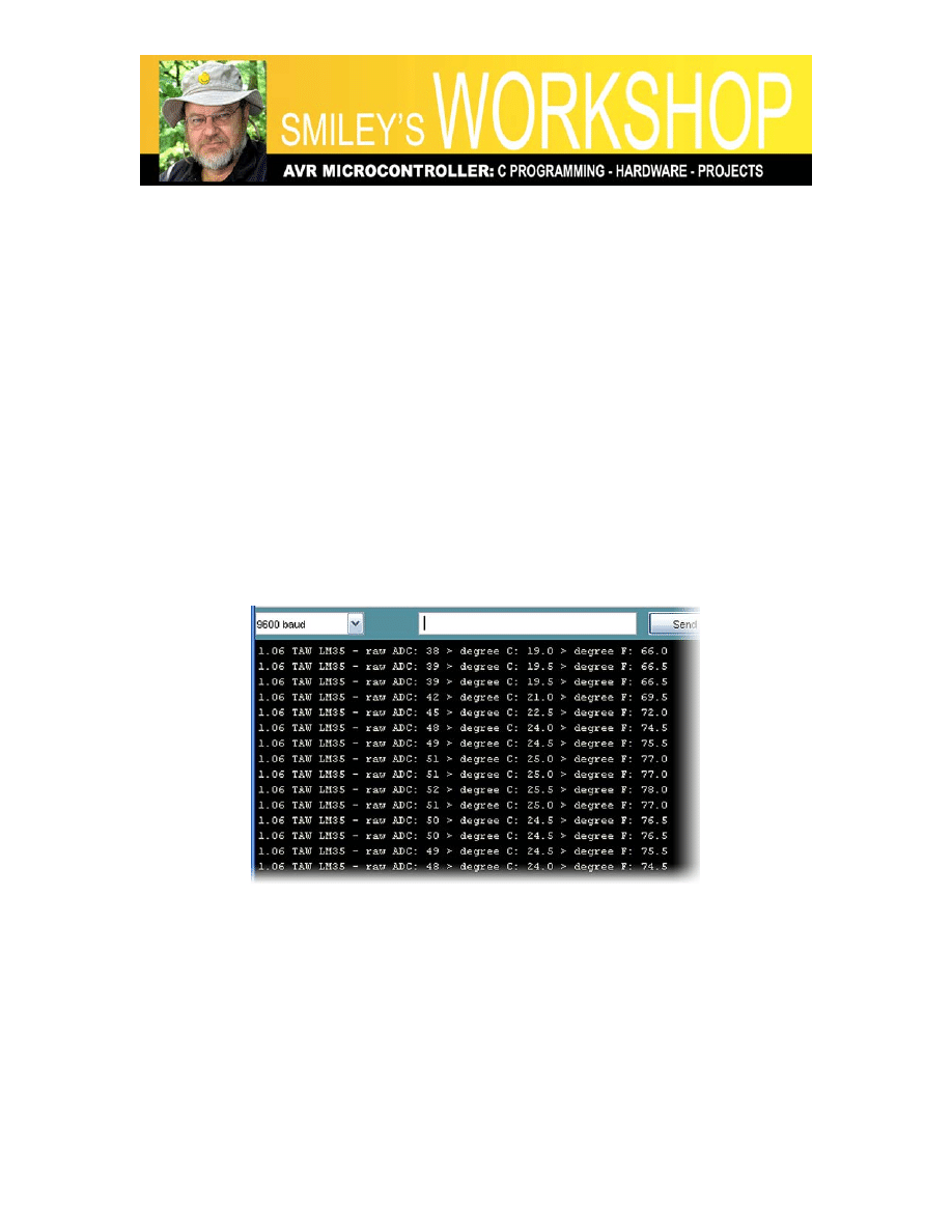
The output of this code in the Arduino IDE serial monitor is shown in Figure 5.
Figure 5: Output in Arduino Serial Monitor
The LM35 Temperature Sensor
Now that we’ve looked at some ideas about how to present integer data with a faked
decimal point, lets look at how to get that data.
The LM35 temperature sensor outputs voltage that is linearly proportional to the
temperature in degrees Celsius (Centigrade). The LM35 datasheet says: “0.5°C accuracy
Smiley’s Workshop 14: ALP Temperature Sensor
guaranteeable at 25°C” and since it outputs 10mV per °C (5mV per 0.5°C), if we can
measure the voltage with an accuracy of 5mV we will match the LM35 accuracy.
Our 10-bit ADC will map an input voltage from 0 to 5 volts to integers from 0 to 1023.
The resolution is 5 V / 1024 ADCunits = .0049V/ADCunit (.0049V is 4.9mV). The
LM35 accurately outputs 5mV per °C and the ADC measures 4.9mV per ADCunit, so
our AVR ADC is well matched with the LM35 for accuracy.
But, as we’ve discussed above, we don’t want to mess with decimal fractions. So first we
note that 4.9mV is .0049 volts so we will multiply our per ADC unit by 10,000 giving use
the whole number 49 for each ADC unit and this is the value we will store [thus the
ADCUnit used in the source code].
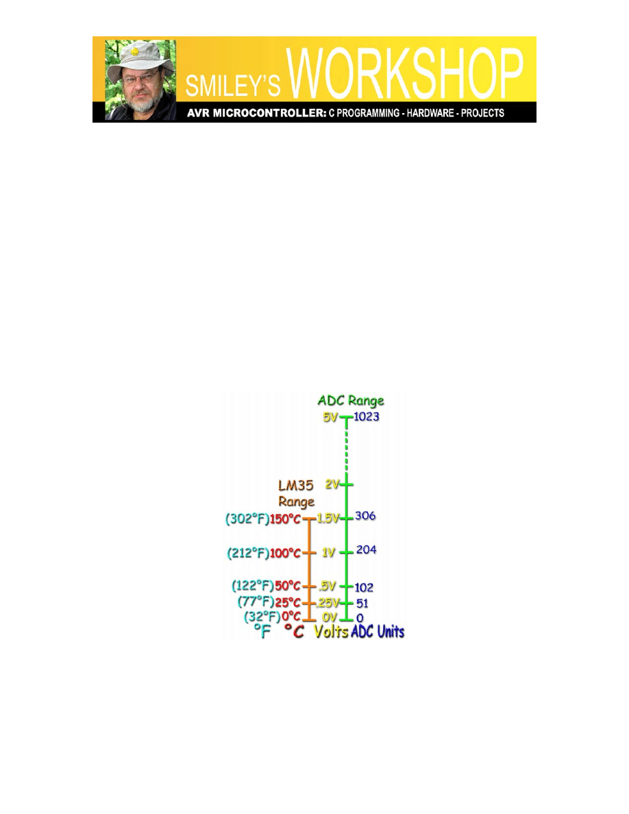
For example, if the ADC reads 204 (out of a maximum of 1023), we multiple 49*204 =
9996, which is the integer that we store. We will only extract the decimal temperature
when we want to show it. In this case, the actual temperature is 100°C or 212°F as shown
in Figure 6: Temperature, voltage, and ADC ranges.
Figure 6: Temperature, voltage, and ADC ranges
Smiley’s Workshop 14: ALP Temperature Sensor
Temperature Sensor Components, Schematic, Layout
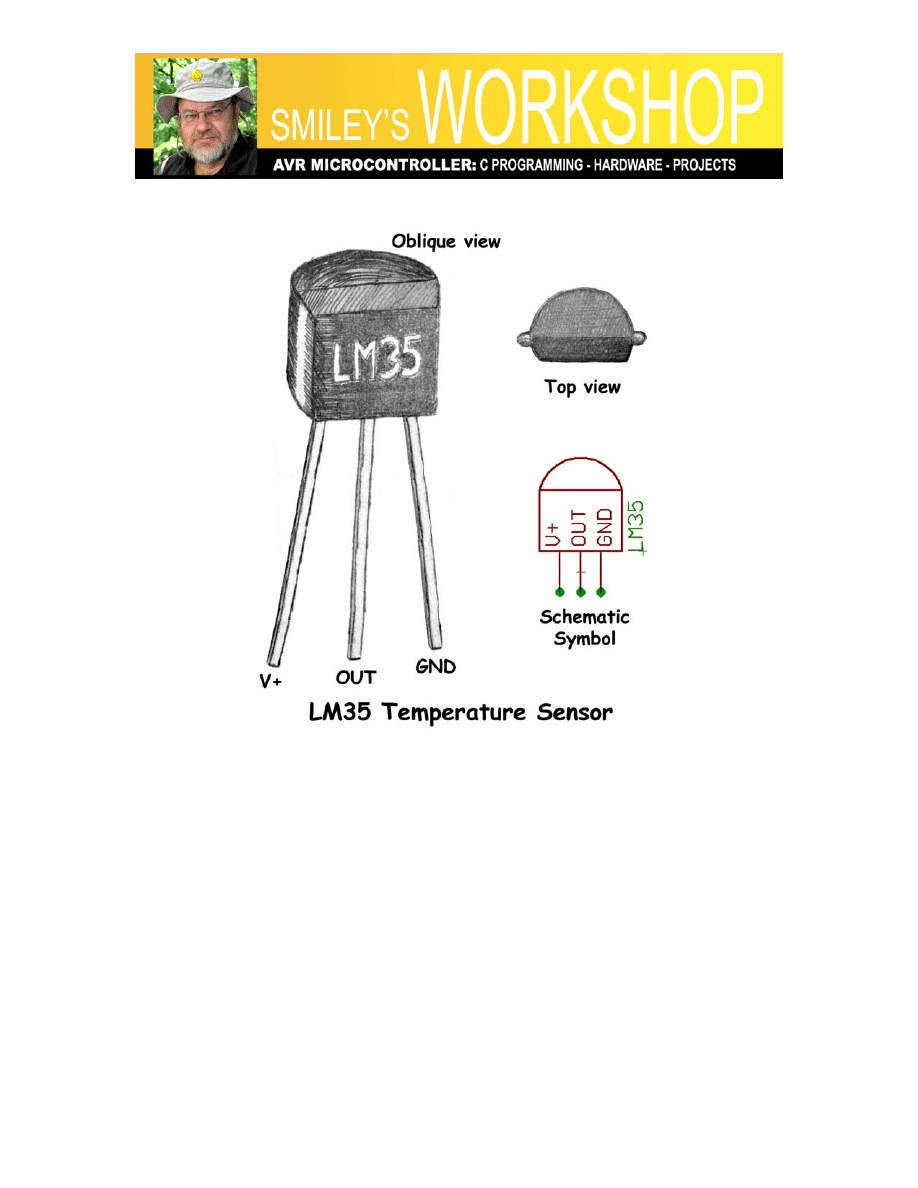
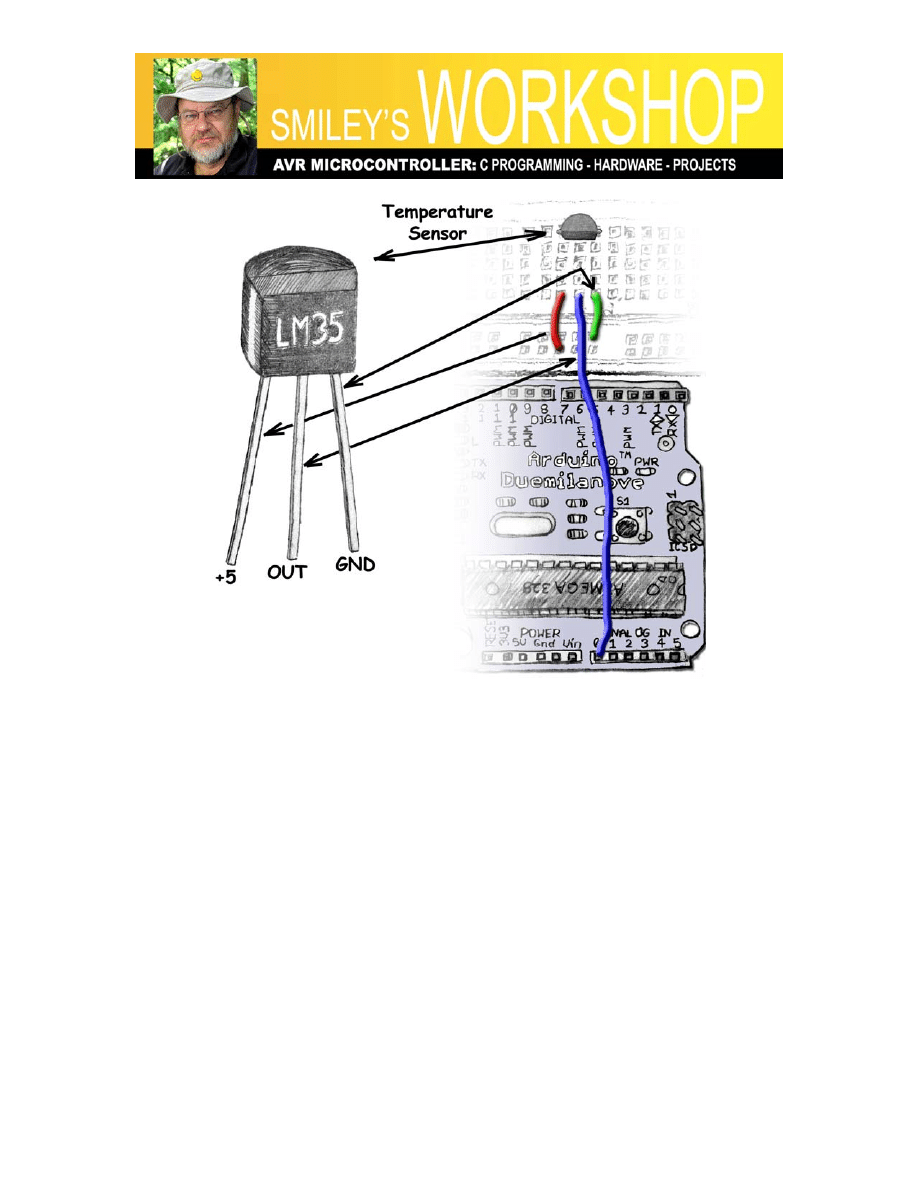
Figure 7: LM35 temperature sensor
The hardware construction is fairly simple for this project. Figure 7: LM35 temperature
sensor, shows the device we will be using, Figure 8: Temperature sensor schematic,
shows how we will hook it up using just three wires for +5V, GND, and Analog Pin 0 as
shown in Figure 9: Temperature sensor layout drawing.
Once you get this working you can do a quick experiment to demonstrate the lag in the
measured temperature and the external temperature. It takes a few seconds for the
external temperature to move from the surface of the LM35 to the sensor. You can see
this by observing the room temperature output, then lightly squeeze the LM35 between
your thumb and index finger. As shown in Figure 5: Output in Arduino Serial Monitor, it
takes a couple of seconds to begin to respond and once you remove your fingers it takes
several seconds, depending on how long you held it, for it to get back to room
temperature. In my case it took a minute or so to go from the frigid 66.0 °F (in the local
bookstore where I tested it over a cup of too expensive tea) to a maximum of 85.0 °F. I
Smiley’s Workshop 14: ALP Temperature Sensor
don’t think this low temperature indicates anything about my zombihood, since the 98.6
°F would require sticking the LM35 into a convenient orifice, something I’m not willing
to do in public. (The lady at the next table is giving me strange looks, possibly because of
my laptop/ALP setup and possibly because I just laughed out loud).
Okay, too much fun for one month. Next month we’ll look at infrared object detection
using the QRD1114 from the Arduino Projects Kits part, and we’ll learn what a bunnies
and snakes have to do with counting tomato soup cans.
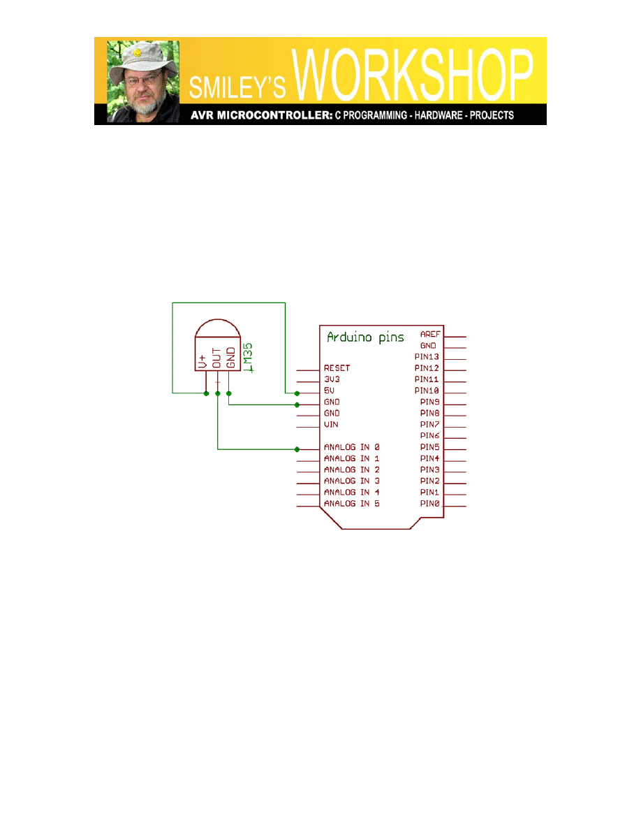
Figure 8: Temperature sensor schematic
Smiley’s Workshop 14: ALP Temperature Sensor
Figure 9: Temperature sensor layout drawing
The Arduino Projects Kit:
Smiley Micros and Nuts&Volts are selling a special kit: The Arduino Projects Kit.
Beginning with Workshops 9 we started learning simple ways to use these components,
and in later Workshops we will use them to drill down into the deeper concepts of C
programming, AVR microcontroller architecture, and embedded systems principles.
With the components in this kit you can:
• Blink 8 LEDs (Cylon Eyes)
• Read a pushbutton and 8-bit DIP switch
• Sense Voltage, Light, and Temperature
• Make Music on a piezo element
• Sense edges and gray levels
• Optically isolate voltages
• Fade LED with PWM
• Control Motor Speed
• And more…

Smiley’s Workshop 14: ALP Temperature Sensor
And a final note: the USB serial port on the Arduino uses the FTDI FT232R chip was
discussed in detail in the article “The Serial Port is Dead, Long Live the Serial Port’ by
yours truly in the June 2008 issue of Nuts&Volts.
You can also get the book “Virtual
Serial Programming Cookbook” (also by yours truly) and associated projects kit from
either Nuts&Volts or Smiley Micros.
LINKS: You can find the source code and supplements for this article in Workshop14.zip
on the Nuts&Volts and Smiley Micros websites.
Document Outline
- Smiley’s Workshop 14: Some ALP Sensors
Wyszukiwarka
Podobne podstrony:
eim4 14 worksheet
eim2 14 worksheet
eim1 14 worksheet
islcollective worksheets grundstufe a1 grundstufe a2 grundschule klassen 14 haupt und realschule kla
islcollective worksheets grundstufe a1 grundstufe a2 mittelstufe b1 mittelstufe b2 grundschule klass
islcollective worksheets grundstufe a1 grundstufe a2 grundschule klassen 14 haupt und realschule kla
islcollective worksheets grundstufe a1 grundstufe a2 grundschule klassen 14 haupt und realschule kla
islcollective worksheets grundstufe a1 vorschule grundschule klassen 14 haupt und realschule klassen
islcollective worksheets grundstufe a1 grundstufe a2 vorschule grundschule klassen 14 sprechen fr li
islcollective worksheets grundstufe a1 grundstufe a2 grundschule klassen 14 haupt und realschule kla
islcollective worksheets grundstufe a1 grundstufe a2 grundschule klassen 14 haupt und realschule kla
islcollective worksheets grundstufe a1 grundschule klassen 14 haupt und realschule klassen 513 erwac
CE Elementary module 14 web worksheet
wyklad 14
Vol 14 Podst wiedza na temat przeg okr 1
Metoda magnetyczna MT 14
wyklad 14 15 2010
więcej podobnych podstron