
Interconnection-
Introduction
This note, originally written in 1985, continues to be
one of our most useful references. It’s popularity stems
from the continual and perpetual difficulty of hooking
up audio equipment without suffering through all sorts
of bizarre noises, hums, buzzes, whistles, etc.— not to
mention the extreme financial, physical and psycholog-
ical price. As technology progresses it is inevitable that
electronic equipment and its wiring should be subject
to constant improvement. Many things have improved
in the audio industry since 1985, but unfortunately
wiring isn’t one of them. However, finally the Audio
Engineering Society (AES) has issued a standards
document for interconnection of pro audio equip-
ment. It is AES48, titled “AES48-2005: AES standard
on interconnections —Grounding and EMC practices
— Shields of connectors in audio equipment containing
active circuitry.”
Rane’s policy is to accommodate rather than dic-
tate. However, this document contains suggestions for
external wiring changes that should ideally only be
implemented by trained technical personnel. Safety
regulations require that all original grounding means
provided from the factory be left intact for safe op-
eration. No guarantee of responsibility for incidental
or consequential damages can be provided. (In other
words, don’t modify cables, or try your own version of
grounding unless you really understand exactly what
type of output and input you have to connect.)
Rane Technical Staff
RaneNote 110
© 1985, 1995, 2006, 2007 Rane Corporation
Sound System
Interconnection
• Cause & prevention of ground loops
• Interfacing balanced & unbalanced
• Proper pin connections and wiring
• Chassis ground vs. signal ground
• Ground lift switches
RaneNote
SOUND SYSTEM INTERCONNECTION
Interconnection-
Ground Loops
Almost all cases of noise can be traced directly to
ground loops, grounding or lack thereof. It is important
to understand the mechanism that causes grounding
noise in order to effectively eliminate it. Each compo-
nent of a sound system produces its own ground in-
ternally. This ground is usually called the audio signal
ground. Connecting devices together with the inter-
connecting cables can tie the signal grounds of the two
units together in one place through the conductors in
the cable. Ground loops occur when the grounds of the
two units are also tied together in another place: via
the third wire in the line cord, by tying the metal chas-
sis together through the rack rails, etc. These situations
create a circuit through which current may flow in a
closed “loop” from one unit’s ground out to a second
unit and back to the first. It is not simply the presence
of this current that creates the hum—it is when this
current flows through a unit’s audio signal ground that
creates the hum. In fact, even without a ground loop, a
little noise current always flows through every inter-
connecting cable (i.e., it is impossible to eliminate these
currents entirely). The mere presence of this ground
loop current is no cause for alarm if your system uses
properly implemented and completely balanced inter-
connects, which are excellent at rejecting ground loop
and other noise currents. Balanced interconnect was
developed to be immune to these noise currents, which
can never be entirely eliminated. What makes a ground
loop current annoying is when the audio signal is af-
fected. Unfortunately, many manufacturers of balanced
audio equipment design the internal grounding system
improperly, thus creating balanced equipment that is
not immune to the cabling’s noise currents. This is one
reason for the bad reputation sometimes given to bal-
anced interconnect.
A second reason for balanced interconnect’s bad
reputation comes from those who think connecting
unbalanced equipment into “superior” balanced equip-
ment should improve things. Sorry. Balanced inter-
connect is not compatible with unbalanced. The small
physical nature and short cable runs of completely
unbalanced systems (home audio) also contain these
ground loop noise currents. However, the currents in
unbalanced systems never get large enough to affect
the audio to the point where it is a nuisance. Mixing
balanced and unbalanced equipment, however, is an
entirely different story, since balanced and unbalanced
interconnect are truly not compatible. The rest of this
note shows several recommended implementations for
all of these interconnection schemes.
The potential or voltage which pushes these noise
currents through the circuit is developed between the
independent grounds of the two or more units in the
system. The impedance of this circuit is low, and even
though the voltage is low, the current is high, thanks to
Mr. Ohm, without whose help we wouldn’t have these
problems. It would take a very high resolution ohm
meter to measure the impedance of the steel chassis or
the rack rails. We’re talking thousandths of an ohm. So
trying to measure this stuff won’t necessarily help you.
We just thought we’d warn you.
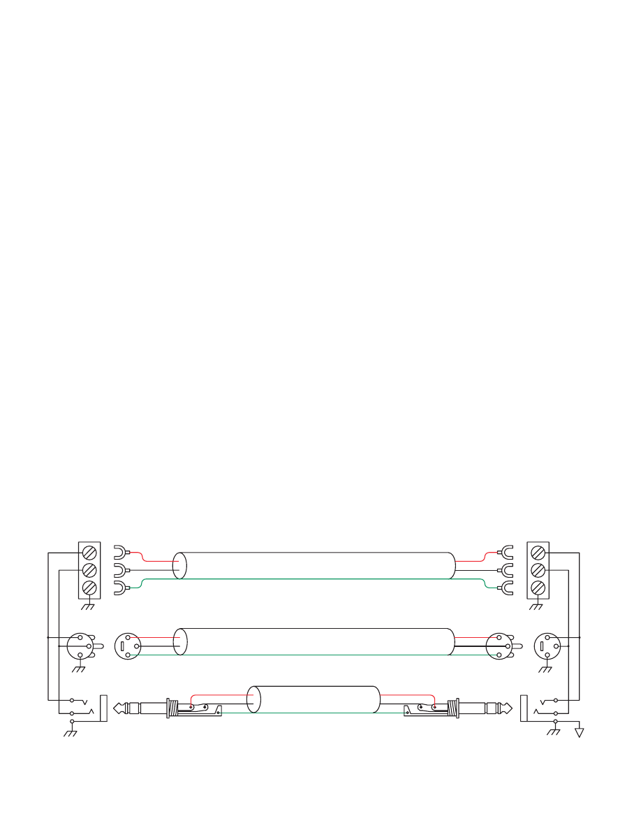
Figure 1a. The right way to do it.
+
–
G
T
R
S
RED
BLACK
2-CONDUCTOR SHIELDED CABLE
2-CONDUCTOR SHIELDED CABLE
2-CONDUCTOR SHIELDED CABLE
SHIELD
RED
BLACK
SHIELD
RED
BLACK
SHIELD
RED
BLACK
SHIELD
RED
BLACK
SHIELD
RED
BLACK
SHIELD
CHASSIS
GROUND
CHASSIS
GROUND
SIGNAL
GROUND
S
R
T
G
–
+
BALANCED OUTPUTS
BALANCED INPUTS
MALE
FEMALE
MALE
FEMALE
1
2
3
C
1
3
2
2
C
3
1
2
1
3

Interconnection-
The Absolute Best Right Way To Do It
The method specified by AES48 is to use balanced lines
and tie the cable shield to the metal chassis (right where
it enters the chassis) at both ends of the cable.
A balanced line requires three separate conduc-
tors, two of which are signal (+ and –) and one shield
(see Figure 1a). The shield serves to guard the sensitive
audio lines from interference. Only by using balanced
line interconnects can you guarantee (yes, guarantee)
hum-free results. Always use twisted pair cable. Chas-
sis tying the shield at each end also guarantees the best
possible protection from RFI [radio frequency interfer-
ence] and other noises [neon signs, lighting dimmers].
Neil Muncy
1
, an electroacoustic consultant and
seasoned veteran of years of successful system design,
chairs the AES Standards Committee (SC-05-05)
working on this subject. He tirelessly tours the world
giving seminars and dispensing information on how to
successfully hook-up pro audio equipment
2
. He makes
the simple point that it is absurd that you cannot go
out and buy pro audio equipment from several different
manufacturers, buy standard off-the-shelf cable assem-
blies, come home, hook it all up and have it work hum
and noise free. Plug and play. Sadly, almost never is
this the case, despite the science and rules of noise-free
interconnect known and documented for over 60 years
(see References for complete information).
It all boils down to using balanced lines, only bal-
anced lines, and nothing but balanced lines. This is why
they were developed. Further, that you tie the shield to
the chassis, at the point it enters the chassis, and at both
ends of the cable (more on ‘both ends’ later).
Since standard XLR cables come with their shields
tied to pin 1 at each end (the shells are not tied, nor
need be), this means equipment using 3-pin, XLR-type
connectors must tie pin 1 to the chassis (usually called
chassis ground) — not the audio signal ground as is
most common.
Figure 1b. Recommmended practice.
CASE
(+)
(–)
COMMON (WRONG) PRACTICE
RECOMMENDED PRACTICE
(–)
(+)
OPTIONAL
CASE
1
2
3
3
1
2
CHASSIS
GROUND
SIGNAL
GROUND
CHASSIS
GROUND
CHASSIS
GROUND
Not using signal ground is the most radical depar-
ture from common pro-audio practice. Not that there
is any argument about its validity. There isn’t. This is
the right way to do it. So why doesn’t audio equipment
come wired this way? Well, some does, and since 1993,
more of it does. That’s when Rane started manufac-
turing some of its products with balanced inputs and
outputs tying pin 1 to chassis. So why doesn’t everyone
do it this way? Because life is messy, some things are
hard to change, and there will always be equipment in
use that was made before proper grounding practices
were in effect.
Unbalanced equipment is another problem: it is
everwhere, easily available and inexpensive. All those
RCA and ¼" TS connectors found on consumer equip-
ment; effect-loops and insert-points on consoles; signal
processing boxes; semi-pro digital and analog tape
recorders; computer cards; mixing consoles; et cetera.
The next several pages give tips on how to suc-
cessfully address hooking up unbalanced equipment.
Unbalanced equipment when “blindly” connected with
fully balanced units starts a pattern of hum and unde-
sirable operation, requiring extra measures to correct
the situation.
The Next Best Right Way To Do It
The quickest, quietest and most foolproof method to
connect balanced and unbalanced is to transformer
isolate all unbalanced connections. See Figure 2.
Many manufacturers provide several tools for this
task, including Rane. Consult your audio dealer to ex-
plore the options available.
The goal of these adaptors is to allow the use of
standard cables. With these transformer isolation
boxes, modification of cable assemblies is unnecessary.
Virtually any two pieces of audio equipment can be
successfully interfaced without risk of unwanted hum
and noise.
Figure 2. Transformer Isolation
NOT CONNECTED
AT CHASSIS
(PLASTIC JACK)
EARTH GROUNDED
METAL ENCLOSURE
CHASSIS IS
GROUNDED TO PIN 1
1/4”
TIP-SLEEVE
CASE LUG MAY
CONNECT TO
CHASSIS
(NOT REQUIRED)
TRANSFORMER
UNBALANCED
BALANCED
3
1
2

Interconnection-
Another way to create the necessary isolation is to
use a direct box. Originally named for its use to convert
the high impedance, high level output of an electric
guitar to the low impedance, low level input of a re-
cording console, it allowed the player to plug “directly”
into the console. Now this term is commonly used to
describe any box used to convert unbalanced lines to
balanced lines.
The Last Best Right Way To Do It
If transformer isolation is not an option, special
cable assemblies are a last resort. The key here is to
prevent the shield currents from flowing into a unit
whose grounding scheme creates ground loops (hum)
in the audio path (i.e., most audio equipment).
It is true that connecting both ends of the shield is
theoretically the best way to interconnect equipment
–though this assumes the interconnected equipment is
internally grounded properly. Since most equipment is
not internally grounded properly, connecting both ends
of the shield is not often practiced, since doing so usu-
ally creates noisy interconnections.
A common solution to these noisy hum and buzz
problems involves disconnecting one end of the shield,
even though one can not buy off-the-shelf cables with
the shield disconnected at one end. The best end to dis-
connect is the receiving end. If one end of the shield is
disconnected, the noisy hum current stops flowing and
away goes the hum — but only at low frequencies. A
ground-sending-end-only shield connection minimizes
the possibility of high frequency (radio) interference
since it prevents the shield from acting as an antenna
to the next input. Many reduce this potential RF inter-
ference by providing an RF path through a small ca-
pacitor (0.1 or 0.01 microfarad ceramic disc) connected
from the lifted end of the shield to the chassis. (This is
referred to as the “hybrid shield termination” where the
sending end is bonded to the chassis and the receiving
end is capacitively coupled. See Neutrik’s EMC-XLR
for example.) The fact that many modern day install-
ers still follow this one-end-only rule with consistent
success indicates this and other acceptable solutions to
RF issues exist, though the increasing use of digital and
wireless technology greatly increases the possibility of
future RF problems.
If you’ve truly isolated your hum problem to a spe-
cific unit, chances are, even though the documentation
indicates proper chassis grounded shields, the suspect
unit is not internally grounded properly. Here is where
special test cable assemblies, shown in Figure 3, really
come in handy. These assemblies allow you to connect
the shield to chassis ground at the point of entry, or to
pin 1, or to lift one end of the shield. The task becomes
more difficult when the unit you’ve isolated has multi-
ple inputs and outputs. On a suspect unit with multiple
cables, try various configurations on each connection
to find out if special cable assemblies are needed at
more than one point.
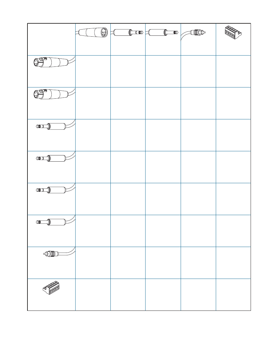
See Figure 4 for suggested cable assemblies for your
particular interconnection needs. Find the appropri-
ate output configuration (down the left side) and then
match this with the correct input configuration (across
the top of the page.) Then refer to the following pages
for a recommended wiring diagram.
Ground Lifts
Many units come equipped with ground lift switches.
In only a few cases can it be shown that a ground lift
switch improves ground related noise. (Has a ground
lift switch ever really worked for you?) In reality, the
presence of a ground lift switch greatly reduces a unit’s
ability to be “properly” grounded and therefore im-
mune to ground loop hums and buzzes. Ground lifts
are simply another Band-Aid
®
to try in case of ground-
ing problems. It is true that an entire system of prop-
erly grounded equipment, without ground lift switches,
is guaranteed (yes guaranteed) to be hum free. The
problem is most equipment is not (both internally and
externally, AC system wise) grounded properly.
Most units with ground lifts are shipped so the unit
is “grounded” — meaning the chassis is connected to
audio signal ground. (This should be the best and is
the “safest” position for a ground lift switch.) If after
hooking up your system it exhibits excessive hum or
Figure 3. Test cable
TEST
WIRE
GROUND CLIP
FEMALE
MALE
1
C
2
3
1
2
3
RED
BLACK
SHIELD
RED
BLACK
SHIELD
2-CONDUCTOR SHIELDED CABLE

Interconnection-
buzzing, there is an incompatibility somewhere in the
system’s grounding configuration. In addition to these
special cable assemblies that may help, here are some
more things to try:
1. Try combinations of lifting grounds on units sup-
plied with lift switches (or links). It is wise to do this
with the power off!
2. If you have an entirely balanced system, verify all
chassis are tied to a good earth ground, for safety’s
sake and hum protection. Completely unbalanced
systems never earth ground anything (except cable
TV, often a ground loop source). If you have a mixed
balanced and unbalanced system, do yourself a favor
and use isolation transformers or, if you can’t do
that, try the special cable assemblies described here
and expect it to take many hours to get things quiet.
May the Force be with you.
3. Balanced units with outboard power supplies (wall
warts or “bumps” in the line cord) do not ground the
chassis through the line cord. Make sure such units
are solidly grounded by tying the chassis to an earth
ground using a star washer for a reliable contact.
(Rane always provides this chassis point as an exter-
nal screw with a toothed washer.) Any device with
a 3-prong AC plug, such as an amplifier, may serve
as an earth ground point. Rack rails may or may not
serve this purpose depending on screw locations and
paint jobs.
Floating, Pseudo, and Quasi-Balancing
During inspection, you may run across a ¼" output
called floating unbalanced, sometimes also called psue-
do-balanced or quasi-balanced. In this configuration,
the sleeve of the output stage is not connected inside
the unit and the ring is connected (usually through a
small resistor) to the audio signal ground. This allows
the tip and ring to “appear” as an equal impedance,
not-quite balanced output stage, even though the out-
put circuitry is unbalanced.
Floating unbalanced often works to drive either a
balanced or unbalanced input, depending if a TS or
TRS standard cable is plugged into it. When it hums, a
special cable is required. See drawings #11 and #12, and
do not make the cross-coupled modification of tying
the ring and sleeve together.
References
1. Neil A. Muncy, “Noise Susceptibility in Analog and Digi-
tal Signal Processing Systems,” presented at the 97th AES
Convention of Audio Engineering Society in San Fran-
cisco, CA, Nov. 1994.
2. Grounding, Shielding, and Interconnections in Analog
& Digital Signal Processing Systems: Understanding the
Basics; Workshops designed and presented by Neil Muncy
and Cal Perkins, at the 97th AES Convention of Audio
Engineering Society in San Francisco, CA, Nov. 1994.
3. The entire June 1995 AES Journal, Vol. 43, No. 6, available
$6 members, $11 nonmembers from the Audio Engineer-
ing Society, 60 E. 42nd St., New York, NY, 10165-2520.
4. Phillip Giddings, Audio System Design and Installation
(SAMS, Indiana, 1990).
5. Ralph Morrison, Noise and Other Interfering Signals
(Wiley, New York, 1992).
6. Henry W. Ott, Noise Reduction Techniques in Electronic
Systems, 2nd Edition (Wiley, New York, 1988).
7. Cal Perkins, “Measurement Techniques for Debugging
Electronic Systems and Their Instrumentation,” The Pro-
ceedings of the 11th International AES Conference: Audio
Test & Measurement, Portland, OR, May 1992, pp. 82-92
(Audio Engineering Society, New York, 1992).
8. Macatee, RaneNote: “Grounding and Shielding Audio
Devices,” Rane Corporation, 1994.
9. Philip Giddings, “Grounding and Shielding for Sound and
Video,” S&VC, Sept. 20th, 1995.
10. AES48-2005: AES standard on interconnections —
Grounding and EMC practices — Shields of connectors
in audio equipment containing active circuitry (Audio
Engineering Society, New York, 2005).
Band-Aid is a registered trademark of Johnson & Johnson
Winning the Wiring Wars
• Use balanced connections whenever possible, with
the shield bonded to the metal chassis at both ends.
• Transformer isolate all unbalanced connections
from balanced connections.
• Use special cable assemblies when unbalanced lines
cannot be transformer isolated.
• Any unbalanced cable must be kept under 10 feet
(3 m) in length. Lengths longer than this will ampli-
fy all the nasty side effects of unbalanced circuitry's
ground loops.
Summary
If you are unable to do things correctly (i.e. use fully
balanced wiring with shields tied to the chassis at both
ends, or transformer isolate all unbalanced signals
from balanced signals) then there is no guarantee that
a hum-free interconnect can be achieved, nor is there a
definite scheme that will assure noise-free operation in
all configurations.
Interconnection-
Figure 4. Interconnect chart for locating correct cable assemblies on the following pages.
Note: (A) This configuration uses an “off-the-shelf” cable.
Note: (B) This configuration causes a 6 dB signal loss. Compensate by “turning the system up” 6 dB.
To Input
MALE
BALANCED XLR
¼" BALANCED
TRS (TIP-RING-SLEEVE)
¼" OR 3.5mm
UNBALANCED
TS (TIP-SLEEVE)
UNBALANCED RCA
BALANCED
EUROBLOCK
Fr
om Output
1
2
3
4
6
5
2
1
10
9
8
7
12
11
8
7
12
11
22
21
16
23
23
15
14
13
20
24
24
19
18
17
B
B
B
B
A
A
A
A
A
A
FEMALE BALANCED XLR
(NOT A TRANSFORMER,
NOR A CROSS-COUPLED
OUTPUT STAGE)
FEMALE BALANCED XLR
(EITHER A TRANSFORMER
OR A CROSS-COUPLED
OUTPUT STAGE)
¼” BALANCED TRS
(NOT A TRANSFORMER,
NOR A CROSS-COUPLED
OUTPUT STAGE)
¼” BALANCED TRS
(EITHER A TRANSFORMER
OR A CROSS-COUPLED
OUTPUT STAGE)
¼” FLOATING UNBALANCED
TRS (TIP-RING-SLEEVE)
(SLEEVE IN UNIT = NC)
¼” OR 3.5 mm
UNBALANCED
TS (TIP-SLEEVE)
UNBALANCED RCA
(TIP-SLEEVE)
CABLE
CONNECTORS
BALANCED
EUROBLOCK
+
to
+
–
to
–
SHIELD ONLY
TO XLR PIN 1
+
to
+
–
to
–
SHIELD ONLY
TO EUROBLOCK
+
to
+
–
to
–
SHIELD ONLY
TO EUROBLOCK
+
to
+
–
to
–
SHIELD ONLY
TO EUROBLOCK
+
to
+
–
to
–
SHIELD ONLY
TO EUROBLOCK
+
to
+
–
to
–
SHIELD ONLY
TO TRS SLEEVE
+
to
+
–
to
–
GROUND to GROUND
+
to
+
–
to
–
GROUND to GROUND
Interconnection-
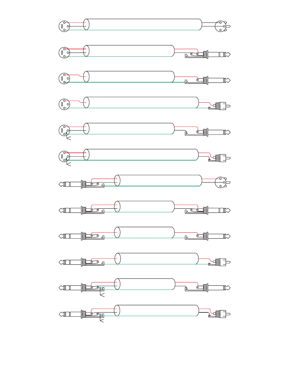
10
9
S=SHIELD
R=NC
T=RED
S=SHIELD
R=NC
T=RED
8
7
S=NC
R=BLACK
T=RED
S=NC
R=BLACK
T=RED
MALE
6
5
3=BLACK
BLACK
4
3
3=NC
2=RED
1=SHIELD
SHIELD
SHIELD
2
FEMALE
1
3=BLACK
2=RED
1=NC
MALE
B
B
B
B
S=SHIELD
R=BLACK
T=RED
S=SHIELD
R=BLACK
T=RED
11
CROSS-COUPLED OUTPUT ONLY: CONNECT PIN 1 TO PIN 3 AT THIS END
AND SET GROUND LIFT SWITCH TO ‘GROUNDED’ (IF PRESENT).
CROSS-COUPLED OUTPUT ONLY: CONNECT PIN 1 TO PIN 3 AT THIS END
AND SET GROUND LIFT SWITCH TO ‘GROUNDED’ (IF PRESENT).
CROSS-COUPLED OUTPUT ONLY: CONNECT RING TO SLEEVE
AT THIS END AND SET GROUND LIFT SWITCH TO ‘GROUNDED’ (IF PRESENT).
1
3
2
3
1
C
2
3
1
C
2
3
1
C
2
3
1
C
2
3
1
C
2
3
1
C
2
1
3
2
To
Input
Fr
om Output
RED
BLACK
RED
BLACK
SHIELD
RED
BLACK
BLACK
FEMALE
FEMALE
3=BLACK
2=RED
1=NC
RED
RED
SHIELD
RED
SHIELD
SHIELD
RED
RED
BLACK
N/C
N/C
N/C
RED
BLACK
RED
SHIELD
N/C
BLACK
RED
BLACK
RED
3=NC
2=RED
1=SHIELD
2=RED
1=SHIELD
3=BLACK
2=RED
1=SHIELD
3=BLACK
2=RED
1=SHIELD
3=BLACK
2=RED
1=SHIELD
SHIELD
FEMALE
FEMALE
FEMALE
RED
SHIELD
RED
BLACK
SHIELD
SHIELD
RED
BLACK
RED
BLACK
BLACK
RED
RED
SHIELD
RED
SHIELD
RED
SHIELD
RED
SHIELD
RED
BLACK
2-CONDUCTOR SHIELDED CABLE
2-CONDUCTOR SHIELDED CABLE
2-CONDUCTOR SHIELDED CABLE
2-CONDUCTOR SHIELDED CABLE
2-CONDUCTOR SHIELDED CABLE
2-CONDUCTOR SHIELDED CABLE
2-CONDUCTOR SHIELDED CABLE
1-CONDUCTOR SHIELDED CABLE
1-CONDUCTOR SHIELDED CABLE
1-CONDUCTOR SHIELDED CABLE
1-CONDUCTOR SHIELDED CABLE
S=SHIELD
R=BLACK
T=RED
S=SHIELD
T=RED
S=SHIELD
T=RED
S=SHIELD
T=RED
S=BLACK
T=RED
S=BLACK
T=RED
S=BLACK
T=RED
S=BLACK
T=RED
12
S=SHIELD
R=BLACK
T=RED
S=BLACK
T=RED
CROSS-COUPLED OUTPUT ONLY: CONNECT RING TO SLEEVE
AT THIS END AND SET GROUND LIFT SWITCH TO ‘GROUNDED’ (IF PRESENT).
BLACK
SHIELD
RED
BLACK
RED
2-CONDUCTOR SHIELDED CABLE
Interconnection-
DOC 102907
©Rane Corporation 00 th Ave. W., Mukilteo WA 9-09 USA TEL --000 FAX -- WEB www.rane.com
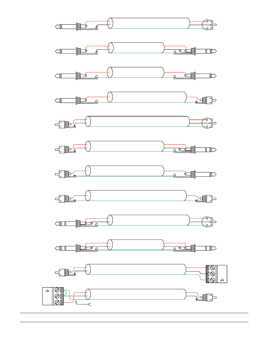
22
21
MALE
(ANY UNBALANCED CONNECTOR)
(ANY UNBALANCED CONNECTOR)
(CHECK: NO STANDARD POLARITY ON EUROBLOCKS)
(CHECK: NO STANDARD POLARITY ON EUROBLOCKS)
20
19
18
17
16
15
MALE
A
14
13
MALE
A
A
A
A
A
1
3
2
1
2
3
1
2
3
To
Input
Fr
om Output
S=SHIELD
R=BLACK
T=RED
S=SHIELD
R=BLACK
T=RED
S=SHIELD
R=BLACK
T=RED
S=SHIELD
R=BLACK
T=RED
S=SHIELD
R=BLACK
T=RED
23
S=BLACK
T=RED
S=BLACK
T=RED
S=BLACK
T=RED
S=BLACK
T=RED
S=SHIELD
T=RED
S=SHIELD
T=RED
S=SHIELD
T=RED
S=SHIELD
T=RED
S=SHIELD
T=RED
S=SHIELD
T=RED
S=SHIELD
T=RED
S=SHIELD
T=RED
3=BLACK
2=RED
1=SHIELD
3=BLACK
2=RED
1=SHIELD
3=BLACK
2=RED
1=SHIELD
SHIELD
BLACK
SHIELD
RED
BLACK
SHIELD
RED
BLACK
RED
SHIELD
SHIELD
BLACK
RED
SHIELD
BLACK
RED
SHIELD
BLACK
RED
SHIELD
BLACK
RED
SHIELD
BLACK
RED
SHIELD
RED
SHIELD
RED
SHIELD
RED
SHIELD
RED
BLACK
RED
N/C
N/C
BLACK
RED
BLACK
RED
BLACK
RED
RED
SHIELD
RED
SHIELD
RED
SHIELD
RED
24
S=BLACK
T=RED
CROSS-COUPLED OUTPUT ONLY: CONNECT BLACK TO SHIELD AT THIS END
AND SET GROUND LIFT SWITCH TO ‘GROUNDED’ (IF PRESENT).
BLACK
SHIELD
RED
BLACK
RED
2-CONDUCTOR SHIELDED CABLE
2-CONDUCTOR SHIELDED CABLE
2-CONDUCTOR SHIELDED CABLE
2-CONDUCTOR SHIELDED CABLE
S=BLACK
T=RED
SHIELD
BLACK
RED
BLACK
RED
2-CONDUCTOR SHIELDED CABLE
2-CONDUCTOR SHIELDED CABLE
2-CONDUCTOR SHIELDED CABLE
2-CONDUCTOR SHIELDED CABLE
1-CONDUCTOR SHIELDED CABLE
1-CONDUCTOR SHIELDED CABLE
1-CONDUCTOR SHIELDED CABLE
1-CONDUCTOR SHIELDED CABLE
–
+
–
+
Wyszukiwarka
Podobne podstrony:
Farina Reproduction of auditorium spatial impression with binaural and stereophonic sound systems
Becker sound system 1992 1993 1994
Farina Reproduction of auditorium spatial impression with binaural and stereophonic sound systems
Model Open System Interconection
Moduł 5 Model OSI (Open Systems Interconnection)
MND4 system audio Premium Sound System
Sound systems, 2 speakers
intercooler system
Miller Recent Developments In Slab A Software Based System For Interactive Spatial Sound Synthesis
AES Information Document For Room Acoustics And Sound Reinforcement Systems Loudspeaker Modeling An
System finansowy w Polsce 2
Systemy operacyjne
Systemy Baz Danych (cz 1 2)
Współczesne systemy polityczne X
System Warset na GPW w Warszawie
003 zmienne systemowe
więcej podobnych podstron