
2017 RAM TRUCK 1500
First Edition
Printed in U.S.A.
©2016 FCA US LLC. All Rights Reserved.
Ram is a registered trademark of FCA US LLC.
17D243-226-AA
S P E C I A L S E R V I C E S U P P L E M E N T
2 0 1 7
R A M T R U C K 1 5 0 0
STICK WITH THE SPECIALISTS
®
2404656 Ram Truck 1500 Special Suppl OM.indd 1
5/2/16 5:59 PM

VEHICLES SOLD IN CANADA
With respect to any Vehicles Sold in Canada, the name FCA
US LLC shall be deemed to be deleted and the name FCA
Canada Inc. used in substitution therefore.
DRIVING AND ALCOHOL
Drunken driving is one of the most frequent causes of
accidents.
Your driving ability can be seriously impaired with blood
alcohol levels far below the legal minimum. If you are
drinking, don’t drive. Ride with a designated non-
drinking driver, call a cab, a friend, or use public trans-
portation.
WARNING!
Driving after drinking can lead to an accident.
Your perceptions are less sharp, your reflexes are
slower, and your judgment is impaired when you
have been drinking. Never drink and then drive.
This manual illustrates and describes the operation of
features and equipment that are either standard or op-
tional on this vehicle. This manual may also include a
description of features and equipment that are no longer
available or were not ordered on this vehicle. Please
disregard any features and equipment described in this
manual that are not on this vehicle.
FCA US LLC reserves the right to make changes in design
and specifications, and/or make additions to or improve-
ments to its products without imposing any obligation
upon itself to install them on products previously manu-
factured.
Copyright © 2016 FCA US LLC

TABLE OF CONTENTS
SECTION
PAGE
1
2
3
4
5
6
1
2
3
4
5
6


INTRODUCTION
This booklet is a supplement to the Owner’s Manual
prepared with the assistance of service and engineering
specialists, and is intended to aid the operators of Special
Service vehicles (used in severe duty, high-mileage opera-
tions) in understanding the operation and required main-
tenance procedures for such vehicles. It covers mainte-
nance procedures for vehicles equipped with heavy-duty
packages. However, other vehicles operated under the
conditions listed below are also considered “severe ser-
vice” vehicles, and should be serviced and maintained as
prescribed in this booklet. You are urged to read this
publication and the Owner’s Manual carefully.
This vehicle is equipped with a Vehicle Systems Interface
Module (VSIM), a 24-way connector, and four additional
connectors. The VSIM and connectors allow the vehicle to
be upfitted with aftermarket equipment. For further infor-
mation, please refer to the upfitters information.
Following the instructions and recommendations provided
herein, will help assure safe and reliable operation of your
vehicle. After you have read the booklet, it should be stored
in the vehicle for convenient reference and remain with the
vehicle when sold.
When it comes to service, remember that your authorized
dealer knows your vehicle best, has factory-trained techni-
cians and genuine MOPAR® parts, and cares about your
satisfaction.
4
INTRODUCTION

THINGS TO KNOW BEFORE STARTING YOUR VEHICLE
CONTENTS
䡵 DOOR LOCKS . . . . . . . . . . . . . . . . . . . . . . . . . . .6
▫ Modified Rear Door – Locks, Levers, And Window
Switches — If Equipped. . . . . . . . . . . . . . . . . . . .6
䡵 OCCUPANT RESTRAINTS . . . . . . . . . . . . . . . . . .7
▫ Air Bag Deployment Zones . . . . . . . . . . . . . . . . .8
2
DOOR LOCKS
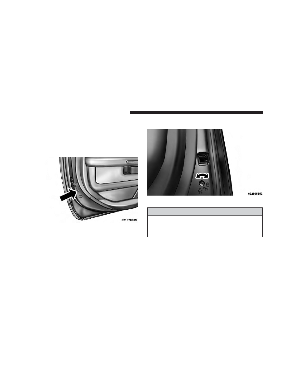
Modified Rear Door – Locks, Levers, And Window
Switches — If Equipped
To provide a safer environment for riding in the rear seat,
the rear doors of your vehicle have the Protection Door
Lock system.
To use the system, open each rear door, use a flat blade
screwdriver (or emergency key) and rotate the dial to
engage and disengage the Protection locks. When the
system on a door is engaged, that door can only be opened
by using the outside door handle even if the inside door
lock is in the unlocked position.
WARNING!
Avoid trapping anyone in a vehicle in a collision.
Remember that the rear doors can only be opened from
the outside when the Protection locks are engaged.
Protection Door Lock Location
Lock Control
6
THINGS TO KNOW BEFORE STARTING YOUR VEHICLE
OCCUPANT RESTRAINTS
Driver and Passenger Advanced Front Air Bags, Supple-
mental Side Curtain Air Bags (SABIC), and Seat-Mounted
Side Air Bags (SAB) affect the way special service equip-
ment can be safely mounted in special service vehicles.
Any surface that could come into contact with an air bag,
once it has been deployed, must not damage the air bag or
alter its deployment path.
The addition of the supplemental equipment (such as
radios, weapons, mounting brackets, cage, etc.), must be
installed such that it will not interfere or come in contact
with a deploying air bag. Air bag deployment zones are
described below. Sharp edges, corners or protrusions on
supplemental equipment, could damage the nylon air bag
material and reduce the effectiveness of the air bag during
a deployment.
WARNING!
• Vehicles equipped with left and right Supplemental
Side Curtain Air Bags (SABIC) must use police cages,
which have been approved by the equipment manu-
facturer, for use in the vehicle.
(Continued)
WARNING! (Continued)
• The area where the Supplemental Side Curtain Air
Bags (SABIC) is located should remain free from any
obstructions.
• If your vehicle is equipped with left and right
Supplemental Side Curtain Air Bags (SABIC), care
must be taken when installing any type of roof
equipment. Drilling and installation of fasteners or
other equipment that may interfere with the Supple-
mental Side Curtain Air Bags (SABIC) and air bag
wiring harness is not permitted. Furthermore, make
sure no equipment or fasteners are located in the air
bag deployment zone.
• Do not place objects or mount equipment in front of
the air bag module cover, or in front of the seat areas
that may come in contact with a deploying air bag.
• Dash, tunnel or console mounted equipment should
not be placed outside of the specified zone.
• Failure to follow these instructions could result in
personal injury.
2
THINGS TO KNOW BEFORE STARTING YOUR VEHICLE
7
Air Bag Deployment Zones
There are four zones to be aware of:
1. Driver Air Bag Deployment Zone (Figure 1), and Driver
Air Bag/Steering Wheel Specifications (Figure 2)
2. Passenger Air Bag Deployment Zone (Figure 3) and
(Figure 4)
3. Supplemental Side Air Bag Inflatable Curtain (SABIC)
Deployment Zone (Figure 5)
4. Supplemental Seat-Mounted Side Air Bag (SAB) De-
ployment Zone (Figure 6)
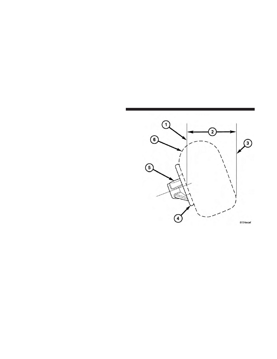
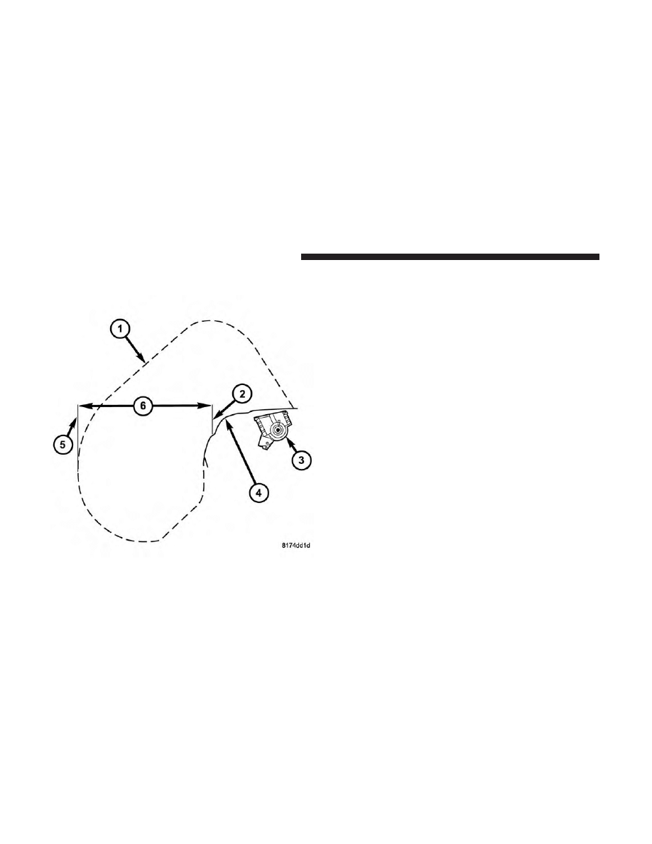
Figure 1 - Driver Air Bag Deployment Zone, depicts the
following.
Figure 1
8
THINGS TO KNOW BEFORE STARTING YOUR VEHICLE
1. Vertical Plane Passing Through Center of Steering
Wheel
2. 13 inches (330 mm)
3. Vertical Plane Passing Through Maximum Rearward
Point that the Driver Air Bag Cushion Reaches
4. Steering Wheel
5. Driver Air Bag Retainer/Housing
6. Driver Air Bag Cushion
DRIVER AIR BAG/STEERING COLUMN SPECIFICA-
TIONS
DRIVER AIR BAG CUSHION POSITION
DAB Diameter When
Deployed (Full)
26 inches (661 mm)
DAB Depth When
Deployed (Full)
12 inches (305 mm)
Maximum Rearward
Displacement During
Deployment (Fill)
16 inches (407 mm)
STEERING COLUMN TILT POSITION RANGE
+/– 2 Degrees from Steering Column Tilt Pivot Point
22.9 Degrees from Vertical is the Nominal Position
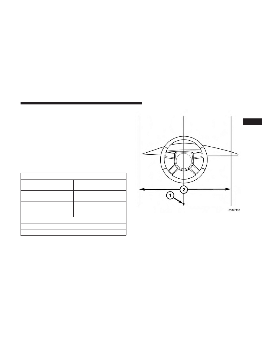
Figure 2 - Driver Air Bag Lateral Deployment Zone, depicts
the following.
1. Driver Seating Reference
Figure 2
2
THINGS TO KNOW BEFORE STARTING YOUR VEHICLE
9
2. Driver Air Bag Cushion Lateral Deployment Zone, 27
inches (686 mm).
Figure 3 - Passenger Air Bag Deployment Zone, depicts the
following.
1. Passenger Air Bag Cushion
2. Vertical Plane from Point of Instrument Panel
3. Passenger Air Bag Module
4. Instrument Panel
5. Vertical Plane Passing Through the Maximum Rearward
Point that the Passenger Air Bag Cushion Reaches
6. 23 inches (584 mm)
Figure 3
10
THINGS TO KNOW BEFORE STARTING YOUR VEHICLE
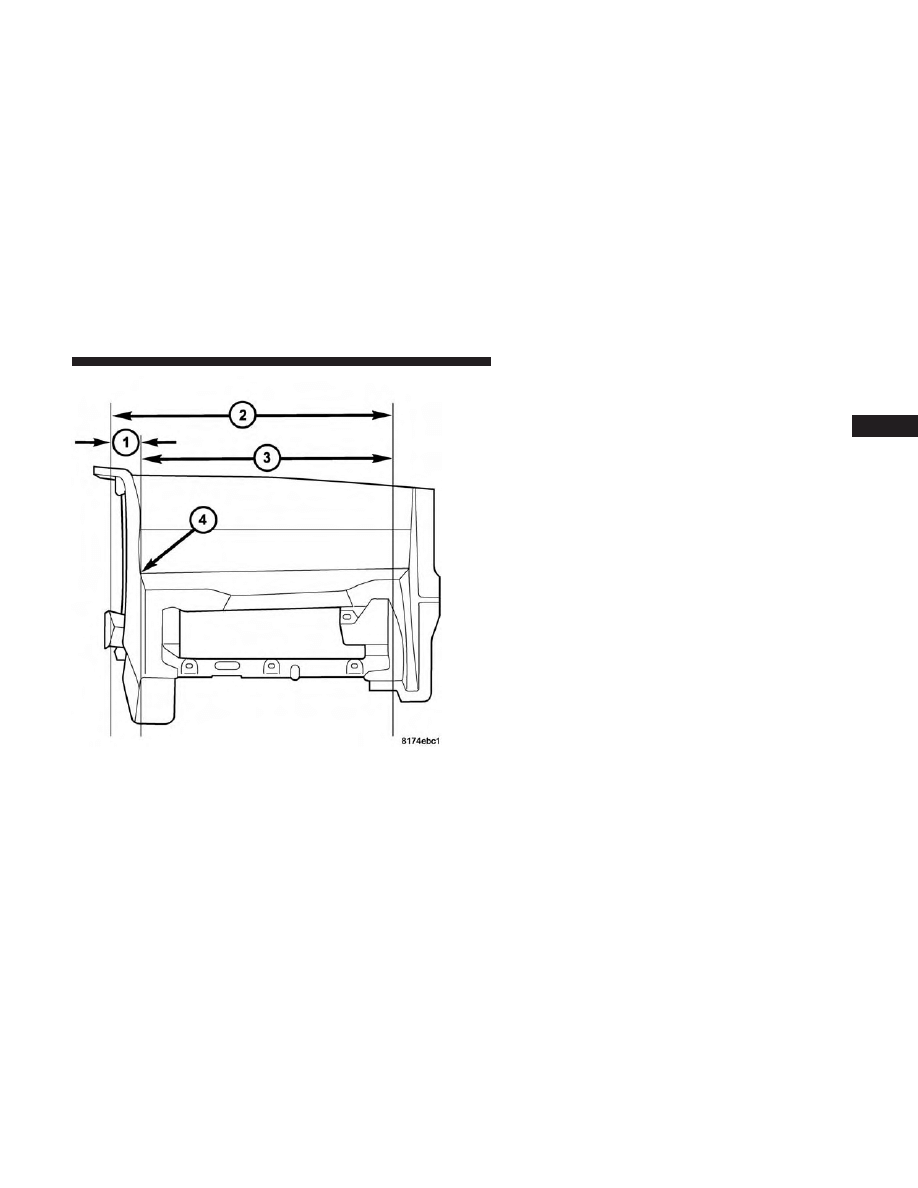
Figure 4 - Passenger Air Bag Lateral Deployment Zone,
depicts the following.
1. 4.70 inches (119 mm)
2. Passenger Air Bag Cushion Deployment Zone
3. 29.8 inches (756 mm)
4. Reference Point
Figure 4
2
THINGS TO KNOW BEFORE STARTING YOUR VEHICLE
11
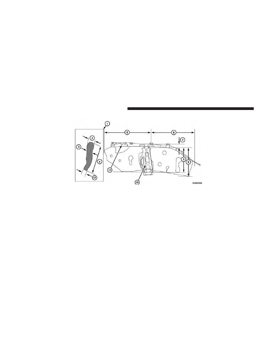
Figure 5 - Crew Cab Supplemental Side Air Bag Inflatable
Curtain Air Bag Deployment Zone, depicts the following.
1. Cross-Sectional Area Side View
2. 4.85 inches (123 mm)
3. 4.29 inches (109 mm)
4. 19.92 inches (506 mm)
5. 36.81 inches (935 mm)
6. 34.5 inches (877 mm)
7. 3.3 inches (84 mm)
8. 16.92 inches (430 mm)
9. 22.2 inches (566 mm)
10. B-Pillar Trim
11. Side-Curtain Air Bag Inflator Module
12. 2.83 inches (72 mm)
Figure 5
12
THINGS TO KNOW BEFORE STARTING YOUR VEHICLE
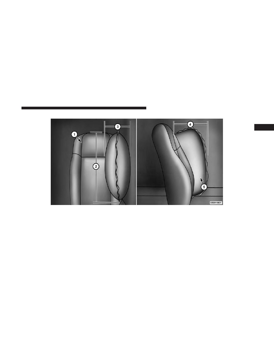
Figure 6 - Supplemental Seat Mounted Side Air Bag
Deployment Zone, depicts the following.
1. Front Driver’s Seat
2. 18.5 inches (470 mm)
3. 6.3 inches (160 mm)
4. 11.8 inches (300 mm)
5. Seat-Mounted Air Bag
Figure 6
2
THINGS TO KNOW BEFORE STARTING YOUR VEHICLE
13


UNDERSTANDING THE FEATURES OF YOUR VEHICLE
CONTENTS
䡵 LIGHTS . . . . . . . . . . . . . . . . . . . . . . . . . . . . . . .16
▫ Dome Light . . . . . . . . . . . . . . . . . . . . . . . . . . .16
3

LIGHTS
Dome Light
The special service dome light has three positions. Position
one is used for white light, and position two is used for red
LED light. Always remember to return the dome light
switch to the OFF (center) position when finished using to
prevent discharging the vehicle battery.
NOTE:
If your vehicle is equipped with illuminated ap-
proach lights under the outside mirrors they can be turned
off through the Instrument Cluster Display or the Uconnect
radio. For further information refer to “Instrument Cluster
Display” and “Uconnect Settings” in “Understanding Your
Instrument Panel” in your owners manual on the DVD.
Dome Light
16
UNDERSTANDING THE FEATURES OF YOUR VEHICLE

UNDERSTANDING YOUR INSTRUMENT PANEL
CONTENTS
䡵 INSTRUMENT CLUSTER DISPLAY . . . . . . . . . . . .18
▫ Vehicle Info (Customer Information Features) . . . .20
4
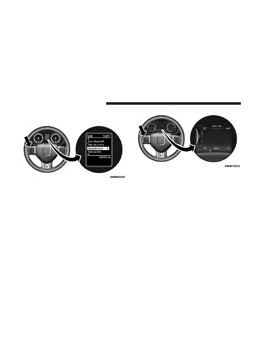
INSTRUMENT CLUSTER DISPLAY
The Instrument Cluster Display features a driver-
interactive display that is located in the instrument cluster.
Instrument Cluster Display — Base
Instrument Cluster Display — Premium
18
UNDERSTANDING YOUR INSTRUMENT PANEL
This system allows the driver to select a variety of useful
information by pushing the switches mounted on the
steering wheel. The Instrument Cluster Display may con-
sist of the following:
• Digital Speedometer
• Vehicle Info
• Fuel Economy Info
• Trip A
• Trip B
• Stop/Start Info (If Equipped)
• Trailer Tow
• Audio
• Stored Messages
• Screen Setup
• Vehicle Settings (Not Equipped with a Uconnect 5.0 &
8.4 radio)
• Settings
• Turn Menu Off
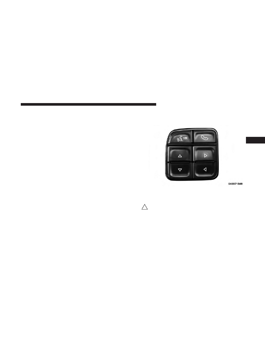
The system allows the driver to select information by
pushing the following buttons mounted on the steering
wheel:
• UP Arrow Button
Push and release the UP arrow button to scroll
upward through the main menu and submenus
(Fuel Economy, Trip A, Trip B, Audio, Stored
Messages, Screen Set Up).
Steering Wheel Buttons
4
UNDERSTANDING YOUR INSTRUMENT PANEL
19
• DOWN Arrow Button
Push and release the DOWN arrow button to
scroll downward through the main menu and
submenus (Fuel Economy, Trip A, Trip B, Audio,
Stored Messages, Screen Set Up).
• RIGHT Arrow Button
Push and release the RIGHT arrow button to
access/select the information screens or sub-
menu screens of a main menu item. Push and
hold the RIGHT arrow button for two seconds to
reset displayed/selected features that can be reset.
• LEFT Arrow Button
Push the LEFT arrow button to access/select the
information screens or submenu screens of a
main menu item or to return to the main menu
from an info screen or submenu item.
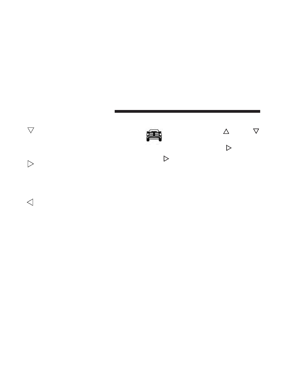
Vehicle Info (Customer Information Features)
Push and release the UP
or DOWN
arrow button until the Vehicle Info icon is
highlighted in the Instrument Cluster Display.
Push and release the RIGHT
arrow button
and Coolant Temp will be displayed. Push the
RIGHT
arrow button to scroll to the Engine Hour
information submenu:
Engine Hours
The Engine Hours submenu will display the following:
• Idle Hours
• Drive Hours
20
UNDERSTANDING YOUR INSTRUMENT PANEL


MAINTENANCE PROCEDURES
Special Service vehicles are equipped with heavy-duty
parts that are designed specifically for the varying de-
mands and unique requirements under which they are
operated. This booklet illustrates and describes the opera-
tion of unique features and equipment that are either
standard or optional on this vehicle. A description of
features and equipment no longer available, or not ordered
on this vehicle, may also be included. Please disregard any
features and equipment described in this manual that is not
on this vehicle.
Failure to maintain your vehicle properly may reduce
vehicle performance and operational capabilities, ad-
versely affect the safety of you and your passengers, as
well as restrict your warranty coverage. Refer to the
“Maintenance Schedule,” in the Owner’s Manual, for the
proper maintenance intervals.
The manufacturer reserves the right to make changes in
design and specifications, and/or make additions to or
improvements to its products, without imposing any obli-
gation upon itself to install them on products previously
manufactured.
22
MAINTAINING YOUR VEHICLE

INDEX
6

Door Locks . . . . . . . . . . . . . . . . . . . . . . . . . . . . . . . .6
Introduction . . . . . . . . . . . . . . . . . . . . . . . . . . . . . . . .4
Lights . . . . . . . . . . . . . . . . . . . . . . . . . . . . . . . . . . .16
Dome . . . . . . . . . . . . . . . . . . . . . . . . . . . . . . . . .16
Maintenance Procedures . . . . . . . . . . . . . . . . . . . . . .22
Occupant Restraints . . . . . . . . . . . . . . . . . . . . . . . . . .7
24
INDEX

INSTALLATION OF RADIO TRANSMITTING
EQUIPMENT
Special design considerations are incorporated into this
vehicle’s electronic system to provide immunity to radio
frequency signals. Mobile two-way radios and telephone
equipment must be installed properly by trained person-
nel. The following must be observed during installation.
The positive power connection should be made directly
to the battery and fused as close to the battery as possible.
The negative power connection should be made to body
sheet metal adjacent to the negative battery connection.
This connection should not be fused.
Antennas for two-way radios should be mounted on the
roof or the rear area of the vehicle. Care should be used
in mounting antennas with magnet bases. Magnets may
affect the accuracy or operation of the compass on
vehicles so equipped.
The antenna cable should be as short as practical and
routed away from the vehicle wiring when possible. Use
only fully shielded coaxial cable.
Carefully match the antenna and cable to the radio to
ensure a low Standing Wave Ratio (SWR).
Mobile radio equipment with output power greater than
normal may require special precautions.
All installations should be checked for possible interfer-
ence between the communications equipment and the
vehicle’s electronic systems.

2017 RAM TRUCK 1500
First Edition
Printed in U.S.A.
©2016 FCA US LLC. All Rights Reserved.
Ram is a registered trademark of FCA US LLC.
17D243-226-AA
S P E C I A L S E R V I C E S U P P L E M E N T
2 0 1 7
R A M T R U C K 1 5 0 0
STICK WITH THE SPECIALISTS
®
2404656 Ram Truck 1500 Special Suppl OM.indd 1
5/2/16 5:59 PM
Document Outline
- INTRODUCTION
- THINGS TO KNOW BEFORE STARTING YOUR VEHICLE
- UNDERSTANDING THE FEATURES OF YOUR VEHICLE
- UNDERSTANDING YOUR INSTRUMENT PANEL
- MAINTAINING YOUR VEHICLE
- INDEX
Wyszukiwarka
Podobne podstrony:
2017 RAM CNG sup
akumulator do lada nova 2105 2108 2109 1500 s 1500 special 15
RAM 1500, Heavy Duty 2500 3500 2014 US
CV Specialiste dans le Service de Marketing wzór
Prezentacja firmy MARSTATE SERVICE BHP PPOZ PPT
hplj 5p 6p service manual vhnlwmi5rxab6ao6bivsrdhllvztpnnomgxi2ma vhnlwmi5rxab6ao6bivsrdhllvztpnnomg
PAT DS 350 Graphic Modular GM Service Data
Oberheim Prommer Service Manual
Funai Hita9801 Service Note
03 Service Specifications
Korg SQ 10 Service Manual
OIL SERVICE
MAC1500 service manual
A10VO Series 31 Size 28 Service Parts list
Hitachi Vm Series Camcorder Servicing
MEDC17 Special Function Manual
Jak mieć wolną pamięć RAM, A TO POTRZEBNE
więcej podobnych podstron