
O W N E R ’ S M A N U A L
S U P P L E M E N T
2 0 1 7
R A M T R U C K 2 5 0 0
C O M P R E S S E D N A T U R A L G A S

VEHICLES SOLD IN CANADA
With respect to any Vehicles Sold in Canada, the name FCA
US LLC shall be deemed to be deleted and the name FCA
Canada Inc. used in substitution therefore.
DRIVING AND ALCOHOL
Drunken driving is one of the most frequent causes of
accidents.
Your driving ability can be seriously impaired with blood
alcohol levels far below the legal minimum. If you are
drinking, don’t drive. Ride with a designated non-
drinking driver, call a cab, a friend, or use public trans-
portation.
WARNING!
Driving after drinking can lead to an accident.
Your perceptions are less sharp, your reflexes are
slower, and your judgment is impaired when you
have been drinking. Never drink and then drive.
This manual illustrates and describes the operation of
features and equipment that are either standard or op-
tional on this vehicle. This manual may also include a
description of features and equipment that are no longer
available or were not ordered on this vehicle. Please
disregard any features and equipment described in this
manual that are not on this vehicle.
FCA US LLC reserves the right to make changes in design
and specifications, and/or make additions to or improve-
ments to its products without imposing any obligation
upon itself to install them on products previously manu-
factured.
Copyright © 2016 FCA US LLC

TABLE OF CONTENTS
SECTION
PAGE
1
2
3
4
5
6
7
1
2
3
4
5
6
7


INTRODUCTION
This booklet is a supplement to the Ram 1500/2500/3500
Owner’s Manual. It contains information relative to the
Compressed Natural Gas equipment installed on this ve-
hicle by the manufacturer. You are urged to read this
publication and the Owner’s Manual carefully.
Following the instructions and recommendations provided
herein will help assure safe and reliable operation of your
vehicle. After you have read the booklet it should be stored
in the vehicle for convenient reference and remain with the
vehicle when sold.
When it comes to service, remember that your authorized
dealer knows your vehicle best, has factory-trained techni-
cians and genuine MOPAR® parts, and cares about your
satisfaction.
4
INTRODUCTION

THINGS TO KNOW BEFORE STARTING YOUR VEHICLE
CONTENTS
䡵 GENERAL INFORMATION . . . . . . . . . . . . . . . . . .6
䡵 SAFETY WARNINGS . . . . . . . . . . . . . . . . . . . . . . .6
䡵 MANUAL SHUT OFF VALVE . . . . . . . . . . . . . . . . .8
2

GENERAL INFORMATION
Your vehicle is designed to operate on gasoline or Com-
pressed Natural Gas (CNG). Compressed Natural Gas is
made up primarily of methane and is in a gaseous state at
all times.
The manufacturer’s built vehicles equipped with com-
pressed natural gas fueled engines are identified by the
character T in the eighth (engine) position of the Vehicle
Identification Number (V.I.N.).
SAFETY WARNINGS
Natural gas is safe and reliable, when used properly. For
safe operation of your vehicle, observe the following
precautions:
WARNING!
• Your vehicle fuel system has a maximum capacity of
3,600 pounds per square inch gauge (24.8 MPa)
compensated to a temperature of 70° F (21° C). The
vehicle should only be filled from refueling equip-
ment incorporating temperature compensation to
70° F (21° C). Exceeding the fuel system capacity may
result in fuel system damage and possibly cause
injury.
• Do not attempt to force open or tamper with the fuel
fill receptacle. A sudden release of natural gas may
occur, possibly causing injury.
• Natural gas contains an odorant additive and persis-
tent natural gas odor may indicate a leak. If a
persistent natural odor is detected, the cause should
be located and corrected immediately by a qualified
technician.
(Continued)
6
THINGS TO KNOW BEFORE STARTING YOUR VEHICLE
WARNING! (Continued)
• Do not park or service your vehicle near any source
of excessive heat or open flame. Never use a paint
oven to cure any paint repairs. The natural gas
storage containers on this vehicle are equipped with
pressure relief devices which vent at 230° F (110° C).
• Do not paint or under coat any natural gas fuel
system components. Unlike gasoline, a compressed
natural gas fuel system is under very high pressure
even when the engine is not running. To avoid risk of
personal injury, any repair to the fuel system should
be performed by a qualified technician.
• Natural gas vapors at atmospheric pressure are
lighter than air and will rise and disperse in open
areas. In enclosed areas, natural gas vapor may
collect and form a combustible mixture. If the vehicle
is routinely placed in an enclosed area, the area
should be provided with adequate ventilation and/or
a natural gas detection system. For long term storage,
the manual shutoff valve and individual container
valves should be closed.
(Continued)
WARNING! (Continued)
• When a vehicle is involved in an accident which has
or may have caused damage to the natural gas fuel
system, the system must be inspected and pressure
tested by a qualified technician before returning the
vehicle to service.
• Any fuel system component, including the contain-
ers, that has been subjected to fire may not be
returned to service due to reduced pressure capabil-
ity.
2
THINGS TO KNOW BEFORE STARTING YOUR VEHICLE
7
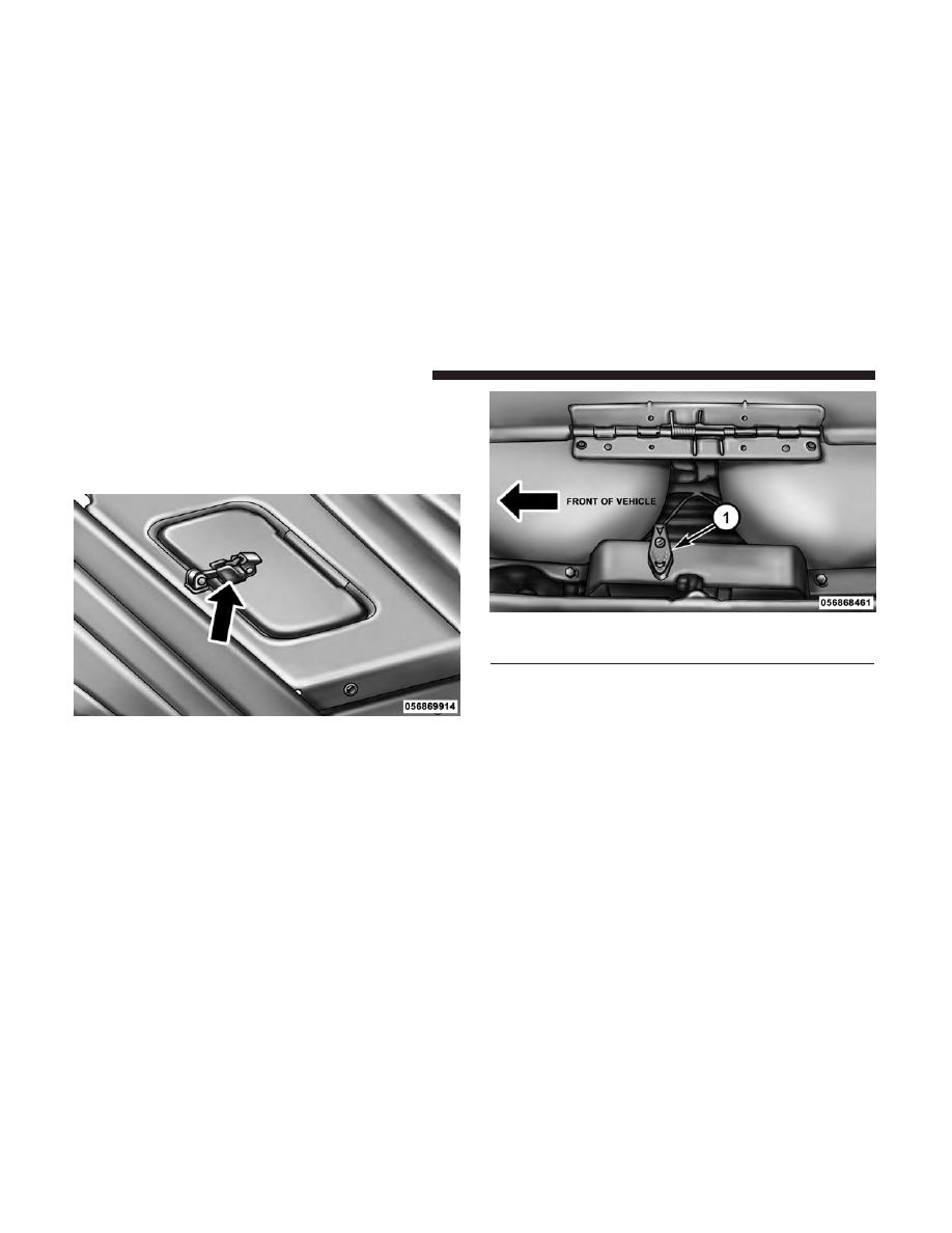
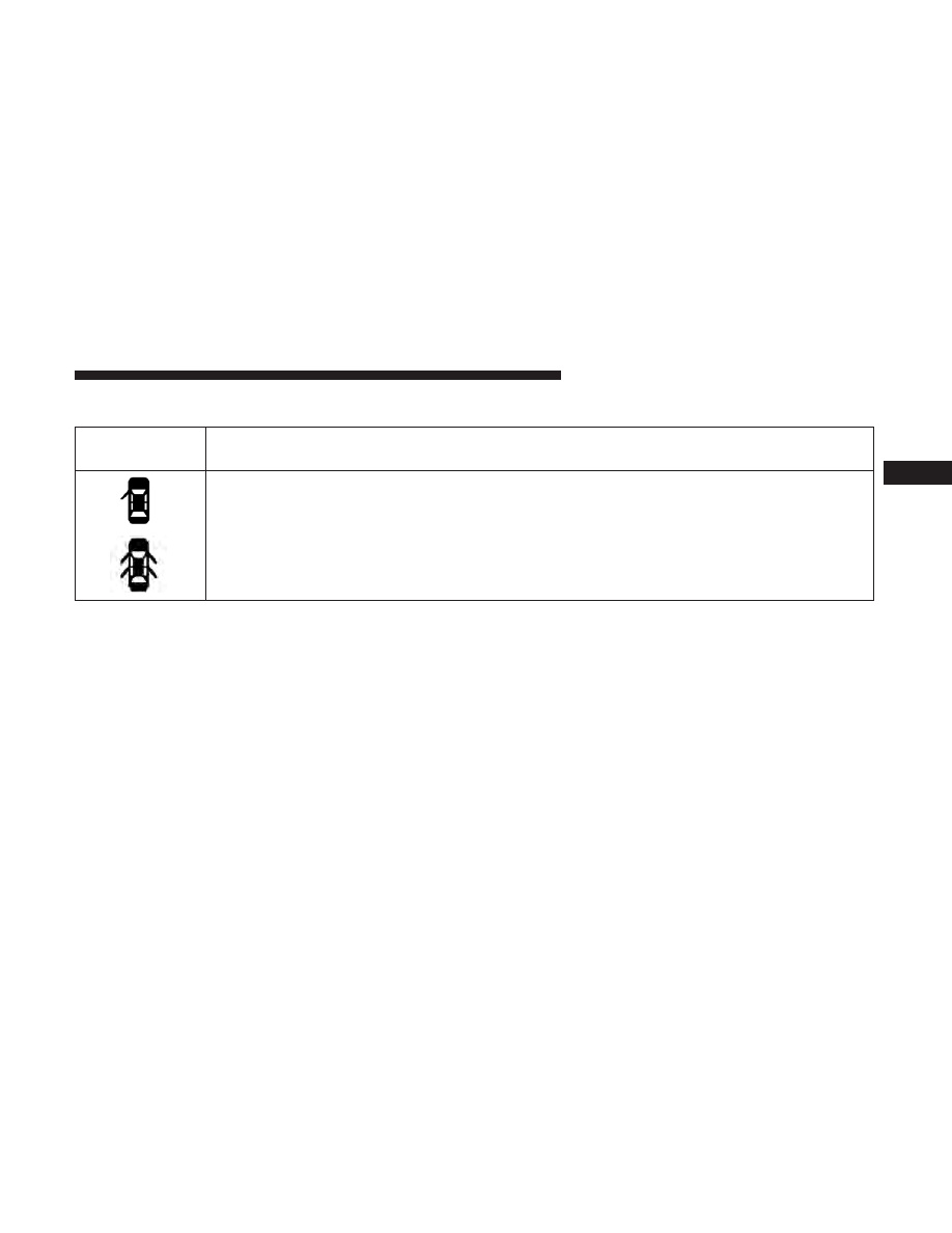
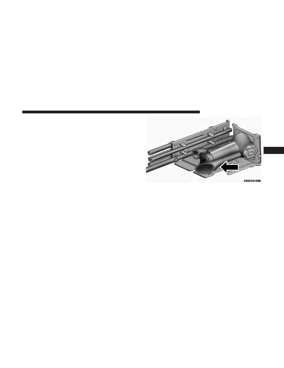
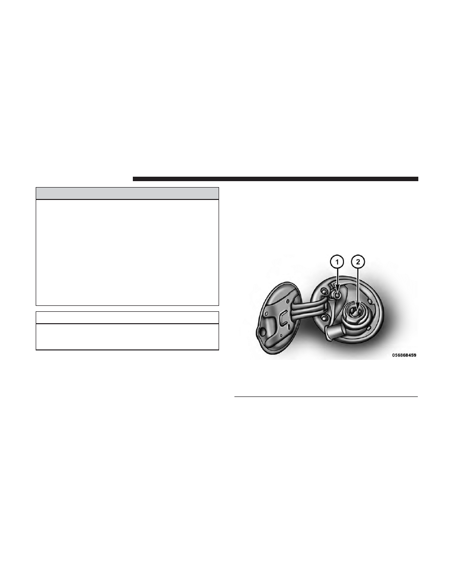
MANUAL SHUT OFF VALVE
The manual one-quarter turn shut off valve is located
inside the protective cover for the tanks. It’s location is
identified by a label on the top of the cover. This valve
isolates the fuel containers from the rest of the fuel system.
1 — Valve Off
Manual Shut Off Valve Access Door
Manual Shut Off Valve
8
THINGS TO KNOW BEFORE STARTING YOUR VEHICLE
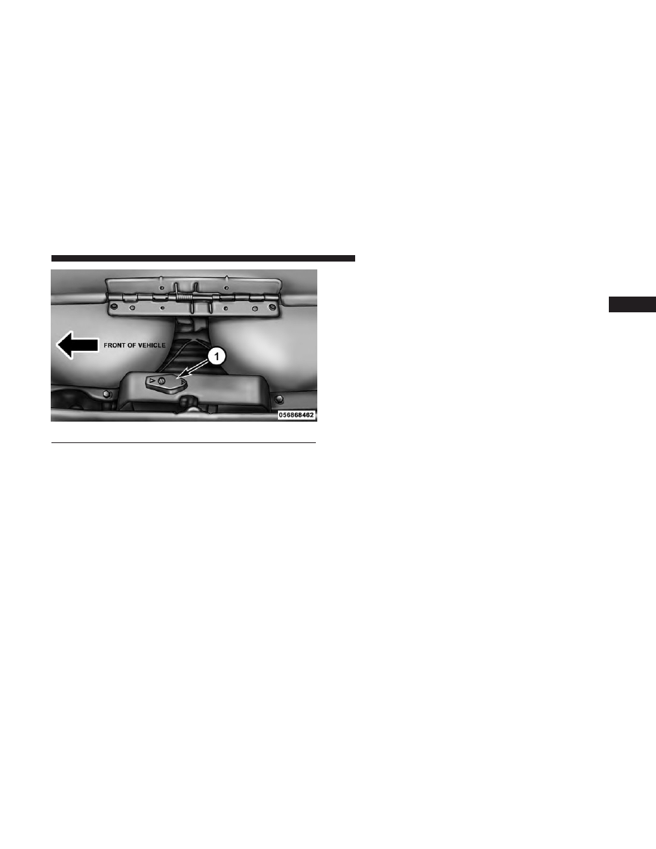
1 — Valve On
2
THINGS TO KNOW BEFORE STARTING YOUR VEHICLE
9


UNDERSTANDING YOUR INSTRUMENT PANEL
CONTENTS
䡵 INSTRUMENT CLUSTER . . . . . . . . . . . . . . . . . . .12
䡵 WARNING AND INDICATOR LIGHTS . . . . . . . . .16
▫ Red Telltale Indicator Lights . . . . . . . . . . . . . . . .17
▫ Yellow Telltale Indicator Lights . . . . . . . . . . . . . .24
▫ Green Telltale Indicator Lights . . . . . . . . . . . . . .38
▫ White Telltale Indicator Lights . . . . . . . . . . . . . .40
▫ Blue Telltale Indicator Lights. . . . . . . . . . . . . . . .42
䡵 INSTRUMENT CLUSTER DISPLAY . . . . . . . . . . . .42
▫ Instrument Cluster Display Controls . . . . . . . . . .43
▫ Instrument Cluster Display Screens . . . . . . . . . . .45
▫ Oil Life Reset . . . . . . . . . . . . . . . . . . . . . . . . . .47
▫ Instrument Cluster Display Selectable Menu
Items . . . . . . . . . . . . . . . . . . . . . . . . . . . . . . . .48
▫ Instrument Cluster Display Messages . . . . . . . . .54
▫ Instrument Cluster Display Controls . . . . . . . . . .57
3
INSTRUMENT CLUSTER
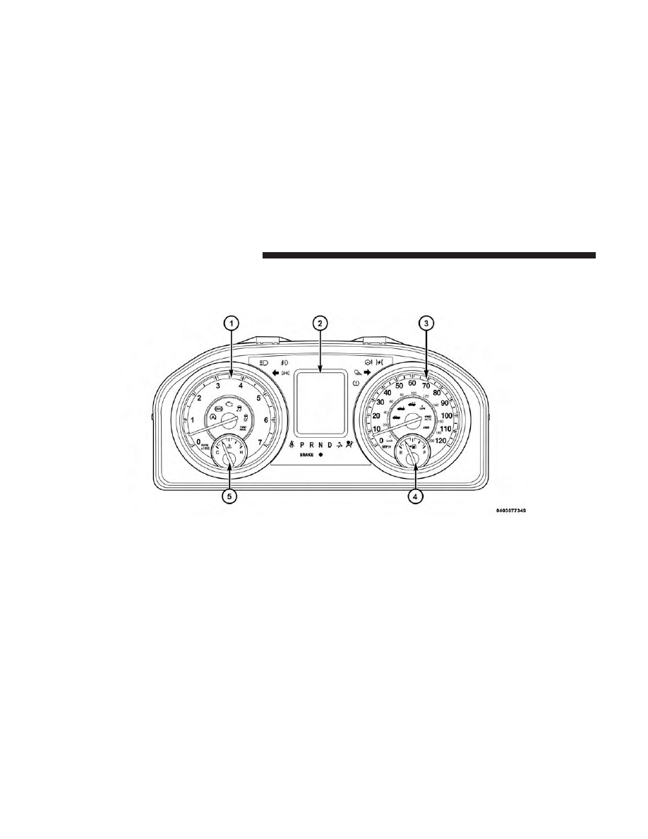
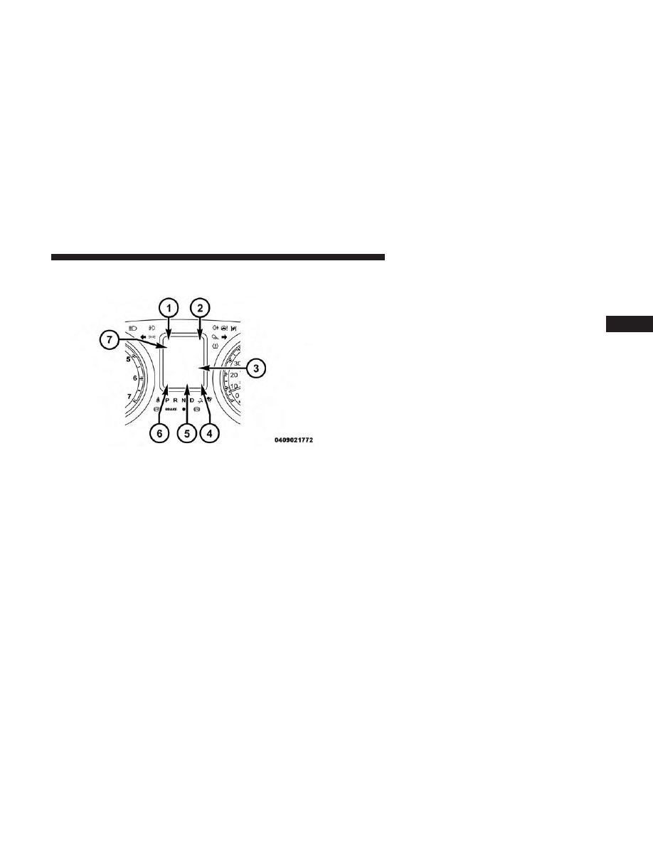
Base Instrument Clusters
12
UNDERSTANDING YOUR INSTRUMENT PANEL
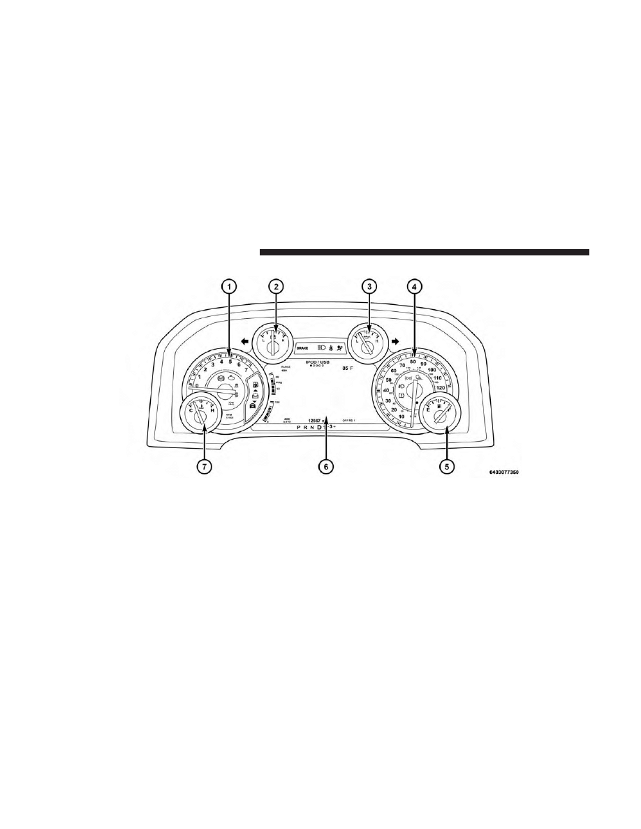
1. Tachometer
• Indicates the engine speed in revolutions per minute
(RPM x 1000).
2. Instrument Cluster Display
• When the appropriate conditions exist, this display
shows the Instrument Cluster Display messages. Refer
to “Instrument Cluster Display” in “Understanding
Your Instrument Panel” for further information.
3. Speedometer
• Indicates vehicle speed.
4. Fuel Gauge
• The pointer shows the level of fuel in the fuel tank
when the ignition is in the ON/RUN position.
•
The fuel pump symbol points to the side of the
vehicle where the fuel door is located.
5. Temperature Gauge
• The temperature gauge shows engine coolant tem-
perature. Any reading within the normal range indi-
cates that the engine cooling system is operating
satisfactorily.
• The gauge pointer will likely indicate a higher tem-
perature when driving in hot weather, up mountain
grades, or when towing a trailer. It should not be
allowed to exceed the upper limits of the normal
operating range.
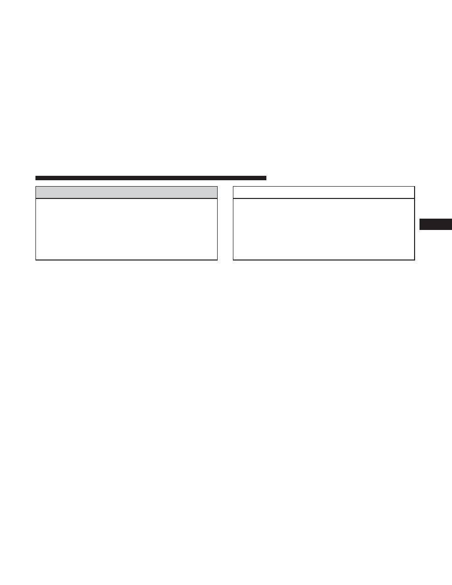
WARNING!
A hot engine cooling system is dangerous. You or
others could be badly burned by steam or boiling
coolant. You may want to call an authorized dealer for
service if your vehicle overheats. If you decide to look
under the hood yourself, see “Maintaining Your Ve-
hicle”. Follow the warnings under the Cooling System
Pressure Cap paragraph.
CAUTION!
Driving with a hot engine cooling system could dam-
age your vehicle. If the temperature gauge reads “H”
pull over and stop the vehicle. Idle the vehicle with the
air conditioner turned off until the pointer drops back
into the normal range. If the pointer remains on the
“H”, turn the engine off immediately and call an
authorized dealer for service.
3
UNDERSTANDING YOUR INSTRUMENT PANEL
13
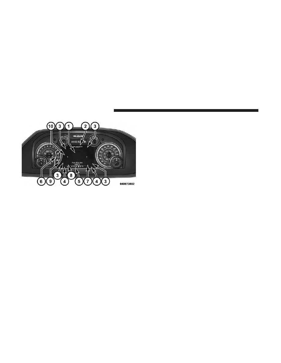
Premium Instrument Clusters
14
UNDERSTANDING YOUR INSTRUMENT PANEL

1. Tachometer
• Indicates the engine speed in revolutions per minute
(RPM x 1000).
2. Voltmeter
• When the engine is running, the gauge indicates the
electrical system voltage. The pointer should stay
within the normal range if the battery is charged. If the
pointer moves to either extreme left or right and
remains there during normal driving, the electrical
system should be serviced.
NOTE:
The voltmeter may show a gauge fluctuation at
various engine temperatures. This cycling operation is
caused by the post-heat cycle of the intake manifold heater
system. The number of cycles and the length of the cycling
operation is controlled by the engine control module.
Post-heat operation can run for several minutes, and then
the electrical system and voltmeter needle will stabilize.
3. Oil Pressure Gauge
• The pointer should always indicate some oil pressure
when the engine is running. A continuous high or low
reading under normal driving conditions may indicate
a lubrication system malfunction. Immediate service
should be obtained from an authorized dealer.
4. Speedometer
• Indicates vehicle speed.
5. Fuel Gauge
• The pointer shows the level of fuel in the fuel tank
when the ignition is in the ON/RUN position.
•
The fuel pump symbol points to the side of the
vehicle where the fuel door is located.
6. Instrument Cluster Display
• When the appropriate conditions exist, this display
shows the Instrument Cluster Display messages. Refer
to “Instrument Cluster Display” in “Understanding
Your Instrument Panel” for further information.
7. Temperature Gauge
• The temperature gauge shows engine coolant tem-
perature. Any reading within the normal range indi-
cates that the engine cooling system is operating
satisfactorily.
• The gauge pointer will likely indicate a higher tem-
perature when driving in hot weather, up mountain
grades, or when towing a trailer. It should not be
allowed to exceed the upper limits of the normal
operating range.
3
UNDERSTANDING YOUR INSTRUMENT PANEL
15

WARNING!
A hot engine cooling system is dangerous. You or
others could be badly burned by steam or boiling
coolant. You may want to call an authorized dealer for
service if your vehicle overheats. If you decide to look
under the hood yourself, see “Maintaining Your Ve-
hicle”. Follow the warnings under the Cooling System
Pressure Cap paragraph.
CAUTION!
Driving with a hot engine cooling system could dam-
age your vehicle. If the temperature gauge reads “H”
pull over and stop the vehicle. Idle the vehicle with the
air conditioner turned off until the pointer drops back
into the normal range. If the pointer remains on the
“H”, turn the engine off immediately and call an
authorized dealer for service.
WARNING AND INDICATOR LIGHTS
IMPORTANT:
The warning / indicator lights switch on in
the instrument panel together with a dedicated message
and/or acoustic signal when applicable. These indications
are indicative and precautionary and as such must not be
considered as exhaustive and/or alternative to the infor-
mation contained in the Owner’s Manual, which you are
advised to read carefully in all cases. Always refer to the
information in this chapter in the event of a failure indica-
tion.
All active telltales will display first if applicable. The
system check menu may appear different based upon
equipment options and current vehicle status. Some tell-
tales are optional and may not appear.
16
UNDERSTANDING YOUR INSTRUMENT PANEL
Red Telltale Indicator Lights
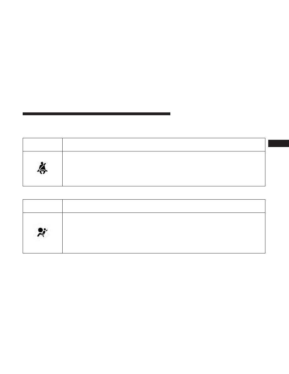
Seat Belt Reminder Warning Light
Red Telltale
Light
What It Means
Seat Belt Reminder Warning Light
When the ignition is first placed in the ON/RUN position, if the driver’s seat belt is unbuckled, a
chime will sound and the light will turn on. When driving, if the driver or front passenger seat
belt remains unbuckled, the Seat Belt Reminder Light will flash or remain on continuously and a
chime will sound. Refer to “Occupant Restraints” in “Things To Know Before Starting Your Ve-
hicle” for further information.
Air Bag Warning Light
Red Telltale
Light
What It Means
Air Bag Warning Light
This light will turn on for four to eight seconds as a bulb check when the ignition is placed in the
ON/RUN position. If the light is either not on during startup, stays on, or turns on while driv-
ing, have the system inspected at an authorized dealer as soon as possible. This light will illumi-
nate with a single chime when a fault with the Air Bag Warning Light has been detected, it will
stay on until the fault is cleared. If the light comes on intermittently or remains on while driving,
have an authorized dealer service the vehicle immediately.
3
UNDERSTANDING YOUR INSTRUMENT PANEL
17
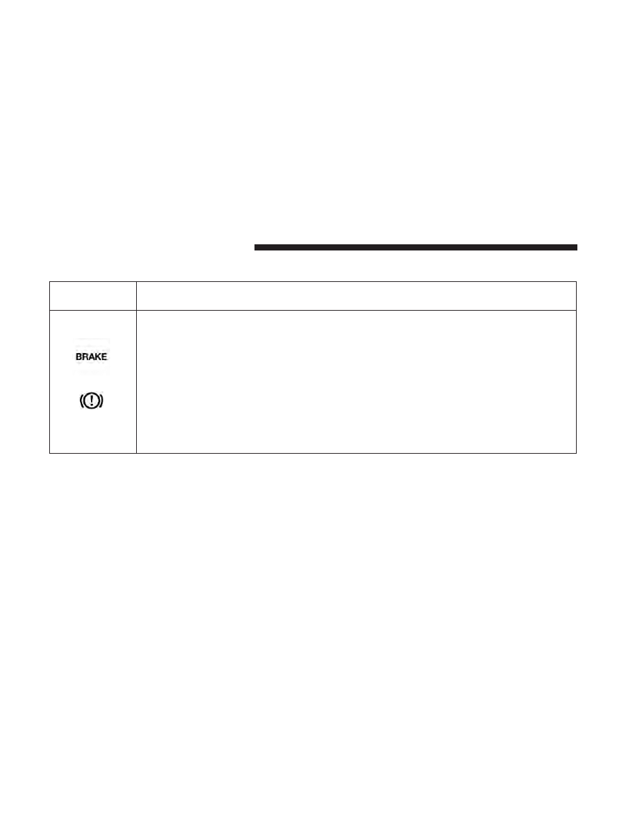
Brake Warning Light
Red Telltale
Light
What It Means
United States
Canada
Brake Warning Light
This light monitors various brake functions, including brake fluid level and parking brake appli-
cation. If the brake light turns on it may indicate that the parking brake is applied, that the brake
fluid level is low, or that there is a problem with the anti-lock brake system reservoir.
If the light remains on when the parking brake has been disengaged, and the fluid level is at the
full mark on the master cylinder reservoir, it indicates a possible brake hydraulic system mal-
function or that a problem with the Brake Booster has been detected by the Anti-Lock Brake Sys-
tem (ABS) / Electronic Stability Control (ESC) system. In this case, the light will remain on until
the condition has been corrected. If the problem is related to the Brake Booster, the ABS pump
will run when applying the brake, and a brake pedal pulsation may be felt during each stop.
NOTE:
Brake Warning Light may illuminate due to excessive wear to brake pads.
The dual brake system provides a reserve braking capacity
in the event of a failure to a portion of the hydraulic
system. A leak in either half of the dual brake system is
indicated by the Brake Warning Light, which will turn on
when the brake fluid level in the master cylinder has
dropped below a specified level.
The light will remain on until the cause is corrected.
NOTE:
The light may flash momentarily during sharp
cornering maneuvers, which change fluid level conditions.
The vehicle should have service performed, and the brake
fluid level checked.
If brake failure is indicated, immediate repair is necessary.
18
UNDERSTANDING YOUR INSTRUMENT PANEL
WARNING!
Driving a vehicle with the red brake light on is
dangerous. Part of the brake system may have failed. It
will take longer to stop the vehicle. You could have a
collision. Have the vehicle checked immediately.
Vehicles equipped with the Anti-Lock Brake System (ABS)
are also equipped with Electronic Brake Force Distribution
(EBD). In the event of an EBD failure, the Brake Warning
Light will turn on along with the ABS Light. Immediate
repair to the ABS system is required.
Operation of the Brake Warning Light can be checked by
placing the ignition in the ON/RUN position. The light
should illuminate for approximately two seconds. The light
should then turn off unless the parking brake is applied or
a brake fault is detected. If the light does not illuminate,
have the light inspected by an authorized dealer.
The light also will turn on when the parking brake is
applied with the ignition placed in the ON/RUN position.
NOTE:
This light shows only that the parking brake is
applied. It does not show the degree of brake application.
Vehicle Security Warning Light — If Equipped
Red Telltale
Light
What It Means
Vehicle Security Warning Light — If Equipped
This light will flash at a fast rate for approximately 15 seconds when the vehicle security alarm is
arming, and then will flash slowly until the vehicle is disarmed.
3
UNDERSTANDING YOUR INSTRUMENT PANEL
19
Engine Temperature Warning Light
Red Warning
Light
What It Means
Engine Temperature Warning Light
This light warns of an overheated engine condition. As engine coolant temperatures rise and the
gauge approaches H, this indicator will illuminate and a single chime will sound after reaching a
set threshold. Further overheating will cause a continuous chime sound for 4 minutes, or until
the engine is allowed to cool, whichever comes first.
If the light turns on while driving, safely pull over and stop the vehicle. If the A/C system is on,
turn it off. Also, shift the transmission into NEUTRAL and idle the vehicle. If the temperature
reading does not return to normal, turn the engine off immediately and call for service. Refer to
“If Your Engine Overheats” in “What To Do In Emergencies” for further information.
Battery Charge Warning Light
Red Telltale
Light
What It Means
Battery Charge Warning Light
This light illuminates when the battery is not charging properly. If it stays on while the engine is
running, there may be a malfunction with the charging system. Contact your authorized dealer as
soon as possible. This indicates a possible problem with the electrical system or a related compo-
nent.
20
UNDERSTANDING YOUR INSTRUMENT PANEL
Oil Pressure Warning Light
Red Telltale
Light
What It Means
Oil Pressure Warning Light
This light indicates low engine oil pressure. If the light turns on while driving, stop the vehicle
and shut off the engine as soon as possible. A chime will sound when this light turns on.
Do not operate the vehicle until the cause is corrected. This light does not indicate how much oil
is in the engine. The engine oil level must be checked under the hood.
Electronic Throttle Control (ETC) Warning Light
Red Telltale
Light
What It Means
Electronic Throttle Control (ETC) Warning Light
This light informs you of a problem with the Electronic Throttle Control (ETC) system. If a prob-
lem is detected while the engine is running, the light will either stay on or flash depending on
the nature of the problem. Cycle the ignition key when the vehicle is safely and completely
stopped and the transmission is placed in the PARK position. The light should turn off. If the
light remains on with the engine running, your vehicle will usually be drivable; however, see an
authorized dealer for service as soon as possible.
If the light continues to flash when the engine is running, immediate service is required and you
may experience reduced performance, an elevated/rough idle, or engine stall and your vehicle
may require towing. The light will come on when the ignition is first turned to ON/RUN and
remain on briefly as a bulb check. If the light does not come on during starting, have the system
checked by an authorized dealer.
3
UNDERSTANDING YOUR INSTRUMENT PANEL
21
Electric Power Steering Fail Warning Light — If
Equipped
Red Telltale
Light
What It Means
Electric Power Steering Fail Warning — If Equipped
This light is used to manage the electrical warning of the EPS (Electric Power Steering). Refer to
“Power Steering” in “Starting And Operating” for further information.
Trailer Brake Disconnected Warning Light
Red Warning
Light
What It Means
Trailer Brake Disconnected Warning Light
This telltale is on when the Trailer Brake has been disconnected.
22
UNDERSTANDING YOUR INSTRUMENT PANEL
Door Open Warning Light
Red Telltale
Light
What It Means
Door Open Warning Light
This indicator will illuminate when a door is open and not fully closed.
NOTE:
If the vehicle is moving there will also be a single chime.
NOTE:
Door Open Warning Light will differ depending on
the equipped Instrument Cluster Display.
3
UNDERSTANDING YOUR INSTRUMENT PANEL
23

Yellow Telltale Indicator Lights
Engine Check/Malfunction Indicator Light (MIL)
Yellow Telltale
Light
What It Means
Engine Check/Malfunction Indicator Light (MIL)
The Engine Check/Malfunction Indicator Light (MIL) is a part of an Onboard Diagnostic System
called OBD II that monitors engine and automatic transmission control systems. The light will
illuminate when the ignition is in the ON/RUN position before engine start. If the bulb does not
come on when turning the key from OFF to ON/RUN, have the condition checked promptly.
Certain conditions, such as a loose or missing gas cap, poor quality fuel, etc., may illuminate the
light after engine start. The vehicle should be serviced if the light stays on through several typical
driving styles. In most situations, the vehicle will drive normally and will not require towing.
When the engine is running, the MIL may flash to alert serious conditions that could lead to im-
mediate loss of power or severe catalytic converter damage. The vehicle should be serviced as
soon as possible if this occurs.
24
UNDERSTANDING YOUR INSTRUMENT PANEL
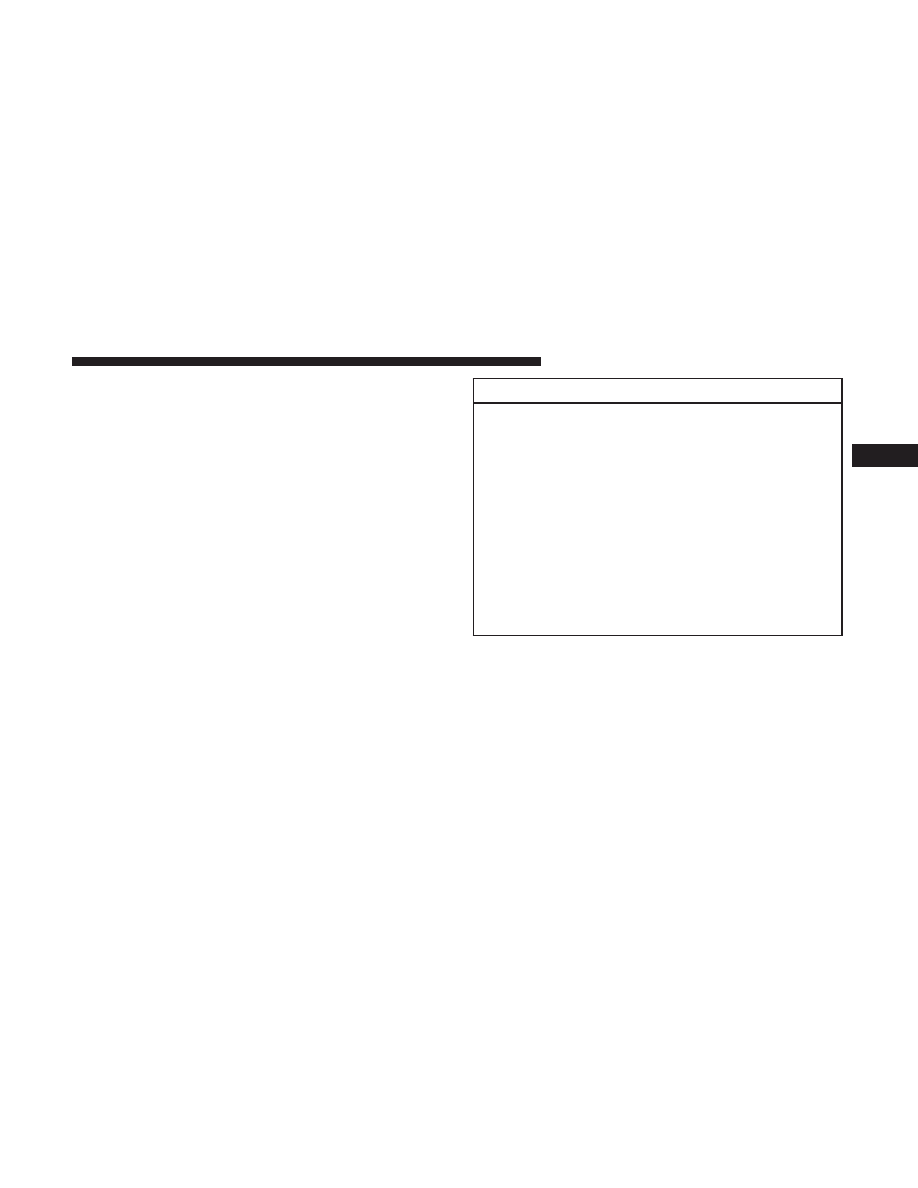
WARNING!
A malfunctioning catalytic converter, as referenced
above, can reach higher temperatures than in normal
operating conditions. This can cause a fire if you drive
slowly or park over flammable substances such as dry
plants, wood, cardboard, etc. This could result in death
or serious injury to the driver, occupants or others.
CAUTION!
Prolonged driving with the Malfunction Indicator
Light (MIL) on could cause damage to the engine
control system. It also could affect fuel economy and
driveability. If the MIL is flashing, severe catalytic
converter damage and power loss will soon occur.
Immediate service is required.
3
UNDERSTANDING YOUR INSTRUMENT PANEL
25

Electronic Stability Control (ESC) Indicator Light —
If Equipped
Yellow Telltale
Light
What It Means
Electronic Stability Control (ESC) Indicator Light — If Equipped
The “ESC Indicator Light” in the instrument cluster will come on when the ignition is placed in
the ON/RUN position, and when ESC is activated. It should go out with the engine running. If
the “ESC Indicator Light” comes on continuously with the engine running, a malfunction has
been detected in the ESC system. If this light remains on after several ignition cycles, and the ve-
hicle has been driven several miles (kilometers) at speeds greater than 30 MPH (48 km/h), see
your authorized dealer as soon as possible to have the problem diagnosed and corrected.
• The “ESC Off Indicator Light” and the “ESC Indicator Light” come on momentarily each
time the ignition is placed in the ON/RUN position.
• Each time the ignition is turned to ON/RUN, the ESC system will be ON, even if it was
turned off previously.
• The ESC system will make buzzing or clicking sounds when it is active. This is normal; the
sounds will stop when ESC becomes inactive.
• This light will come on when the vehicle is in an ESC event.
26
UNDERSTANDING YOUR INSTRUMENT PANEL
Electronic Stability Control (ESC) OFF Indicator
Light — If Equipped
Yellow Telltale
Light
What It Means
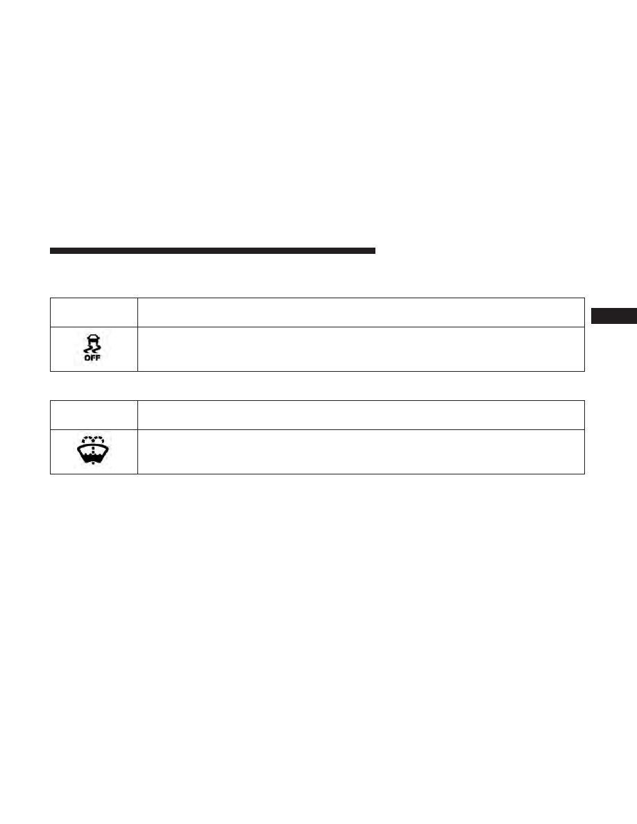
Electronic Stability Control (ESC) OFF Indicator Light — If Equipped
This light indicates the Electronic Stability Control (ESC) is off.
Low Washer Fluid Indicator Light — If Equipped
Yellow Telltale
Light
What It Means
Low Washer Fluid Indicator Light — If Equipped
This indicator will illuminate when the windshield washer fluid is low.
3
UNDERSTANDING YOUR INSTRUMENT PANEL
27

Tire Pressure Monitoring Indicator Light
Yellow Telltale
Light
What It Means
Tire Pressure Monitoring Indicator Light
The warning light switches on and a message is displayed to indicate that the tire pressure is
lower than the recommended value and/or that slow pressure loss is occurring. In these cases,
optimal tire duration and fuel consumption may not be guaranteed.
Should one or more tires be in the condition mentioned above, the display will show the indica-
tions corresponding to each tire in sequence.
IMPORTANT:
Do not continue driving with one or more
flat tires as handling may be compromised. Stop the
vehicle, avoiding sharp braking and steering. Repair im-
mediately using the dedicated tire repair kit and contact
your authorized dealership as soon as possible.
Each tire, including the spare (if provided), should be
checked monthly when cold and inflated to the inflation
pressure recommended by the vehicle manufacturer on the
vehicle placard or tire inflation pressure label. If your
vehicle has tires of a different size than the size indicated
on the vehicle placard or tire inflation pressure label, you
should determine the proper tire inflation pressure for
those tires.
As an added safety feature, your vehicle has been
equipped with a Tire Pressure Monitoring System (TPMS)
that illuminates a low tire pressure telltale when one or
more of your tires is significantly under-inflated. Accord-
ingly, when the low tire pressure telltale illuminates, you
should stop and check your tires as soon as possible and
inflate them to the proper pressure. Driving on a signifi-
cantly under-inflated tire causes the tire to overheat and
can lead to tire failure. Under-inflation also reduces fuel
efficiency and tire tread life, and may affect the vehicle’s
handling and stopping ability.
28
UNDERSTANDING YOUR INSTRUMENT PANEL
Please note that the TPMS is not a substitute for proper tire
maintenance, and it is the driver’s responsibility to main-
tain correct tire pressure, even if under-inflation has not
reached the level to trigger illumination of the TPMS low
tire pressure telltale.
Your vehicle has also been equipped with a TPMS
malfunction indicator to indicate when the system is not
operating properly. The TPMS malfunction indicator is
combined with the low tire pressure telltale. When the
system detects a malfunction, the telltale will flash for
approximately one minute and then remain continu-
ously illuminated. This sequence will continue upon
subsequent vehicle start-ups as long as the malfunction
exists. When the malfunction indicator is illuminated,
the system may not be able to detect or signal low tire
pressure as intended. TPMS malfunctions may occur for
a variety of reasons, including the installation of re-
placement or alternate tires or wheels on the vehicle that
prevent the TPMS from functioning properly. Always
check the TPMS malfunction telltale after replacing one
or more tires or wheels on your vehicle, to ensure that
the replacement or alternate tires and wheels allow the
TPMS to continue to function properly.
CAUTION!
The TPMS has been optimized for the original equip-
ment tires and wheels. TPMS pressures and warning
have been established for the tire size equipped on
your vehicle. Undesirable system operation or sensor
damage may result when using replacement equip-
ment that is not of the same size, type, and/or style.
Aftermarket wheels can cause sensor damage. Using
aftermarket tire sealants may cause the Tire Pressure
Monitoring System (TPMS) sensor to become inoper-
able. After using an aftermarket tire sealant it is
recommended that you take your vehicle to an autho-
rized dealership to have your sensor function checked.
3
UNDERSTANDING YOUR INSTRUMENT PANEL
29

Low Fuel Indicator Light
Yellow Telltale
Light
What It Means
Low Fuel Indicator Light
When the fuel level reaches approximately 3.0 gal (11.0 L) this light will turn on, and remain on
until fuel is added.
Anti-Lock Brake (ABS) Indicator Light
Yellow Telltale
Light
What It Means
Anti-Lock Brake (ABS) Indicator Light
After the ignition is turned on, the Anti-Lock Brake System (ABS) light illuminates to indicate
function check at vehicle startup. If the light remains on after startup or comes on and stays on at
road speeds, it may indicate that the ABS has detected a malfunction or has become inoperative.
The system reverts to standard non-anti-lock brakes.
If both the Brake Warning Light and the ABS Warning Light are on, see an authorized dealer im-
mediately. Refer to “Anti-Lock Brake System” in “Starting And Operating” for further informa-
tion.
30
UNDERSTANDING YOUR INSTRUMENT PANEL
Transmission Temperature Indicator Light
Yellow Telltale
Light
What It Means
Transmission Temperature Indicator Light
This light indicates that the transmission fluid temperature is running hot. This may occur with
severe usage, such as trailer towing. If this light turns on, safely pull over and stop the vehicle.
Then, shift the transmission into NEUTRAL and run the engine at idle or faster until the light
turns off.
WARNING!
If you continue operating the vehicle when the Trans-
mission Temperature Warning Light is illuminated you
could cause the fluid to boil over, come in contact with
hot engine or exhaust components and cause a fire.
CAUTION!
Continuous driving with the Transmission Tempera-
ture Warning Light illuminated will eventually cause
severe transmission damage or transmission failure.
3
UNDERSTANDING YOUR INSTRUMENT PANEL
31
Rear Fog Light Indicator — If Equipped
Yellow Telltale
Light
What It Means
Rear Fog Light Indicator
This indicator will illuminate when the rear fog lights are on.
Low Coolant Level Indicator Light
Yellow Telltale
Light
What It Means
Low Coolant Level Indicator Light
This telltale will turn on to indicate the vehicle coolant level is low.
Air Suspension Payload Protection Telltale — If Equipped
Yellow Telltale
Light
What It Means
Air Suspension Payload Protection Telltale
This telltale will turn on to indicate that the maximum payload may have been exceeded or load
leveling cannot be achieved at its current ride height. Protection Mode will automatically be se-
lected in order to “protect” the air suspension system, air suspension adjustment is limited due to
payload.
32
UNDERSTANDING YOUR INSTRUMENT PANEL
TOW/HAUL Indicator Light
Yellow Telltale
Light
What It Means
TOW/HAUL Indicator Light
This light will illuminate when TOW HAUL mode is selected.
Cargo Light — If Equipped
Yellow Tell-
tale Light
What It Means
Cargo Light
The cargo light will illuminate when the cargo light is activated by pushing the cargo light button on
the headlight switch.
Loose Fuel Filler Cap Indicator Light — If Equipped
Yellow Telltale
Light
What It Means
Loose Fuel Filler Cap Indicator Light — If Equipped
This light will illuminate when the fuel filler cap is loose. Properly close the filler cap to disen-
gage the light. If the light does not turn off, please see your authorized dealer.
3
UNDERSTANDING YOUR INSTRUMENT PANEL
33
Air Suspension Off-Road 1 Indicator Light — If
Equipped
Yellow Telltale
Light
What It Means
Air Suspension Off-Road 1 Indicator Light
This light will illuminate when the air suspension system is set to the Off-Road 1 setting. For fur-
ther information, refer to “Air Suspension System” in “Starting And Operating”.
Air Suspension Off-Road 2 Indicator Light — If
Equipped
Yellow Telltale
Light
What It Means
Air Suspension Off-Road 2 Indicator Light
This light will illuminate when the air suspension system is set to the Off-Road 2 setting. For fur-
ther information, refer to “Air Suspension System” in “Starting And Operating”.
34
UNDERSTANDING YOUR INSTRUMENT PANEL
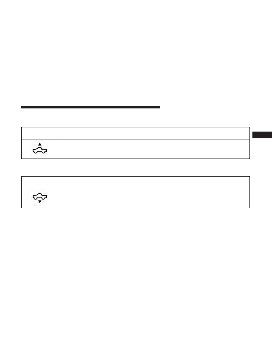
Air Suspension Ride Height Raising Indicator
Light— If Equipped
Yellow Telltale
Light
What It Means
Air Suspension Ride Height Raising Indicator Light
This light will blink and alert the driver that the vehicle is changing to a higher ride height.
Air Suspension Ride Height Lowering Indicator
Light— If Equipped
Yellow Telltale
Light
What It Means
Air Suspension Ride Height Lowering Indicator Light
This light will blink and alert the driver that the vehicle is changing to a lower ride height.
3
UNDERSTANDING YOUR INSTRUMENT PANEL
35

4WD Indicator Light — If Equipped
Yellow Telltale
Light
What It Means
4WD Indicator Light
This light alerts the driver that the vehicle is in the four-wheel drive mode, and the front and
rear driveshafts are mechanically locked together forcing the front and rear wheels to rotate at
the same speed.
4WD Lock Indicator Light — If Equipped
Yellow Telltale
Light
What It Means
4WD Lock Indicator Light
This light alerts the driver that the vehicle is locked in the four-wheel drive mode, and the front
and rear driveshafts are mechanically locked together forcing the front and rear wheels to rotate
at the same speed.
NEUTRAL Indicator Light — If Equipped
Yellow Telltale
Light
What It Means
NEUTRAL Indicator Light
This light alerts the driver that the vehicle is in the NEUTRAL mode and the front and rear
driveshafts are disengaged from the powertrain.
36
UNDERSTANDING YOUR INSTRUMENT PANEL

4 Low Indicator Light — If Equipped
Yellow Telltale
Light
What It Means
4 Low Indicator Light
This light alerts the driver that the vehicle is in the four-wheel drive LOW mode. The front and
rear driveshafts are mechanically locked together forcing the front and rear wheels to rotate at
the same speed. Low range provides a greater gear reduction ratio to provide increased torque at
the wheels.
Refer to “Four-Wheel Drive Operation — If Equipped” in “Starting And Operating” for further
information on four-wheel drive operation and proper use.
Service 4WD Indicator Light — If Equipped
Yellow Telltale
Light
What It Means
Service 4WD Indicator Light
If the light stays on or comes on during driving, it means that the 4WD system is not functioning
properly and that service is required. We recommend you drive to the nearest service center and
have the vehicle serviced immediately.
3
UNDERSTANDING YOUR INSTRUMENT PANEL
37
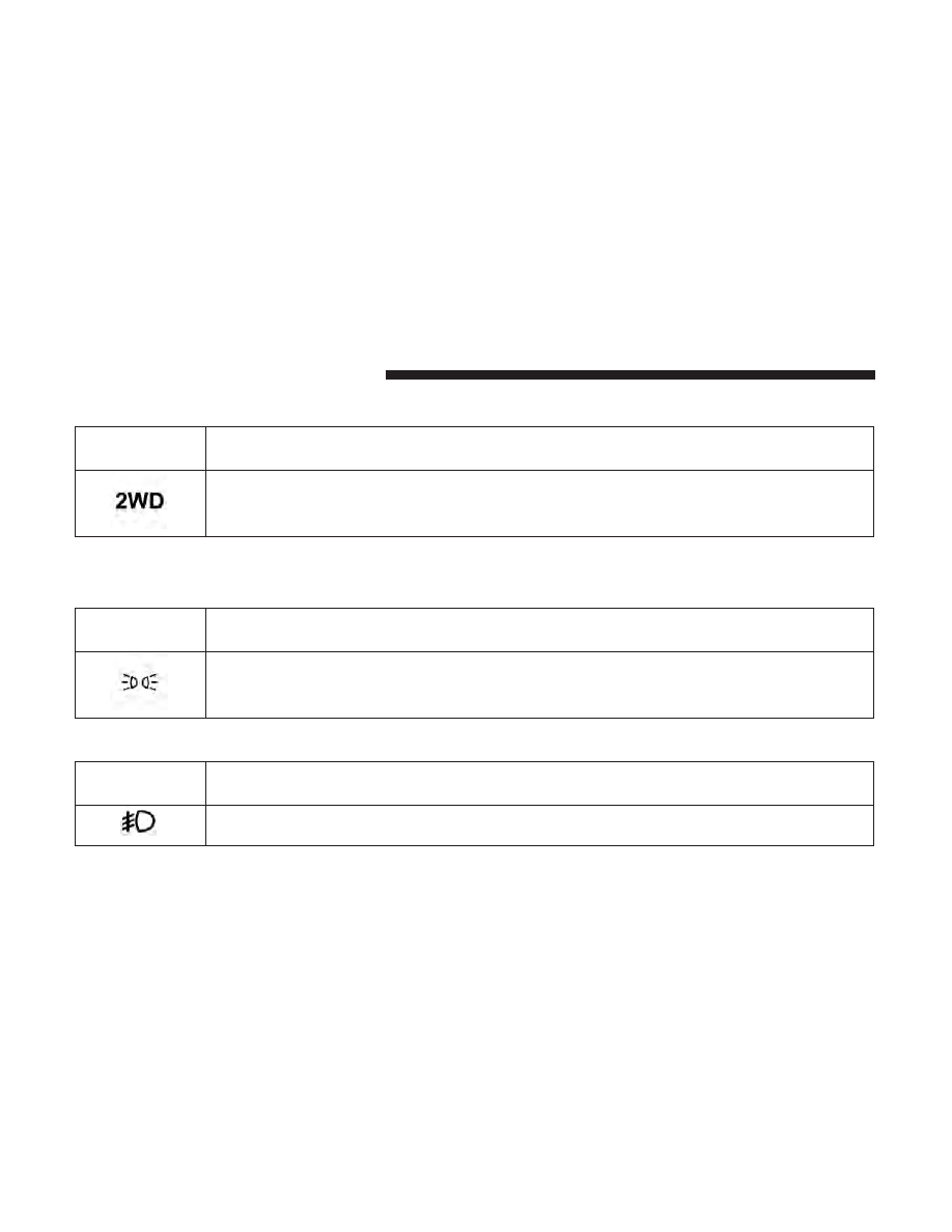
2WD Indicator Light — If Equipped
Yellow Telltale
Light
What It Means
2WD Indicator Light
This light alerts the driver that the vehicle is in the two-wheel drive mode.
Green Telltale Indicator Lights
Park/Headlight ON Indicator Light
Green Telltale
Light
What It Means
Park/Headlight ON Indicator Light
This indicator will illuminate when the park lights or headlights are turned on.
Front Fog Indicator Light — If Equipped
Green Telltale
Light
What It Means
Front Fog Indicator Light — If Equipped
This indicator will illuminate when the front fog lights are on.
38
UNDERSTANDING YOUR INSTRUMENT PANEL
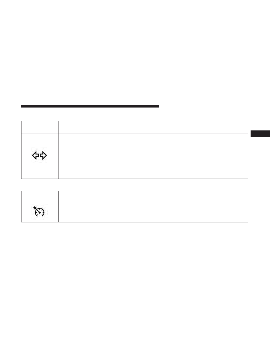
Turn Signal Indicator Lights
Green Telltale
Light
What It Means
Turn Signal Indicator Lights
The instrument cluster directional arrow will flash independently for the LEFT or RIGHT turn
signal as selected, as well as the exterior turn signal lamp(s) (front and rear) as selected when the
multifunction lever is moved down (LEFT) or up (RIGHT).
NOTE:
• A continuous chime will sound if the vehicle is driven more than 1 mile (1.6 km) with either
turn signal on.
• Check for an inoperative outside light bulb if either indicator flashes at a rapid rate.
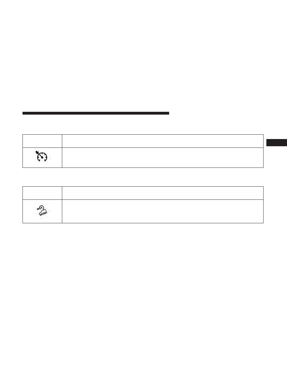
Cruise Control Set Indicator Light — If Equipped
Green Telltale
Light
What It Means
Cruise Control Set Indicator Light — If Equipped
This light will turn on when the electronic speed control has been set.
3
UNDERSTANDING YOUR INSTRUMENT PANEL
39
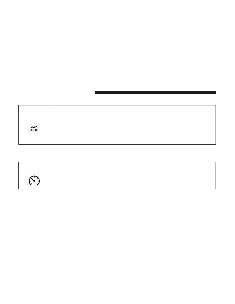
4WD AUTO Indicator Light — If Equipped
Green Telltale
Light
What It Means
4WD AUTO Indicator Light
This light alerts the driver that the vehicle is in the four-wheel drive auto mode, and the front
axle is engaged, but the vehicle’s power is sent to the rear wheels. Four-wheel drive will be auto-
matically engaged when the vehicle senses a loss of traction.
For further information on four-wheel drive operation and proper use, refer to “Four-Wheel
Drive Operation — If Equipped” in “Starting And Operating.”
White Telltale Indicator Lights
Cruise Control Ready Indicator Light
White Telltale
Light
What It Means
Cruise Control Ready Indicator Light
This light will turn on when the electronic speed control is ON, but not set.
40
UNDERSTANDING YOUR INSTRUMENT PANEL
Electronic Speed Control SET Indicator Light — If
Equipped
White Telltale
Light
What It Means
Electronic Speed Control SET Indicator Light
This light will turn on when the electronic speed control is set. Refer to “Electronic Speed Con-
trol” in “Understanding The Features Of Your Vehicle” for further information.
Hill Descent Control (HDC) Indicator Light — If
Equipped
White Telltale
Light
What It Means
Hill Descent Control (HDC) Indicator Light
This indicator will illuminate when Hill Descent Control (HDC) has been selected using the Hill
Descent Control Switch. Refer to “Electronic Brake Control” in “Starting And Operating” for fur-
ther information.
3
UNDERSTANDING YOUR INSTRUMENT PANEL
41
Blue Telltale Indicator Lights
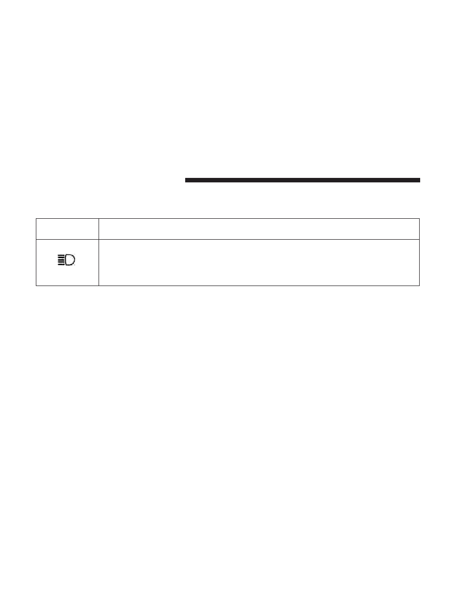
High Beam Indicator Light
Blue Telltale
Light
What It Means
High Beam Indicator Light
This indicator shows that the high beam headlights are on. Push the multifunction control lever
away from you to switch the headlights to high beam. Pull the lever toward you to switch the
headlights back to low beam. Pull the lever toward you for a temporary high beam on,
⬙flash to
pass
⬙ scenario.
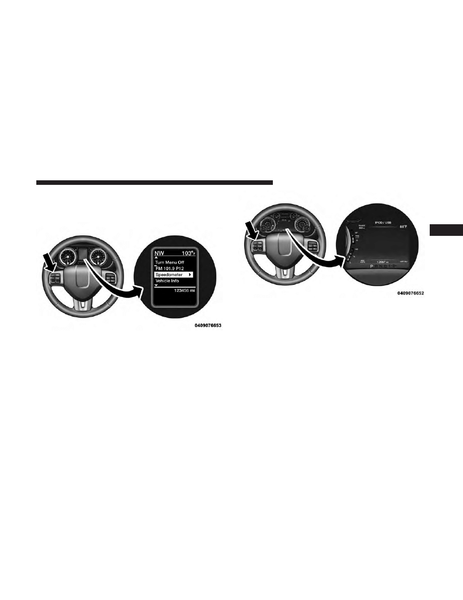
INSTRUMENT CLUSTER DISPLAY
Your vehicle may be equipped with an Instrument Cluster
Display, which offers useful information to the driver. With
the ignition in the STOP/OFF position (and the key
removed, for vehicles with mechanical key), opening/
closing of a door will activate the display for viewing, and
display the total miles or kilometers in the odometer. Your
Instrument Cluster Display is designed to display impor-
tant information about your vehicle’s systems and features.
Using a driver interactive display located on the instru-
ment panel, your Instrument Cluster Display can show you
how systems are working and give you warnings when
they aren’t. The steering wheel mounted controls allow
you to scroll through and enter the main menus and
submenus. You can access the specific information you
want and make selections and adjustments.
42
UNDERSTANDING YOUR INSTRUMENT PANEL
Instrument Cluster Display Controls
The Instrument Cluster Display features a driver-
interactive display that is located in the instrument cluster.
The Instrument Cluster Display Menu items may consist of
the following:
• Speedometer
• Vehicle Info
• Fuel Economy Info
• Trip A
• Trip B
• Stop/Start Info (If Equipped)
• Air Suspension (If Equipped)
Base Instrument Cluster Display
Premium Instrument Cluster Display
3
UNDERSTANDING YOUR INSTRUMENT PANEL
43
• Audio
• Trailer Tow
• Stored Messages
• Screen Setup
• Vehicle Settings (Not Equipped with a Uconnect 5.0 &
8.4 radio)
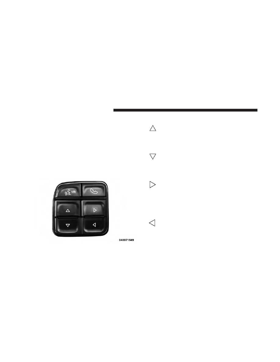
The system allows the driver to select information by
pushing the following Instrument Cluster Display Control
buttons located on the left side of the steering wheel:
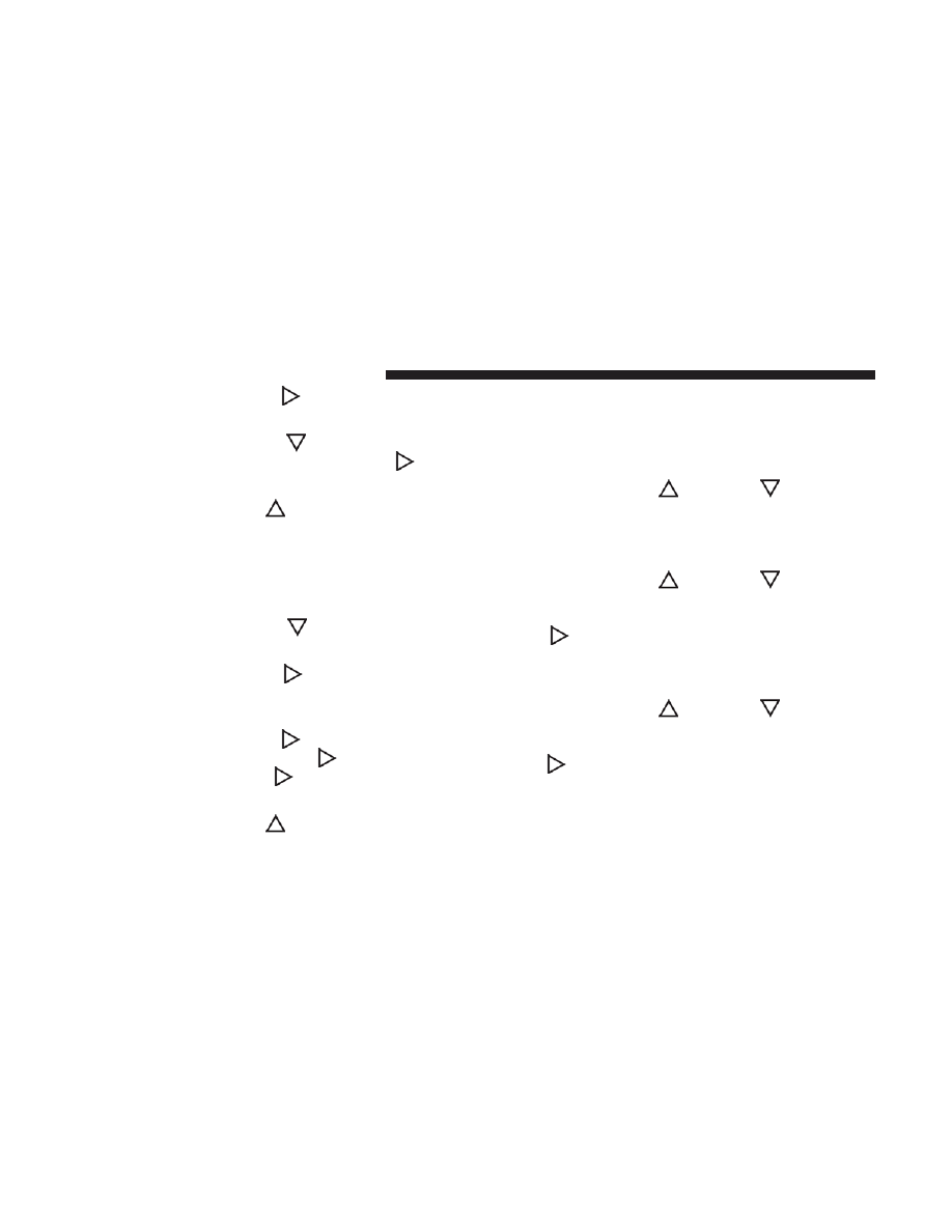
• UP Arrow Button
Push and release the UP arrow button to scroll
upward through the main menu items, submenu
screen, and vehicle settings.
• DOWN Arrow Button
Push and release the DOWN arrow button to
scroll downward through the main menu items,
submenu screen, and vehicle settings.
• RIGHT Arrow Button
Push and release the RIGHT arrow button to
access/select the information screens or sub-
menu screens of a main menu item. Push and
hold the RIGHT arrow button for two seconds to
reset displayed/selected features that can be reset.
• LEFT Arrow Button
Push and release the LEFT arrow button to
access/select the information screens, submenu
screens of a main menu item, or to return to the
main menu.
Instrument Cluster Display Control Buttons
44
UNDERSTANDING YOUR INSTRUMENT PANEL
Instrument Cluster Display Screens
The Instrument Cluster Display Screens are located in the
center portion of the cluster and consists of seven sections:
1. Compass Display
Displays the current direction. Refer to “Compass Settings”
under “Customer Programmable Features — Uconnect
5.0/8.4 Settings” for further information.
2. Temperature Display
Displays the temperature in degrees Celsius or degrees
Fahrenheit.
3. Main Screen
Displays main menu, submenus, settings.
4. White Telltales
5. Amber Telltales
6. Red Telltales
7. Audio/Phone Information And Submenu Information
Base Instrument Cluster Display
3
UNDERSTANDING YOUR INSTRUMENT PANEL
45
The Instrument Cluster Display Screens are located in the
center portion of the cluster and consists of eight sections:
1. Main Screen — The inner ring of the display will
illuminate in grey under normal conditions, yellow for
non critical warnings, red for critical warnings, and
white for on demand information.
2. Audio / Phone Information and Submenu Information
— Whenever there are sub-menus available, the position
within the submenus is shown here.
3. Selectable Information (Compass, Temp, Range to
Empty, Trip A, Trip B, Average MPG, Trailer Trip (dis-
tance only), Trailer Brake Gain, Time)
4. Telltales/Indicators
5. Gear Selector Status (PRNDL)
6. Selectable Menu Icons
7. Air Suspension Status – If Equipped
8. 4WD Status
9. Selectable Gauge 2 (Trans Temp, Oil Temp, Oil Life,
Trailer Brake, Current MPG)
10. Selectable Gauge 1 (Trans Temp, Oil Temp, Oil Life,
Trailer Brake, Current MPG)
The Instrument Cluster Display area will normally display
the main menu or the screens of a selected feature of the
main menu. The main display area also displays “pop up”
messages that consist of approximately 60 possible warn-
ing or information messages. These pop up messages fall
into several categories:
• Five Second Stored Messages
When the appropriate conditions occur, this type of mes-
sage takes control of the main display area for five seconds
Premium Instrument Cluster Display
46
UNDERSTANDING YOUR INSTRUMENT PANEL

and then returns to the previous screen. Most of the
messages of this type are then stored (as long as the
condition that activated it remains active) and can be
reviewed from the “Messages” main menu item. As long as
there is a stored message, an “i” will be displayed in the
Instrument Cluster Display’s compass/outside temp line.
Examples of this message type are “Right Front Turn Signal
Lamp Out” and “Low Tire Pressure.”
• Unstored Messages
This message type is displayed indefinitely or until the
condition that activated the message is cleared. Examples
of this message type are “Turn Signal On” (if a turn signal
is left on) and “Lights On” (if driver leaves the vehicle).
• Unstored Messages Until RUN
These messages deal primarily with the Remote Start
feature. This message type is displayed until the ignition is
in the RUN state. Examples of this message type are
“Remote Start Aborted - Door Ajar” and “Press Brake
Pedal and Push Button to Start.”
• Five Second Unstored Messages
When the appropriate conditions occur, this type of mes-
sage takes control of the main display area for five seconds
and then returns to the previous screen. An example of this
message type is “Automatic High Beams On.”
Oil Life Reset
Your vehicle is equipped with an engine oil change indi-
cator system. The “Oil Change Required” message will
display in the Instrument Cluster Display after a single
chime has sounded, to indicate the next scheduled oil
change interval. The engine oil change indicator system is
duty cycle based, which means the engine oil change
interval may fluctuate, dependent upon your personal
driving style.
NOTE:
Use the steering wheel Instrument Cluster Display
controls for the following procedure(s).
Vehicles Equipped With Passive Entry
1. Without pushing the brake pedal, push the ENGINE
START/STOP button and place the ignition to the
ON/RUN position (do not start the engine).
2. Push and release the DOWN
arrow button to scroll
downward through the main menu to “Vehicle Info.”
3. Push and release the RIGHT
arrow button to access
the ”Vehicle Info” screen, then scroll up or down to
select “Oil Life.”
3
UNDERSTANDING YOUR INSTRUMENT PANEL
47
4. Push and hold the RIGHT
arrow button to select
“Reset”.
5. Push and release the DOWN
arrow button to select
“Yes,” then push and release the RIGHT
arrow
button to select reset of the Oil Life to 100%.
6. Push and release the UP
arrow button to exit the
Instrument Cluster Display screen.
Vehicles Not Equipped With Passive Entry
1. Without pushing the brake pedal, cycle the ignition to
the ON/RUN position (do not start the engine).
2. Push and release the DOWN
arrow button to scroll
downward through the main menu to “Vehicle Info.”
3. Push and release the RIGHT
arrow button to access
the “Vehicle Info” screen then scroll up or down to
select “Oil Life.”
4. Push and hold the RIGHT
arrow button to select
“YES” by pushing the RIGHT
arrow then push
and release the RIGHT
arrow button to select
reset of the Oil Life to 100%.
5. Push and release the UP
arrow button to exit the
Instrument Cluster Display screen.
NOTE:
If the indicator message illuminates when you start
the vehicle, the Oil Life indicator system did not reset. If
necessary, repeat this procedure.
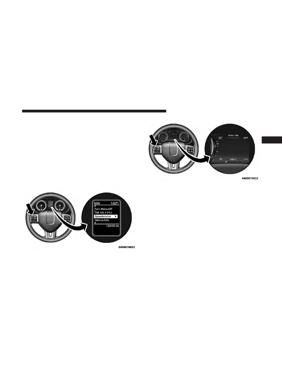
Instrument Cluster Display Selectable Menu Items
Push and release the UP
or DOWN
arrow button
until the desired Selectable Menu icon is highlighted in
the Instrument Cluster Display.
Speedometer
Push and release the UP
or DOWN
arrow button
until the speedometer menu item is highlighted in the
Instrument Cluster Display. Push and release the
RIGHT
arrow button to cycle the display between
MPH and km/h.
Vehicle Info
Push and release the UP
or DOWN
arrow button
until the Vehicle Info menu item is highlighted in the
Instrument Cluster Display. Push and release the
RIGHT
arrow button to enter the submenus items of
Vehicle Info. follow the directional prompts to access or
reset any of the following Vehicle Info submenu items:
• Tire Pressure
• Air Suspension — If Equipped
48
UNDERSTANDING YOUR INSTRUMENT PANEL
• Coolant Temp — If Equipped
• Transmission Temp (Automatic only)
• Oil Temp
• Oil Pressure — If Equipped
• Oil Life
• Battery Voltage — If Equipped
• Gauge Summary — If Equipped
• Engine Hours
Fuel Economy
Push and release the UP
or DOWN
arrow button
until the Fuel Economy menu item is highlighted in the
Instrument Cluster Display. Push and Hold the RIGHT
arrow button to reset Average Fuel Economy.
• Current Fuel Economy Gauge
• Average Fuel Economy value
• Range to Empty
Trip A/Trip B
Push and release the UP
or DOWN
arrow button
until the Trip menu item is highlighted in the Instru-
ment Cluster Display. Push and release the RIGHT
arrow button to enter the submenus of Trip A and
Trip B. The Trip A or Trip B information will display the
following:
• Distance
• Average MPG
• Elapsed Time
Push and hold RIGHT
arrow button to reset all
information.
Air Suspension — If Equipped
Push and release the UP
or DOWN
arrow button
until the Air Suspension menu item is highlighted in the
Instrument Cluster Display. Push and release the
RIGHT
arrow button to display the Air Suspension
status.
3
UNDERSTANDING YOUR INSTRUMENT PANEL
49

Trailer Tow
Push and release the UP
or DOWN
arrow button
until the Trailer Tow menu item is highlighted in the
Instrument Cluster Display. Push and release the
RIGHT
arrow button and the next screen will dis-
play the following trailer trip information:
• Trip (trailer specific) Distance: Push and hold the
RIGHT
arrow button to reset the distance.
• Trailer Brake
• Output
• Type
• Gain
Audio
Push and release the UP
or DOWN
arrow button
until the Audio display icon is highlighted in the
Instrument Cluster Display. Push and release the
RIGHT
arrow button to display the active source.
Screen Setup Menu Item
Push and release the UP
or DOWN
arrow button
until the Screen Setup menu item is highlighted in the
Instrument Cluster Display. Push and release the
RIGHT
arrow button to enter the Screen Setup
submenu. The Screen Setup feature allows you to
change what information is displayed in the instrument
cluster as well as the location that information is
displayed.
Vehicle Settings Menu Item
Personal Settings allows the driver to set and recall features
when the transmission is in PARK.
Push and release the UP
and DOWN
button until
Settings displays in the Instrument Cluster Display.
Follow the prompts to display and set any of the following
Vehicle Settings.
NOTE:
Your vehicle may be equipped with the following
settings.
• If equipped with a base radio (Non-Touchscreen) Vehicle
Settings will be included in the Instrument Cluster
Display.
• If equipped with a Touchscreen radio, the Vehicle Set-
tings will be included in the radio head unit.
50
UNDERSTANDING YOUR INSTRUMENT PANEL
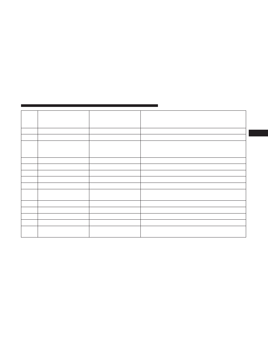
Setting Names
Setting Names Abbre-
viated (Left Submenu
Layer)
Sub-Menus (Right Submenu Layer)
1
Language Select
Language
English, Spanish, French, Italian, German, Dutch
2
Units
Units
U.S.; Metric
3
ParkSense
ParkSense
• Notification — Sound Only; Sound & Display
• Front Volume — Low; Medium; High
• Rear Volume — Low; Medium; High
4
Tilt Mirror in Reverse
Tilt Mirror in R
On; Off
5
Rain Sensing Wipers
Auto Wipers
On; Off
6
Hill Start Assist
Hill Start Assist
On; Off
7
Headlights Off Delay
Lights Off Delay
0 seconds; 30 seconds; 60 seconds; 90 seconds
8
Illuminated Approach
Lights w/ Unlock
0 seconds; 30 seconds; 60 seconds; 90 seconds
9
Headlights On with
Wipers
Lights w/ Wipers
On; Off
10
Automatic Highbeams
Auto Highbeams
On; Off
11
Flash Lights with Lock
Lights w/ Lock
On; Off
12
Auto Lock Doors
Auto Lock Doors
On; Off
13
Auto Unlock Doors
Auto Unlock Doors
On; Off
14
Sound Horn with
Remote Start
Horn w/ Rmt Start
On; Off
3
UNDERSTANDING YOUR INSTRUMENT PANEL
51

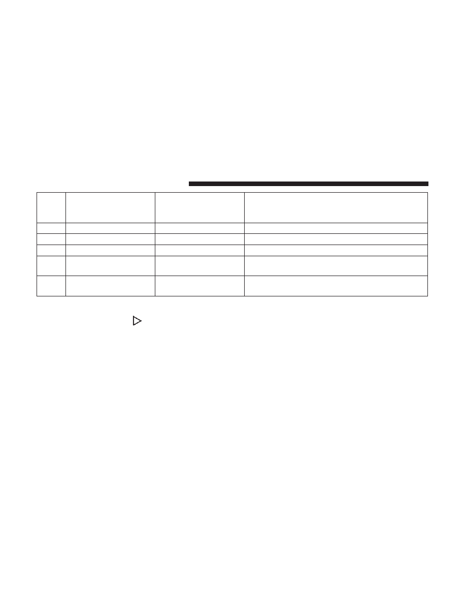
Setting Names
Setting Names Abbre-
viated (Left Submenu
Layer)
Sub-Menus (Right Submenu Layer)
15
Sound Horn with
Remote Lock
Horn w/ Rmt Lock
Off; 1st Press; 2nd Press
16
Remote Unlock
Sequence
Remote Unlock
Driver Door; All Doors
17
Key Fob Linked to
Memory
Key in Memory
On; Off
18
Passive Entry
Passive Entry
On; Off
19
Remote Start Comfort
System
Rmt Start Comfort
Off; Remote Start; All starts
20
Easy Exit Seat
Easy Exit Seat
On; Off
21
Key-off Power Delay
Power Off Delay
Off; 45 seconds; 5 minutes; 10 minutes
22
Commercial Settings
Commercial
• Aux Switches
• Power Take-Off
• PIN Setup
23
Air Suspension Display
Alerts
Air Susp. Alerts
All; Warnings Only
24
Aero Ride Height Mode
Aero Mode
On; Off
25
Tire/Jack Mode
Tire/Jack Mode
On; Off
26
Transport Mode
Transport Mode
On; Off
52
UNDERSTANDING YOUR INSTRUMENT PANEL

Setting Names
Setting Names Abbre-
viated (Left Submenu
Layer)
Sub-Menus (Right Submenu Layer)
27
Wheel Alignment Mode
Wheel Alignment
On; Off
28
Horn w/ Remote Lower
Horn w/ Rmt Lwr
On; Off
29
Lights w/ Remote
Lower
Lights w/ Rmt Lwr
On; Off
30
Trailer Select
Trailer Select
Trailer 1; Trailer 2; Trailer 3; Trailer 4
31
Brake Type
Brake Type
Light Electric; Heavy Electric; Light EOH; Heavy EOH
32
Trailer Name
Trailer Name
• Trailer # (# is equal to slot position)
• Boat
• Car
• Cargo
• Dump
• Equipment
• Flatbed
• Gooseneck
• Horse
• Livestock
• Motorcycle
• Snowmobile
• Travel
• Utility
• 5th Wheel
3
UNDERSTANDING YOUR INSTRUMENT PANEL
53
Setting Names
Setting Names Abbre-
viated (Left Submenu
Layer)
Sub-Menus (Right Submenu Layer)
33
Compass Variance
Compass Var
1-15 increments of 1
34
Calibrate Compass
Compass Cal
Cancel; Calibrate
35
Fuel Saver Display
Fuel Saver
On; Off
36
Park Assist Front Chime
Volume
Park Assist Front Chime
Volume
On; Off
37
Park Assist Rear Chime
Volume
Park Assist Rear Chime
Volume
On; Off
Turn Menu OFF — If Equipped
Push and release the RIGHT
arrow button to exit the
main menu.
Push and release any Instrument Cluster Display control
button to enter the Instrument Cluster Display main menu
again.
Instrument Cluster Display Messages
• Front Seatbelts Unbuckled
• Driver Seatbelt Unbuckled
• Passenger Seatbelt Unbuckled
• Service Airbag System
• Traction Control Off
• Washer Fluid Low
• Oil Pressure Low
• Oil Change Due
• Fuel Low
• Service Antilock Brake System
• Service Electronic Throttle Control
• Service Power Steering
54
UNDERSTANDING YOUR INSTRUMENT PANEL

• Cruise Off
• Cruise Ready
• Cruise Set To XXX MPH
• Tire Pressure Screen With Low Tire(s) “Inflate Tire to
XX”
• Tire Pressure Information System (TPIS)
• Service Tire Pressure System
• Parking Brake Engaged
• Brake Fluid Low
• Service Electronic Braking System
• Engine Temperature Hot
• Battery Voltage Low
• Service Electronic Throttle Control
• Lights On
• Right Turn Signal Light Out
• Left Turn Signal Light Out
• Turn Signal On
• Sound Horn with Remote Lock: Off; 1st Press; 2nd Press
• Vehicle Not in Park
• Key in Ignition
• Key in Ignition Lights On
• Remote Start Active Key to Run
• Remote Start Active Push Start Button
• Remote Start Aborted Fuel Low
• Remote Start Aborted Too Cold
• Remote Start Aborted Door Open
• Remote Start Aborted Hood Open
• Remote Start Aborted Trunk Open
• Remote Start Aborted Time Expired
• Remote Start Disabled Start to Reset
• Service Airbag System
• Service Airbag Warning Light
• Driver Seatbelt Unbuckled
• Passenger Seatbelt Unbuckled
3
UNDERSTANDING YOUR INSTRUMENT PANEL
55

• Front Seatbelts Unbuckled
• Door Open
• Doors Open
• Gear Not Available
• Shift Not Allowed
• Shift to Neutral then Drive or Reverse
• Autostick Unavailable Service Required
• Automatic Unavailable Use Autostick Service Req.
• Transmission Getting Hot Push Brake
• Trans. Hot Stop Safely Shift to Park Wait to Cool
• Transmission Cool Ready to Drive
• Trailer Brake Disconnected
• Service Transmission
• Service Shifter
• Engage Park Brake to Prevent Rolling
• Transmission Too cold Idle with Engine On
• Washer Fluid Low
• Service Air Suspension System
• Heavy Duty Air Suspension System Disabled
• Selected Ride Height Not Permitted Due To Speed
• Selected Ride Height Not Permitted Due To Payload
• Selected Ride Height Not Permitted - Payload Too Light
• Battery Low Start Engine To Change Ride Height
• Normal Ride Height Achieved
• Aerodynamic Ride Height Achieved
• Off Road 1 Ride Height Achieved
• Off Road 2 Ride Height Achieved
• Entry/Exit Ride Height Achieved
• Selected Ride Height Not Permitted
• Service Air Suspension System Immediately
• Reduce Speed To Maintain Selected Ride Height
• Air Suspension System Cooling Down Please Wait
• Vehicle Cannot Be Lowered Door Open
• Off Road 2 Watch For Clearance
56
UNDERSTANDING YOUR INSTRUMENT PANEL
• Entry/Exit Watch For Clearance
• Air Suspension Temporarily Disabled For Jacking And
Tire Change
• Battery Low Start Engine To Change Ride Height
The Reconfigurable Telltales section is divided into the
white telltales area on the right, yellow telltales in the
middle, and red telltales on the left.
Instrument Cluster Display Controls
The Instrument Cluster Display features a driver-
interactive display that is located in the instrument cluster.
The Instrument Cluster Display Menu items may consist of
the following:
• Speedometer
• Vehicle Info
• Fuel Economy Info
• Trip A
• Trip B
• Stop/Start Info (If Equipped)
• Air Suspension (If Equipped)
Base Instrument Cluster Display
Premium Instrument Cluster Display
3
UNDERSTANDING YOUR INSTRUMENT PANEL
57

• Audio
• Trailer Tow
• Stored Messages
• Screen Setup
• Vehicle Settings (Not Equipped with a Uconnect 5.0 &
8.4 radio)
The system allows the driver to select information by
pushing the following Instrument Cluster Display Control
buttons located on the left side of the steering wheel:
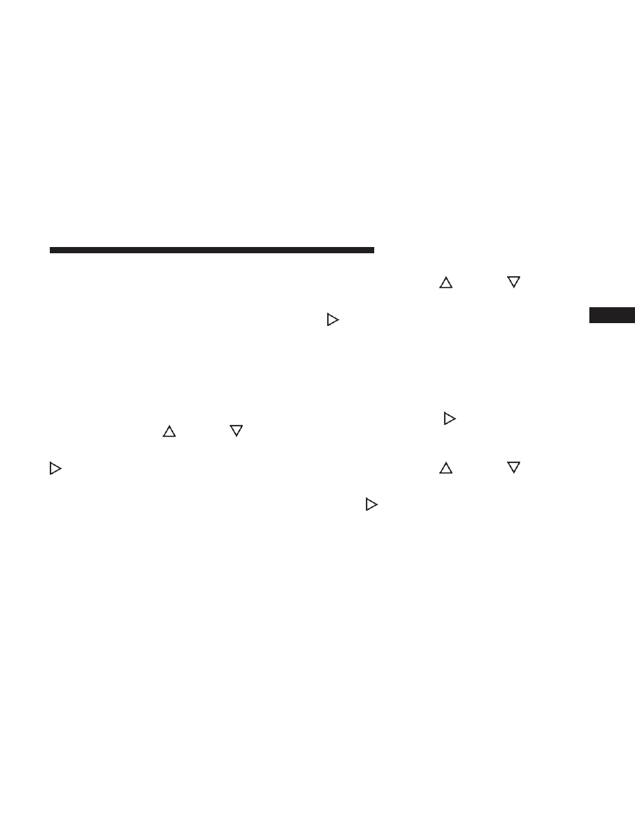
• UP Arrow Button
Push and release the UP arrow button to scroll
upward through the main menu items, submenu
screen, and vehicle settings.
• DOWN Arrow Button
Push and release the DOWN arrow button to
scroll downward through the main menu items,
submenu screen, and vehicle settings.
• RIGHT Arrow Button
Push and release the RIGHT arrow button to
access/select the information screens or sub-
menu screens of a main menu item. Push and
hold the RIGHT arrow button for two seconds to
reset displayed/selected features that can be reset.
• LEFT Arrow Button
Push and release the LEFT arrow button to
access/select the information screens, submenu
screens of a main menu item, or to return to the
main menu.
Instrument Cluster Display Control Buttons
58
UNDERSTANDING YOUR INSTRUMENT PANEL

STARTING AND OPERATING
CONTENTS
䡵 STARTING PROCEDURES . . . . . . . . . . . . . . . . . .60
䡵 FUEL REQUIREMENTS . . . . . . . . . . . . . . . . . . . .60
▫ United States. . . . . . . . . . . . . . . . . . . . . . . . . . .60
▫ Canada. . . . . . . . . . . . . . . . . . . . . . . . . . . . . . .60
䡵 ADDING FUEL . . . . . . . . . . . . . . . . . . . . . . . . . .60
▫ Adding Compressed Natural Gas (CNG) . . . . . . .62
䡵 TRAILER TOWING . . . . . . . . . . . . . . . . . . . . . . .63
4
STARTING PROCEDURES
Your vehicle uses the same starting procedures as de-
scribed in the Ram 1500/2500/3500 Owner’s Manual. No
special starting instructions are required.
NOTE:
Periodically the vehicle will automatically switch
from operation on CNG to Gasoline for a short duration,
depending on conditions. This is done for a number of
reasons, including to maintain the freshness and appropri-
ate seasonal blend of gasoline, to ensure maintenance of
the gasoline injectors and/or to meet high-load demands.
FUEL REQUIREMENTS
United States
Use only natural gas which meets the requirements for gas
quality as specified in National Fire Protection Association
NFPA52 and American National Standard ANSI/ AGA
NGV2. Use of natural gas that does not meet these require-
ments may result in starting and driveability problems and
damage to critical fuel system components.
Canada
Use only natural gas which meets the requirements for gas
quality as specified in Canadian Standards Association
(CSA) B51–M1991 G4.1.2 or SAE J1616. Use of natural gas
that does not meet these requirements may result in
starting and driveability problems and damage to critical
fuel system components.
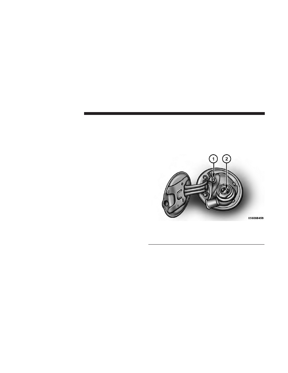
ADDING FUEL
1. Open the fuel filler door.
1 — NGV 1 Receptacle
2 — Gasoline Fuel Filling Receptacle
NOTE:
There is no fuel filler cap. A flapper door inside the
filler pipe seals the system.
Fuel Filler Door
60
STARTING AND OPERATING
2. Insert the fuel nozzle fully into the filler pipe – the
nozzle opens and holds the flapper door while refuel-
ing.
3. Fill the vehicle with fuel – when the fuel nozzle “clicks”
or shuts off the fuel tank is full.
4. Remove the fuel nozzle and close the fuel door.
Emergency Fuel Can Refueling
Most fuel cans will not open the flapper door.
A funnel is provided to open the flapper door to allow
emergency refueling with a fuel can.
1. Retrieve fuel funnel from the jack kit located under the
front passenger seat.
2. Insert funnel into same filler pipe opening as the fuel
nozzle.
NOTE:
Ensure funnel is inserted fully to hold flapper door
open.
3. Pour fuel into funnel opening.
4. Remove funnel from filler pipe, clean off prior to putting
back in the jack kit.
Fuel Fill Funnel Location 2500/3500 Models
4
STARTING AND OPERATING
61
WARNING!
• Never have any smoking materials lit in or near the
vehicle when the fuel door is open or the tank is
being filled.
• Never add fuel when the engine is running. This is
in violation of most state and federal fire regulations
and may cause the “Malfunction Indicator Light” to
turn on.
• A fire may result if fuel is pumped into a portable
container that is inside of a vehicle. You could be
burned. Always place fuel containers on the ground
while filling.
CAUTION!
To avoid fuel spillage and overfilling, do not “top off”
the fuel tank after filling.
Adding Compressed Natural Gas (CNG)
The NGV 1 fuel fill receptacle is mounted in the standard
location behind the fuel filler door. The fill dispenser seals
to the receptacle with an O-ring. Replace the O-ring in the
fill receptacle before refueling if it is damaged or missing;
otherwise natural gas can leak while refueling.
Fueling your natural gas powered vehicle can only be
performed at locations specially equipped to refuel natural
gas vehicles.
NOTE:
There are a number of NGV1 filler nozzles avail-
able. It may be necessary to rotate the nozzle to ensure
clearance to the fuel filler housing or truck bed.
1 — NGV 1 Receptacle
2 — Gasoline Fuel Filling Receptacle
Fuel Filler Door
62
STARTING AND OPERATING

WARNING!
• Do not attempt to force open or tamper with the fuel
fill receptacle. A sudden release of natural gas may
occur, possibly causing injury.
• Your vehicle fuel system has a maximum capacity of
3600 pounds per square inch gauge (24.8 MPa) com-
pensated to a temperature of 70°F (21°C). Exceeding
the fuel system capacity may result in fuel system
damage and possibly cause injury.
• Your vehicle should not be fueled if damage to the
container has occurred. The damaged container
should be retested and inspected as per the Mainte-
nance section prior to be being placed back into
service.
NOTE:
The fuel containers must be visually inspected
every 36 months or 36,000 miles whichever comes first, for
damage and deterioration from the date of manufacture.
The fuel containers expire and must be removed from
service after fifteen years from the date of manufacture. A
label on the CNG tank states the first container inspection
and container expiration date. Refer to “Maintaining Your
Vehicle” in your Owner’s Manual for additional details on
retesting.
TRAILER TOWING
NOTE:
This vehicle is not compatible with gooseneck/
fifth-wheel trailers.
Refer to “Trailer Towing” in “Starting And Operating” in
your Owner’s Manual for further information.
4
STARTING AND OPERATING
63


MAINTAINING YOUR VEHICLE
CONTENTS
䡵 MAINTENANCE PROCEDURES . . . . . . . . . . . . . .66
▫ Container Pressure, Inspection, And Testing . . . . .66
5

MAINTENANCE PROCEDURES
Container Pressure, Inspection, And Testing
Pressure
The vehicle Service Pressure: 24,821 kPa (3,600 psig).
WARNING!
• Do not attempt to force open or tamper with the fuel
fill receptacle. A sudden release of natural gas may
occur, possibly causing injury.
• Your vehicle fuel system has a maximum capacity of
3600 pounds per square inch gauge (24.8 MPa) com-
pensated to a temperature of 70°F (21°C). Exceeding
the fuel system capacity may result in fuel system
damage and possibly cause injury.
• Your vehicle should not be fueled if damage to the
container has occurred. The damaged container
should be retested and inspected as per the Mainte-
nance section prior to be being placed back into
service.
See instructions on fuel container for inspection and service
life.
Inspection
It is recommended that the fuel system components be
inspected periodically for leaks and/or excessive wear.
Container Retest Requirements (United States)
Each CNG fuel container must be visually inspected after a
motor vehicle accident or fire and at least every 36 months
or 36,000 miles, whichever comes first, for damage and
deterioration, in accordance with the Federal Motor Vehicle
Safety Standard number 304 compressed natural gas fuel
containers.
The inspection shall be performed only by a qualified
person in accordance with the container manufacturers
established re-inspection criteria and the appropriate Com-
pressed Gas Association, Inc. guideline. Retest dates must
be marked on a label securely affixed to the container and
over-coated with epoxy near the original test date. Reheat
treatment or repair of rejected containers is not authorized.
The fuel containers expire and must be removed from
service fifteen years from the date of manufacture. A label
on the CNG tank states the first container inspection date
and container expiration date.
66
MAINTAINING YOUR VEHICLE

If there is a question about the proper re-inspection of the
CNG fuel container, contact the manufacturer as identified
on the container label.
Container Retest Requirements (Canada)
Each container must be re-qualified by inspection or testing
after a motor vehicle accident and at least every 36 months
or 57,000 km whichever comes first, or at the time of any
reinstallation in accordance with Canadian Standards As-
sociation B51–97, Part 2.
Retest dates must be marked on a label securely affixed to
the container and over-coated with epoxy near the original
test date. Reheat treatment or repair of rejected containers
is not authorized.
The fuel containers expire and must be removed from
service fifteen years from the date of manufacture. A label
on the fuel container states the first container inspection
date and container expiration date.
If there is a question about the proper re-inspection of the
CNG fuel container, contact the manufacturer as identified
on the container label.
5
MAINTAINING YOUR VEHICLE
67


MAINTENANCE SCHEDULE
CONTENTS
䡵 MAINTENANCE SCHEDULE . . . . . . . . . . . . . . . .70
▫ Required Maintenance Intervals . . . . . . . . . . . . .70
6

MAINTENANCE SCHEDULE
Required Maintenance Intervals
At Each Stop For Fuel
• Inspect the fuel receptacle O-ring for cracks, tears, and
deformation before attaching the fuel station fill line to
the fill port.
Every 15,500 Miles (25,000 km)
• Service the fuel receptacle O-ring.
Every 18,000 Miles (30,000 km)
• Replace the CNG high pressure filter element.
Every 36,000 Miles (57,000 km)
• Inspect each CNG fuel container. Each container must be
re-qualified and inspected every 36 months or 36,000
miles, whichever comes first.
Refer to “Maintenance Schedules” in your Owner’s
Manual for the complete maintenance schedule.
NOTE:
All Required Maintenance Intervals are to be
performed by certified technicians.
70
MAINTENANCE SCHEDULE

INDEX
7

Adding Fuel . . . . . . . . . . . . . . . . . . . . . . . . . . . . . . .60
Air Bag Light . . . . . . . . . . . . . . . . . . . . . . . . . . . . . .17
Alarm (Security Alarm) . . . . . . . . . . . . . . . . . . . . . . .19
Battery . . . . . . . . . . . . . . . . . . . . . . . . . . . . . . . . . . .20
Charging System Light . . . . . . . . . . . . . . . . . . . . .20
Warning Light . . . . . . . . . . . . . . . . . . . . . . . . . . .18
Cruise Light . . . . . . . . . . . . . . . . . . . . . . . . . .39, 40, 41
Electronic Throttle Control Warning Light . . . . . . . . . .21
Turn Signal . . . . . . . . . . . . . . . . . . . . . . . . . . . . . .39
Fog Lights . . . . . . . . . . . . . . . . . . . . . . . . . . . . . . . .32
Fuel
Adding . . . . . . . . . . . . . . . . . . . . . . . . . . . . . . . .60
Light . . . . . . . . . . . . . . . . . . . . . . . . . . . . . . . . . .30
Fueling . . . . . . . . . . . . . . . . . . . . . . . . . . . . . . . . . .60
Instrument Cluster . . . . . . . . . . . . . . . . . . . . . . . .20, 39
Instrument Cluster Display
Instrument Cluster Display . . . . . . . . . . . . . . . . . .42
Air Bag . . . . . . . . . . . . . . . . . . . . . . . . . . . . . . . .17
Brake Warning . . . . . . . . . . . . . . . . . . . . . . . . . . .18
Cruise . . . . . . . . . . . . . . . . . . . . . . . . . . . .39, 40, 41
Engine Temperature Warning . . . . . . . . . . . . . . . . .20
Fog . . . . . . . . . . . . . . . . . . . . . . . . . . . . . . . . . . .32
Low Fuel . . . . . . . . . . . . . . . . . . . . . . . . . . . . . . .30
Malfunction Indicator (Check Engine) . . . . . . . . . . .24
Park . . . . . . . . . . . . . . . . . . . . . . . . . . . . . . . . . .38
Seat Belt Reminder . . . . . . . . . . . . . . . . . . . . . . . .17
Security Alarm . . . . . . . . . . . . . . . . . . . . . . . . . . .19
Tire Pressure Monitoring (TPMS) . . . . . . . . . . . . . .28
Turn Signal . . . . . . . . . . . . . . . . . . . . . . . . . . . . . .39
Warning (Instrument Cluster Description) . . . . .20, 39
Malfunction Indicator Light (Check Engine). . . . . . . . .24
Pressure Warning Light . . . . . . . . . . . . . . . . . . . . .21
Oil Pressure Light . . . . . . . . . . . . . . . . . . . . . . . . . . .21
72
INDEX

Reminder . . . . . . . . . . . . . . . . . . . . . . . . . . . . . . .17
Security Alarm . . . . . . . . . . . . . . . . . . . . . . . . . . . . .19
Settings, Personal . . . . . . . . . . . . . . . . . . . . . . . . . . .50
Signals, Turn. . . . . . . . . . . . . . . . . . . . . . . . . . . . . . .39
Pressure Warning Light . . . . . . . . . . . . . . . . . . . . .28
Turn Signals . . . . . . . . . . . . . . . . . . . . . . . . . . . . . . .39
7
INDEX
73

INSTALLATION OF RADIO TRANSMITTING
EQUIPMENT
Special design considerations are incorporated into this
vehicle’s electronic system to provide immunity to radio
frequency signals. Mobile two-way radios and telephone
equipment must be installed properly by trained person-
nel. The following must be observed during installation.
The positive power connection should be made directly
to the battery and fused as close to the battery as possible.
The negative power connection should be made to body
sheet metal adjacent to the negative battery connection.
This connection should not be fused.
Antennas for two-way radios should be mounted on the
roof or the rear area of the vehicle. Care should be used
in mounting antennas with magnet bases. Magnets may
affect the accuracy or operation of the compass on
vehicles so equipped.
The antenna cable should be as short as practical and
routed away from the vehicle wiring when possible. Use
only fully shielded coaxial cable.
Carefully match the antenna and cable to the radio to
ensure a low Standing Wave Ratio (SWR).
Mobile radio equipment with output power greater than
normal may require special precautions.
All installations should be checked for possible interfer-
ence between the communications equipment and the
vehicle’s electronic systems.

First Edition
Printed in U.S.A.
©2016 FCA US LLC. All Rights Reserved.
Ram is a registered trademark of FCA US LLC.
17D241-CNG-AA
STICK WITH THE SPECIALISTS
®
Document Outline
- INTRODUCTION
- THINGS TO KNOW BEFORE STARTING YOUR VEHICLE
- UNDERSTANDING YOUR INSTRUMENT PANEL
- INSTRUMENT CLUSTER
- WARNING AND INDICATOR LIGHTS
- Red Telltale Indicator Lights
- Seat Belt Reminder Warning Light
- Air Bag Warning Light
- Brake Warning Light
- Vehicle Security Warning Light — If Equipped
- Engine Temperature Warning Light
- Battery Charge Warning Light
- Oil Pressure Warning Light
- Electronic Throttle Control (ETC) Warning Light
- Electric Power Steering Fail Warning Light — If Equipped
- Trailer Brake Disconnected Warning Light
- Door Open Warning Light
- Yellow Telltale Indicator Lights
- Engine Check/Malfunction Indicator Light (MIL)
- Electronic Stability Control (ESC) Indicator Light — If Equipped
- Electronic Stability Control (ESC) OFF Indicator Light — If Equipped
- Low Washer Fluid Indicator Light — If Equipped
- Tire Pressure Monitoring Indicator Light
- Low Fuel Indicator Light
- Anti-Lock Brake (ABS) Indicator Light
- Transmission Temperature Indicator Light
- Rear Fog Light Indicator — If Equipped
- Low Coolant Level Indicator Light
- Air Suspension Payload Protection Telltale — If Equipped
- TOW/HAUL Indicator Light
- Cargo Light — If Equipped
- Loose Fuel Filler Cap Indicator Light — If Equipped
- Air Suspension Off-Road 1 Indicator Light — If Equipped
- Air Suspension Off-Road 2 Indicator Light — If Equipped
- Air Suspension Ride Height Raising Indicator Light— If Equipped
- Air Suspension Ride Height Lowering Indicator Light— If Equipped
- 4WD Indicator Light — If Equipped
- 4WD Lock Indicator Light — If Equipped
- NEUTRAL Indicator Light — If Equipped
- 4 Low Indicator Light — If Equipped
- Service 4WD Indicator Light — If Equipped
- 2WD Indicator Light — If Equipped
- Green Telltale Indicator Lights
- White Telltale Indicator Lights
- Blue Telltale Indicator Lights
- Red Telltale Indicator Lights
- INSTRUMENT CLUSTER DISPLAY
- STARTING AND OPERATING
- MAINTAINING YOUR VEHICLE
- MAINTENANCE SCHEDULE
- INDEX
Wyszukiwarka
Podobne podstrony:
2017 RAM 1500 Special Service
Jak mieć wolną pamięć RAM, A TO POTRZEBNE
transport mat niebezp cng
dobor ram 2012
11 4 3 Lab Install RAM
Jak sprawdzić ilość pamięci RAM (Windows 7 i Windows Vista)
Srodki trwale-wstep, UEP (2014-2017), rachunkowosc
Statyny, Farmakologia sup
Pamięci dynamiczne RAM, Szkoła, Systemy Operacyjnie i sieci komputerowe, utk, semestr I
6 Pamieci ROM RAM id 43808 Nieznany
wst og ram, szkolenia
Ram i szczeg progra okres robot BHP, Szkolenia i popularyzacja zagadnień BHP
06?rambycidae
Ram 02 streszczenie
pract ram
Konstrukcje staloweProjekt wykonawczy ram portalowych
Wykład z rachunkowości 7, UEP (2014-2017), rachunkowosc
Materialy-zadania, UEP (2014-2017), rachunkowosc
więcej podobnych podstron