© PAT Rev. – 05/30/00 // CH.
190073_D.doc
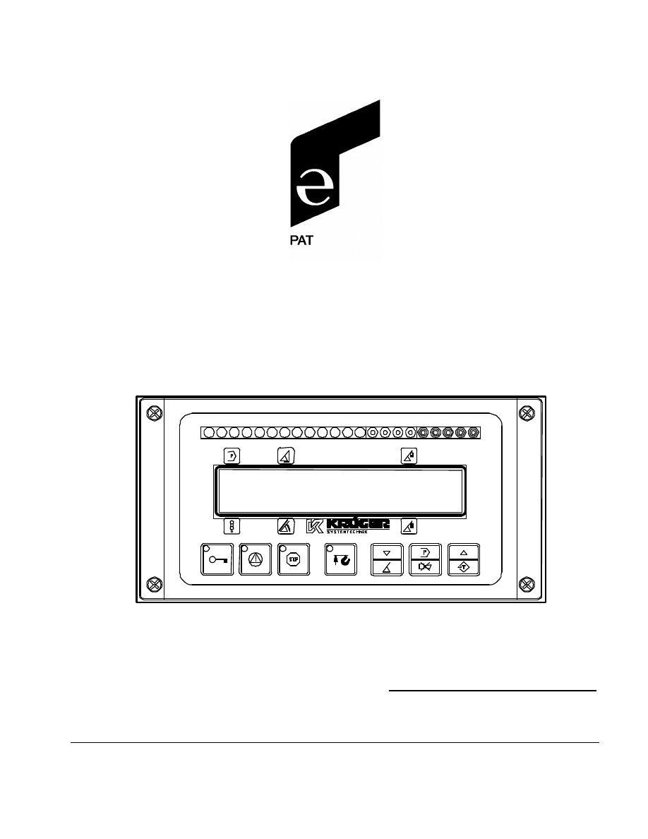
LOAD MOMENT INDICATOR SYSTEM
MARK 4E/2
OPERATOR'S MANUAL
P/N 031-300-190-073, Rev. D 05/30/2000
01
18.1ft
4051lb
02
56.3
°
6850lb

Operator's Manual
/
Mark 4E/2
© PAT Rev. – 05/30/00 // CH.
190073_D.doc
NOTICE
The information in this document is subject to change without notice.
PAT makes no warranty of any kind with regard to this material, including, but not limited to the implied
warranties of merchantability and fitness for a particular purpose.
PAT shall not be liable for errors contained in this manual or for incidental or consequential damages in
connection with the furnishing, performance, or use of this manual. This document contains proprietary
information, which is protected by copyright. All rights are reserved.
No part of this document may be photocopied, reproduced, or translated to another language without the
prior written consent of PAT.
© 1999 PAT America, Chambersburg, PA 17201, USA
Rev. D 2000-05-30 CH.
190073_D.doc

© PAT Rev. – 05/30/00 // CH.
190073_D.doc
TABLE OF CONTENTS
LOAD MOMENT INDICATOR SYSTEM ................................................................................................................ 1
1
GENERAL INFORMATION.............................................................................................................................. 1
2
WARNINGS........................................................................................................................................................... 1
3
SYSTEM DESCRIPTION ................................................................................................................................... 2
4
CRANE CONFIGURATION SETUP................................................................................................................ 6
5
OPERATION.......................................................................................................................................................... 9
6
LMI BYPASSED CONDITION ....................................................................................................................... 10
7
SERVICE MENUS.............................................................................................................................................. 11
8
PRE-OPERATION INSPECTION AND CALIBRATION VERIFICATION......................................... 13
9
ERROR MESSAGES .......................................................................................................................................... 15
10
CONNECTION DESCRIPTION CONSOLE/CENTRAL UNIT............................................................... 16


GENERAL INFORMATION
© PAT Rev. – 05/30/00 // CH.
190073_D.doc
1
1
GENERAL INFORMATION
The KRÜGER load moment system Mark 4E/2 has
been designed to provide the crane
operator with the essential information required to operate the machine within its design
parameters.
Using different sensing devices, the system monitors various crane functions and provides
the operator with a continuous reading of the crane’s capacity. The readings continuously
change, as the crane moves through the motions needed to make the lift.
The Mark 4E/2 provides the operator with information regarding the angle of the boom,
working radius, rated load and the total calculated weight being lifted by the crane.
If non permitted conditions are approached, the Mark 4E/2 will warn the operator by
sounding an audible alarm, lighting a warning light and locking out those functions that may
increase load moment; such as: lowering or extending the boom or lifting the load.
2
WARNINGS
The Mark 4E/2 is an operational aid that warns a crane operator of approaching overload
conditions and of over hoist conditions that could cause damage to equipment and personnel.
The device is not, and shall not, be a substitute for good operator judgment, experience and use
of accepted safe crane operating procedures.
The responsibility for the safe crane operation shall remain with the crane operator who shall
ensure that all warnings and instructions supplied are fully understood and observed.
Prior to operating the crane, the operator must carefully and thoroughly read and understand the
information in this manual to ensure that he knows the operation and limitations of indicator and
crane.
Proper functioning depends upon proper daily inspection and observance of the operating
instructions set forth in this manual. Refer to Section 6. Pre-Operation Inspection and Calibration
Verification of this handbook.
The system can only work correctly, if all adjustments have been properly set. For
correct adjustment, the operator has to answer thoroughly and correctly all questions
asked during the setup procedure in accordance with the real rigging state of the crane.
To prevent material damage and serious or even fatal accidents, the correct adjustment
of the system has to be ensured before starting the crane operation.

Operator's Manual
/
Mark 4E/2
© PAT Rev. – 05/30/00 // CH.
190073_D.doc
2
3 SYSTEM DESCRIPTION
The system operates on the principle of reference/real comparison. The real value, resulting
from the load measurement is compared with the reference and calibration data, stored in
the central processor memory and evaluated in the microprocessor. When limits are reached,
an overload warning signal is generated at the indicator panel/operator’s console. At the
same time, the aggravating crane movements, such as hoist up and boom down, will be
stopped.
The fixed data regarding the crane, such as capacity charts, boom weights, centers of
gravity and dimensions are stored in memory chips in the central processor unit. This data is
the reference information used to calculate the operating conditions.
The Mark 4E/2 consists of:
•
indicator panel (operating console) which displays the following:
§ program number
§ selected parts of line (main/aux)
§ boom radius
§ boom angle/boom length (temporary)
§ load on the hook (actual load)
§ load moment (permitted load)
•
central unit (microprocessor and input/output electronics)
•
angle sensor
•
length sensor
•
pressure sensors
•
Anti-Two-Block switch
(Other combinations are possible depending on demand)
SYSTEM DESCRIPTION
© PAT Rev. – 05/30/00 // CH.
190073_D.doc
3
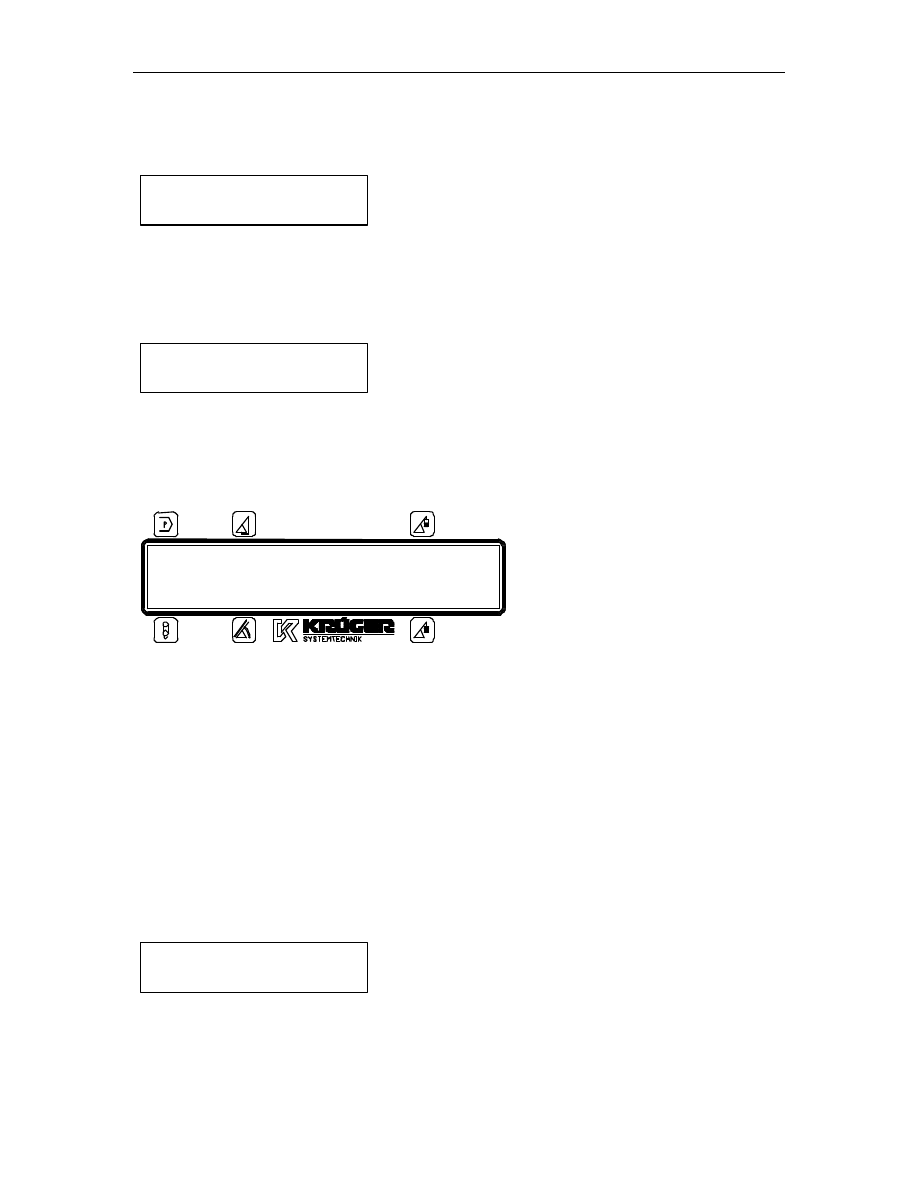
3.1 Operating Console
The console has 3 functions:
•
inputs by the crane operator (operating mode, reeving)
•
input of geometry limit values and signalization of exceeded limit values
•
display of important data and information
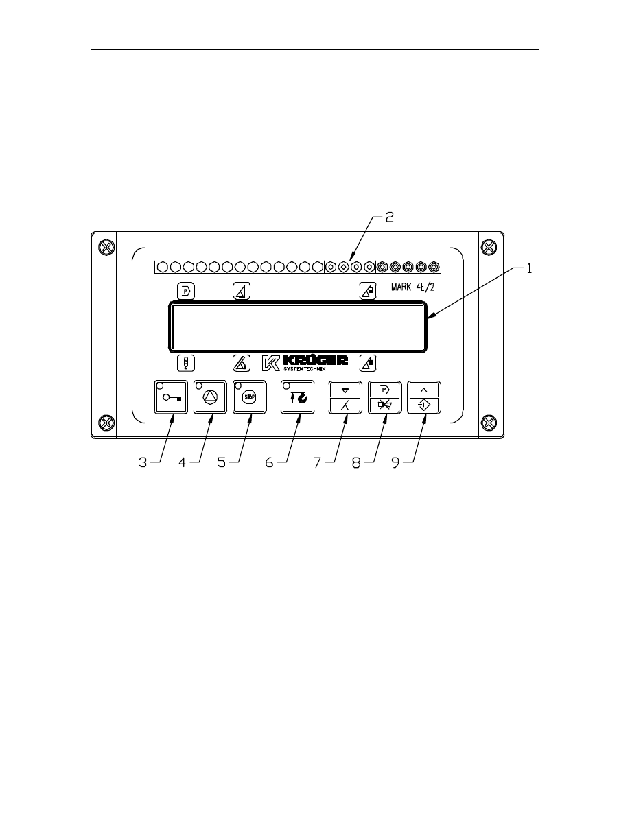
The operator’s console is mounted in the crane’s cab in the operator’s field of vision. For a better
identification of displays and operating elements, they are continuously backlit during operation.
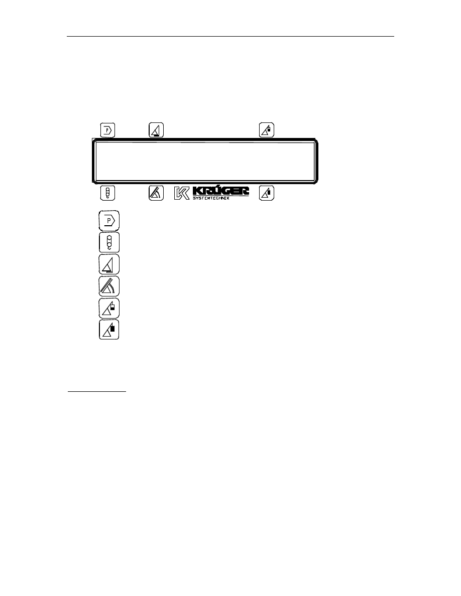
1 Display Area
2 LED bargraph
3 By-Pass Warning Light
4 Load Moment Prewarning Light
5 Load Moment Limit Light
6 Alarm Light “Anti-Two-Block”
7 Down/Boom Length Button
8 Program/“Alarm Stop” Button
9 UP/“TARE” Button
Operator's Manual
/
Mark 4E/2
© PAT Rev. – 05/30/00 // CH.
190073_D.doc
4
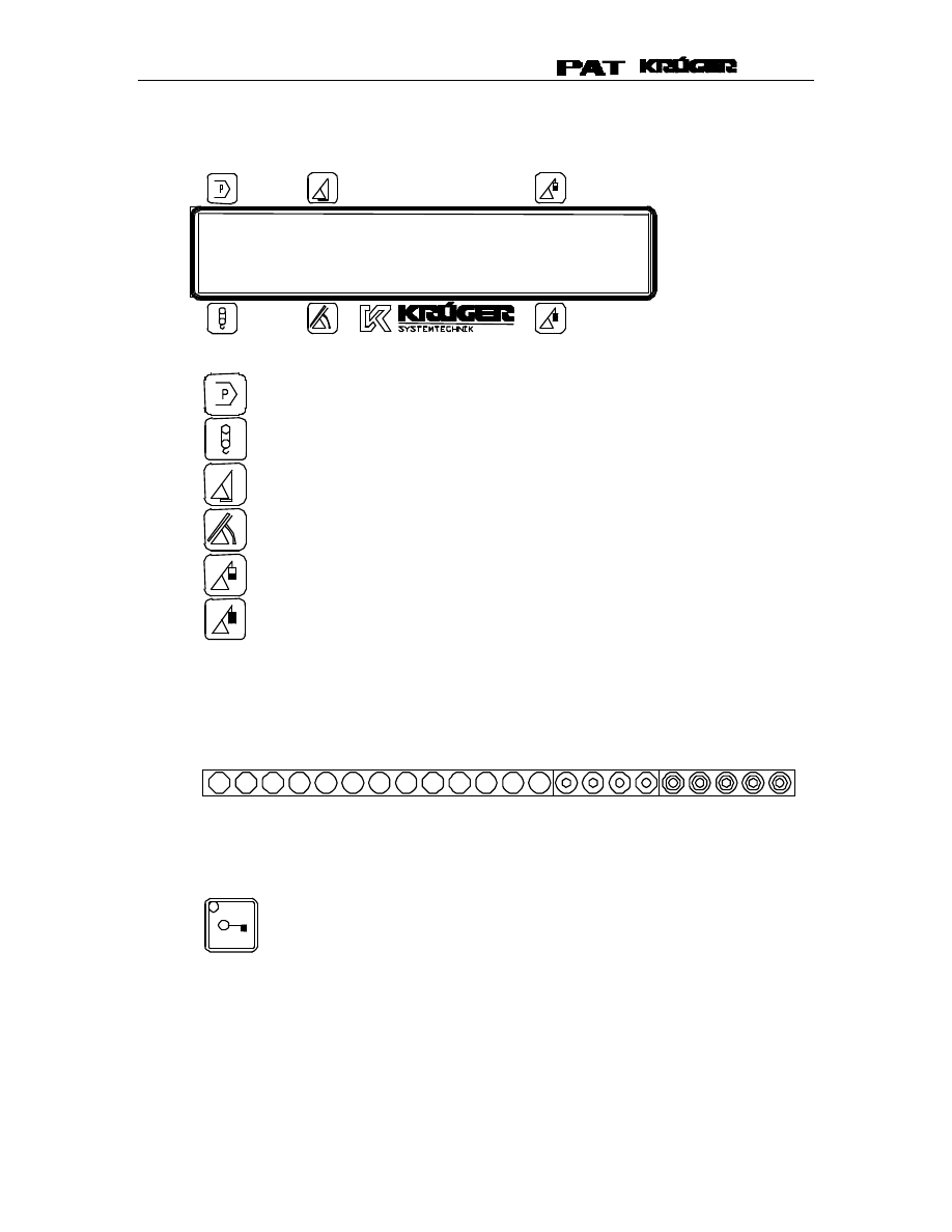
3.1.1 Display Area
program number
(example above shows 01)
selected parts of line (main/aux)
(example above shows 02)
boom radius
(example above shows 18.1ft)
boom angle or temporary boom length
(example above shows 56.3
°
)
load on the hook (actual load)
(example above shows 4051lb)
load moment (permitted load)
(example above shows 6850lb)
All information, except the boom length, which only can be set on demand by a
pushbutton, is monitored at a time by a backlighted LC display (1).
3.1.2 LED Bargraph
The load moment information will clearly be monitored by an LED bargraph (2),
consisting of 22 LEDs (13 green, 4 yellow and 5 red ones).
3.1.3 By-Pass Warning Light
The red BY-PASS WARNING LIGHT (3) turns on to indicate that the cutoff
function of the LMI system is deactivated.
01
18.1ft
4051lb
02
56.3
°
6850lb

SYSTEM DESCRIPTION
© PAT Rev. – 05/30/00 // CH.
190073_D.doc
5
3.1.4 Load Moment Prewarning Light
The yellow LOAD MOMENT PRE-WARNING LIGHT (4) will light up when the
load on the crane reaches the defined prewarning area, thus indicating that an
overload condition is approaching.
This means for the operator to continue crane operation with extreme
caution.
3.1.5 Load Moment Limit Light
The red LOAD MOMENT LIMIT LIGHT (5) warns the operator that a maximum
load condition has been reached. It lights up when the load on the crane
reaches the crane load capacity. The audible alarm also sounds when this
condition has been reached.
The following crane movements will be stopped concurrently:
⇒
hoist up
⇒
telescope out
⇒
boom down
3.1.6 Alarm Light “Anti-Two-Block”
The red “Anti Two-Block Alarm Light” (6) lights up when the anti-two-block limit
switch contacts open, indicating that a two-blocking condition is approaching.
At the same time the audible alarm will sound.
The following crane movements will be stopped subsequently: hoist up and
boom down (depending on your machine).
3.1.7 Down/Angle-Length Button
During operation, the operator can toggle between the displaying boom angle
or boom length, by pressing the “DOWN/ANGLE-LENGTH (7).
The down button is used during programming/calibration procedures to scroll
through menu options.
3.1.8 Program/“Alarm Stop” Button
The PROGRAM BUTTON (8) starts the programming function to "crane
configuration setup".
Pressing the ALARM STOP BUTTON (8) allows the audible alarm to be
temporally silenced.
3.1.9 UP/“TARE” Button
During operation, this button allows the actual load to be tared, set to zero. It
can be cancelled by pressing the pushbutton, UP/TARE (9) again. The load
dimension “lb” (or “t”, “Kg”) flashes during the tare condition. Note: The tared
condition will also be cancelled when:
⇒
the system has been switched off
⇒
the program number or parts of line as been changed
⇒
the boom has been telescoped in/out more than 1m
⇒
the boom has been changed more than ±3
°
The up button is use during programming/calibration procedures to scroll
through menu options.
Operator's Manual
/
Mark 4E/2
© PAT Rev. – 05/30/00 // CH.
190073_D.doc
6
4
CRANE CONFIGURATION SETUP
The Mark 4E/2 setup procedure allows the operator to input the crane configuration using the
following displays. The operator must complete the setup procedure for the Mark 4E/2 system
before operating the crane.
On initial power up, the configuration setup procedure consists of the following steps:
•
setting the program number (boom type and counterweight configuration)
•
specify the hoist configuration (optional)
•
specify the parts of line (reeving)
After pressing the
PROGRAM/BUZZER (8) key, the configuration setup procedure consists of
the following steps:
•
setting the program number (boom type and counterweight configuration)
•
specify the hoist configuration (optional)
•
specify the parts of line (reeving)
•
specify the angle presets (minimum/maximum)
•
confirmation of the crane configuration and Mark 4e/2 setup
The correct crane configuration setting is of utmost importance for the proper functioning
of the system and the crane. Therefore, only operators who are thoroughly familiar with
the crane and the operation of the system should execute the setting of the system
according to the operating configuration of the crane.
After switching on the supply voltage the unit will complete a system check routine for 1 second,
where all LEDs and the buzzer are activated. After successful check the display will show:
The displayed number is the valid program/software number of the system. Then the display
automatically switches over to the crane configuration setup. This allows the operator to select
the existing crane configuration.
Use the pushbuttons, DOWN/ANGLE-LENGTH” (7) or UP/TARE” (9) to toggle down or up to the
operating load chart program number that matches the actual crane configuration. Confirm the
displayed selection with the pushbutton PROGRAM/BUZZER (8).
“KRÜGER SYSTEMTECHNIK”
#116xxx”
01:ON OUTR EXT 6m
31m JIB 7.5m/ 5
°
CRANE CONFIGURATION SETUP
© PAT Rev. – 05/30/00 // CH.
190073_D.doc
7
If available, the display will request the operator specify the hoist/winch selection. If not available
the display switches directly to the parts of line selection mode.
Use the push buttons DOWN/ANGLE-LENGTH (7) or UP/TARE (9), to specify the hoist/winch.
Confirm displayed selection with the pushbutton PROGRAM/BUZZER (8).
The display will request the parts of line configured.
Use the push buttons DOWN/ANGLE-LENGTH (7) or UP/TARE (9) to select the number of parts
of line. Confirm displayed selection with the pushbutton PROGRAM/BUZZER (8).
The normal operating display OR the minimum angle preset selection mode will be displayed at
this time.
If the displayed values are incorrect or the setup is changed since the crane was powered off,
press the pushbutton PROGRAM/BUZZER (8) to restart the configuration setup procedure
(CRANE CONFIGURATION SETUP).
NOTE: To preset angle limits select the PROGRAM/BUZZER (8) key to restart the configuration
setup procedure (CRANE CONFIGURATION SETUP).
If display is correct, go to Section 5.
If the operator restarted the configuration setup procedure by pressing the pushbutton
PROGRAM/BUZZER (8) the angle preset selection mode will be displayed and the operator must
complete the following steps.
The display switches over to the minimum angle preset selection mode.
The indicated angle is the value already stored in memory.
SELECT WINCH
MAIN
PARTS OF LINE
02
01
18.1ft
4051lb
02
56.3
°
6850lb
ANGLE PRESET MIN.
26.0
°

Operator's Manual
/
Mark 4E/2
© PAT Rev. – 05/30/00 // CH.
190073_D.doc
8
When setting the preset angle limit, always keep a safe working distance to any
obstacles. Never work outside a safe working area as outlined by common practice,
standards, and manuals.
To change the stored value, move the boom to the minimum/maximum angle. Store the position
into the memory by pressing the pushbutton UP/TARE (9). The new value will be shown on the
display at this time.
To disable the preset limits, press the pushbutton DOWN/ANGLE-LENGTH (7).
Confirm displayed selection with the pushbutton PROGRAM/BUZZER (8).
Complete the maximum angle preset same as the minimum.
Confirm displayed selection with the pushbutton PROGRAM/BUZZER (8).
ANGLE PRESET MAX.
68.0
°
OPERATION
© PAT Rev. – 05/30/00 // CH.
190073_D.doc
9
5
OPERATION
After having set the Mark 4E/2 to the actual crane configuration, the system is ready for
operation. The display shows:
Program number
(example above shows 01)
Selected parts of line (main/aux)
(example above shows 02)
boom radius
(example above shows 18.1ft)
boom angle or temporary boom length
(example above shows 56.3
°
)
load on the hook (actual load)
(example above shows 4051lb)
load moment (permitted load)
(example above shows 6850lb)
Press the pushbutton PROGRAM/BUZZER (8) to restart the configuration setup procedure and
complete Section 4 CRANE CONFIGURATION SETUP.
Angle Limit Setup
To set angle limits press the pushbutton PROGRAM/BUZZER (8) to restart the programming
procedure and follow the instruction in Section 4 CRANE CONFIGURATION SETUP.
01
18.1ft
4051lb
02
56.3
6850lb
Operator's Manual
/
Mark 4E/2
© PAT Rev. – 05/30/00 // CH.
190073_D.doc
10
6
LMI BYPASSED CONDITION
The LMI can be placed in a bypass condition for rigging operation. The switch is located on the
central unit and the bypassed condition will show on the console by the “LMI BYPASSED” pilot
lamp (3).
Since BYPASSING deactivates the lockout function of the load moment and the anti two-
block system, the following instructions must be obeyed:
•
The by-pass function shall be used with discretion, as unwarranted use of it to
override the control lever lockout system can result in harm to the crane and danger
to property and persons.
•
Never use the by-pass function to either overload or operate the crane in a non-
permissible range.
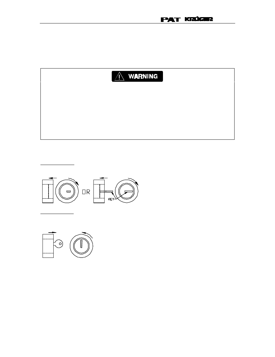
Key switch positions:
Normal operation: the inter portion of the key switch is pushed in and turned clockwise for normal
operation.
Bypass condition: From the normal position, insert and turn the key counter-clockwise so the inter
portion of the key switch is flush and key is locked in place. The key can not be removed while in
a bypass condition.
SERVICE MENUS
© PAT Rev. – 05/30/00 // CH.
190073_D.doc
11
7
SERVICE MENUS
The Mark 4E/2 consists of two service menus:
•
An accessible menu for the operator that allows user to adjust the LED brightness and select
a language (optional, if there is only one preprogrammed language this selection will not be
available.)
•
A service menu that is protected by an access code and allows sensor and calibration
adjustment. For further description refer to the calibration manual 031-300-190-074.
The LMI function is not active while in the service menu. In this mode, the crane operator
is responsible for safe operation of the crane.
The accessible menu can be initialized by simultaneously pressing the PROGRAM/BUZZER (8)
and DOWN/ANGLE-LENGTH (7) keys.
When a menu is displayed, the flashing menu point can be selected by using the
PROGRAM/BUZZER (8) key or select the UP/TARE (9) or DOWN/ANGLE-LENGTH (7) to select
another menu point.
7.1 Led-Brightness
The brightness of the LED bargraph (2) can be adjusted. When this menu point has been
selected, all LEDs will be turned on and following information will be displayed.
Adjust the brightness with the “UP“ and “DOWN“ keys. Brightness can be adjusted in 16 steps
from 1-16.
Press the “PROGRAM“ key to confirm the selected value and the system will return to the last
menu.
LED-BRIGHTNESS
04

Operator's Manual
/
Mark 4E/2
© PAT Rev. – 05/30/00 // CH.
190073_D.doc
12
7.2 Language
After selecting the language menu point, the following will be displayed.
The language currently selected will be displayed, use the “UP“ and “DOWN“ keys to select the
preprogrammed languages.
Press the “PROGRAM“ key to confirm the selected value and the system will return to the last
menu. In case the language has been changed, the system will generate a reset.
7.3 Reset
This menu point will generate a system reset similar to when the system is switched on.
7.4 Exit
When this menu point has been selected, the system will return to the load chart setup.
SELECT LANGUAGE
ENGLISH
PRE-OPERATION INSPECTION AND CALIBRATION VERIFICATION
© PAT Rev. – 05/30/00 // CH.
190073_D.doc
13
8
PRE-OPERATION INSPECTION AND CALIBRATION
VERIFICATION
The following tests shall be performed with care to prevent damage to the machine or
injury to personnel. Proper functioning of the system requires successful completion of
these tests before operating the machine.
Before operating the crane, the following electrical connections must be checked to ensure
that the system is properly connected for the crane configuration.
After the electrical connections have been checked to insure that the system is properly
connected for the crane configuration, the following checks shall be made:
1) Check the electrical wiring connecting the various parts of the system for physical damage.
2) Check the spring-loaded cable reel to be sure it is free to rotate, has tension and the cable is
reeled properly.
Failure to re-position the anti two-block switch weight will prevent the over hoist system
from functioning properly. No weight shall be on the main hoist anti two-block switch
when the boom extension is being used.
3) Check the anti two-block switches and weights for free movement.
If the operator cannot see the load-handling device approaching the boom nose, he shall have an
assistant (signal person) watch the load-handling device. The operator shall be prepared to stop
the machine immediately should the LMI system not function properly as indicated by lighting the
red warning light (6), sounding the audible alarm and locking the crane movements, hoist up,
telescope out and boom down.
4) Check the anti two-block alarm light (6) and the audible alarm by performing one of the
following tests:
a) By manually lifting the weight attached to the anti two-block switches. When the weight is
lifted, the audible alarm should sound; the anti two-block alarm light (6) should light.
b) Slowly raise the main boom load-handling device to create a potential two-block
condition. When the load-handling device lifts the weight, the audible alarm should
sound, the anti two- block alarm light (6) should light and the motion of the load-handling
device should be stopped. Lower the load-handling device slightly to eliminate this
condition.
c) Slowly lower the boom to create a potential two-block condition. When the load-handling
device lifts the weight, the anti two-block audible alarm and light should turn on and the
boom telescoping function should be stopped. Lower the load-handling device slightly to
eliminate this condition.
d) Slowly extend (telescope) the boom to create a potential two-block condition. When the
load-handling device lifts the weight, the anti two-block audible alarm and light should
turn on and the boom lowering function should be stopped. Lower the load-handling
device slightly to eliminate this condition.

Operator's Manual
/
Mark 4E/2
© PAT Rev. – 05/30/00 // CH.
190073_D.doc
14
If the light and audible alarm do not function as described and the crane movements are
not stopped, the system is not working properly. The malfunction shall be corrected
before operating the crane.
5) If the crane is equipped with a boom extension, repeat the test procedure for the boom
extension anti two-block switch. Check that the display of the main boom length agrees with
the actual boom length.
6) Check that the display of the main boom angle agrees with the actual boom angles.
7) Check that the display of the operating radius of the crane agrees with the actual radius.
8) Check the load display by lifting a load of known weight.

LOAD MOMENT INDICATOR SYSTEM
© PAT Rev. – 05/30/00 // CH.
190073_D.doc
15
9
ERROR MESSAGES
There are (2) different kinds of errors: system or operation. When an error occurs this means the
system has a fault. The description and number of errors will appear on the screen.
System errors will occur if a system component has failed or been damaged and must be
corrected and then the system needs to be reset to continue operation.
Operation errors are measurement errors, i.e.; the actual radius is lower than in the load chart.
The information will be shown on the second line of the display with an error message or
description. The error will be automatically reset when user corrects error.
Errors are numbered by the significance of the error; the highest priority is listed first. Example: If
there are three messages in line two, the display will show 1/3 (1 of 3). The first number indicates
the error, which is displayed. The second number indicates the number of errors.
If a second or third error exists press the pushbutton UP/TARE” (9) to see the description of the
error.
During an Error Condition:
To switch back to the operating screen pushbutton “DOWN/ANGLE-LENGTH” (7) has to be
pressed. If however the operator wants to switch over again to the error message, he has to
press the pushbutton “DOWN/ANGLE-LENGTH” (7) twice.

Operator's Manual
/
Mark 4E/2
© PAT Rev. – 05/30/00 // CH.
190073_D.doc
16
10 CONNECTION DESCRIPTION CONSOLE/CENTRAL UNIT
The tables below show the connection terminal wire color and terminal description for the 7m long
supplied cable between the console and central unit.
Connections to the central unit
Terminal
Function
Lead Color
X1:1
Supply voltage +12VDC (opt. 24VDC)
X1:2
Input GND (OV)
X1:3
Output Uref 3,8VDC, for slewing angle sensor
X1:4
Output Uref 3,8VDC, for slewing angle sensor
X1:5
Output Uref 1,0VDC, for slewing angle sensor
X1:6
Output Uref 1,0VDC, for slewing angle sensor
X1:7
Interface RS232 TxD
X1:8
Interface RS232 RxD
X1:9
Interface RSRS232 CTS
X1:10
Interface RS232 DTR
X1:11-20
+12VDC
X1:21-26
+ 5VDC/Vref
X1:27
Interface RS422 CLK+
Green (from indicator panel)
X1:28
Interface RS422 CLK-
Yellow (from indicator panel)
X1:29
Interface RS422 Data+
Grey (from indicator panel)
X1:30
Interface RS422 Data-
Pink (from indicator panel)
X1:31
Supply voltage indicator panel 24/12VDC
X1:32
Supply voltage indicator panel, 0VDC (GND)
Brown (from indicator panel)
X1:33
Indicator panel +12VDC
White (from indicator panel)
X1:34
Indicator panel shut off
Jumper to X1.41
X1:35
Indicator panel RxD+
X1:36
Indicator panel RxD-
X1:37
Indicator panel TxD+
X1:38
Indicator panel TxD-
X1:39
Indicator panel heating GND
X1:40
Indicator panel heating 24/12VDC
X1:41-50
GND
X1:51
Analog input 1 (Pressure transducer piston side)
X1:52
Analog input 2 (Pressure transducer rod side)
X1:53
Analog input 3 (length transducer)
X1:54
Analog input 4
X1:55
Analog input 5
X1:56
Analog input 6 (angle transducer)
X1:57
Analog input 7
X1:58
Analog input 8
X1:59
Interface RS422 Load +
Blue (from indicator panel)
X1:60
Interface RS422 Load -
Red (from indicator panel)
X1:61
Roller switch 1 Front rubber
X1:62
Roller switch 2 Front/Rear outrigger
X1:63
Roller switch 3
X1:64
Roller switch 4
X1:65
Roller switch 5
X1:66
Down button
Grey/pink (from indicator
panel)
X1:67
Prog button
Violet (from indicator panel)

LOAD MOMENT INDICATOR SYSTEM
© PAT Rev. – 05/30/00 // CH.
190073_D.doc
17
X1:68
Up button
Black (from indicator panel)
X1:69
Roller switch GND 1…8
X1:70
n.c.
X1:71
Hoist limit switch
X1:72
Hoist limit switch +12VDC
X1:73
Bypass hoist limit switch
Red/blue (from indicator
panel)
X1:74
Bypass hoist limit switch
X1:75
Bypass LMI
X1:76
Bypass LMI
X1:77-78
Shutoff 1
X1:79-80
Shutoff 2
Console Table 1. Console connection
Terminal
Description
Lead Color
X1:1
+24VDC
White
X1:2
OVDC, GND
Brown
X1:3
RS422 CLK+
Green
X1:4
RS422 CLK-
Yellow
X1:5
RS422 DATA+
Grey
X1:6
RS422 DATA-
Pink
X1:7
RS422 Load+
Blue
X1:8
RS422 Load-
Red
X1:9
Push button UP/TARE”
Black
X1:10
Push button PROGRAM/BUZZER
Violet
X1:11
Push button DOWN/ANGLE-
LENGTH”
Grey/pink
X1:12
Push button HOIST LIMIT SWITCH”
Red/blue

Operator's Manual
/
Mark 4E/2
© PAT Rev. – 05/30/00 // CH.
190073_D.doc
18
MANUAL REVISIONS
REV
DATE
NAME
DESCRIPTION
D
05/30/00
CSH
Changed lead color from indicator panel from grey/pink to blue
Wyszukiwarka
Podobne podstrony:
Mark 4E2 Operators manual Spanish
Mark 4E2 Calibration
Krueger Mark H Operators
The uA741 Operational Amplifier[1]
operatory i funkcje matematyczne
operator maszyn lesnych 833[02] o1 03 n
mechanik operator pojazdow i maszyn rolniczych 723[03] z2 04 n
Kierowca operator wózków jezdniowych 833401
mechanik operator pojazdow i maszyn rolniczych 723[03] o1 05 u
OPERAT STABLE VERSION ugoda id Nieznany
operator urzadzen przemyslu szklarskiego 813[02] z2 07 n
4 Steyr Operation and Maintenance Manual 8th edition Feb 08
operator urzadzen przemyslu spozywczego 827[01] z2 02 u
mechanik operator pojazdow i maszyn rolniczych 723[03] z3 02 n
więcej podobnych podstron